

Page 1
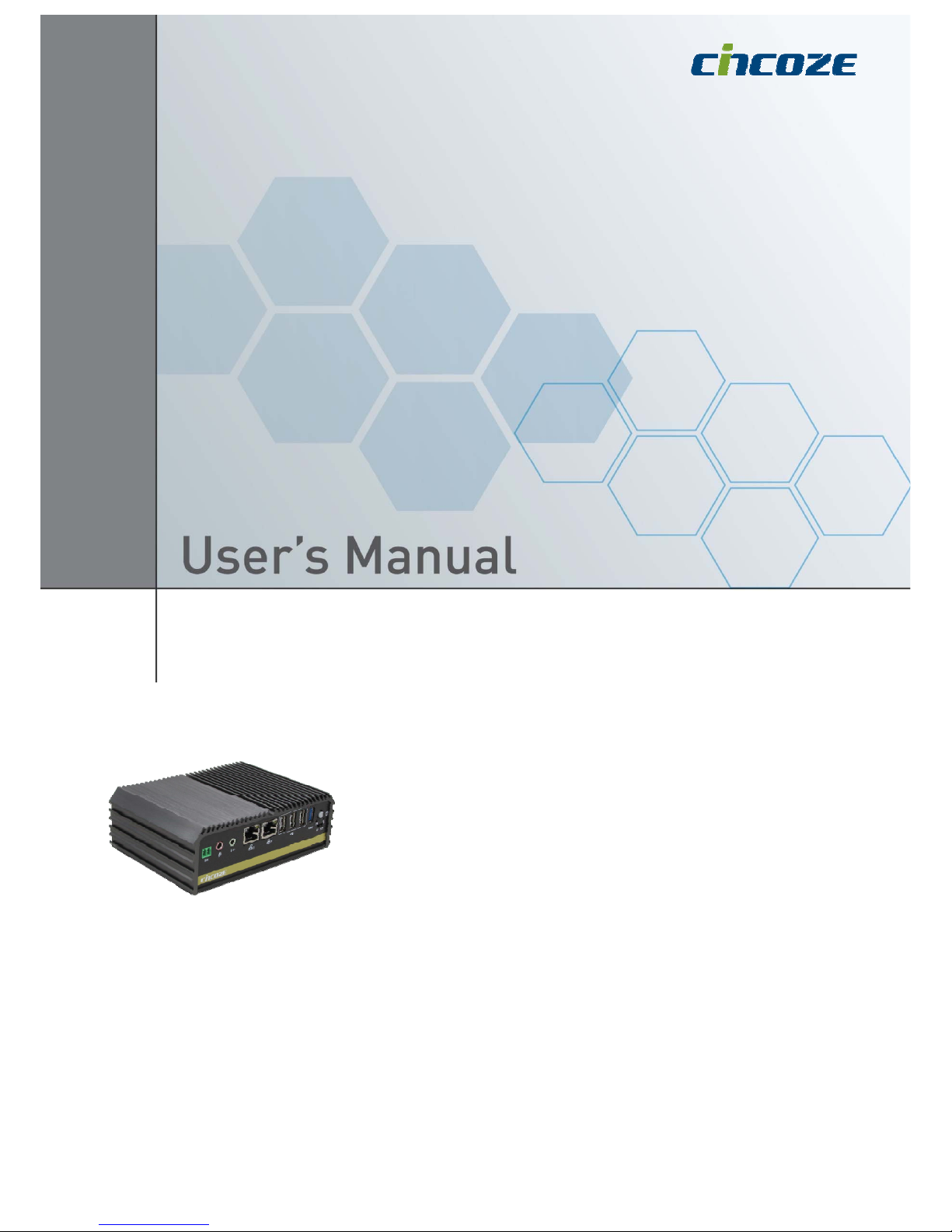
Intel® Atom™ or Celeron® Processor
Affordable Fanless Embedded Computer
DA-1000
Fanless Computing Solution
DOC No: DA-20170515002_R1.31
Page 2

DA-1000 User’s Manual
2
Contents
Prefaces
Revision …………………………………………………..……………….……….. 05
Copyright Notice …………………………………………………………………… 05
Acknowledgement …..……………………………………………….................... 05
Disclaimer ………………………………………………………………………….. 05
Declaration of Conformity ………………………………………………………… 05
Product Warranty Statement …………………………………………………….. 06
Technical Support and Assistance ………………………………………………. 07
Conventions Used in this Manual ……………………………………………….. 07
Safety Precaution ……...………………………………………………………….. 08
Package Content …..……………………………………………………………… 09
Ordering Information …………………….………………………………………… 10
Optional Modules & Accessories ……..……………………………..................... 11
Chapter 1 Product Introductions
1.1 Overview ……………………………………………….……………….. 13
1.1.1 Key Features ……..………….……….……………………....... 13
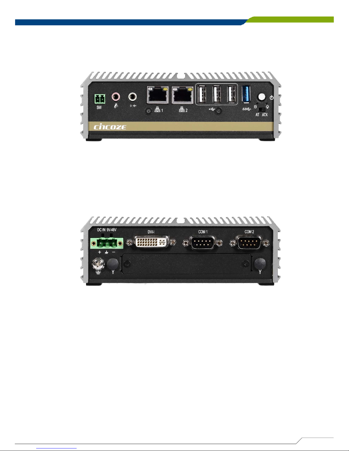
1.1.2 Photo of Front Panel …..…………………………………….......14
1.1.3 Photo of Rear Panel …..……………………………………....... 14
1.2 Hardware Specification …..…………………………………………… 15
1.3 System I/O ……………………………………………………………… 16
1.4 Mechanical Dimension …..……………………………………………. 18
Chapter 2 Jumpers and Connectors
2.1 Jumper Setting ………………………………………………………..... 20
2.2 Location of the Switches and Connectors……..…………………….... 20
2.2.1 Top View ………………………………………………………… 20
2.2.2 Bottom View …………………………………………………….. 21
2.3 List of Switches and Connectors ……..,……………….………........... 22
2.4 Switches Definitions …..……………………....................................... 23
2.5 Connectors Definitions ..………………………................................... 24
2.5.1 Mini PCI-Express / mSATA Socket….…………………….……24
2.5.2 MINIPCIE1:Mini PCI-Express Socket………..………...…… 25
2.5.3 SIM1:SIM Card Socket…………………………………..…… 26
2.5.4 DC_IN1:DC Power Input Connector (9~48V)………….…… 26
2.5.5 PWR_SW2:External remote power on/off switch……...……26
2.5.6 COM1_1:RS232 / RS422 / RS485 Connector…..…….…… 27
2.5.7 COM2_1:RS232 / RS422 / RS485 Connector.………...……27
2.5.8 COM3、COM4:Voltage Select……….………………...…… 28
2.5.9 DVI_I1:DVI-I Connector……..…………………………..…… 28
2.5.10 LAN1:RJ45 with LED Connector………..…….……….…… 29
2.5.11 LAN2:RJ45 with LED Connector………………………..……29
Page 3

DA-1000 User’s Manual
3
2.5.12 LED1:Power / HDD Access LED Status……………...…… 29
2.5.13 LINE_OUT1: Line-out Jack (Green)………………..…… 30
2.5.14 MIC1: Microphone Jack (Pink)………………………..….…… 30
2.5.15 SATA1:SATA Connector……………………………..….…… 30
2.5.16 USB1、USB2 、 USB3:USB2.0 Connector, Type A...…… 31
2.5.17 USB4:USB3.0 Connector, Type A……………………..…… 31
Chapter 3 System Setup
3.1 Removing the Chassis Bottom Cover ……...………………………... 33
3.2 Removing the Chassis …………………….…..…….……………….... 34
3.3 Installing the Antennas…………………………………………………. 35
3.4 Installing a Full-Size Mini PCIe Card on Bottom Side…....……….... 37
3.5 Installing a SATA Hard Drive……………………………………………. 39
3.6 Installing a SODIMM……….……………………..….……………....... 40
3.7 Installing the Chassis ………….…………..………..….…………….... 41
3.8 Installing the Chassis Bottom Cover …..…………..….…………….... 42
3.9 Installing a SIM Card ………………………………..…………………. 43
3.10 Wall Mount Brackets ..……….………………….…..….…………….... 44
3.11 Side Mount Bracket……………………………………………………….45
3.12 VESA Mount Bracket…………………………………………………… 47
3.13 DIN-Rail Mount Bracket…………………………………………………. 48
Chapter 4 BIOS Setup
4.1 BIOS Introduction ……..……….………………….…..….…………... 50
4.1.1 BIOS Setup…..………………………………………………….. 50
4.1.2 Main Menu……………………………………………………….. 50
4.1.3 Sub-Menu…………………………………………………….….. 50
4.2 Main Setup ……..……….………………….…..………………………... 51
4.2.1 System Date ….………………………………………………….. 51
4.2.2 System Time ….………………………………………………….. 51
4.3 Advanced Setup ...……….………………….…..….…..……………... 52
4.3.1 ACPI Settings …..…….………………………………………….. 52
4.3.2 Super I/O Configuration ..………………………………………. 53
4.3.3 Hardware Monitor…….……………………………………………57
4.3.4 Serial Port Console Redirection………………………………… 58
4.3.5 CPU Configuration……..………………………………………… 59
4.3.6 Thermal Configuration…………..……………………………….. 61
4.3.7 SATA Configuration.……………………………………………… 62
4.3.8 OS Selection……………………..……………………………….. 64
4.3.9 CSM Configuration…..…………………………………………… 65
4.3.10 USB Configuration …………………………………….……….. 67
4.4 Chipset …………………………………………………………………….69
4.4.1 North Bridge……………………………………………………… 69
4.4.2 South Bridge……………………………………………………… 71
4.5 Security…………………………………………………………………….74
4.5.1 Administrator Password………………………………………….. 74
4.5.2 User Password………….……..…………………………………. 74
Page 4

DA-1000 User’s Manual
4
4.6 Boot…..…………………………………………………………………….75
4.6.1 Setup Prompt Timeout..………………………………………….. 75
4.6.2 Bootup NumLock State.……..…………………………………. 75
4.6.3 Full Screen Logo Show………………………………………….. 75
4.6.4 Fast Boot…………………….. ……………………………………75
4.6.5 UEFI Boot…………… …………………………………………… 75
4.7 Save & Exit …...……….….………………….…..….…..….…………... 76
4.7.1 Save Changes and Reset………………………………………. 76
4.7.2 Discard Changes and Reset……………………………………. 76
4.7.3 Restore Defaults …………………………………………………. 76
4.7.4 Save as User Defaults ……………………………………………76
4.7.5 Restore User Defaults ………………………..…………………. 76
Chapter 5 Product Application (For CMI-DIO100 Only )
5.1 Digital I/O (DIO) application……………………….…..….…………….. 78
5.1.1 Digital I/O Programming Guide ………………………………... 78
5.2 Digital I/O (DIO) Hardware Specification………………………..……. 83
Page 5
DA-1000 User’s Manual
5
Revision
Copyright Notice
© 2014 by Cincoze Co., Ltd. All rights are reserved. No parts of this manual may be copied,
modified, or reproduced in any form or by any means for commercial use without the prior
written permission of Cincoze Co., Ltd. All information and specification provided in this
manual are for reference only and remain subject to change without prior notice.
Acknowledgement
Cincoze is a registered trademark of Cincoze Co., Ltd. All registered trademarks and product
names mentioned herein are used for identification purposes only and may be trademarks
and/or registered trademarks of their respective owners.
Disclaimer
This manual is intended to be used as a practical and informative guide only and is subject to
change without notice. It does not represent a commitment on the part of Cincoze. This
product might include unintentional technical or typographical errors. Changes are periodically
made to the information herein to correct such errors, and these changes are incorporated
into new editions of the publication.
Declaration of Conformity
Prefaces
FCC
This equipment has been tested and found to comply with the limits for a Class A
digital device, pursuant to Part 15 of the FCC Rules. These limits are designed to
provide reasonable protection against harmful interference when the equipment
is operated in a commercial environment. This equipment generates, uses, and
can radiate radio frequency energy and, if not installed and used in accordance
with the instruction manual, may cause harmful interference to radio
communications. Operation of this equipment in a residential area is likely to
cause harmful interference in which case the user will be required to correct the
interference at his own expense.
CE
The product(s) described in this manual complies with all application European
Union (CE) directives if it has a CE marking. For computer systems to remain CE
compliant, only CE-compliant parts may be used. Maintaining CE compliance
also requires proper cable and cabling techniques.
Revision Description Date
1.0 Manual Released 2016/03/14
1.1 Content Revised 2017/01/05
1.2 BIOS OS Selection Revised 2017/01/12
Prefaces
1.3 Side Mount Bracket 2017/05/15
1.31 Modify 3.4 Mini PCI-e Card photos 2017/09/14
Page 6

DA-1000 User’s Manual
6
Prefaces
Product Warranty Statement
Warranty
Cincoze products are warranted by Cincoze Co., Ltd. to be free from defect in materials and
workmanship for 2 years from the date of purchase by the original purchaser.
During the warranty period, we shall, at our option, either repair or replace any product that proves to
be defective under normal operation.
Defects, malfunctions, or failures of the warranted product caused by damage resulting from natural
disasters (such as by lightening, flood, earthquake, etc.), environmental and atmospheric disturbances,
other external forces such as power line disturbances, plugging the board in under power, or incorrect
cabling, and damage caused by misuse, abuse, and unauthorized alteration or repair, and the product
in question is either software, or an expendable item (such as a fuse, battery, etc.), are not warranted.
RMA
Before sending your product in, you will need to fill in Cincoze RMA Request Form and obtain a RMA
number from us. Our staff is available at any time to provide you with the most friendly and immediate
service.
RMA Instruction
Customers must fill in Cincoze Return Merchandise Authorization (RMA) Request Form and
obtain a RMA number prior to returning a defective product to Cincoze for service.
Customers must collect all the information about the problems encountered and note anything
abnormal and describe the problems on the “Cincoze Service Form” for the RMA number apply
process.
Charges may be incurred for certain repairs. Cincoze will charge for repairs to products whose
warranty period has expired. Cincoze will also charge for repairs to products if the damage
resulted from acts of God, environmental or atmospheric disturbances, or other external forces
through misuse, abuse, or unauthorized alteration or repair. If charges will be incurred for a
repair, Cincoze lists all charges, and will wait for customer’s approval before performing the
repair.
Customers agree to insure the product or assume the risk of loss or damage during transit, to
prepay shipping charges, and to use the original shipping container or equivalent.
Customers can be send back the faulty products with or without accessories (manuals, cable,
etc.) and any components from the system. If the components were suspected as part of the
problems, please note clearly which components are included. Otherwise, Cincoze is not
responsible for the devices/parts.
Repaired items will be shipped along with a "Repair Report" detailing the findings and actions
taken.
Limitation of Liability
Cincoze’ liability arising out of the manufacture, sale, or supplying of the product and its use, whether
based on warranty, contract, negligence, product liability, or otherwise, shall not exceed the original
selling price of the product. The remedies provided herein are the customer’s sole and exclusive
remedies. In no event shall Cincoze be liable for direct, indirect, special or consequential damages
whether based on contract of any other legal theory.
Page 7
DA-1000 User’s Manual
7
Technical Support and Assistance
1. Visit the Cincoze website at www.cincoze.com/support.php where you can find the latest
information about the product.
2. Contact your distributor or our technical support team or sales representative for technical
support if you need additional assistance. Please have following information ready before
you call:
Product name and serial number
Description of your peripheral attachments
Description of your software (operating system, version, application software, etc.)
A complete description of the problem
The exact wording of any error messages
Conventions Used in this Manual
Prefaces
This indication alerts operators to an operation that, if not strictly
observed, may result in severe injury.
WARNING
This indication alerts operators to an operation that, if not strictly
observed, may result in safety hazards to personnel or damage to
equipment.
CAUTION
This indication provides additional information to complete a task
easily.
NOTE
Page 8

DA-1000 User’s Manual
8
Safety Precautions
Before installing and using this device, please note the following precautions:
1. Read these safety instructions carefully.
2. Keep this User’s Manual for future reference.
3. Disconnected this equipment from any AC outlet before cleaning.
4. For plug-in equipment, the power outlet socket must be located near the equipment and
must be easily accessible.
5. Keep this equipment away from humidity.
6. Put this equipment on a reliable surface during installation. Dropping it or letting it fall may
cause damage.
7. Make sure the voltage of the power source is correct before connecting the equipment to
the power outlet.
8. Use a power cord that has been approved for using with the product and that it matches
the voltage and current marked on the product’s electrical range label. The voltage and
current rating of the cord must be greater than the voltage and current rating marked on
the product.
9. Position the power cord so that people cannot step on it. Do not place anything over the
power cord.
10.All cautions and warnings on the equipment should be noted.
11.If the equipment is not used for a long time, disconnect it from the power source to avoid
damage by transient overvoltage.
12.Never pour any liquid into an opening. This may cause fire or electrical shock.
13.Never open the equipment. For safety reasons, the equipment should be opened only by
qualified service personnel.
If one of the following situations arises, get the equipment checked by service personnel:
The power cord or plug is damaged.
Liquid has penetrated into the equipment.
The equipment has been exposed to moisture.
The equipment does not work well, or you cannot get it to work according to the user's
manual.
The equipment has been dropped and damaged.
The equipment has obvious signs of breakage.
14. CAUTION: Danger of explosion if battery is incorrectly replaced. Replace only with the
same or equivalent type recommended by the manufacturer.
Prefaces
Page 9

DA-1000 User’s Manual
9
Package Contents
Before installation, please ensure all the items listed in the following table are included in the
package.
Item Description Q’ty
1 DA-1000 Embedded System 1
2 Utility DVD Driver 1
3 Power Terminal Block Connector 1
4 Screw Pack (For HDD / Mini-PCIe / Wall & VESA Mounting) 1
5 Wall Mount Kit 1
6 DVI-I to VGA Adapter 1
7 Power On/Off Terminal Block Connector 1
Note: Notify your sales representative if any of the above items are missing or damaged.
Prefaces
Page 10

DA-1000 User’s Manual
10
Ordering Information
Prefaces
Model Name Product Description
DA-1000
Intel® Atom™ Processor E3826 Affordable Fanless Embedded Computer
DA-1000-E45
Intel® Atom™ Processor E3845 Affordable Fanless Embedded Computer
DA-1000-J19
Intel® Celeron® Processor J1900 Affordable Fanless Embedded Computer
Page 11

DA-1000 User’s Manual
11
Prefaces
Model No. Description
CMI-COM102/UB0403 CMI Module with 2x RS232/422/485, 1x Universal Bracket (96 x 15 mm)
CMI-DIO100/UB0415 CMI Module with 8x Optical Isolated DIO (4 in/4 out), 1x Universal Bracket (96 x 15 mm)
CMI-DP101/UB0406 CMI Module with 1x Display Port, 1x Universal Bracket (96 x 15 mm)
CMI-DVI101/UB0407 CMI Module with 1x DVI-D Connector, 1x Universal Bracket (96 x 15 mm)
CMI-LPPS102/UB0409 CMI Module with 1x LPT Port, 1x PS/2, 1x Universal Bracket (96 x 15 mm)
CMI-VGA101/UB0416 CMI Module with 1x VGA Port, 1x Universal Bracket (96 x 15 mm)
MEC-LAN-M002-R1/UB0411 Mini-PCIe Module with 2x LAN Ports, 1x Universal Bracket (96 x 15 mm)
MEC-USB-M002/UB0414 Mini-PCIe Module with 2x USB 3.0 Ports, 1x Universal Bracket (96 x 15 mm)
SIDE-DA DA Series Side Mount Kit
DINRAIL Diamond Series Din-Rail Mount Kit
Optional Modules & Accessories
Page 12

Product Introductions
Chapter 1
Page 13

DA-1000 User’s Manual
13
1.1.1 Key Features
• Onboard Intel® Atom™ or Celeron® Processors
• One DDR3L SO-DIMM Socket, Support Up to 8G
• Support Dual Display, Output from One DVI-I Port
• Dual Intel® I210-AT GbE LAN Ports, Support WoL, Teaming, PXE
• Ultra Compact Size (150x105x56.02mm)
• Support -25˚C~70˚C Extended Operating Temperature
• Support 9~48VDC Input, Support AT/ATX Power Mode
• CMI (Combined Multiple I/O) Interface for I/O Module Expandability
• Various Mounting Options (VESA, DIN-Rail, Side/Wall Mounting)
1.1 Overview
DA-1000 Series is an ultra-compact size fanless embedded computer powered by
Intel® Atom™ or Celeron® Processors; it integrated HD graphics processor
supporting dual display. This can bring economic advantages on budget and also
fulfill the needs for industrial computing tasks. DA-1000 Series manages to pack a
diverse array of I/O into its small form factor, with one DVI-I port, two RS-
232/422/485 COM ports, dual Gbe LAN ports, four USB ports and one set of Mic-
in and Line-out.
DA-1000 Series supports Combined Multiple I/O (CMI) interface and modules
which are specially designed for flexible I/O expandability; it allows users to
extend various I/Os according to their needs. CMI modules are including COMs,
DIO, DisplayPort, DVI, LPT/PS2 or VGA. The rugged construction, wide operating
temperature and high tolerance for shock and vibration enable DA-1000 Series to
deploy in a harsh environment and for critical applications, and it is totally
maintenance-free.
Chapter 1: Product Introductions
Page 14
DA-1000 User’s Manual
14
Chapter 1: Product Introductions
1.1.3 Photo of Rear Panel
1.1.2 Photo of Front Panel
Page 15

DA-1000 User’s Manual
15
Processor
• Intel® Atom™ Processor E3826 (1M Cache, Up
to 1.46 GHz SoC, 7W TDP)
• Intel® Atom™ Processor E3845 (2M Cache, Up
to 1.91 GHz SoC, 10W TDP)
• Intel® Celeron® Processor J1900 (2M Cache,
Up to 2.42 GHz SoC, 10W TDP)
BIOS
• AMI 64Mbit SPI BIOS
Memory
• 1x 204-Pin SO-DIMM DDR3L 1066/1333MHz
(Un-buffered and Non-ECC) Max. Up to 8GB
Graphics
• Intel® HD Graphics Max. 667 MHz
• Support Dual Display (with optional split cable)
Expansion
• 2x Full-size Mini-PCIe
• 1x SIM Socket (Internal)
• 1x CMI (Combined Multiple I/O) Interface
Storage
• 1x 2.5" SATA HDD Bay (Internal)
• 1x Internal mSATA Slot (Shared by 1x Mini-PCIe
socket)
External I/O Interface
• 1x DVI-I Port
• 2x GbE LAN Ports (Intel® I210, Support Wake
On Lan, Teaming, Jumbo Frame, PXE)
• 2x COM Ports (DB9, RS232/RS422/RS485
with Auto Flow Control)
• 1x USB 3.0 Ports
• 3x USB 2.0 Ports
• 1x Mic-in and 1x Line-out (Codec: Realtek
ALC888S)
• 1x Power On/Off Switch
• 1x AT/ATX Switch
• 1x Remote Power On/Off Connector (2-pin
Terminal Block)
• 1x Universal I/O Bracket
• 2x Antenna Holes
Watchdog T imer
• Software Programmable Supports 1~255 sec.
System Reset
Power Requirement
• Support AT/ATX Power Mode
• Power Input Voltage 9~48VDC
• One 3-pin Terminal Block Connector
• Optional Power Adapter AC/DC 12V/5A 60W
• Power Consumption Typical 8.3W, Max.15W
Physical
• Dimension: 150 (W) x 105 (D) x 56.02 (H) mm
• Weight: 0.86kg
• Construction: Aluminum Chassis with Fan-less
Design
• Mounting: VESA/Wall Mounting (Optional DINRail/Side Mounting)
• Cable-less Design
Environment
• Operating Temperature: -25°C to 70°C
(With extended temperature peripherals;
Ambient with Air Flow by IEC60068-2-1,
IEC60068-2-2, IEC60068-2-14)
• Storage Temperature: -40°C to 85°C
• Relative Humidity: 95% RH @ 40˚C (NonCondensing)
• Shock: 50 Grms
(With SSD According to IEC 60068-2-27, Half
Sine, 11ms Duration)
• Vibration: Random: 5 Grms
(With SSD According to IEC 60068-2-64,
5~500Hz, 1 hr/axis)
Protection
• Reverse Power Input Protection Supported
• Over Voltage Protection (OVP) Up to 51V
• Over Current Protection (OCP) 120V/ 20A
• ESD Protection Air Discharge: 8 kV; Contact
Discharge: 4 kV (by IEC 61000-4-2)
Operating System
• Windows® 10
• Windows® 8.1
• Windows® 7
Certification
• CE
• FCC Class A
Chapter 1: Product Introductions
1.2 Hardware Specification
Page 16
DA-1000 User’s Manual
16
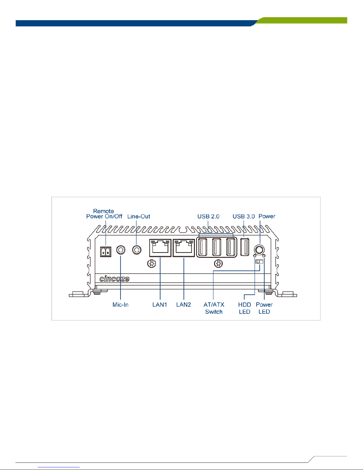
Chapter 1: Product Introductions
Front Panel
Power On/Off Switch
Press to power-on or power-off the system
AT/ATX Mode Select Switch
Used to select AT or ATX power mode
Power LED
Indicates the power status of the system
HDD LED
Indicates the status of the hard drive
Remote Power Terminal Block
Used to plug a remote power on/off switch with
terminal block
USB 3.0 Port
Used to connect USB 3.0/2.0/1.1 device
USB 2.0 Port
Used to connect USB 2.0/1.1 device
LAN Port 1 & 2
Used to connect the system to a local area network
Mic-in
Used to connect a microphone
Line-out
Used to connect a speaker
1.3 System I/O
Page 17
DA-1000 User’s Manual
17
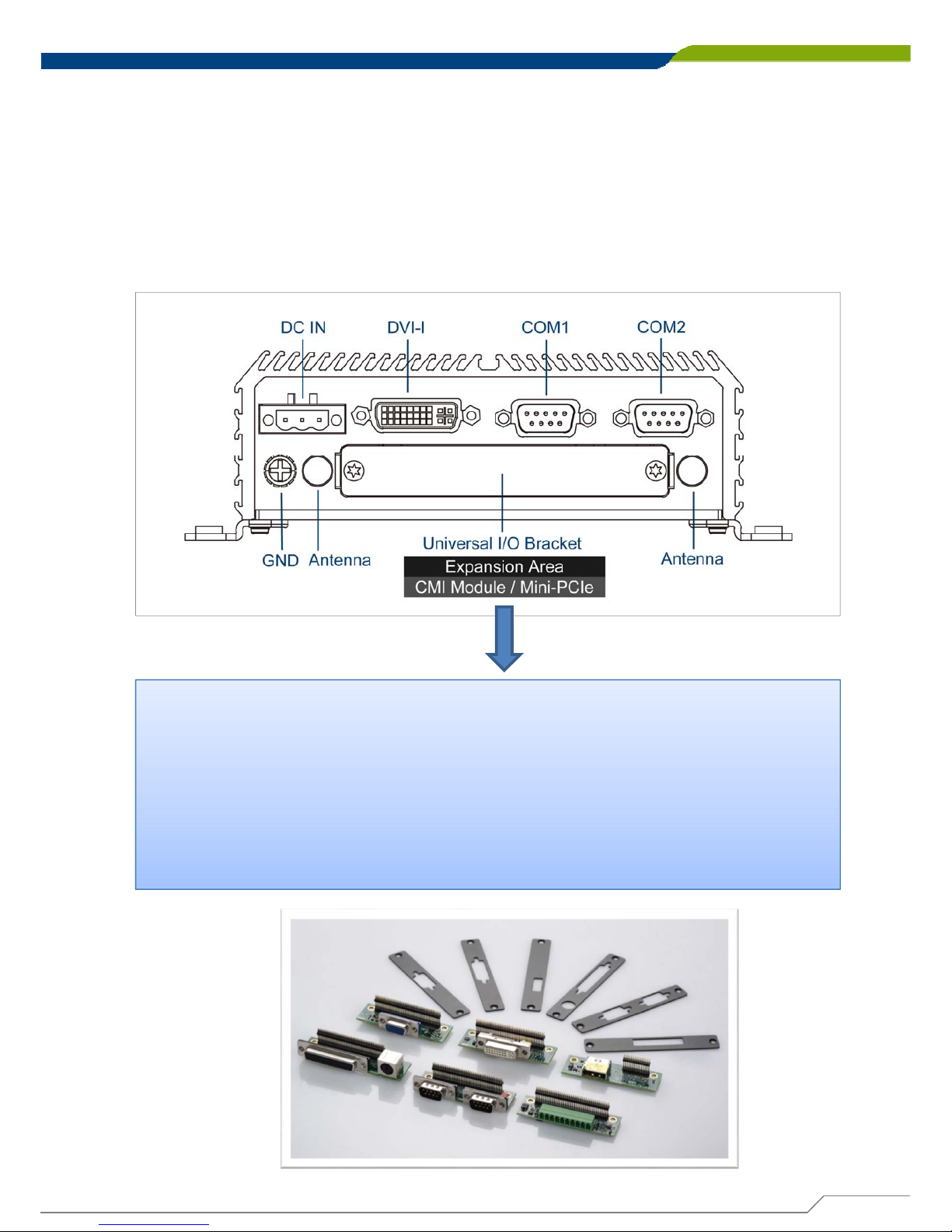
Chapter 1: Product Introductions
Rear Panel
DC IN Terminal Block
Used to plug a DC power input with terminal block
DVI-I Port
Used to connect a DVI monitor or connect optional
split cable for dual display mode
Antenna Hole
Used to connect an antenna for optional Mini-PCIe
WiFi module
COM Port
COM 1 ~ COM 2 support RS232/422/485 serial
device
Universal I/O Bracket
This expansion area is reserved for Mini-PCIe expansion or Cincoze
own pin-defined interface (CMI). CMI interface supports various type
of I/O modules such as COM / DIO / DisplayPort / DVI / LPT & PS2 /
VGA.
Do not change the CMI module by y ourself, it may cause damage to
your DA-1000. Please contact with your regional dealer for more
information about it.
Page 18
DA-1000 User’s Manual
18
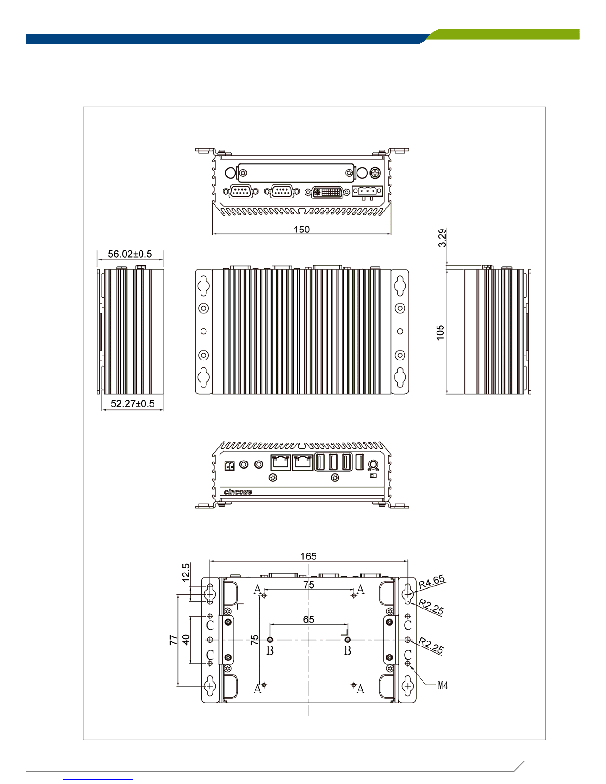
Chapter 1: Product Introductions
1.4 Mechanical Dimensions
Each of DA-1000 series computers has the same mechanical dimension.
Unit: mm
Page 19

Jumpers and Connectors
Chapter 2
Page 20
DA-1000 User’s Manual
20
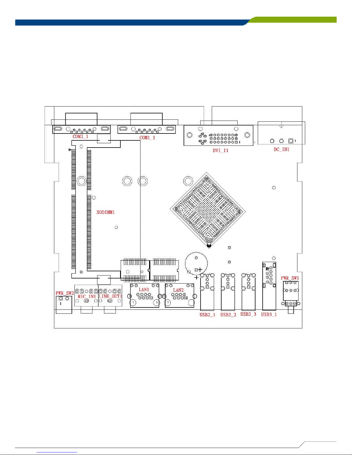
2.1 Jumpers Settings
DA-1000 is featured with jumper-free design.
Chapter 2: Jumpers and Connectors
2.2 Locations of the Switches and Connectors
2.2.1 Top View
Page 21
DA-1000 User’s Manual
21
Chapter 2: Jumpers and Connectors
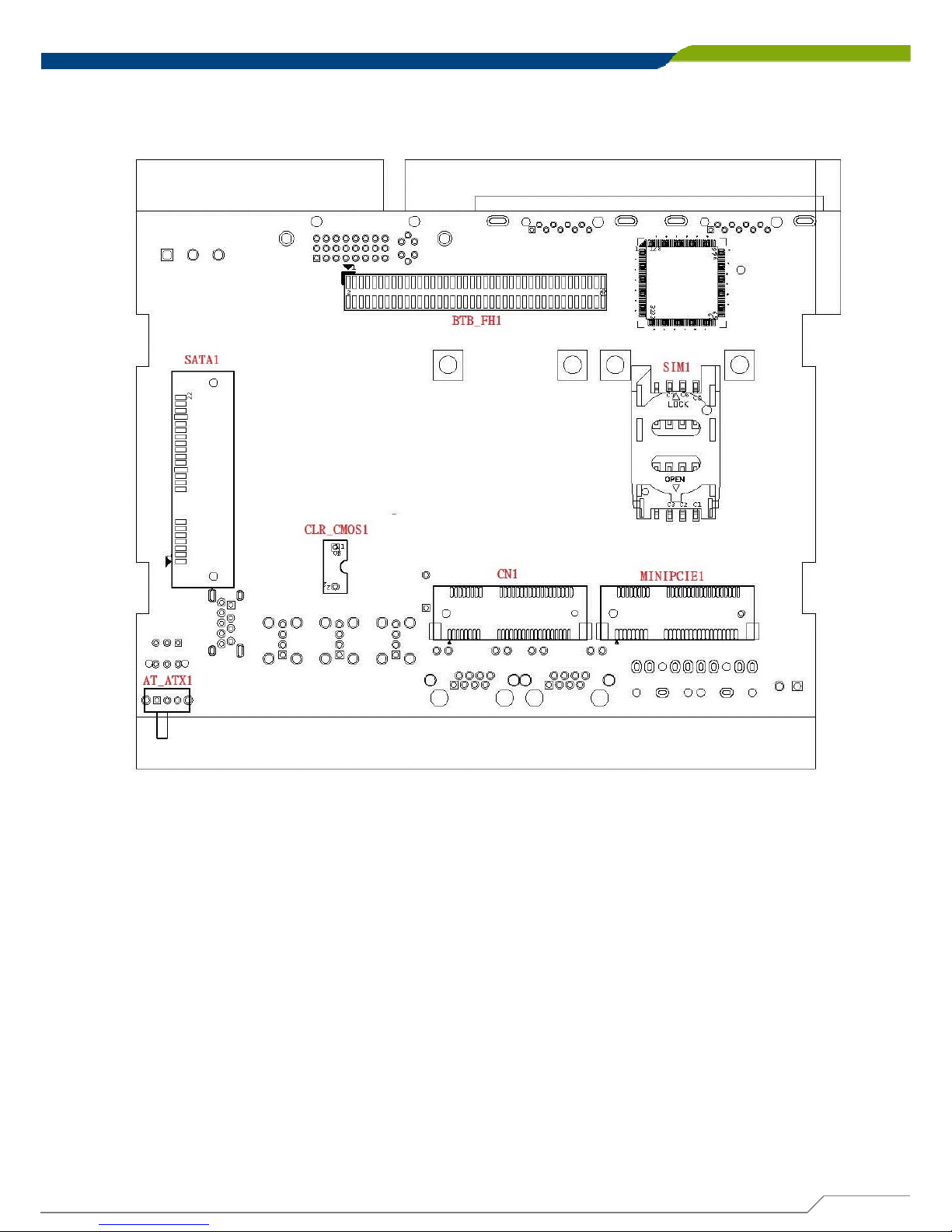
2.2.2 Bottom View
Page 22
DA-1000 User’s Manual
22
Chapter 2: Jumpers and Connectors
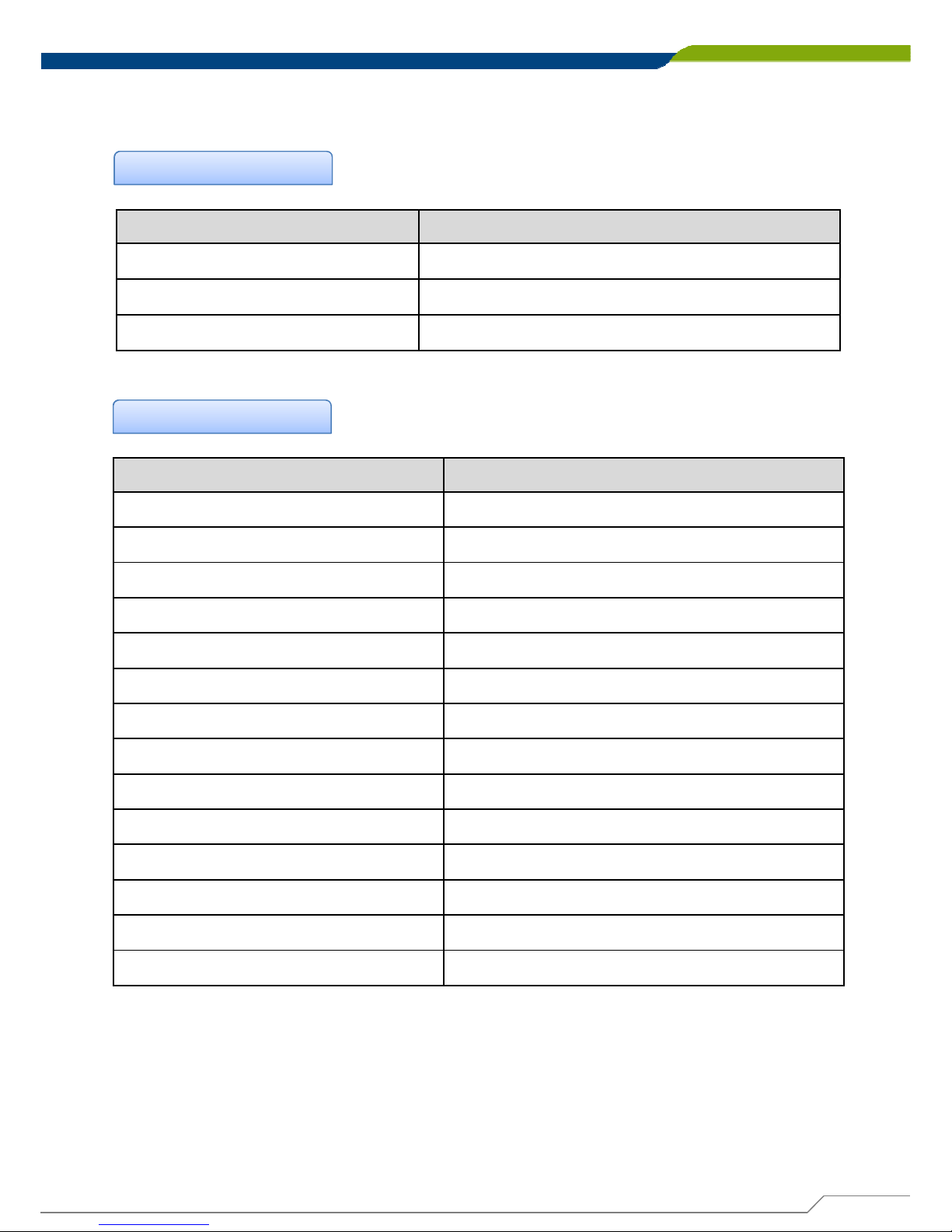
2.3 List of Switches and Connectors
List of Switches
Switches Location Definition
AT_ATX1 AT / ATX Power Mode Switch
CLR_CMOS1 Clear CMOS Switch
PWR_SW1 Power Button
List of Connectors
Connector Location Definition
CN1 Mini PCI-Express / mSATA Socket
COM1_1, COM2_1 RS232 / RS422 / RS485 Connector
DC_IN1 3-pin DC 9~48V Power Connector
DVI_I DVI-I Connector
LAN1 / LAN2 RJ45 with LED Connector
LED Power / HDD Access LED Status
LINE_OUT1 Audio Line-out Jack
MIC_IN1 Microphone-in Jack
MINIPCIE1 Mini PCI-Express Socket
PWR_SW2 External Power Connector
SATA1 SATA with Power Connector
SIM1 SIM Card Socket (apply with MINIPCIE1)
USB2_1 / USB2_2 / USB2_3 USB 2.0 Connector
USB3_1 USB 3.0 Connector
Page 23
DA-1000 User’s Manual
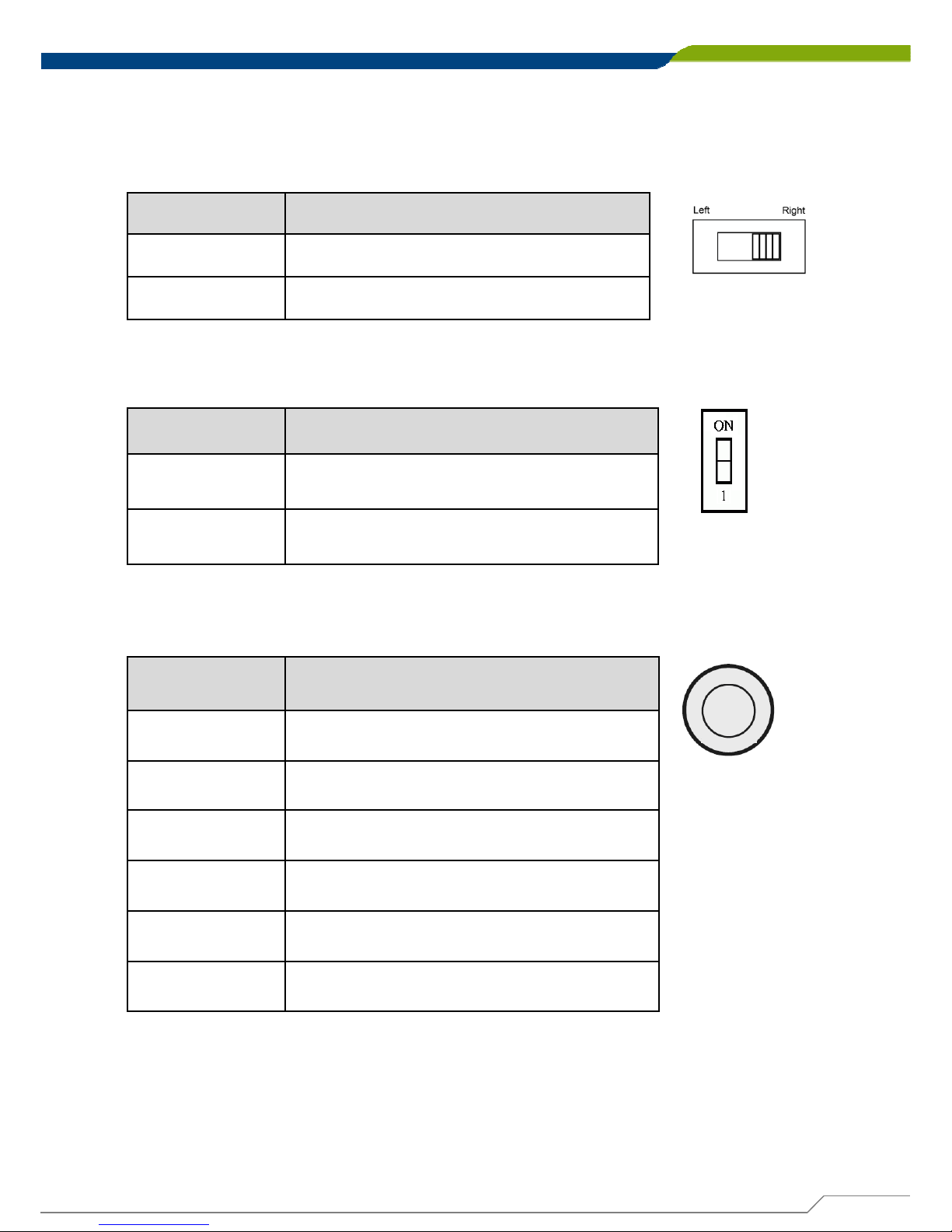
Switch Definition
Right
ATX Power Mode(Default)
Left AT Power Mode
23
Chapter 2: Jumpers and Connectors
2.4 Switches Definitions
AT_ATX1:AT / ATX Power Mode Switch
CLR_CMOS1:Clear CMOS Switch
Switch Definition
ON Clear CMOS
OFF Normal Status (Default)
PWR_SW1:Power Switch
Pin Definition
1NC
2 Power Button
3NC
4GND
5NC
6GND
Page 24
DA-1000 User’s Manual
24
Chapter 2: Jumpers and Connectors
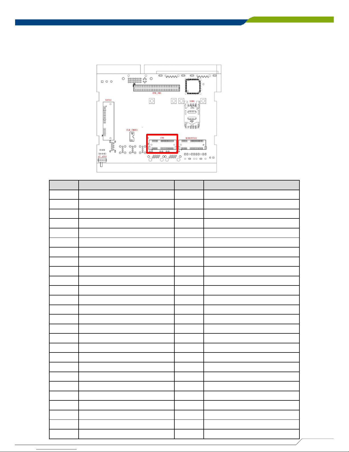
2.5.1 CN1:Mini PCI-Express / mSA TA Socket
2.5 Connectors Definitions
Pin Definition Pin Definition
1 WAKE# 27 GND
2 +3.3V 28 +1.5V
3NC29GND
4 GND 30 SMB_CLK
5 NC 31 MINIPCIE_TXN3/SATA_TXN1
6 +1.5V 32 SMB_DATA
7 CLKREQ# 33 MINIPCIE_TXP3/SATA_TXP1
8NC34GND
9GND35GND
10 NC 36 USB_6N
11 MINIPCIE_CLKN3 37 GND
12 NC 38 USB_6P
13 MINIPCIE_CLKP3 39 +3.3V
14 NC 40 GND
15 GND 41 +3.3V
16 NC 42 NC
17 NC 43 GND
18 GND 44 NC
19 NC 45 NC
20 +3.3V 46 NC
21 GND 47 NC
22 MINIPCIE RST# 48 +1.5V
23 MINIPCIE_RXN3/SATA_RXP1 49 NG
24 +3.3V 50 GND
25 MINIPCIE_RXP3/SATA_RXN1 51 NC
26 GND 52 +3.3V
Page 25
DA-1000 User’s Manual
25
Chapter 2: Jumpers and Connectors
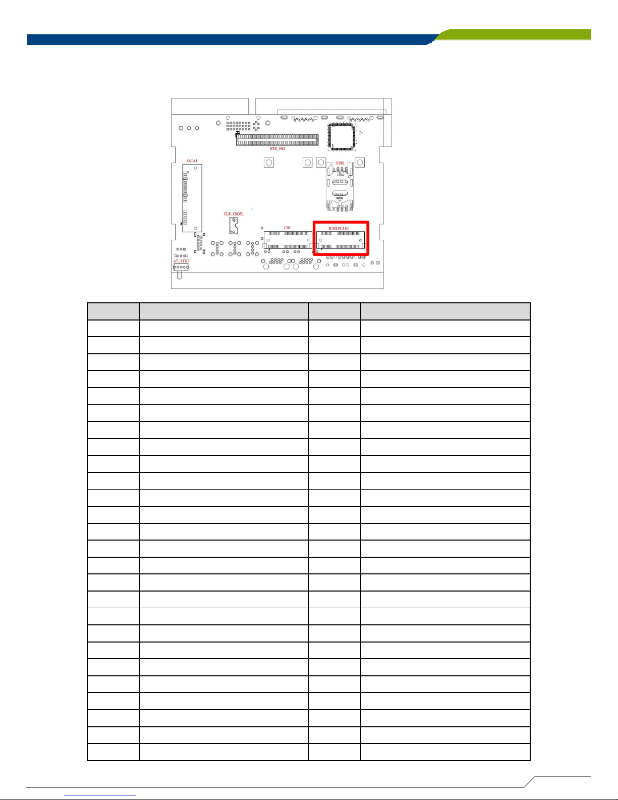
2.5.2 MINIPCIE1:Mini PCI-Express Socket
Pin Definition Pin Definition
1 WAKE# 27 GND
2 +3.3V 28 +1.5V
3NC29GND
4 GND 30 SMB_CLK
5 NC 31 MINIPCIE_TXN4
6 +1.5V 32 SMB_DATA
7 CLKREQ# 33 MINIPCIE_TXP4
8NC34GND
9GND35GND
10 NC 36 USB_7N
11 MINIPCIE_CLKN4 37 GND
12 NC 38 USB_7P
13 MINIPCIE_CLKP4 39 +3.3V
14 NC 40 GND
15 GND 41 +3.3V
16 NC 42 NC
17 NC 43 GND
18 GND 44 NC
19 NC 45 NC
20 +3.3V 46 NC
21 GND 47 NC
22 MINIPCIE RST# 48 +1.5V
23 MINIPCIE_RXN4 49 NC
24 +3.3V 50 GND
25 MINIPCIE_RXP4 51 NC
26 GND 52 +3.3V
Page 26
DA-1000 User’s Manual
26
Chapter 2: Jumpers and Connectors
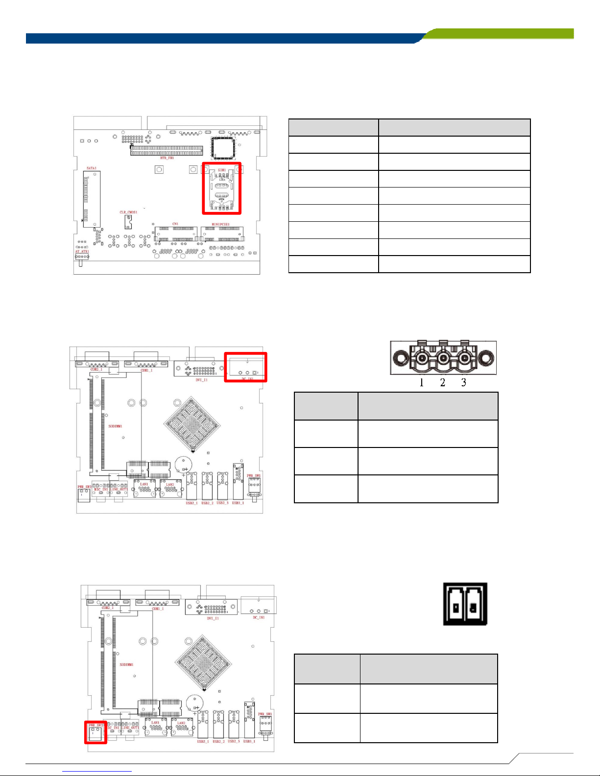
2.5.3 SIM1:SIM Card Socket
Pin Definition
C1 UIM_PWR
C2 UIM_RESET
C3 UIM_CLK
C5 GND
C6 UIM_VPP
C7 UIM_DATA
CD NC
COM GND
2.5.4 DC_IN1:DC Power Input Connector (9~48V)
Connector Type:Phoenix 1X3 3-pin, 5.0mm pitch
Pin Definition
1 +9~48V IN
2 Chassis GND
3GND
Pin Definition
1GND
2PWR_ON
2.5.5 PWR_SW2:External remote power on/off switch
(Note: Please do not apply power to the pins.
This port is used to apply a switch.)
1 2
Page 27
DA-1000 User’s Manual
27
Chapter 2: Jumpers and Connectors
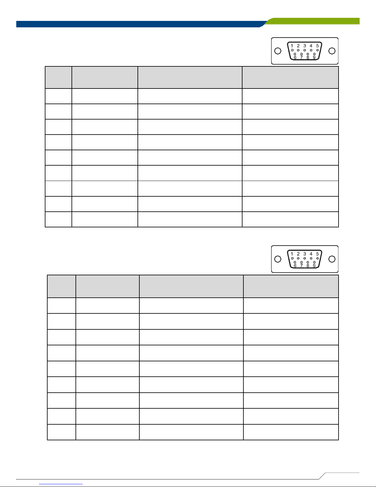
2.5.6 COM1_1:RS232 / RS422 / RS485 Connector
Connector Type:9-pin D-Sub
Pin
RS232
Definition
RS422 / 485
Full Duplex Definition
RS485
Half Duplex Definition
1 DCD1 TX1- DATA1-
2RxD1 TX1+ DATA1+
3TxD1 RX1+ N/A
4DTR1 RX1- N/A
5 GND1 N/A N/A
6DSR1 N/A N/A
7RTS1 N/A N/A
8CTS1 N/A N/A
9RI1 N/A N/A
2.5.7 COM2_1:RS232 / RS422 / RS485 Connector
Connector Type:9-pin D-Sub
Pin
RS232
Definition
RS422 / 485
Full Duplex Definition
RS485
Half Duplex Definition
1 DCD2 TX2- DATA2-
2RxD2 TX2+ DATA2+
3TxD2 RX2+ N/A
4DTR2 RX2- N/A
5 GND2 N/A N/A
6DSR2 N/A N/A
7RTS2 N/A N/A
8CTS2 N/A N/A
9 RI2 N/A N/A
NOTE: (For CMI-COM102 only) The optional CMI module having 2 COM ports
<RS232 / RS422 / RS485> is with +5/+12VDC for RI pin (Pin 9).
Page 28
DA-1000 User’s Manual
28
Chapter 2: Jumpers and Connectors
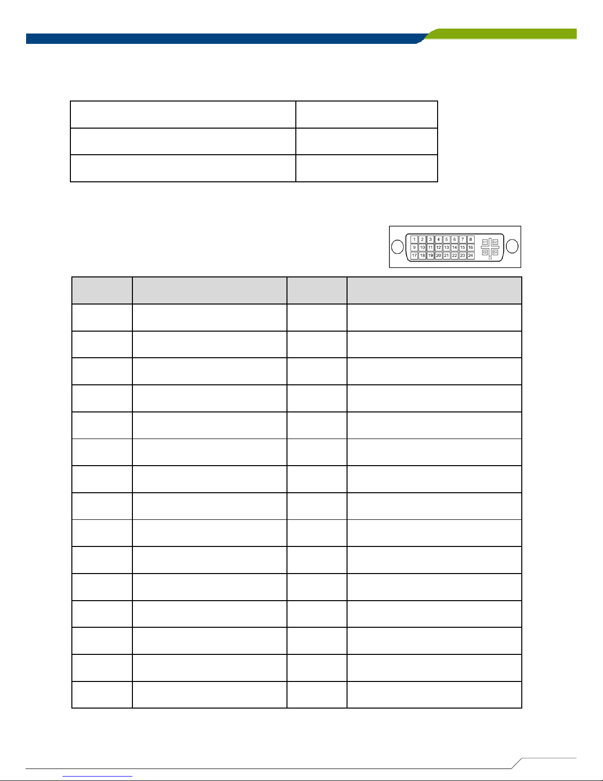
2.5.9 DVI_I1:DVI-I Connector
Pin Definition Pin Definition
1 DVI_TX2- 16 DVI Hot Plug Detect
2 DVI_TX2+ 17 DVI_TX0-
3 GND 18 DVI_TX0+
4NC19 GND
5NC20 NC
6 DDC_CLOCK 21 NC
7 DDC_DATA 22 GND
8 VGA VSYNC 23 DVI_TXCLK+
9 DVI_TX1- 24 DVI_TXCLK-
10 DVI_TX1+ C1 VGA_RED
11 GND C2 VGA_GREEN
12 NC C3 VGA_BLUE
13 NC C4 VGA_HSYNC
14 +5V C5 GND
15 GND
2.5.8 COM3、COM4:Voltag e Select
PIN 1-3, PIN 2-4 5V
PIN 3-5, PIN 4-6 12V
PIN 7-9, PIN 8-10 RI (Default)
Page 29
DA-1000 User’s Manual
29
Chapter 2: Jumpers and Connectors
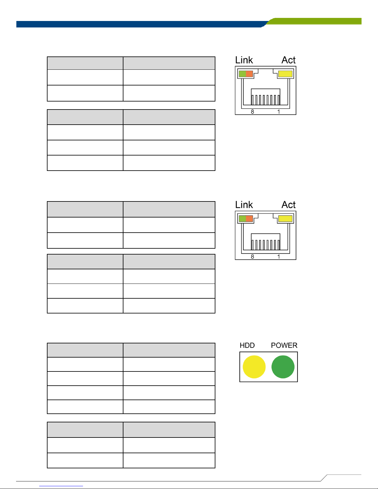
2.5.10 LAN1:RJ45 with LED Connector
Act LED Status Definition
Blinking Yellow Data Activity
Off No Activity
2.5.1 1 LAN2:RJ45 with LED Connector
Act LED Status Definition
Blinking Yellow Data Activity
Off No Activity
2.5.12 LED1:Power / HDD Access LED Status
Pin Definition
1 HDD LED+
2 HDD LED-
3POWER LED+
4POWER LED-
LED Status LED Color
HDD Yellow
POWER Green
Link LED Status Definition
Steady Green 1Gbps Network Link
Steady Amber 100Mbps Network Link
Off 10Mbps Network Link
Link LED Status Definition
Steady Green 1Gbps Network Link
Steady Amber 100Mbps Network Link
Off 10Mbps Network Link
Page 30
DA-1000 User’s Manual
30
Chapter 2: Jumpers and Connectors
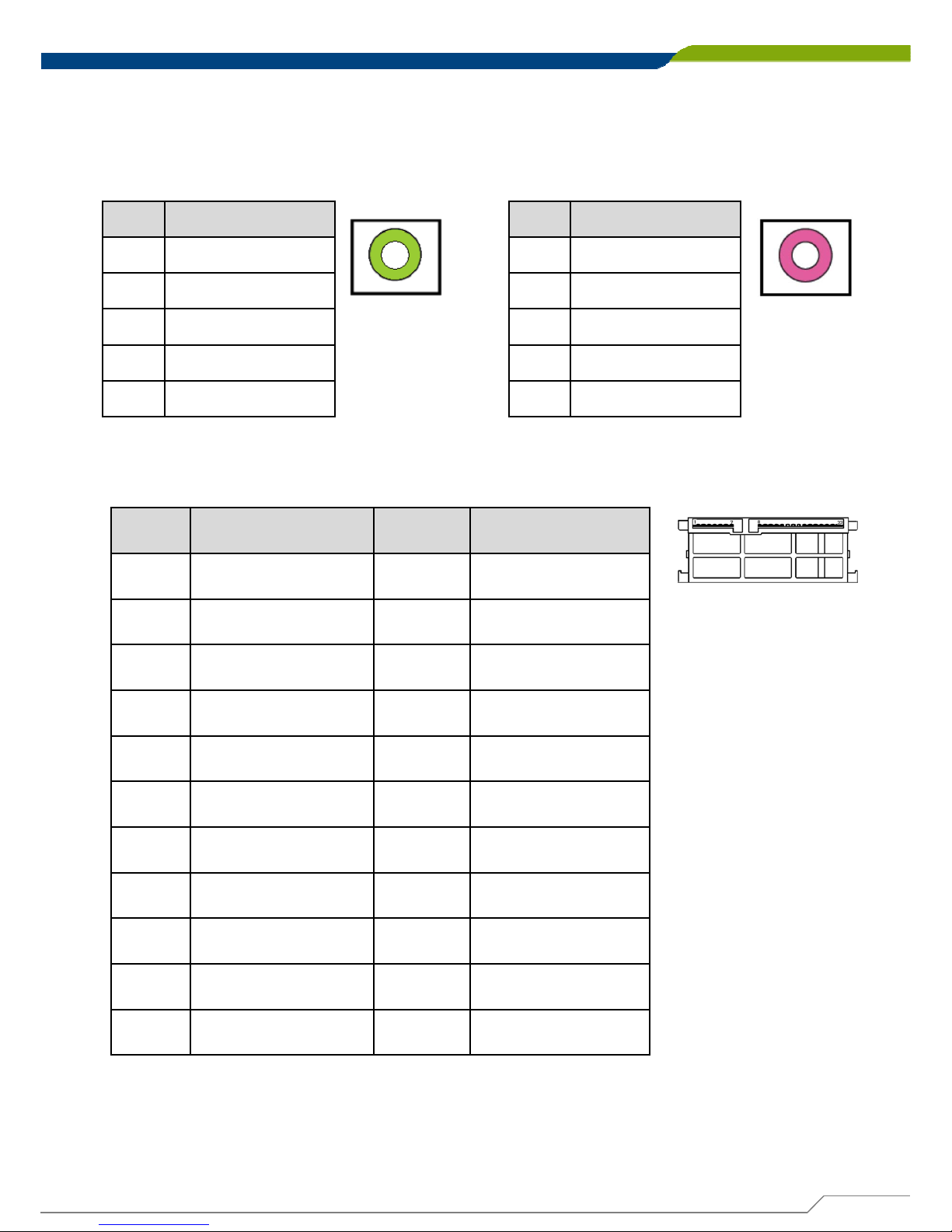
2.5.13 LINE_OUT1:
Line-out Jack (Green)
Connector Type:5-pin Phone Jack
Pin Definition
1GND
2OUT_R
3NC
4GND
5OUT_L
2.5.14 MIC1:
Microphone Jack (Pink)
Connector Type:5-pin Phone Jack
Pin Definition
1GND
2MIC_R
3NC
4GND
5MIC_L
2.5.15 SA TA1:SATA Connector
Pin Definition Pin Definition
1GND 12GND
2TX+ 13GND
3TX-14+5V
4 GND 15 +5V
5RX-16+5V
6RX+ 17GND
7GND 18GND
8 +3.3V 19 GND
9 +3.3V 20 +12V
10 +3.3V 21 +12V
11 GN D 2 2 +12 V
Page 31
DA-1000 User’s Manual
31
Chapter 2: Jumpers and Connectors
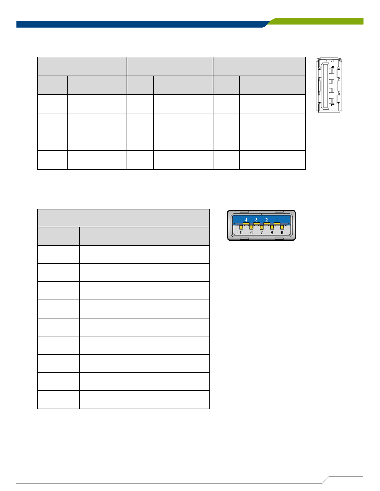
2.5.16 USB2_1、USB2_2 、 USB2_3:USB2.0 Connector, Type A
USB2_1 USB2_2 USB2_3
Pin Definition Pin Definition Pin Definition
1 +5V 1 +5V 1 +5V
2 USB_DATA3- 2 USB_DATA2- 2 USB_DATA1-
3 USB_DATA3+ 3 USB_DATA2+ 3 USB_DATA1+
4 GND 4 GND 4 GND
2.5.17 USB3_1:USB3.0 Connector, Type A
USB4
Pin Definition
1+5V
2 USB3_DATA0-
3 USB3_DATA0+
4GND
5 USB3_Rx0-
6 USB3_Rx0+
7GND
8 USB3_Tx0-
9 USB3_Tx0+
Page 32

System Setup
Chapter 3
Page 33
DA-1000 User’s Manual
33
Chapter 3: System Setup
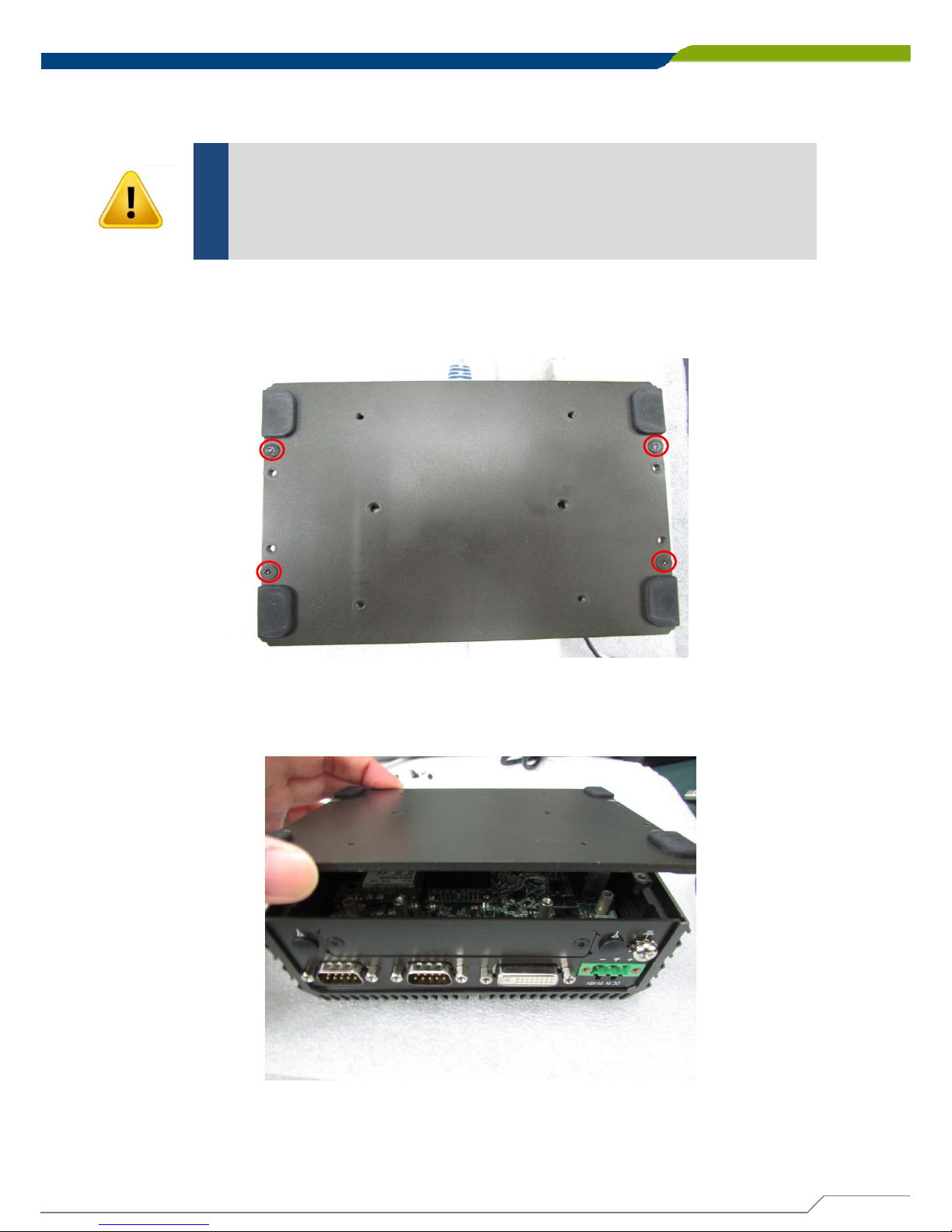
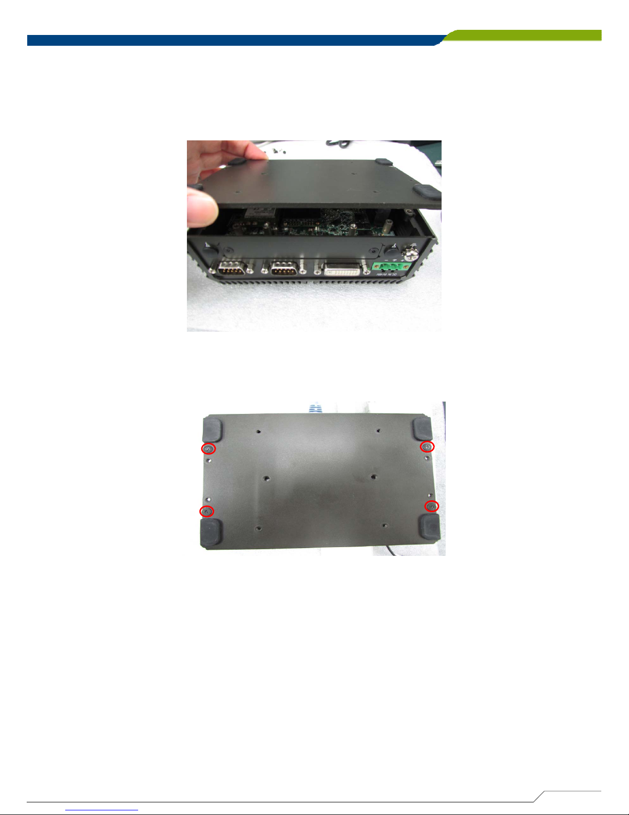
1. Turn over the unit to have the bottom side face up, loosen the 4 screws of bottom
cover and place them aside.
3.1 Removing the Chassis Bottom Cover
In order to prevent electric shock or system damage, before
removing the chassis cover, must turn off power and disconnect
the unit from power source.
WARNING
2. Remove the cover from the chassis.
Page 34
DA-1000 User’s Manual
34
Chapter 3: System Setup
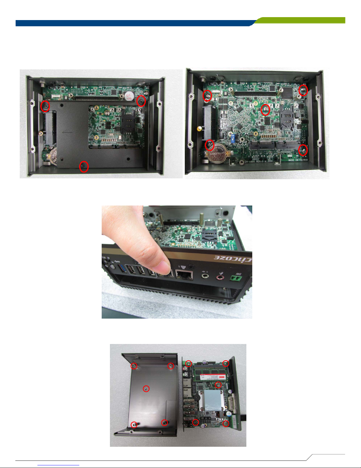
3.2 Removing the Chassis
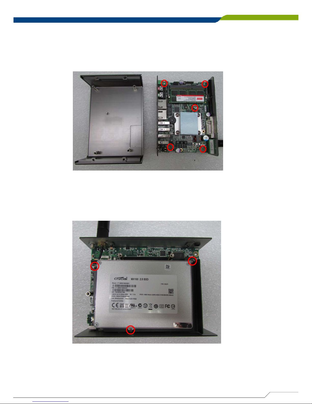
1. Loosen the 3 screws (left picture) and remove HDD base plate. Loosen the 5
screws (right picture) as marked on photo and place them aside.
2. Hold front and rear panel and lift up the body of unit vertically.
3. Turn over the body of the unit and place it gently.
Page 35
DA-1000 User’s Manual
35
Chapter 3: System Setup
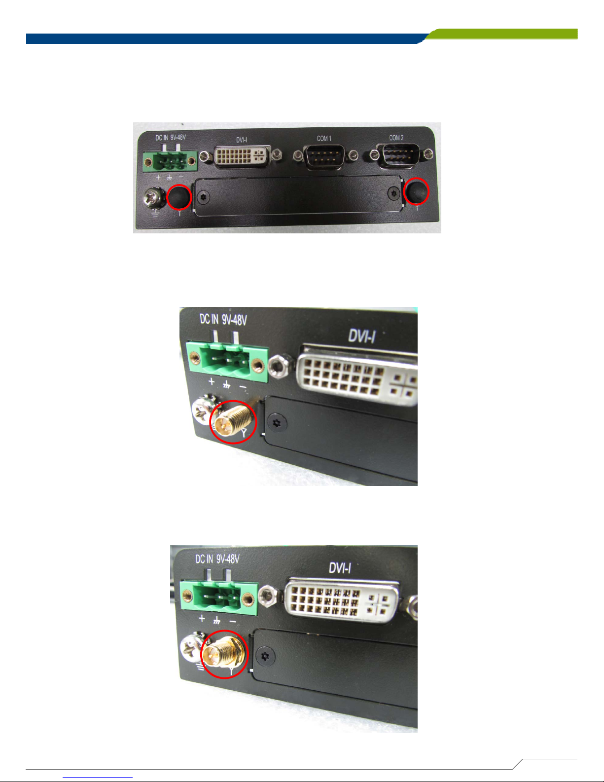
3.3 Installing the Antennas
1. Remove the antenna hole covers at back panel.
2. Have antenna jack penetrate through the hole.
3. Put on washer and fasten the nut with antenna jack.
Page 36
DA-1000 User’s Manual
36
Chapter 3: System Setup
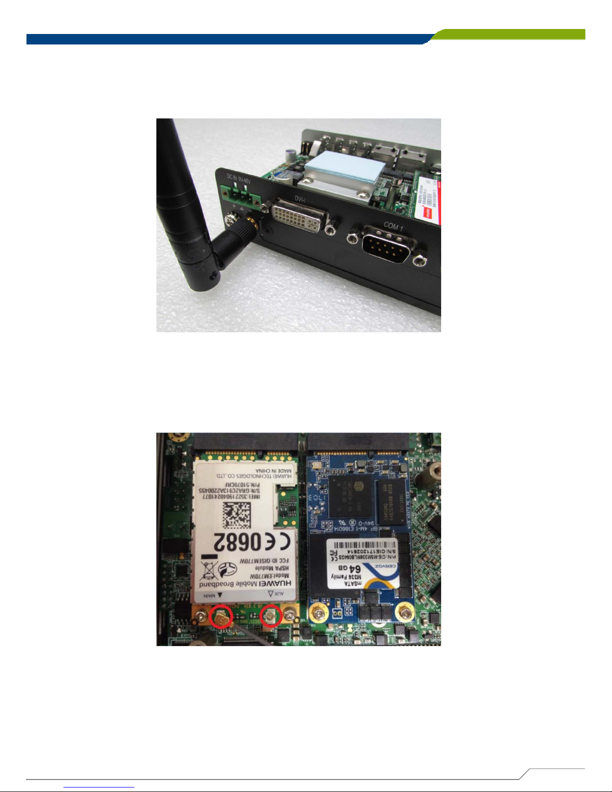
4. Assemble the antenna and antenna jack together.
5. Attach the RF connector at another end of cable onto the module.
Page 37
DA-1000 User’s Manual
37
Chapter 3: System Setup
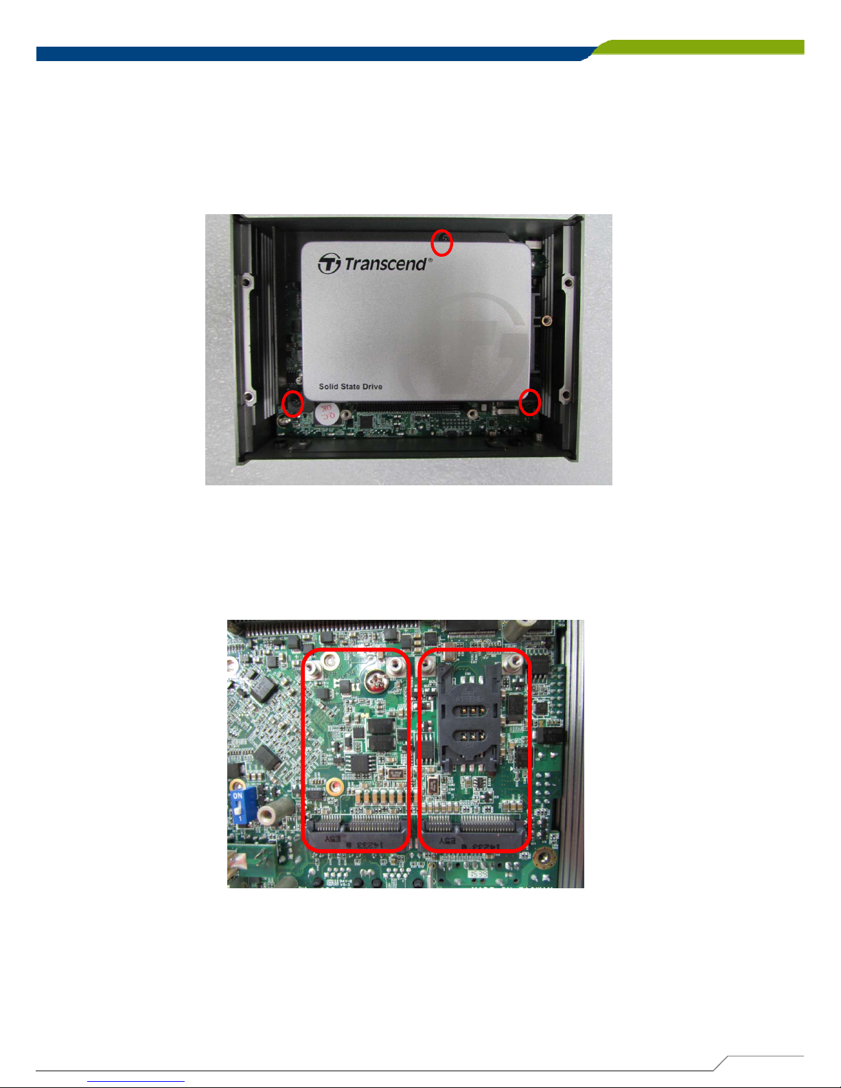
3.4 Installing a Full-Size Mini PCIe Card on Bottom Side,
including Half-Size Mini PCIe card
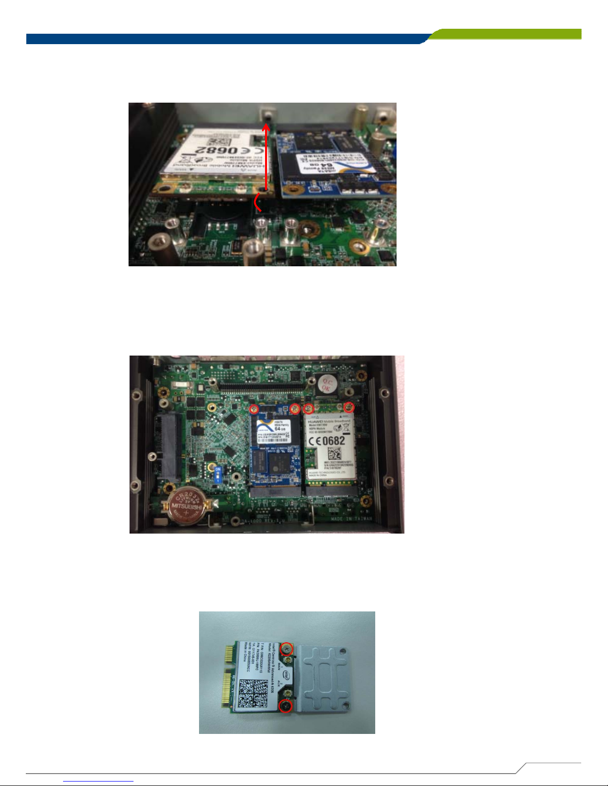
1. Turn over the body of unit. Unscrew the 3 screws on HDD bracket and remove the
bracket.
2. Locate the Mini PCIe slots. Please note that the left connector is shared
mSATA/Mini-PCIe interface, and right connector (with SIM socket underneath) is
Mini-PCIe interface.
Page 38
DA-1000 User’s Manual
38
Chapter 3: System Setup
3. Tilt the Mini PCIe modules at 45 degree angle and insert it to the slot until the goldpated connector of module contacted firmly with the slot.
4. Press down the module and use the two screws to fix the module.
5. If you have a Half-size Mini-PCIe card, make sure use extender to make it Full-size
as shown below.
45°
Page 39
DA-1000 User’s Manual
39
Chapter 3: System Setup
3.5 Installing a SATA Hard Drive
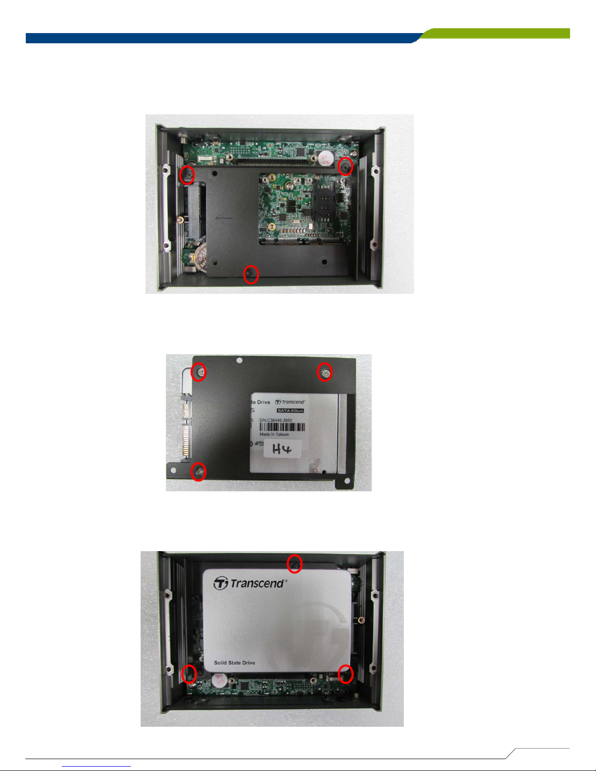
1. Lift up the empty HDD bracket by unscrewing the 3 screws.
2. Make the PCB side of the HDD face up, place the HDD bracket on it. Ensure the
direction of bracket is correct and use 3 provided screws to assemble HDD and
HDD bracket together.
3. Turn over the HDD bracket. Connect the HDD bracket to the SATA connector of the
unit and fasten the 3 screws.
Page 40
DA-1000 User’s Manual
40
Chapter 3: System Setup
3.6 Installing a SODIMM
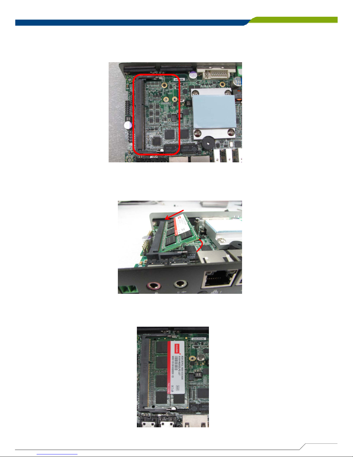
1. Locate SODIMM socket.
2. Tilt the SODIMM module at a 45 degree angle and insert it to SODIMM socket until
the gold-pated connector of module contacted firmly with the socket.
45°
3. Press the module down until it’s fixed firmly by the two locking latches on the sides.
Page 41
DA-1000 User’s Manual
41
Chapter 3: System Setup
3.7 Installing the Chassis
1. Hold the body of unit, level the 5 screw holes with the hollow studs on the chassis.
2. Make sure the either sides of front and rear panels are in the chassis grooves and
insert the body of unit into Chassis. Use the 3 screws to fasten the body and chassis
together.
Page 42
DA-1000 User’s Manual
42
Chapter 3: System Setup
3.8 Installing the Chassis Bottom Cover
1. Level the grooves on bottom cover with front and rear panels. Put on the cover.
2. Fasten the 4 screws to fix the cover.
Page 43
DA-1000 User’s Manual
43
Chapter 3: System Setup
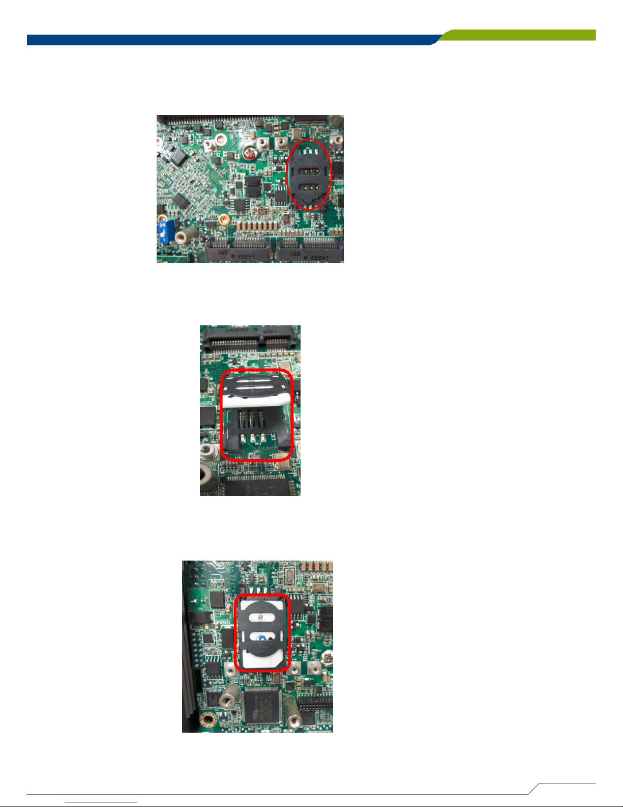
3.9 Installing a SIM Card
1. Locate the SIM card socket.
2. Insert the SIM card.
3. Press down the socket of SIM card to lock the location.
Page 44
DA-1000 User’s Manual
44
Chapter 3: System Setup
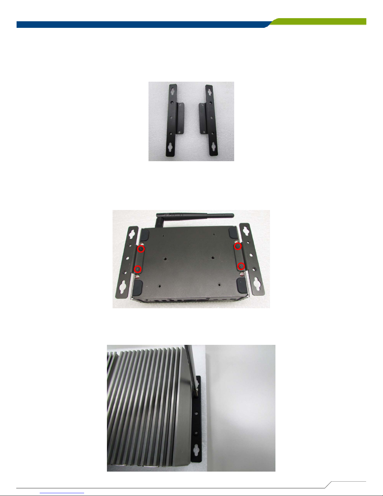
3.10 Wall Mount Brackets
1. The mounting holes are at the bottom of system. Use provided 4 screws to fasten
the bracket with each side of system together.
DA-1000 offers Wall Mount that customers can install system on the wall in convenient
and economical way.
2. Fasten the screws through the bracket mounting hole to mount system on the wall.
Page 45
DA-1000 User’s Manual
45
Chapter 3: System Setup
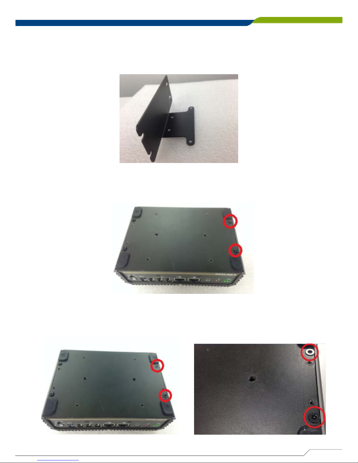
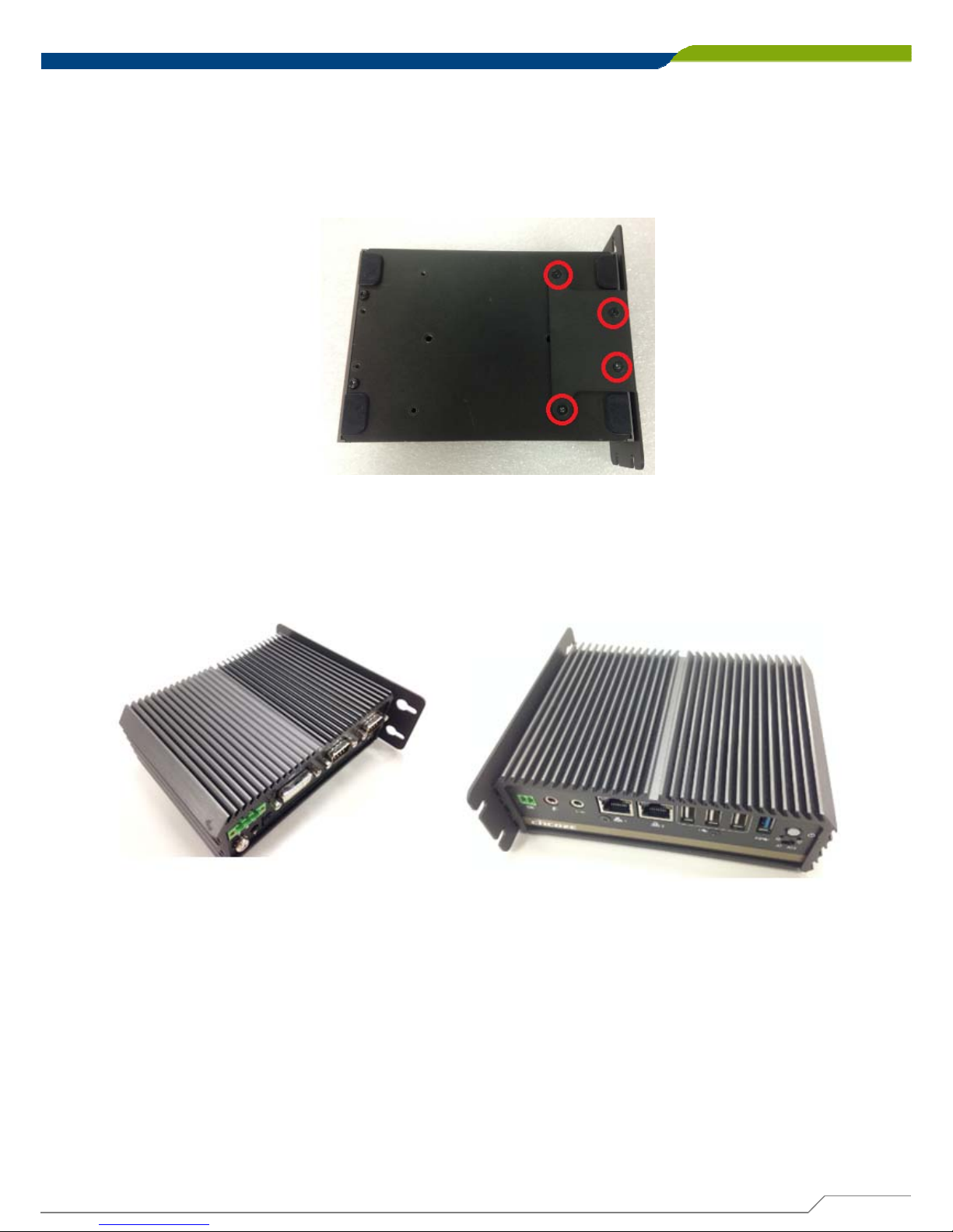
3.11 Side Mount Bracket
1. The mounting holes are at the bottom of system. Remove the 2 screws at right side
of bottom plate.
DA-1000 offers Side Mount that customer can install system to the right or left side of
wall to create effective of space.
2. Replace them with 2 longer flat-head screws that come with the side mount
screw pack.
Page 46
DA-1000 User’s Manual
46
4. Fasten the screws through the bracket mounting hole to mount system on the wall.
3. Place the side mount bracket on bottom of system as picture below, and fasten the
rest of 4 screws to fix it with system together.
Page 47
DA-1000 User’s Manual
47
Chapter 3: System Setup
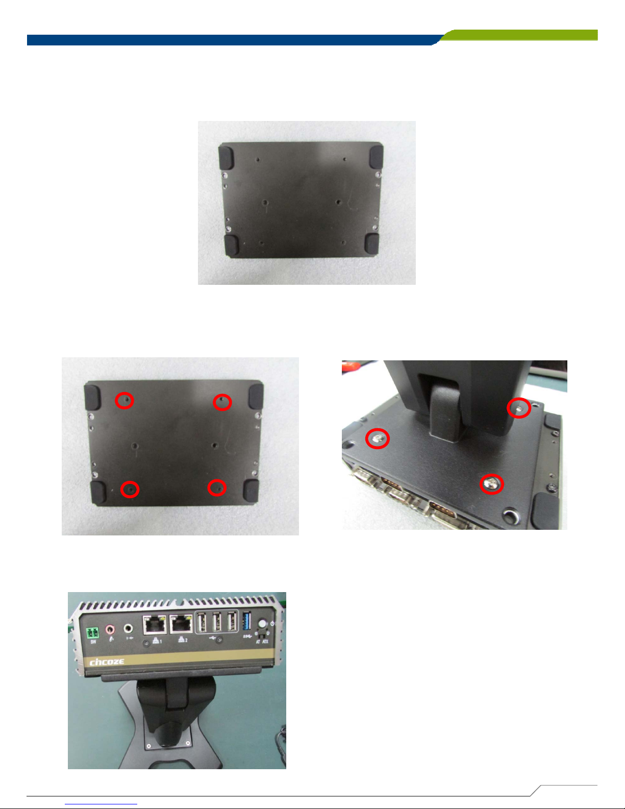
3.13 VESA Mount Brackets
1. Provided below is the base of the
system unit and screw holes specified
to be mounted from VESA stand.
DA-1000 offers VESA Mount that customer can mount system with panel complying
with VESA 75mm and 100 mm standard for various usage.
2. Provided below is mounted with VESA
stand.
3. Provided below is completion of mounting with VESA stand.
Page 48
DA-1000 User’s Manual
48
Chapter 3: System Setup
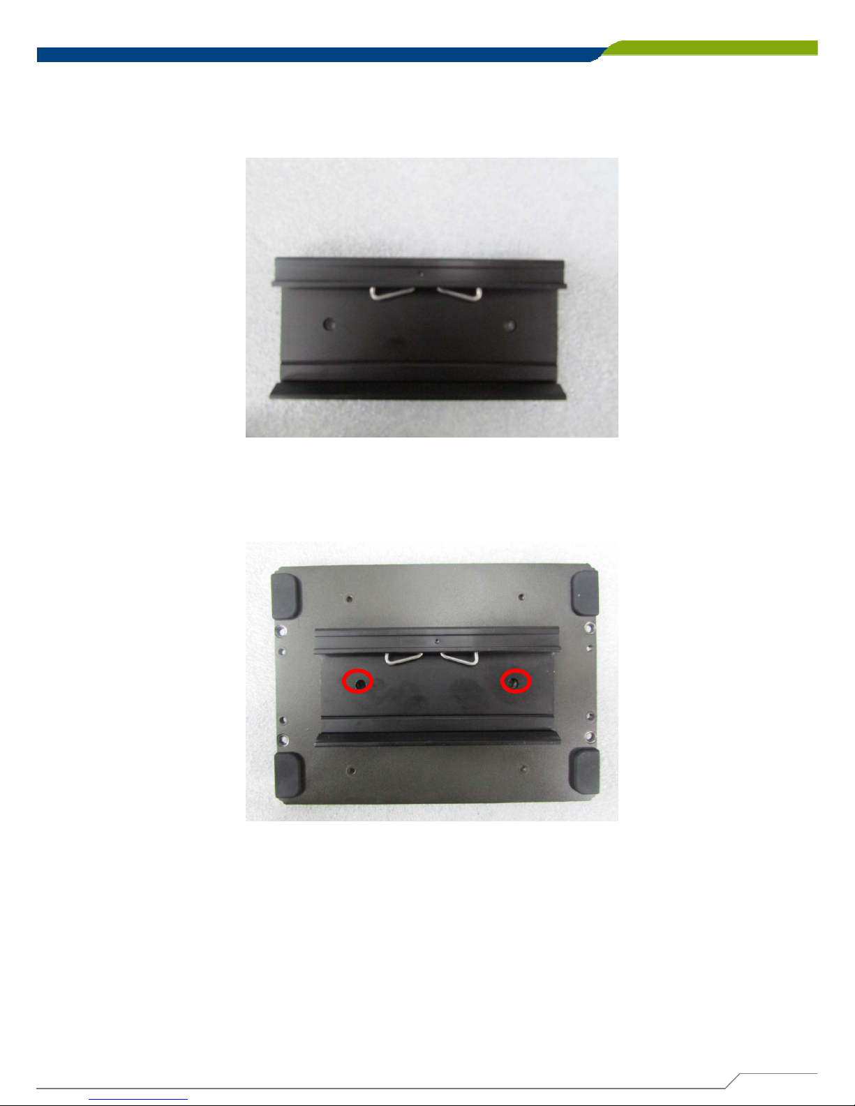
3.14 DIN-Rail Mount Bracket
DA-1000 offers DIN-Rail Mount that customer can install system on the DIN Rail.
1. The mounting holes are at the bottom of system. Fasten the 2 screws to fix the DINRail mount bracket with system together.
Page 49

BIOS Setup
Chapter 4
Page 50
DA-1000 User’s Manual
Chapter 4: BIOS Setup
4.1 BIOS Introduction
BIOS (Basic Input/Output System) is a program located on a Flash Memory on the
motherboard. When you start the computer, the BIOS program will gain control. The
BIOS first operates an auto-diagnostic test called POST (power on self test) for all the
necessary hardware, it detects the entire hardware device and configures the
parameters of the hardware synchronization.
4.1.1 BIOS Setup
Power on the computer, and pressing <Del> key immediately allows you to enter BIOS
Setup. If the message disappears before you respond and you still wish to enter Setup,
restart the system to try again by turning the system OFF and then ON, or pressing
<Ctrl>+<Alt>+<Delete> keys simultaneously.
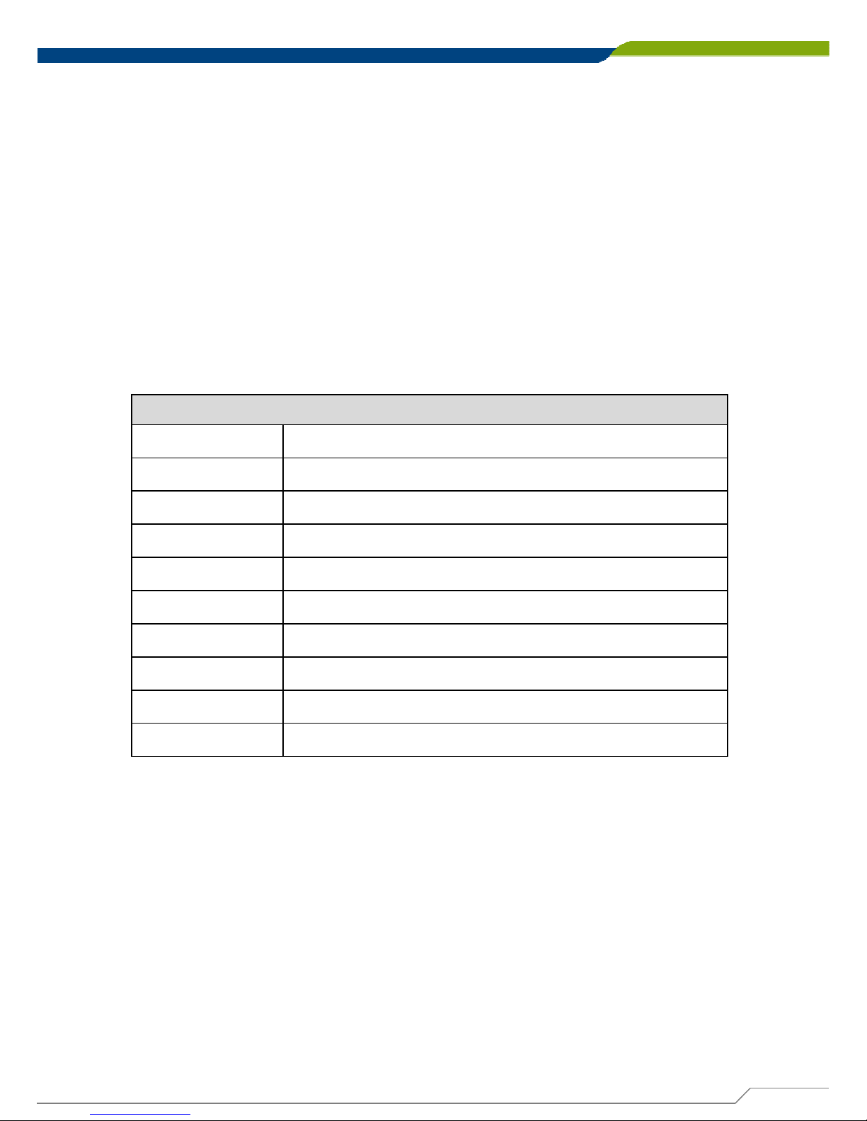
Below is table of keys used in BIOS setup.
Control Keys
<↑> <↓> <←> <→> Move to select screen
<Enter> Select item
<Esc> Quit the BIOS Setup
<+> Increases the numeric value or makes changes
<-> Decreases the numeric value or makes changes
<Tab> Select setup fields
<F1> General help
<F7> Select boot device
<F9> Load Optimized defaults
<F10> Save configuration and Exit
4.1.2 Main Menu
The main menu lists the setup functions you can make changes to. You can use the
arrow keys ( ↑↓ ) to select the item. The on-line description of the highlighted setup
function is displayed at the bottom of the screen. On the upper right box there is online
help for the field to be changed.
4.1.3 Sub-Menu
If you find a right pointer symbol appears to the left of certain fields that means a submenu can be launched from this field. A sub-menu contains additional options for a
field parameter. You can use arrow keys ( ↑↓ ) to highlight the field and press <Enter>
to call up the sub-menu. Then you can use the control keys to enter values and move
from field to field within a sub-menu. If you want to return to the main menu, just press
the <Esc>.
50
Page 51
DA-1000 User’s Manual
Chapter 4: BIOS Setup
4.2 Main Setup
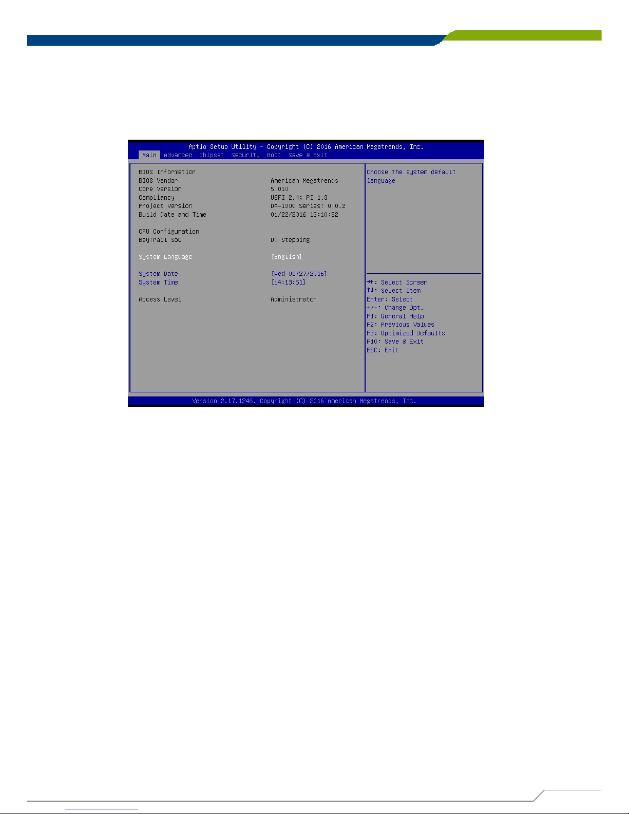
Press <Del> to enter BIOS CMOS Setup Utility, the Main Menu (as shown below) will
appears on the screen. Use arrow keys to move among the items and press <Enter> to
accept or enter a sub-menu.
4.2.1 System Date
Set the date. Please use <Tab> to switch between time elements.
4.2.2 System Time
Set the time. Please use <Tab> to switch between date elements.
51
Page 52
DA-1000 User’s Manual
Chapter 4: BIOS Setup
4.3 Advanced Setup
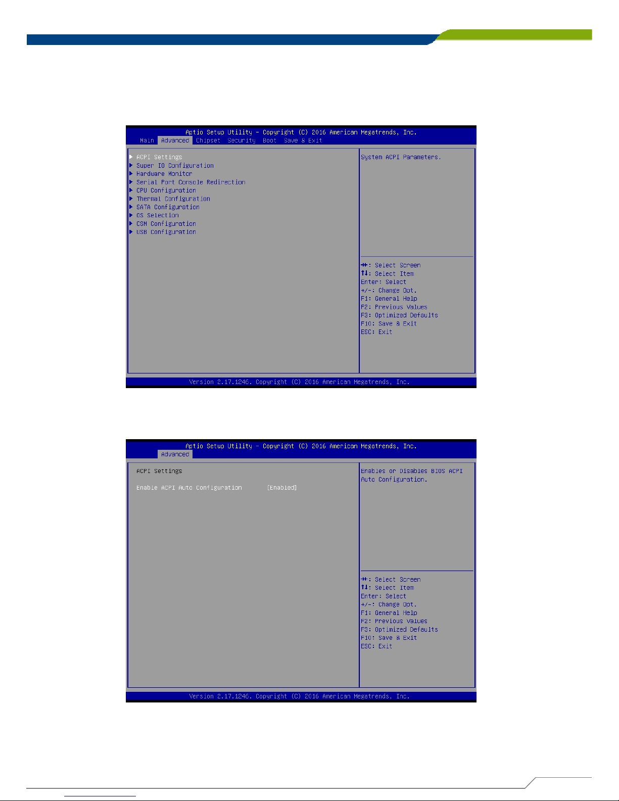
The Advanced menu allows users to set configuration of the CPU and other system
devices. You can select any of the items in the left frame of the screen to go to the sub
menus.
4.3.1 ACPI Settings
■ Enable ACPI Auto Configuration
This enables ACPI power management of the system.
52
Page 53
DA-1000 User’s Manual
53
Chapter 4: BIOS SetupChapter 4: BIOS Setup
4.3.2 Super I/O Configuration
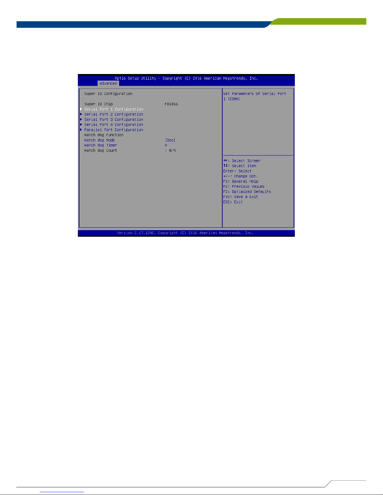
This allows you to configure legacy ports such as serial and parallel ports. It also
has watch dog function embedded in the Super I/O chip.
■ Serial Port 1 Configuration
This allows you to configure serial port 1.
■ Serial Port 2 Configuration
This allows you to configure serial port 2.
■ Serial Port 3 Configuration
This allows you to configure serial port 3.
■ Serial Port 4 Configuration
This allows you to configure serial port 4.
We’ll use serial port 1 configuration as an example in the manual. Similar settings
apply to other serial ports configuration.
Page 54
DA-1000 User’s Manual
54
Chapter 4: BIOS SetupChapter 4: BIOS Setup
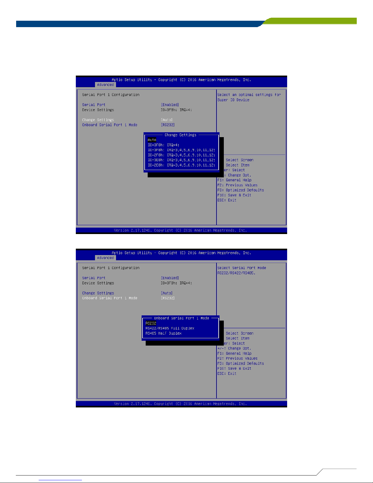
Entering serial port 1 configuration allows you to enable or disable the port ,and
also to configure settings and mode of operations. To avoid conflicted setting with
other serial ports, default setting is recommended.
Page 55
DA-1000 User’s Manual
55
Chapter 4: BIOS SetupChapter 4: BIOS Setup
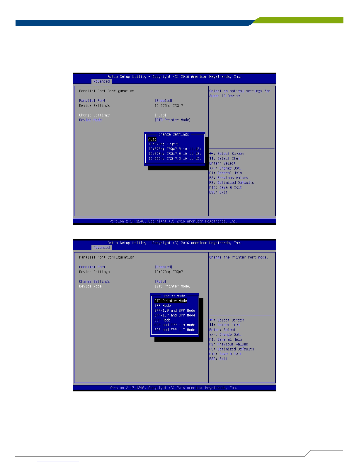
Entering parallel port configuration allows you to enable or disable the port ,and
also to configure settings and mode of device operation. Default setting is
recommended.
Page 56
DA-1000 User’s Manual
56
Chapter 4: BIOS SetupChapter 4: BIOS Setup
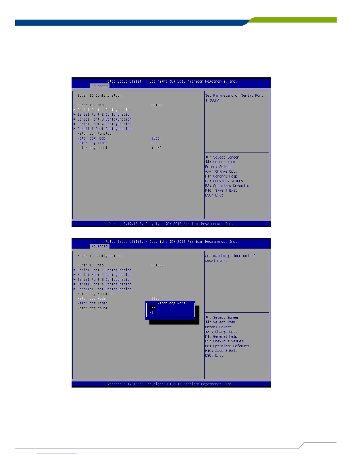
Watch dog timer allows you to set timer and count down time in seconds or
minutes to reset the system via hardware. If you have set a timer value, the
system will reset the system in accordance with the timer value set, regardless of
existence and state of Operating System.
■ Watch dog Mode
This allows you to set the timer unit in seconds or minutes.
■ Watch dog Timer
This allows you to set between 0 and 255 in unit that was set in Watch dog Mode.
Page 57
DA-1000 User’s Manual
57
Chapter 4: BIOS SetupChapter 4: BIOS Setup
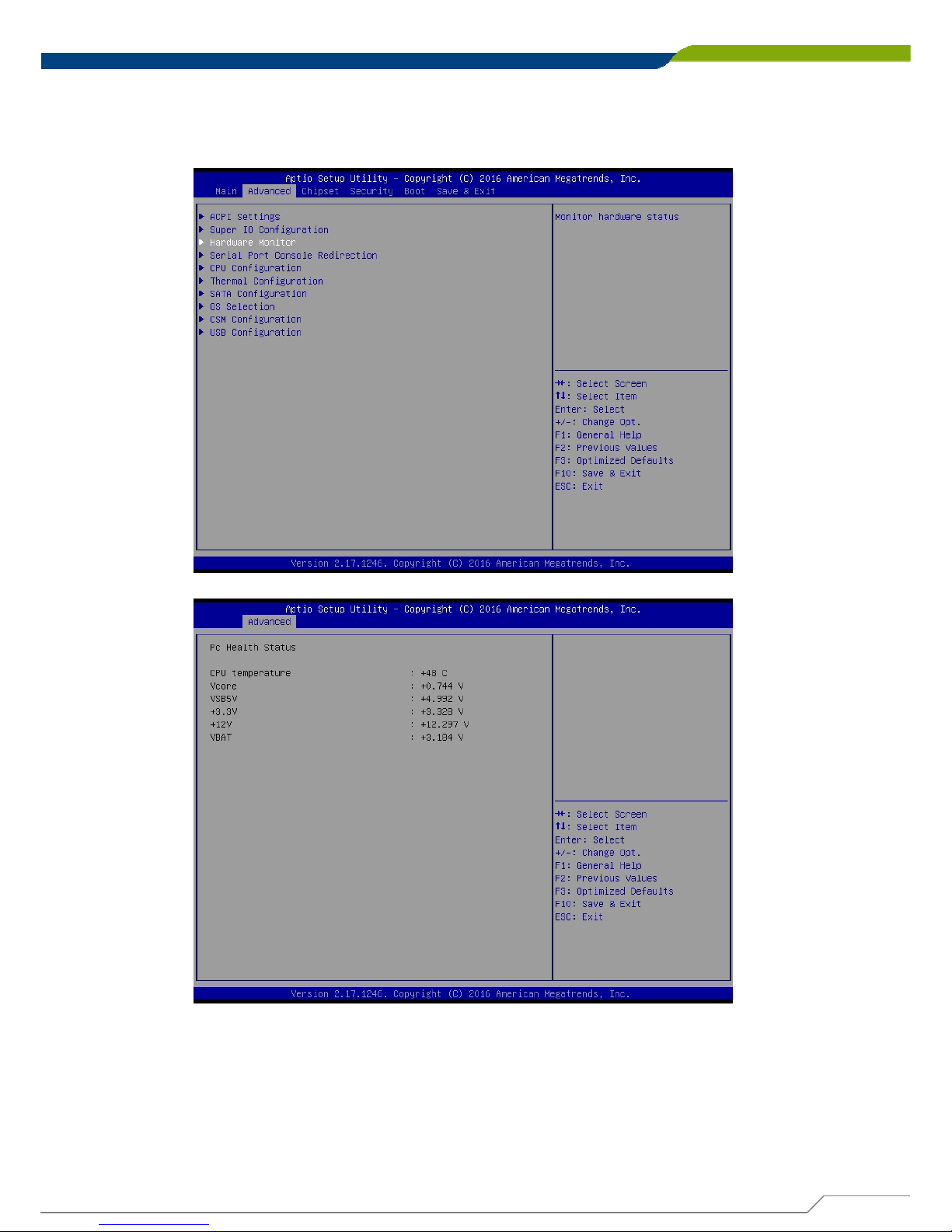
4.3.3 Hardware Monitor
This allows you to monitor system’s CPU temperature and voltages.
Page 58
DA-1000 User’s Manual
58
Chapter 4: BIOS SetupChapter 4: BIOS Setup
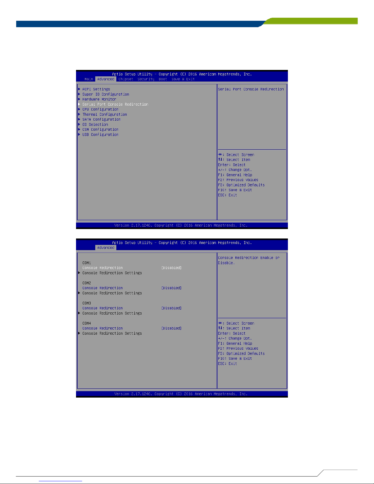
4.3.4 Serial Port Console Redirection
This allows you to enable and disable serial (COM) port(s) for console use.
Default setting is disabled.
Page 59
DA-1000 User’s Manual
59
Chapter 4: BIOS SetupChapter 4: BIOS Setup
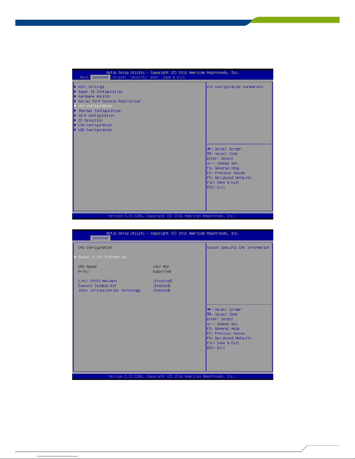
4.3.5 CPU Configuration
This allows you to configure CPU settings such as enabling or disabling of Intel
virtualization technology. Use of default setting is recommended in the section.
■ Limit CPUID Maximum
Default is Disabled.
■ Execute Disable Bit
Default is Enabled.
■ Intel Virtualization Technology
Default is Enabled.
Page 60
DA-1000 User’s Manual
60
Chapter 4: BIOS SetupChapter 4: BIOS Setup
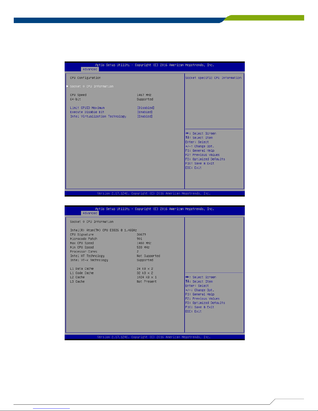
Entering Socket 0 CPU Information shows CPU hardware details and supported
features.
Page 61
DA-1000 User’s Manual
61
Chapter 4: BIOS SetupChapter 4: BIOS Setup
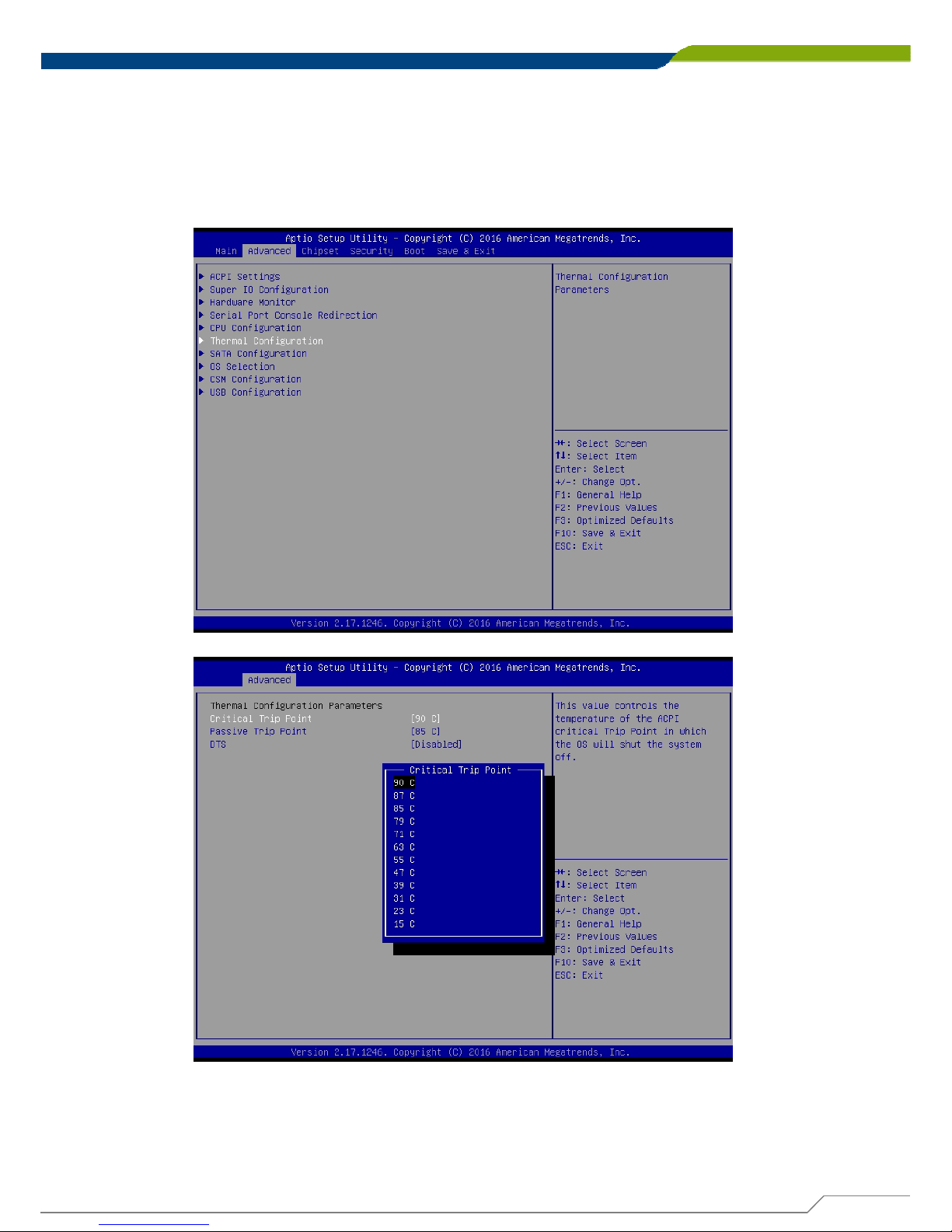
4.3.6 Thermal Configuration
This allows you to configure temperature of ACPI of OS to trip or shut down the
system, or to begin throttling CPU. Use of default setting is recommended in the
section.
Page 62
DA-1000 User’s Manual
62
Chapter 4: BIOS SetupChapter 4: BIOS Setup
■ Critical Trip Point
This allows 90C (default), 87C, 85C, 79C, 71C, 63C, 55C, 47C, 39C, 31C, 23C, 15C.
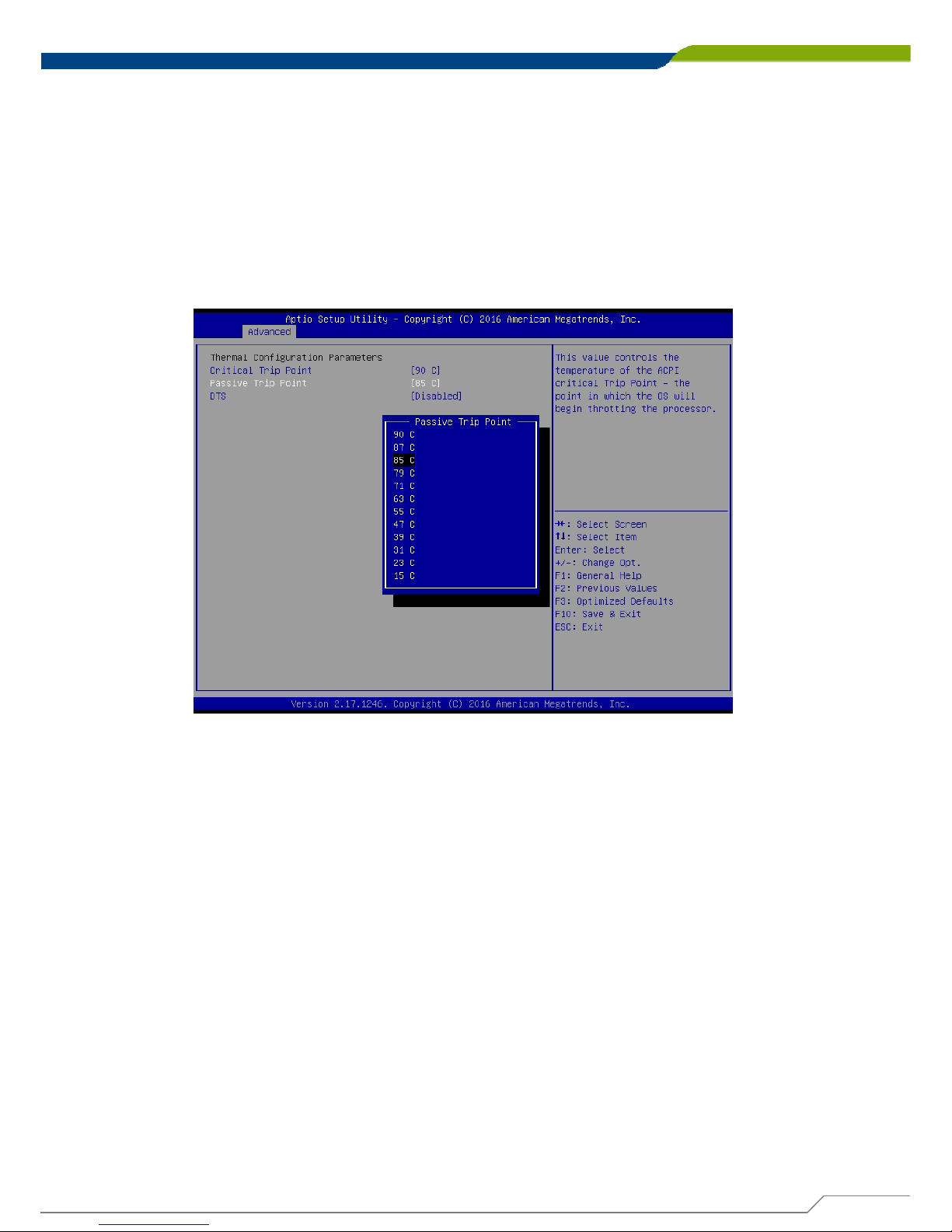
■ Passive Trip Point
This allows 90C, 87C, 85C (default), 79C, 71C, 63C, 55C, 47C, 39C, 31C, 23C, 15C.
■ DTS
Default is Disabled.
Page 63
DA-1000 User’s Manual
63
Chapter 4: BIOS SetupChapter 4: BIOS Setup
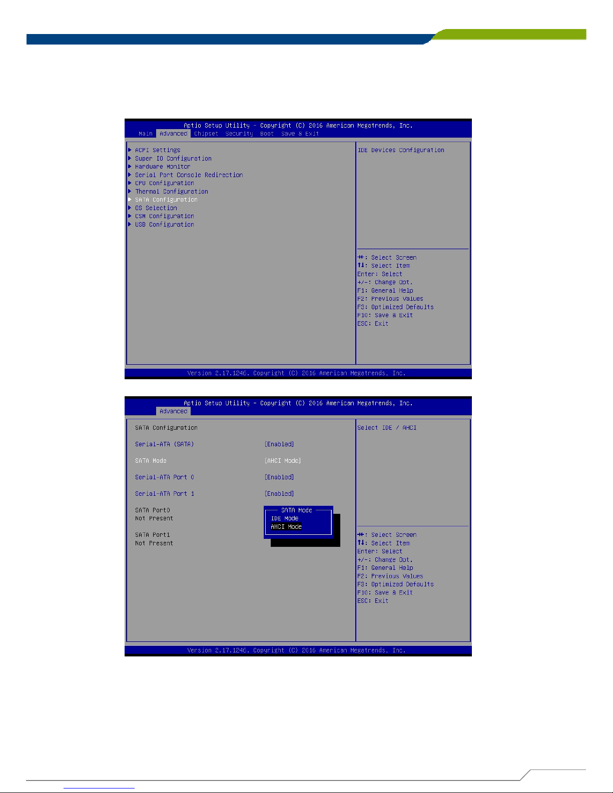
4.3.7 SATA Configuration
This allows you to configure mode of operation and to enable or disable for the
SATA interfaces. Use of default setting is recommended in the section.
■ SATA Mode
This allows to set AHCI mode (default) or IDE mode.
■ Serial-ATA Port 0
Default is Enabled.
■ Serial-ATA Port 1
Default is Enabled.
Page 64
DA-1000 User’s Manual
64
Chapter 4: BIOS SetupChapter 4: BIOS Setup
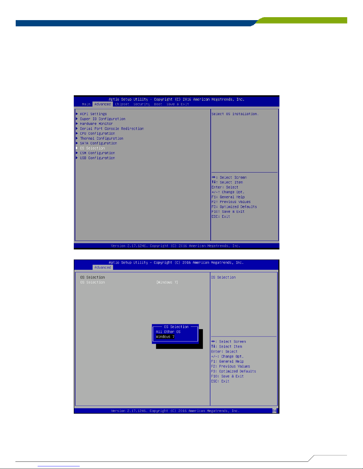
4.3.8 OS Selection
This allows you to configure Windows OS version to install. The purpose of this is
to enable USB 3.0 controller interface. If you set Windows 7 and install the OS,
you will need to install USB 3.0 driver at the OS level to fully support USB 3.0
interfaces. If you set all other OS and install it or later OS, the Windows OS will
easily support USB 3.0 interfaces.
■ OS Selection
This allows to set All Other OS or Windows 7 (default).
Page 65
DA-1000 User’s Manual
65
Chapter 4: BIOS SetupChapter 4: BIOS Setup
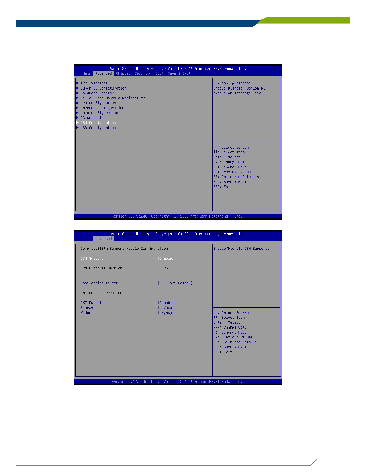
4.3.9 CSM (Compatibility Support Module) Configuration
Following shows default settings.
Page 66

DA-1000 User’s Manual
66
Chapter 4: BIOS SetupChapter 4: BIOS Setup
■ CSM Support
Enables or disables UEFI CSM (Compatibility Support Module) to support a legacy
PC boot process.
■ Boot option filter
Allows user to select which type of operating system to boot.
UEFI and Legacy: Allows booting from operating systems that support legacy option
ROM or UEFI option ROM.
Legacy only: Allows booting from operating systems that only support legacy option
ROM.
UEFI only: Allows booting from operating systems that only support UEFI option
ROM.
This item is configurable only when CSM Support is set to Enabled.
■ PXE Function
This item will allow users to enable or disable PXE function. Default is disabled.
■ Storage
Allows user to select whether to enable the UEFI or legacy option ROM for the
storage device controller.
Do not launch: Disables option ROM.
UEFI: Enables UEFI option ROM only.
Legacy: Enables legacy option ROM only.
■ Video
Allows user to select whether to enable the UEFI or legacy option ROM for the
Video device controller.
Do not launch: Disables option ROM.
UEFI: Enables UEFI option ROM only.
Legacy: Enables legacy option ROM only.
Page 67
DA-1000 User’s Manual
67
Chapter 4: BIOS SetupChapter 4: BIOS Setup
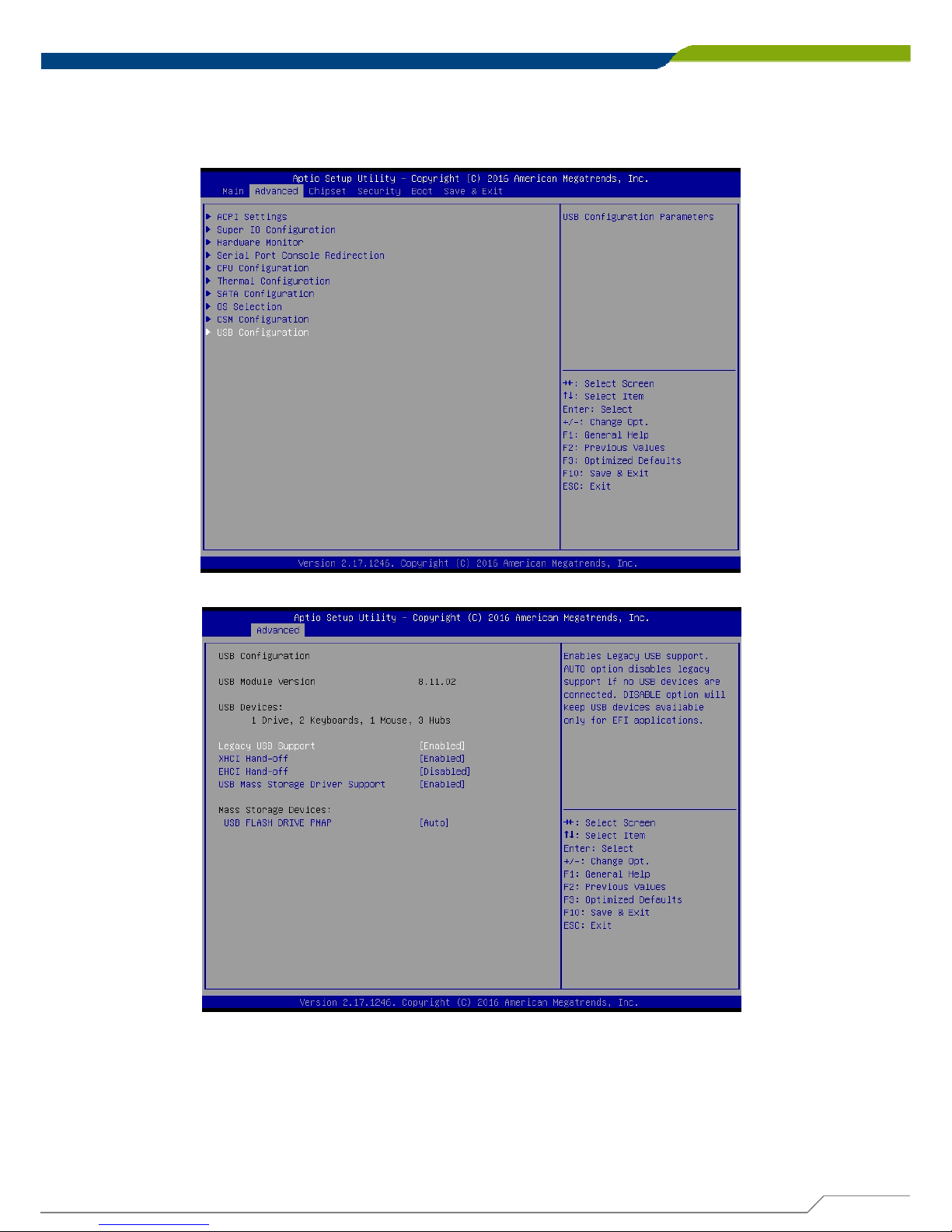
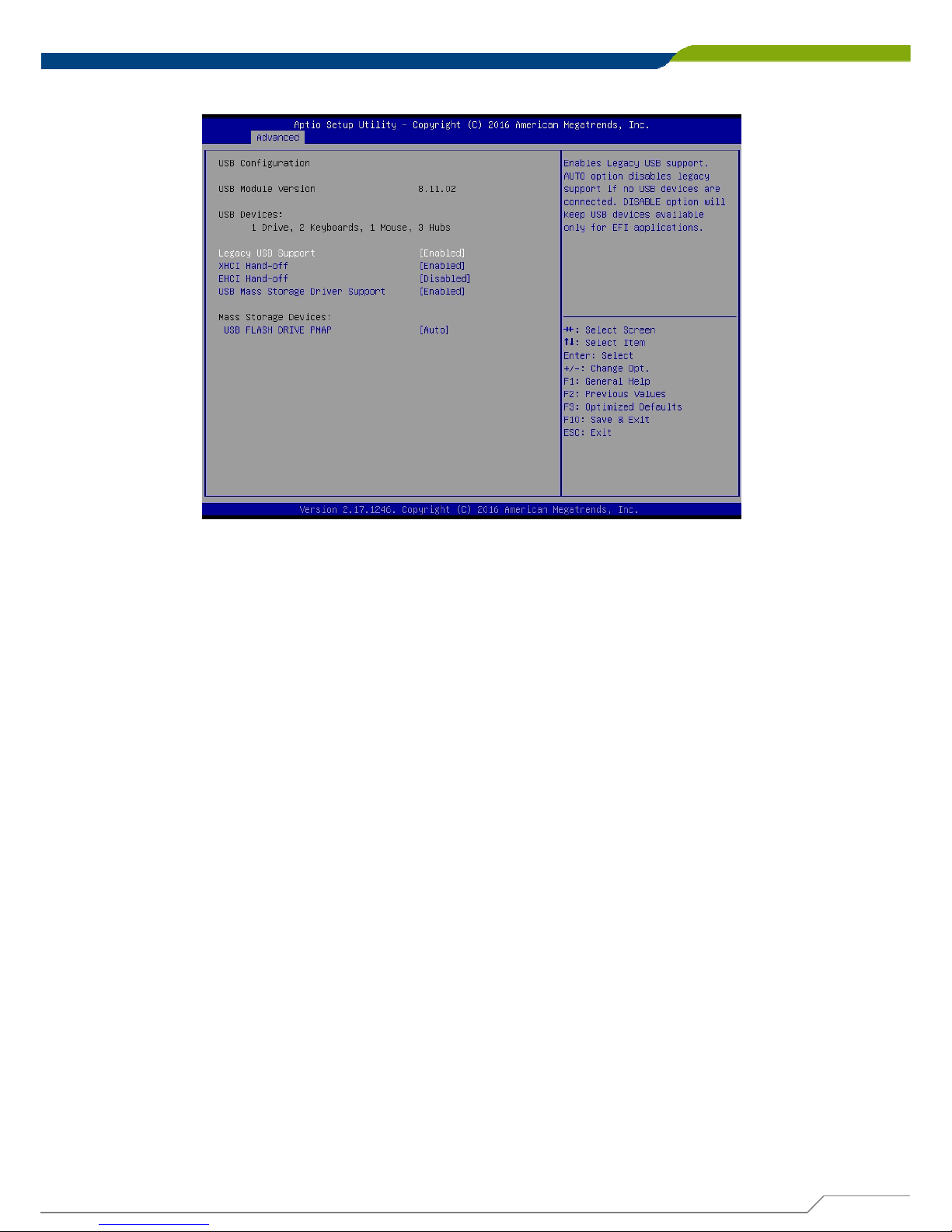
4.3.10 USB Configuration
Following shows default settings.
Page 68
DA-1000 User’s Manual
68
Chapter 4: BIOS SetupChapter 4: BIOS Setup
■ Legacy USB Support
Allows USB keyboard/ mouse to be used in MS-DOS.
■ XHCI Hand-off
Determines whether to enable XHCI (USB3.0) Hand-off feature for an operating
system without XHCI (USB3.0) Hand-off support.
■ EHCI Hand-off
Determines whether to enable EHCI Hand-off feature for an operating system
without EHCI Hand-off support.
■ USB Mass Storage Driver Support
Enables or disables support for USB storage devices.
Page 69
DA-1000 User’s Manual
Chapter 4: BIOS Setup
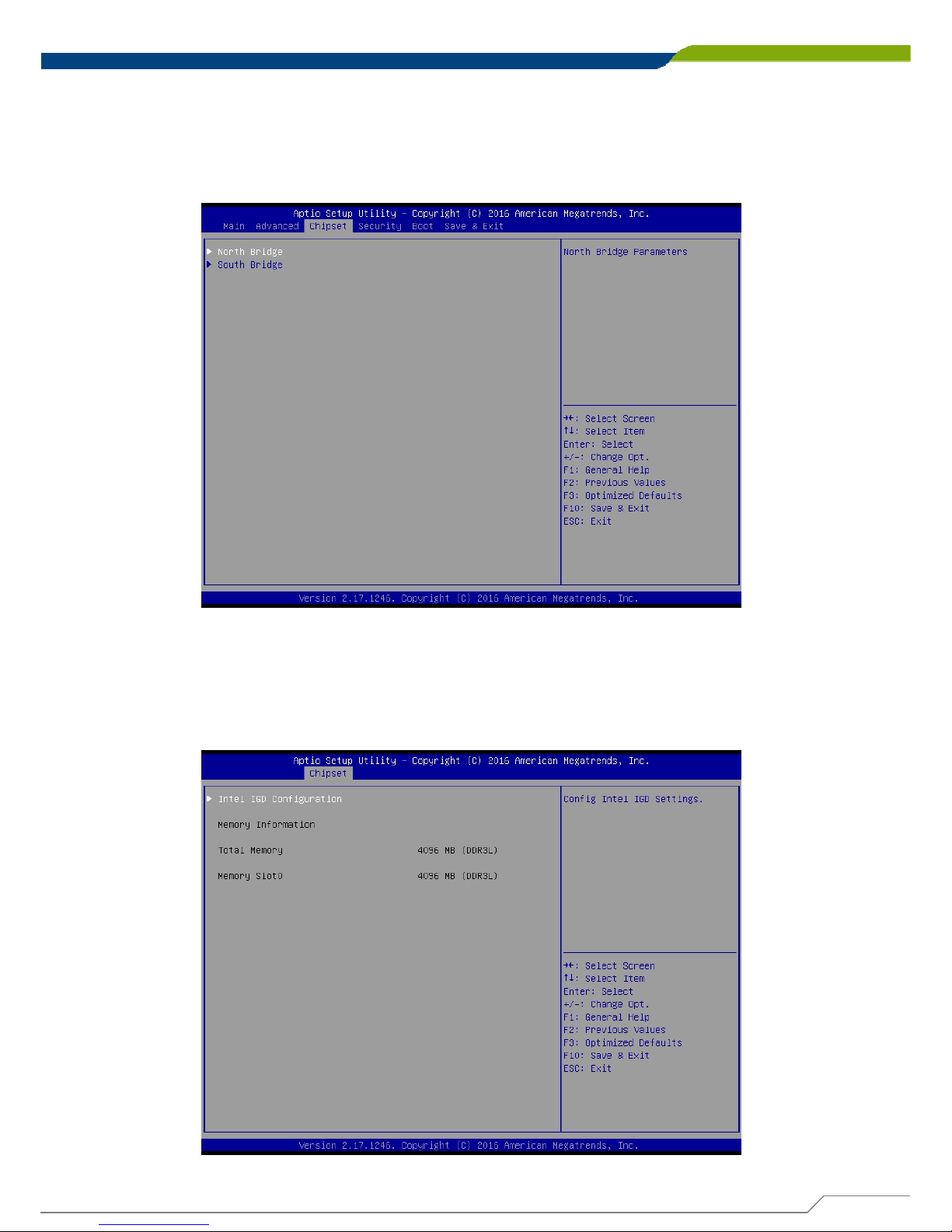
4.4 Chipset
The Advanced menu allows users to set configuration of the CPU and other system
devices. You can select any of the items in the left frame of the screen to go to the sub
menus.
4.4.1 North Bridge
This section provides information on the installed memory size and
memory/onboard graphics-related configuration options.
69
Page 70
DA-1000 User’s Manual
Chapter 4: BIOS Setup
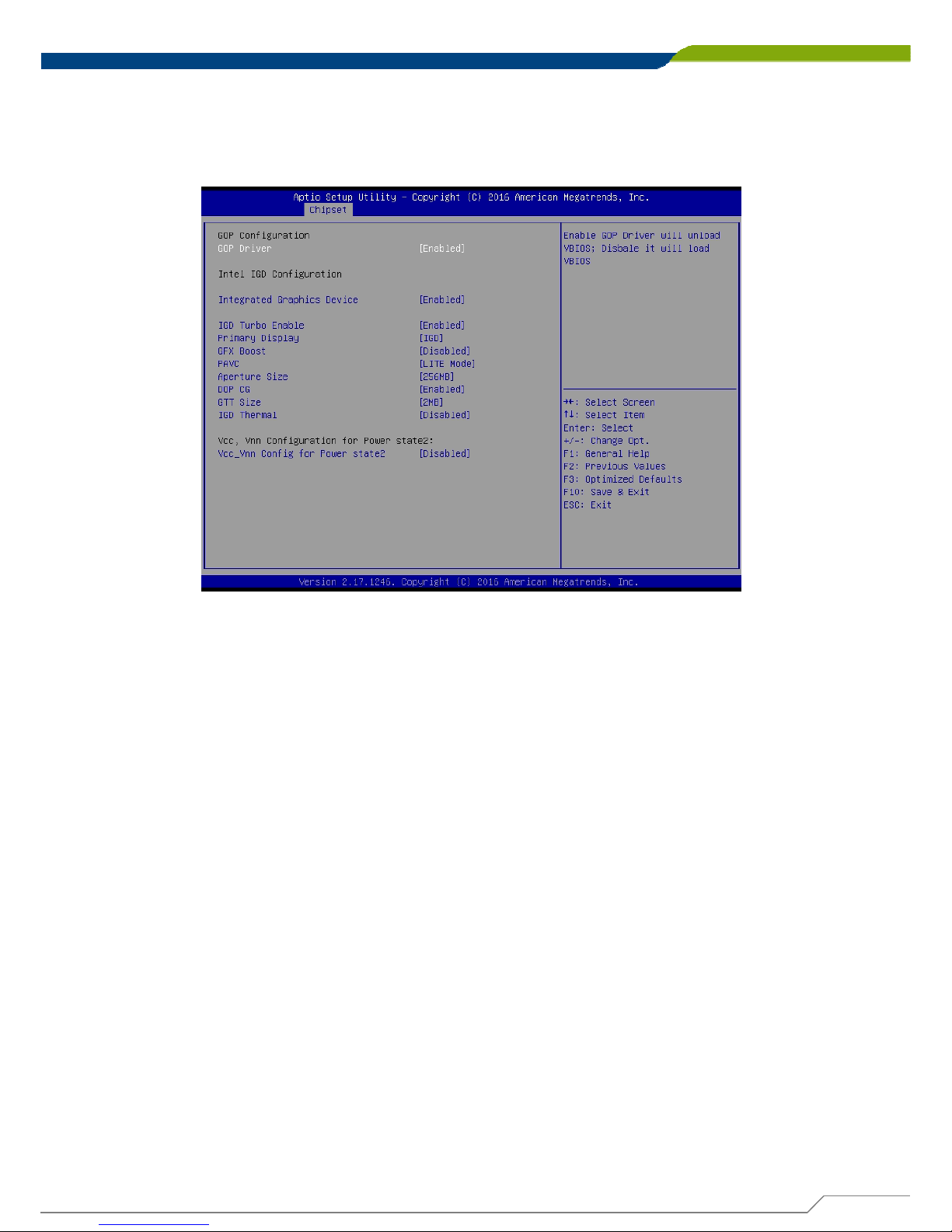
■ Intel IGD Configuration
This section provides onboard graphics-related configuration options. Following is default
setting.
GOP Driver
This item will allow users to enable or disable GOP Driver.
Integrated Graphics Device
This item will allow users to enable or disable Integrated Graphics Device.
IGD Turbo Enable
This item will allow users to enable or disable IGD Turbo.
Primary Display
"Auto or IGFX or PEG or PCIE or SG” optimal to Primary Display.
GFX Boost
This item will allow users to enable or disable GFX Boost.
Aperture Size
Aperture size optimal between 128MB, 256MB, or 512MB.
DOP CG
This item will allow users to enable or disable DOP CG.
GTT Size
GTT size optimal between 1MB or 2MB.
IGD Thermal
This item will allow users to enable or disable IGD Thermal.
70
Page 71
DA-1000 User’s Manual
71
Chapter 4: BIOS SetupChapter 4: BIOS Setup
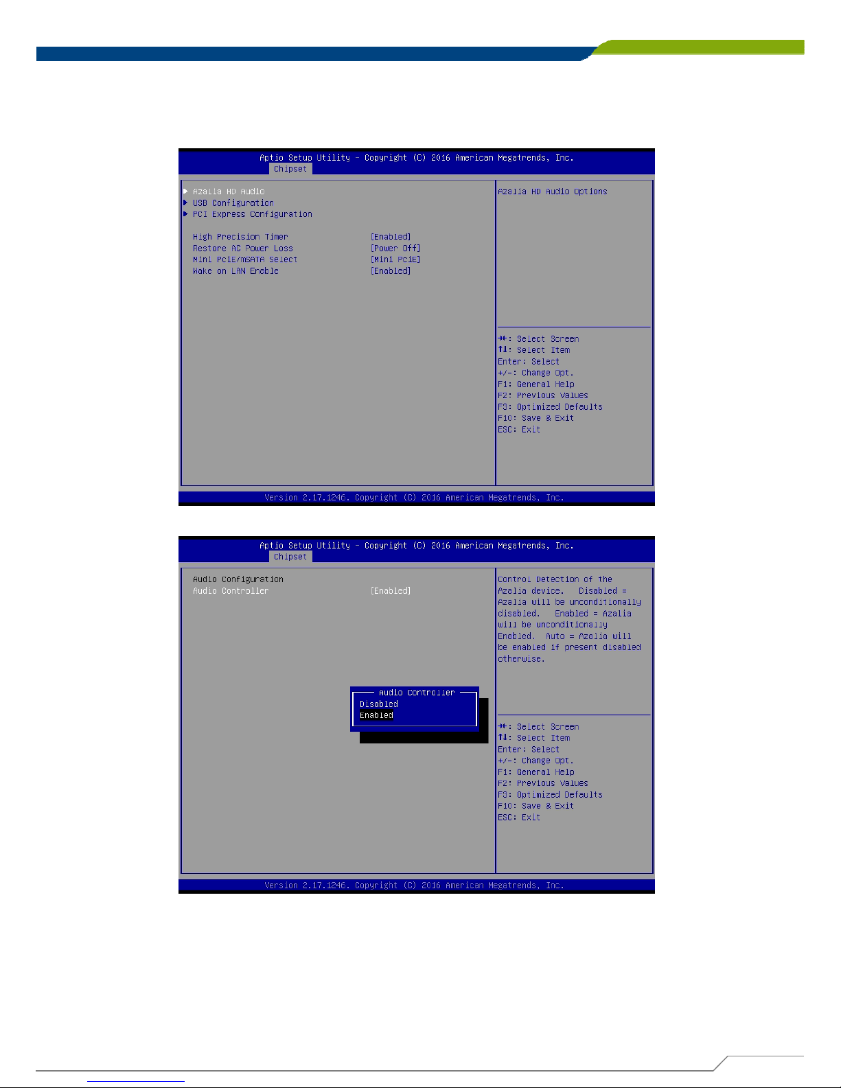
4.4.2 South Bridge
Following shows default settings.
Page 72
DA-1000 User’s Manual
Chapter 4: BIOS Setup
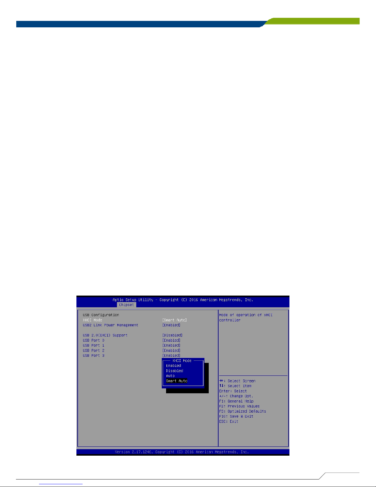
■ USB Configuration
XHCI Mode
This setting disables/enables the USB XHCI controller. The eXtensible Host
Controller Interface (XHCI) is a computer interface specification that defines a
register-level description of a Host Controller for Universal Serial Bus (USB),
which is capable of interfacing to USB 1.0, 2.0, and 3.0 compatible devices. The
specification is also referred to as the USB 3.0 Host Controller specification.
USB 2.0 (EHCI) Support
This setting disables/enables the USB EHCI controller. The Enhanced Host
Controller Interface (EHCI) specification describes the register-level interface for
a Host Controller for the Universal Serial Bus (USB) Revision 2.0.
USB Port 0
This item will allow users to enable or disable USB Port 0.
USB Port 1
This item will allow users to enable or disable USB Port 1.
USB Port 2
This item will allow users to enable or disable USB Port 2.
USB Port 3
This item will allow users to enable or disable USB Port 3.
■ Azalia HD Audio
Control detection of the Azaliadevice.
Audio Controller
Enabled: Azalia will be unconditionally enabled. Default is Enabled.
Disabled: Azalia will be unconditionally disabled.
72
Page 73
DA-1000 User’s Manual
Chapter 4: BIOS Setup
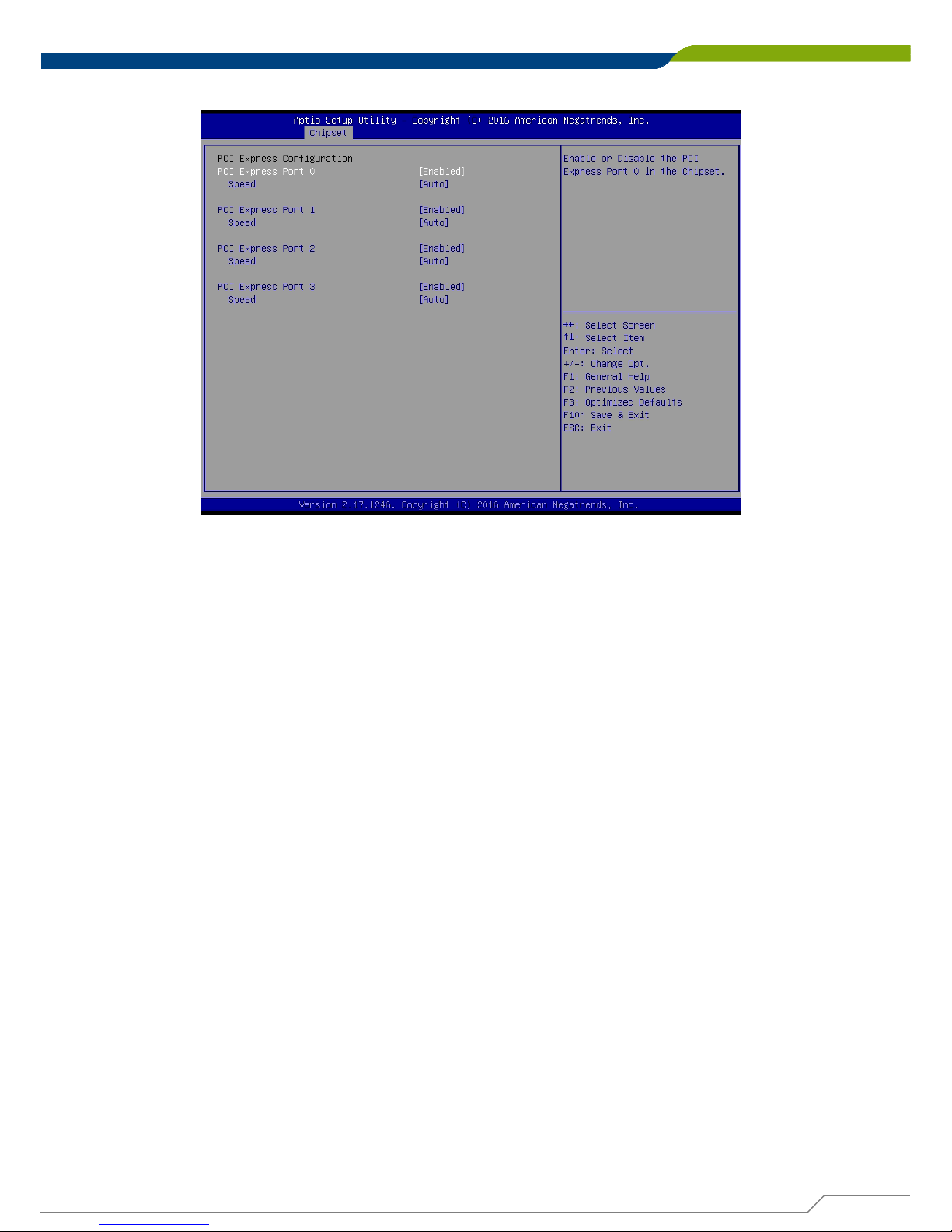
■ PCI Express Configuration
PCI Express Port 0
This item will allow users to enable or disable PCI Express Port 0.
Speed
Change the PCI Express interface speed. Select <AUTO> ,<Gen 2> or <Gen 1>
PCI Express Port 1
This item will allow users to enable or disable PCI Express Port 1.
Speed
Change the PCI Express interface speed. Select <AUTO> ,<Gen 2> or <Gen 1>
PCI Express Port 2
This item will allow users to enable or disable PCI Express Port 2.
Speed
Change the PCI Express interface speed. Select <AUTO> ,<Gen 2> or <Gen 1>
PCI Express Port 3
This item will allow users to enable or disable PCI Express Port 3.
Speed
Change the PCI Express interface speed. Select <AUTO> ,<Gen 2> or <Gen 1>
73
Page 74
DA-1000 User’s Manual
74
Chapter 4: BIOS Setup
4.5 Security
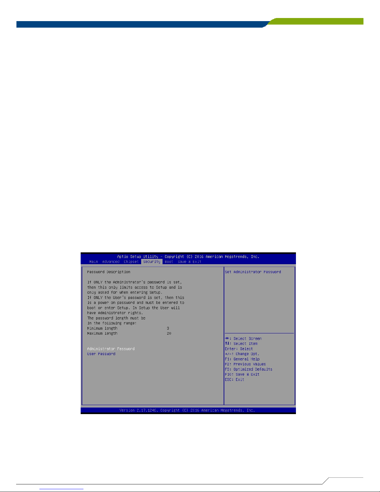
This section allows you to configure and improve your system and allows you to
set up some system features according to your preference.
4.5.1 Administrator Password
Administrator Password controls access to the BIOS Setup utility to edit the content.
4.5.2 User Password
User Password controls access to the system at boot and to the BIOS Setup utility to
only view the content.
■ High Precision Timer
Enable (default) or disable High Precision Event Timer (HPET) in the operating
system.
■ Restore AC Power Loss
This setting specifies whether your system will reboot after a power failure or
interrupt occurs. Available settings are:
Power Off: Leave the computer in the power off state. This is the default setting.
Power On: Leave the computer in the power on state.
Last State: Restore the system to the previous status before power failure or
interrupt occurred.
■ Mini PCIe/mSATA Select
This allows to set shared Mini PCIe slot for use as either Mini PCIe (default) or
mSATA interface.
■ Wake on LAN Enable
This enables or disables Wake on LAN feature. Default is Enabled.
Page 75
DA-1000 User’s Manual
75
Chapter 4: BIOS Setup
4.6 Boot
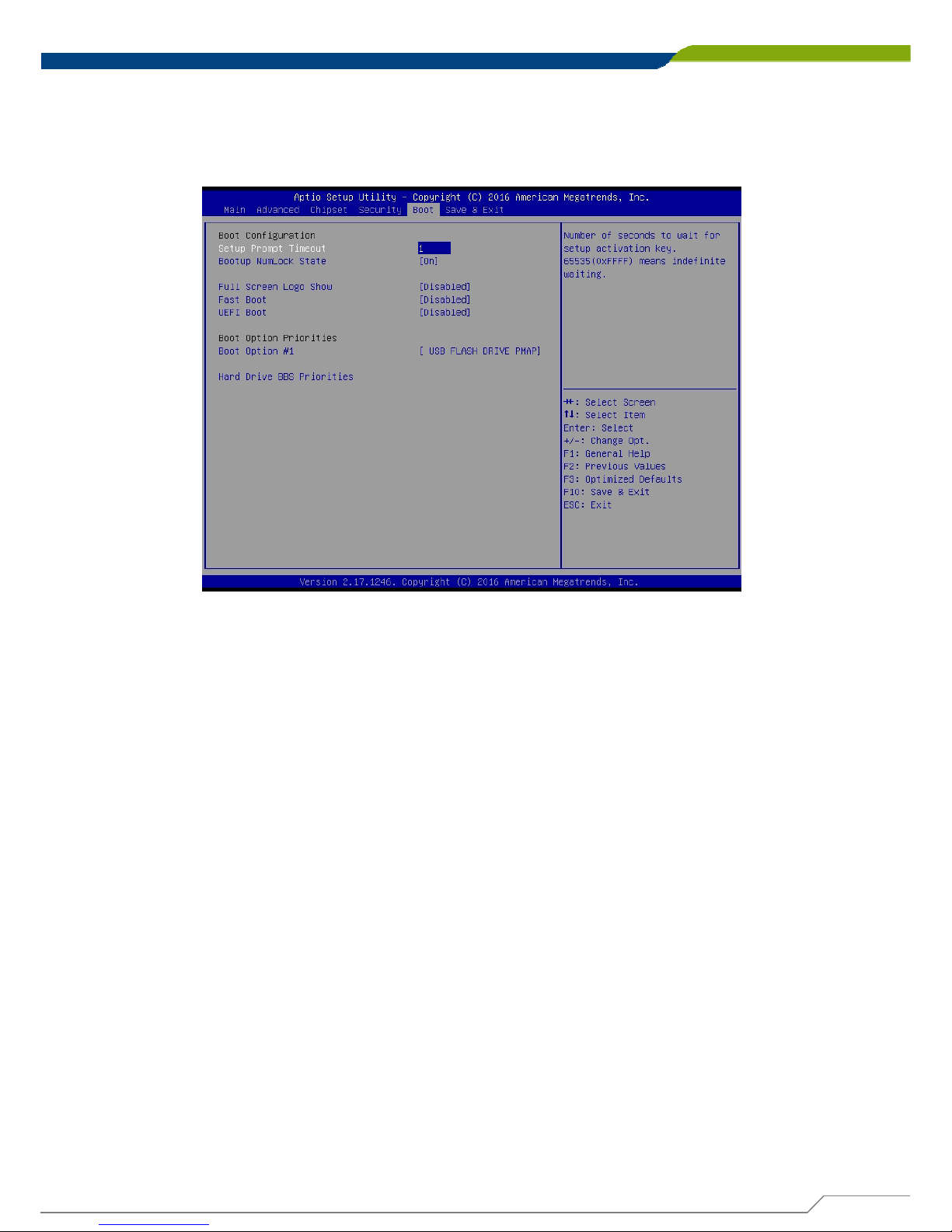
This section allows you to configure the boot settings. Following is the default
settings.
4.6.1 Setup Prompt Timeout
Use this item to set number of seconds to wait for setup activation key.
4.6.2 Bootup NumLock State
Select the Power-on state for NumLock key.
4.6.3 Full Screen Logo Show
This item allows user to enable or disable full screen logo show.
4.6.4 Fast Boot
This item allows user to enable or disable Fast Boot option.
4.6.5 UEFI Boot
This allows to boot device with UEFI-based (not legacy) OS.
Page 76
DA-1000 User’s Manual
76
Chapter 4: BIOS Setup
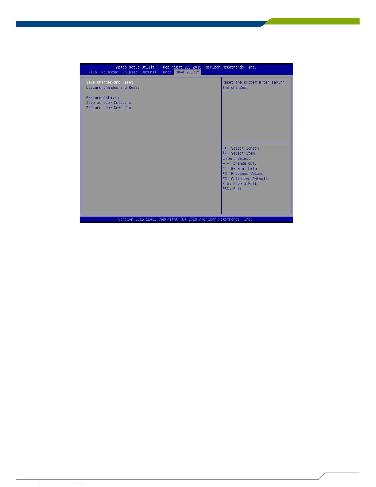
4.7 Save & Exit
This section allows you to configure the boot settings.
4.7.1 Save Changes and Reset
This item allows user to reset system setup after saving changes.
4.7.2 Discard Changes and Reset
This item allows user to reset system setup without saving any changes.
4.7.3 Restore Defaults
This item allows user to restore/ load default values for all the options.
4.7.4 Save as User Defaults
This item allows user to save the changes done so far as user defaults.
4.7.5 Restore User Defaults
This item allows user to restore the user defaults to all the options.
Page 77

Product Application
(For CMI-DIO100 Only)
Chapter 5
Page 78
DA-1000 User’s Manual
78
5.1 Digital I/O (DIO) application
This section describes DIO application of the product. The content and
application development are better understood and implemented by well
experienced professionals or developers.
Chapter 5: Product application
5.1.1 Digital I/O Programming Guide
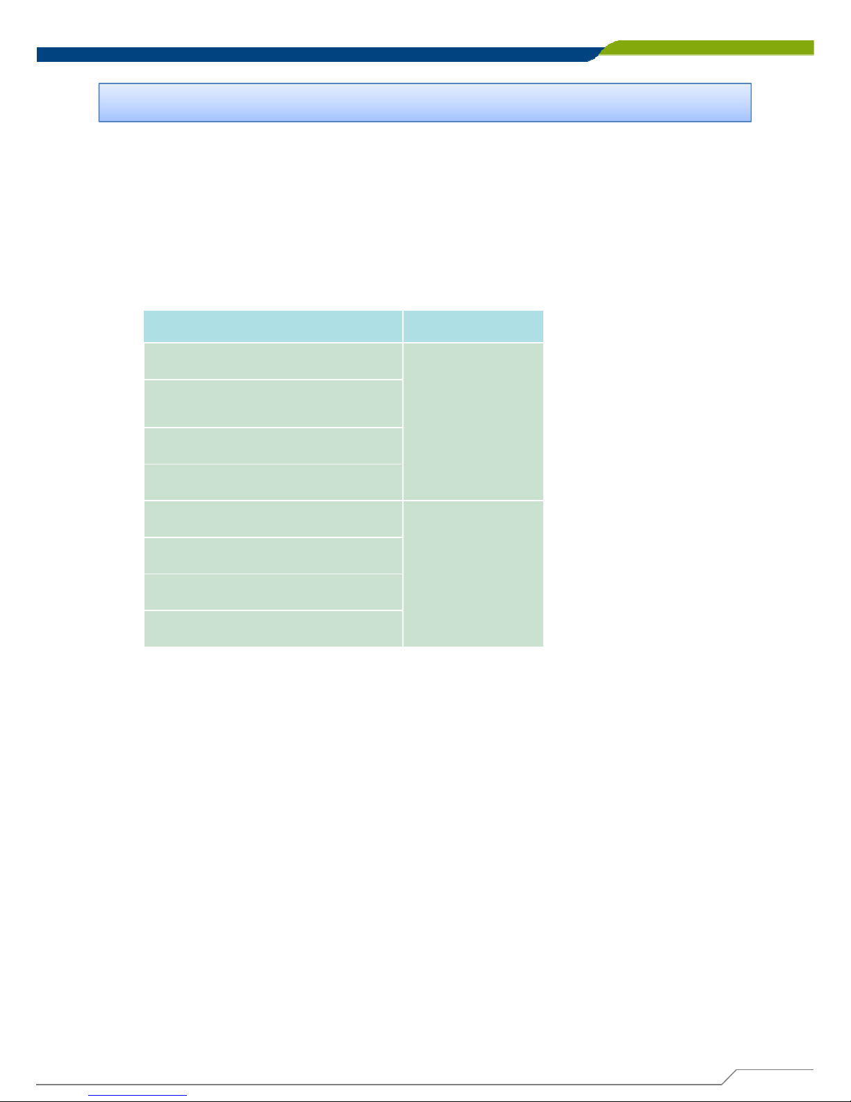
5.1.1.1 Pins for Digital I/O for Cincoze DA series product
Item Standard
GPIO54 (Pin13)
DI
GPIO55 (Pin14)
GPIO56 (Pin15)
GPIO57 (Pin16)
GPIO60 (Pin17)
DO
GPIO61 (Pin18)
GPIO62 (Pin19)
GPIO63 (Pin20)
5.1.1.2 Programming Guide
To program the Super I/O chip F81866A configuration registers, the following
configuration procedures must be followed in sequence:
(1) Enter the Extended Function Mode
(2) Configure the configuration registers
(3) Exit the Extended Function Mode
The configuration register is used to control the behavior of the corresponding
devices. To configure the register, use the index port to select the index and then
write data port to alter the parameters. The default index port and data port are 0x4E
and 0x4F respectively. Pull down the SOUT1 pin to change the default value to
0x2E/ 0x2F. To enable configuration, the entry key 0x87 must be written to the
index port. To disable configuration, write exit entry key 0xAA to the index
port. Following is an example to enable configuration and to disable configuration by
using debug.
-o 4e 87
-o 4e 87 (enable configuration)
-o 4e aa (disable configuration)
This chapter descripts the DIO applications.
Page 79
DA-1000 User’s Manual
79
Chapter 5: Product application
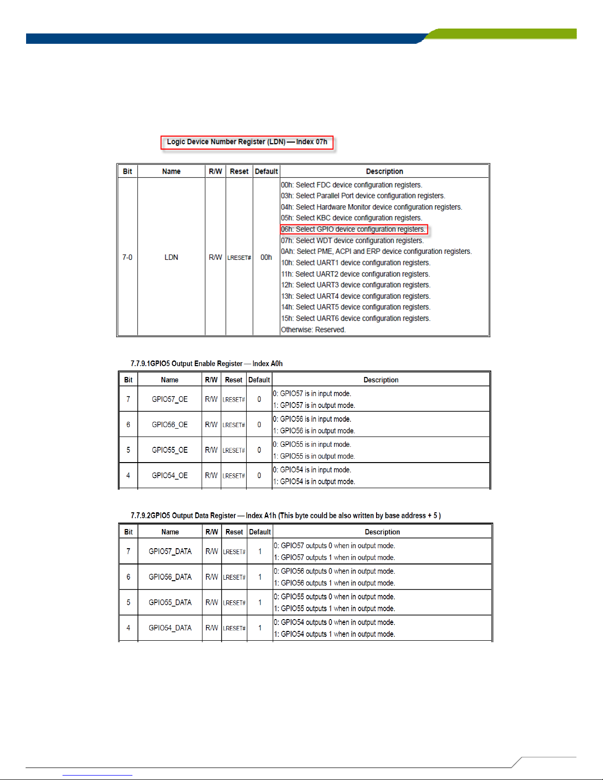
5.1.1.3 Relative Registers
To program the F81866A configuration registers, the following configuration
procedures.
Page 80
DA-1000 User’s Manual
80
Chapter 5: Product application
5.1.1.4 Sample Code in C Language
5.1.1.4 .1 Control of GP54 to GP57
#define AddrPort 0x4E
#define DataPort 0x4F
<Enter the Extended Function Mode>
WriteByte(AddrPort, 0x87)
WriteByte(AddrPort, 0x87) // Must write twice to enter Extended mode
<Select Logic Device>
WriteByte(AddrPort, 0x07)
WriteByte(dataPort, 0x06)
//Select logic device 06h
<Output/Input Mode Selection> // Set GP54 to GP57 input Mode
WriteByte(AddrPort, 0xA0) // Select configuration register A0h
WriteByte(DataPort, (ReadByte(DataPort) ǀ 0x0X))
// Set (bit 4~7) = 0 to select GP 54~57 as Input mode.
<Input Value>
WriteByte(AddrPort, 0xA1) // Select configuration register A1h
ReadByte(DataPort, Value) // Read bit 4~7 (0xFx)= GP54 ~57
as High.
<Leave the Extended Function Mode>
WriteByte(AddrPort, 0xAA)
Page 81

DA-1000 User’s Manual
81
Chapter 5: Product application
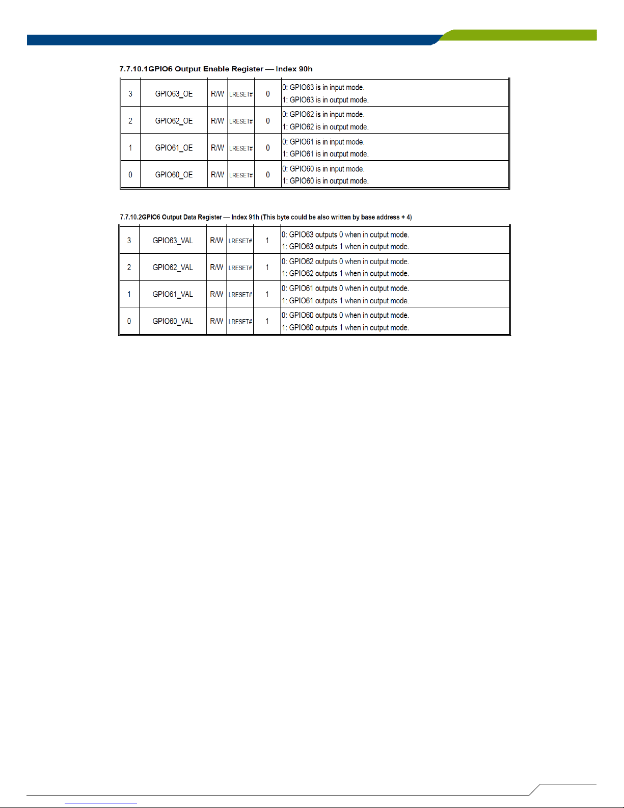
5.1.1.4 .2 Control of GP60 to GP63
#define AddrPort 0x4E
#define DataPort 0x4F
<Enter the Extended Function Mode>
WriteByte(AddrPort, 0x87)
WriteByte(AddrPort, 0x87) // Must write twice to enter Extended mode
<Select Logic Device>
WriteByte(AddrPort, 0x07)
WriteByte(DataPort, 0x06)
// Select logic device 06h
<Output/Input Mode Selection> // Set GP60 to GP63 output Mode
WriteByte(AddrPort, 0x90) // Select configuration register 90h
WriteByte(DataPort, (ReadByte(DataPort) & 0xXF))
// Set (bit 0~3) = 1 to select GP 60 ~63 as Output mode.
<Output Value>
WriteByte(AddrPort, 0x91) // Select configuration register 91h
WriteByte(DataPort, Value) // Set bit 0~3=(0/1) to output GP 60~63
as Low or High
<Leave the Extended Function Mode>
WriteByte(AddrPort, 0xAA)
Page 82
DA-1000 User’s Manual
82
Chapter 5: Product application
5.1.1.5 Change base address
<Enter the Extended Function Mode>
WriteByte(AddrPort, 0x87)
WriteByte(AddrPort, 0x87) // Must write twice to enter Extended mode
<Select Logic Device>
WriteByte(AddrPort, 0x07)
WriteByte(dataPort, 0x06)
// Select logic device 06h
WriteByte(AddrPort, 0x60) // Select configuration register 60h
WriteByte(DataPort, (ReadByte(DataPort) ǀ 0x03))
WriteByte(AddrPort, 0x61) // Select configuration register 61h
WriteByte(DataPort, (ReadByte(DataPort) ǀ 0x20))
<Leave the Extended Function Mode>
WriteByte(AddrPort, 0xAA)
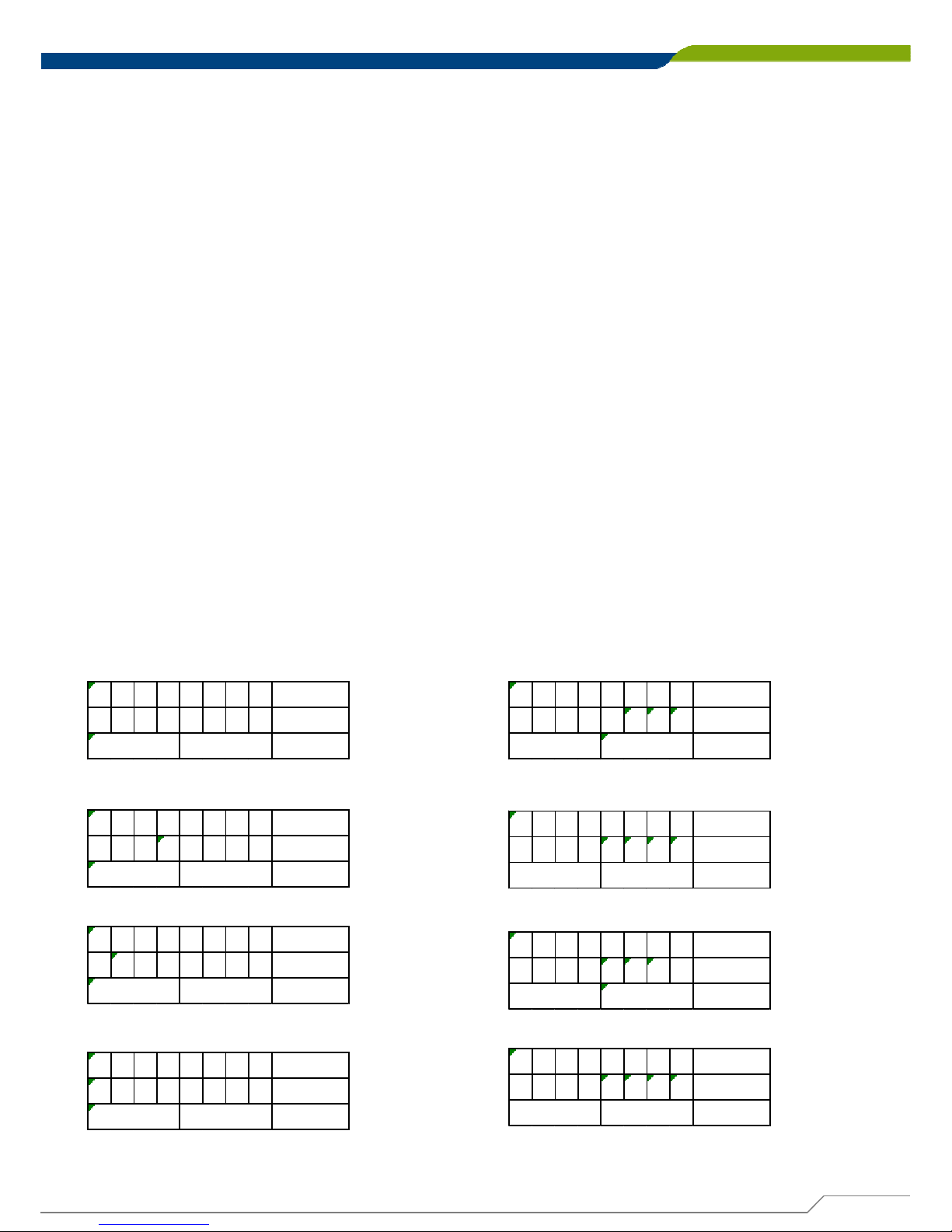
GPIO Port base address 0x0320/h
5.1.1.6 DATA Bit Table (DIO)
= DI1
76543210 bit
0001---- value
/h
1X
= DI2
76543210 bit
0010---- value
/h
2X
= DI3
76543210 bit
0100---- value
/h
4X
= DI4
76543210 bit
1000---- value
/h
8X
= DO1
76543210 bit
----0001 value
/hX
1
= DO2
76543210 bit
----0010 value
/hX2
= DO3
76543210 bit
----0100 value
/hX
4
= DO4
76543210 bit
----1000 value
/hX8
Page 83

DA-1000 User’s Manual
83
Chapter 5: Product application
5.1.1.7 DIO I/O Port Address
DI4 DI3 DI2 DI1 DO4 DO3 DO2 DO1 Pin Definition
76543210 Data Bits
DI DO DIO
0xA05 0xA03 I/O Port address
• 4x Digital Input (Source Type)
• Input Voltage (Dry Contact)
- Logic 0: Close to GND
- Logic 1: Open
• Input Voltage:
- Logic 0: -3V (Min/D1 to COM+)
• 4x Digital Output
- Supply Voltage: 5~48V
- Sink Current: 1A (Max)
- DIO Max: 48V
5.2 Digital I/O (DIO) Hardware Specification
Page 84

DA-1000 User’s Manual
84
© 2014 Cincoze Co., Ltd. All rights reserved.
The Cincoze logo is a registered trademark of Cincoze Co., Ltd.
All other logos appearing in this catalog are the intellectual property of the respective company, product, or
organization associated with the logo.
All product specifications and information are subject without notice.
www.cincoze.com
 Loading...