

Page 1

Netkom XT65
User Guide
wireless modules by
Copyright © Netkom Sp. z o.o. All rights reserved
Cinterion
embedded
Page 2

Page 3

Safety information
Radio devices have limitations in the
vicinity of electronic devices:
When in hospitals or other health care •
facilities, observe the restrictions on the
use of mobiles. Switch off the cellular
terminal or mobile if to be instructed
to do so by the guidelines posted in
sensitive areas. Medical equipment may
be sensitive to RF energy.
Switch the Terminal off when flying.•
Secure it so that it cannot be switched
on inadvertently.
Do not operate the cellular terminal or •
mobile in the presence of flammable
gases or fumes. Operation of any
electrical equipment in potentially
explosive atmospheres can constitute a
safety hazard.
Interference can occur if the device is •
used near televisions, radios or PCs.
In order to avoid possible damage, •
we recommend that you only use the
specified accessories. These have been
tested and shown to work well with the
Terminal. However, the warranty does
not cover these accessories.
The warranty does not apply in the
event of improper use.
Copyright © Netkom Sp. z o.o. All rights reserved
3
Page 4

Contents
Safety information ..............................................3
Contents ................................................................4
Front view ..................................................6
Rear view ................................................... 6
Overview ...............................................................6
Product description ............................................7
Highlights ................................................... 8
Applications ............................................... 8
Interfaces ................................................... 8
Highlights ................................................... 9
SMS ........................................................... 9
Certification ................................................9
Features ................................................................9
Data ......................................................... 10
Fax ............................................................ 10
Supplementary services .......................... 10
External interfaces ................................... 10
Accessories .............................................. 10
Package contents / scope of delivery .......11
Safety and installation information ..........11
Installation ..........................................................11
DIN rail installation .................................. 12
IO interface .............................................. 13
Interface description .......................................13
IO Interface Connector ............................. 14
Power supply ............................................ 17
Programmable outputs ............................ 18
Inputs ....................................................... 19
Analog input ............................................. 20
Serial interface ......................................... 22
4
Copyright © Netkom Sp. z o.o. All rights reserved
Page 5

Contents
I2C interface ............................................. 24
1-Wire interface ....................................... 26
VDD supply .............................................. 27
Reset and watchdog ............................... 28
Watchdog ................................................29
GSM antenna connector FME ................. 35
GPS antenna connector SMA .................. 37
GSM status LED ...................................... 39
Programmable LED ..................................41
Hardware settings ................................... 42
Switching on/off terminal ........................ 44
Startup ................................................................44
AT command control ................................ 45
SW update ............................................... 45
Firmware .............................................................45
Maintenance tips ..................................... 46
Certification .............................................. 46
Certification / maintenance............................46
Copyright © Netkom Sp. z o.o. All rights reserved
5
Page 6

SIM card
reader
18-PIN
connector
Antenna
connectors
LEDs display
Reset
Front view
Rear view
Overview
6
Copyright © Netkom Sp. z o.o. All rights reserved
Page 7

Product description
The heart of this modern
compact modem is a Java™
programmable GSM and GPS modem. It
will send current state and GPS position
of the logistic unit via SMS or GPRS.
An integration in a VPN network is
possible too. The competed price of GPRS
data transfer with known quality gives
users advantage to be always connected.
Why Netkom XT65?
This device is a build for join
between the GPS technology and the
logistic management.
The Netkom XT65 gives an ideal solution
for transporting and logistic company.
The XT65 it’s an excellent
ingredient which joins the feature of
Java and the german excellence of
Cinterion(Siemens).
Copyright © Netkom Sp. z o.o. All rights reserved
7
Page 8

Product description
Highlights
Applications
Interfaces
Quad-band GSM 850/900/1800/1900•
GPRS multi-slot class 12•
Output Power: Class4 / Class 1•
SIM via GSM or GPRS•
SIM application tool kit•
JAVA included•
Logistic monitoring•
Remote monitoring•
Remote meter reading•
GSM antenna: SMA/FME connector•
GPS antenna: SMA connector•
Reset button•
4-pole Western plug (female) for audio •
accessory
18 pin Micro-N-Lok connector: •
- 1 x analog in (ADC) with selectable
(GPIO) range
- Vout (3V)
- 4 x digital inputs Vin<30V
(3 x active high, 1 x active low)
- 2 x output OC
- 1 x RS232 serial interface
(RXD, TXD,RTS,CTS )
- I2C interface
- 1-wire interface
- Power supply
SIM card interface 3V, 1.8V•
Operating status LED: •
- for GSM/ GPRS
Control LED(programmable)•
Micro-switch for select peripheral •
devices (only for advanced users)
8
Copyright © Netkom Sp. z o.o. All rights reserved
Page 9

Features
Highlights
SMS
Quad-band 850/900/1800/1900 MHz•
CE certificate•
JAVA included•
Dimensions(WxDxH): 76x55x30•
Weight: 143•
Ambient temperature range: -25•
SMS cell broadcast•
Text and PDU mode•
Transmission of SMS alternatively over •
CSD or GPRS
Copyright © Netkom Sp. z o.o. All rights reserved
9
Page 10

Features
Data
Fax
Supplementary
services
External interfaces
Accessories
GPRS: max. 86 kbps DL & UL•
Coding scheme CS 1, 2, 3, 4•
PBCCH support•
CSD up to 14.4 kbps•
USSD support•
Non-transparent mode•
V.11 0•
Group 3, class 1•
Phone book•
Multiparty•
18-pin Mocro-N-Lok connector•
SIM card holder•
GPS antenna connector SMA•
GSM antenna connector FME•
Antenna GSM, Antenna GPS, SIM cards
10
Copyright © Netkom Sp. z o.o. All rights reserved
Page 11

Installation
Package contents /
scope of delivery
Safety and
installation
information
Netkom XT65 terminal
Package unit:
Netkom XT65 terminal•
Optional accesories*:
Antenna•
GPS GSM -
*In order to avoid possible damage, we recommend that you
only use the specified and proven accessories.
Connect a fast 1.25 A fuse to the •
incoming line for the positive supply
voltage to protect the modem.
If a power supply unit is used to supply •
the modem, it must meet the demands
placed on SELV circuits in accordance
with EN60950. When using batteries
and accumulators, adhere to the
relevant regulations.
The maximum permissible connection •
length between the modem and the
supply source is 3 m.
Your supplier will be pleased to •
provide you with a detailed technical
description and technical support for
the Cinterion modem.
Copyright © Netkom Sp. z o.o. All rights reserved
11
Page 12

Installation
DIN rail
installation
The terminal can be mounted on DIN rail
with optional clips.
12
Copyright © Netkom Sp. z o.o. All rights reserved
Page 13

Interface description
IO interface
The following interfaces are available on
the modem:
18-pin Micro-N-Lok connector•
SIM card holder•
GSM antenna connector FME•
GPS antenna connector SMA•
Copyright © Netkom Sp. z o.o. All rights reserved
Via the IO interface connector the
following interfaces and functions are
provided:
•Programmableoutputs
•Inputs
•Oneanaloginput
•Serialinterface(ASC0)
•Powersupply
13
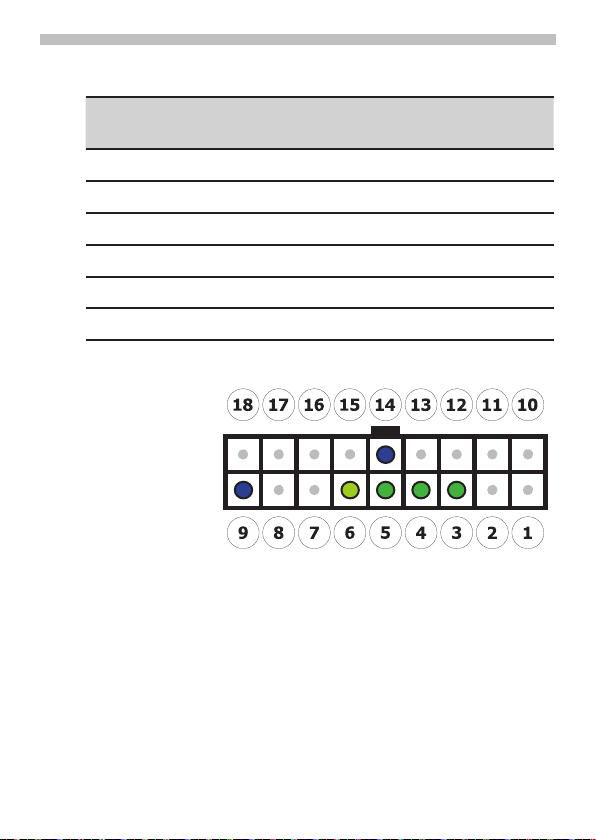
Page 14

Interface description
IO Interface
Connector
This chapter provides specifications for
the 18-pin IO interface connector which
serves the outputs, inputs and power
supply interfaces of the Terminal. The
type of the receptacle assembled on the
Netkom XT65 terminal is Micro Mate-NLOK 3mm from Tyco Electronics. Mating
headers can be chosen from the Tyco
Micro Mate-N-LOK Series. For latest
product information please contact your
Micro Electronics dealer or visit the Tyco
home page, for example:
http://www.tycoelectronics.com
Tyco Micro Mate-N-LOK series on the
Netkom XT65 Terminal
14
Copyright © Netkom Sp. z o.o. All rights reserved
Page 15

Receptacle contact for Tyco Micro
Mate-N-LOK series
Interface description
Mating connector Tyco Micro MateNLOK series
Copyright © Netkom Sp. z o.o. All rights reserved
15
Page 16

Interface description
Parameter Specification
Number of contacts 18
Voltage rating 250V 250V
Current rating 5A max. 5A max
Resistance 0.02 Ohm max. per contact
Dielectric withstanding
voltage
Operating temperature - 40°C ... +105°C
Contact centerline 3.0mm
Mating force 6.67N max. per contact
Receptacle housing material Flame-retardant black
Contact material Phosphor bronze
1500VAC
thermoplastic
16
Copyright © Netkom Sp. z o.o. All rights reserved
Page 17

Pin number Function
9 GND
18 POWER
Interface description
Power supply
The power supply of the Netkom XT65
Terminal has to be a single voltage
source of POWER = 8V…30V capable
of providing a peak during an active
transmission. The uplink burst causes
strong ripples (drop) on the power lines.
The Netkom XT65 terminal is protected
from supply voltage reversal and
overvoltage.
A fast acting fuse I≥0.8A with melting
integral I²t (0.8 … 1.5 A²s) is necessary to
use the Netkom XT65 Terminal at a 24V
power supply system for vehicles.
The power supply must be compliant with
the EN60950 guidelines.
Locations of power supply pins
Copyright © Netkom Sp. z o.o. All rights reserved
17
Page 18

Interface description
Pin
number
Function GPIO
1 OUT1 GPIO8
2 OUT2 GPIN5
9 GND
14 GND*
*recommended
Programmable
outputs
The terminal has two programmable type
OC outputs.
Attention!
High GPIO level is equal low level on the
terminal’s output and the same way back.
Locations of programmable outputs
pins
18
Copyright © Netkom Sp. z o.o. All rights reserved
Page 19
Interface description
Pin
number
Function GPIO Active level
3 IN1 GPIO 6
LOW
4 IN2 GPIO 7
HIGH
5 IN3 GPIO 9
HIGH
6 IN4 GPIO 10
HIGH
9 GND
14 GND*
*recommended
The terminal has four inputs.
Inputs
Locations of inputs pins
Copyright © Netkom Sp. z o.o. All rights reserved
19
Page 20

Interface description
Pin
number
Function GPIO
7 ADC ADC1
9 GND
14 GND
*recommended
Analog input
Location of analog input pins
Second analog input (ADC2) is internally
connected to power supply.
20
Copyright © Netkom Sp. z o.o. All rights reserved
Page 21

Interface description
GPIO 2GPIO 3Vmin
[V]
Vmax
[V]
0 0
0
6
1 0
0
12
0 1
0
18
1 1 0 24
Power supply measurement range is
8-28V
You can program a wide of the
measurement.
Copyright © Netkom Sp. z o.o. All rights reserved
21
Page 22

Interface description
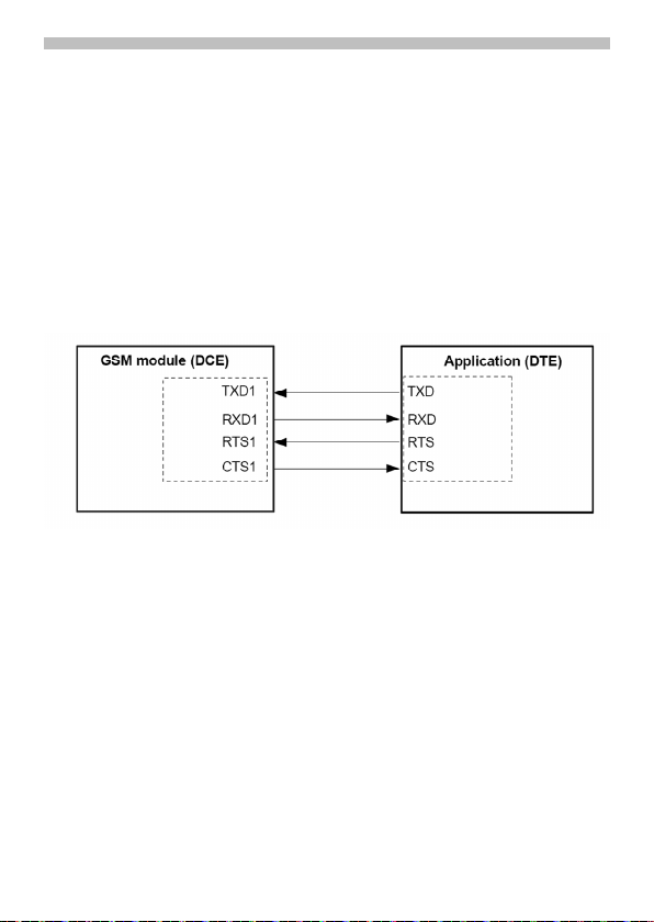
Serial interface
The serial interface of the Netkom
XT65 terminal is intended for the
communication between the GSM module
and the host application. This RS-232
interface is a data and control interface
for transmitting data, AT commands and
providing multiplexed channels. EMC
immunity complies with
the vehicular environment requirements
according to EN 301 489-7.
Location of serial interface pins
Netkom XT65 Terminal is designed for use
as a DCE. Based on the conventions for
DCE-DTE connections it communicates
with the customer application (DTE) using
the following signals:
•PortTXDatapplicationsendsdatato
TXD of Netkom XT65.
•PortRxDatapplicationreceivesdata
from RXD of Netkom XT65.
22
Copyright © Netkom Sp. z o.o. All rights reserved
Page 23
Interface description
The RS-232 interface is implemented as
a serial asynchronous transmitter and
receiver conforming to ITU-T V.24 Interchange Circuits DCE. It is configured for
8 data bits, no parity and 1 stop bit and
can be operated at fixed bit rates from
300bps to 460,800bps. Autobauding supports bit rates from 1,2bps to 460,800bps.
Hardware handshake using the /RTS and /
CTS signals and XON/XOFF software flow
control are supported.
Copyright © Netkom Sp. z o.o. All rights reserved
23
Page 24

Interface description
Pin number Function
15 I2CDAT
16 I2CCLK
17 +3V
9 GND*
14 GND
*recommended
I2C interface
The I²C interface is located at the IO
interface connector of the Netkom XT65
Terminal. I²C is a serial, 8-bit oriented data
transfer bus for bit rates up to 400kbps in
fast mode. It consists of two lines. These
are the serial data line I2CDAT and the
serial clock line I2CCLK.
The Netkom XT65 Terminal acts as a single
master device, e.g. the clock I2CCLK is
driven by the Terminal. The connection
I2CDAT is a bi-directional line.
24
Copyright © Netkom Sp. z o.o. All rights reserved
Page 25

Interface description
Each device which is connected to
the bus is software addressable by a
unique address and simple master/
slave relationships exists at all times. The
Terminal operates as master-transmitter
or as master-receiver. The customer
application transmits or receives data only
on request of the Terminal. To configure
and activate the I2C interface use the
AT^SSPI command.
Location of I2C interface pins
Below addresses are reserved for
watchdog, I2C and 1wire bridge:
• 0x02,0x01
• 0x30,0x31
Copyright © Netkom Sp. z o.o. All rights reserved
25
Page 26

Interface description
Pin number Function
8 1-wire
9 GND*
14 GND
*recommended
1-Wire interface
1-Wire® products provide combinations
of memory, mixed signal, and secure
authentication functions via a patented
single contact serial interface. With both
power and communication delivered over
the serial protocol, 1-Wire devices are
unmatched in their ability to provide key
functions to systems where interconnect
must be minimized.
Netkom XT65 has an single channel I2C
to 1-wire bridge device on board. You can
control 1-wire devices by Java
(AT commands -> I2C -> bridge -> 1-wire).
26
Locations of 1-Wire interface pins
Copyright © Netkom Sp. z o.o. All rights reserved
Page 27

Interface description
Pin number Function
17 Vcc
9 GND
14 GND*
*recommended
VDD supply
The VDD pin at the IO interface connector
may be used for supplying external circuit
devices or applications and indicates the
following states of the Netkom XT65
Terminal:
VDD output voltage = 3 V @ max. 200 •
mA indicates Normal Operation mode
or Airplane mode
VDD output voltage = 0V indicates •
Power Down mode
Locations of Vcc pins
Copyright © Netkom Sp. z o.o. All rights reserved
27
Page 28

Interface description
Reset and
watchdog
Use the RST pin only when, due to serious
problems, the software is not responding
for more than 5 seconds. Pulling the RST
pin causes the loss of all information
stored in the volatile memory. Therefore,
this procedure is intended only for use in
case of emergency, e.g. if Netkom XT65
terminal does not respond, if reset or
shutdown via AT command fails.
The RST button can be used to reset the
module.
Location of Reset button
28
Copyright © Netkom Sp. z o.o. All rights reserved
Page 29

Interface description
Name Lenght format
Start
1
“<” (0x3C)
ID message
1
any ASCII
SlaveAddress
1
02
Configuration byte 1
Stop 1 “>” (0x3E)
Configuration byte:
•0x00disableWD
•AnydifferentvaluesetsWDtimerto
value x 10 s.
For example, if you want set WD timer for
5 minutes you have send commands:
Connect to I2C module
AT^SSPI=0000,0000,0000,0000,0000
Answer
CONNECT
Sending data 30 (0x1E hex) to address 2
<w021E>
Answer
{w+}
Disconnect I2C module
#
Answer
OK
Watchdog
Copyright © Netkom Sp. z o.o. All rights reserved
External watchdog is implemented with
eHealth. You can on/off this feature.
3.1.1 Configure WD
Configuration message is sending to
external watchdog via I2C bus. Write data
are pocked into a Transfer Frame.
29
Page 30

Interface description
Before 5 minutes you have reset WD
timer by changing state of Vmic pin
(AT command: AT^SNFM=,1 and
AT^SNFM=,0):
low (before 5 minutes) -> high (before 5
minutes) -> low(before 5 minutes) -> high
….
THE FUNCTIONALITY WD TIMER IS ON
TILL YOU DISABLE IT !!
You can disable WD timer by sending AT
commands:
Connect to I2C module
AT^SSPI=0000,0000,0000,0000,0000
Answer
CONNECT
Sending data 30 (0x1E hex) to address 2
<w021E>
Answer
{w+}
Disconnect I2C module
#
Answer
OK
30
WARNING! WATCHDOG TIMER MAY
FLOATING +/- 5% FROM SET TIME
VALUE !!
TAKE CARE ABOUT IT AND SET THE
WATCHDOG TIMER ABOVE 105% OF
ASSUMED TIME PERIOD.
Copyright © Netkom Sp. z o.o. All rights reserved
Page 31

Interface description
Interference immunity
The cable length must not exceed 3 m•
Current carrying capacity < 1.5 A•
Nominal signal range: 0 ... +30 V•
Max. load current 1.5 A•
Electrical fast transient burst •
requirements in accordance with
ETS 300-342-1•
Surge immunity requirements in •
accordance with ETS 300-342-1
Electrostatic discharge requirements in •
accordance with ETS 300-342-1
Immunity RF common mode •
0.15 – 80 MHz in accordance with
ETS 300-342-1
Transients and surges in a vehicular •
environment
Voltages dips and interruptior•
Copyright © Netkom Sp. z o.o. All rights reserved
31
Page 32

Interface description
SIM card connector
The connector is intended for 3 V SIM
cards in accordance with GSM 11.12 phase
2 to operate the terminal.
The SIM card (3 V type) must be inserted
in the card holder to put the terminal into
operation.
Make sure that there is no voltage 1.
applied to the terminal.
Operate the eject mechanism (yellow 2.
pin next to the card holder) to open the
card holder by pressing it down with a
32
Copyright © Netkom Sp. z o.o. All rights reserved
Page 33

Interface description
pen, for example.
Insert the SIM card in the SIM card 3.
holder and push it back into the
housing.
Copyright © Netkom Sp. z o.o. All rights reserved
33
Page 34

Interface description
Signal
name
PIN I/O Description of the
GSM module
connectors
Parameters
CCIN 24 I Input for detection
of the SIM card;
high active
Ri = 100 kΩ to GND
U
iLmax
= 0.4 V
@ I = 0.1mA
U
iHmin
= 1.95 V
U
iHmax
= 3.3 V
CCRST 25 O Restart R0 = 220 Ω
CCIO 26 I/O Date input/output Input: Ri ≥ 1 MΩ
Output: R0 = 220 Ω
CCCLK 27 O Clock R0 = 220 Ω
CCVCC 28 O Supply voltage CCVCC
min
= 2.84 V
CCVCC
max
= 2.96 V
I
max
= 50 mA
CCGND 29 X
Use and operation
A SIM card holder from Molex with a
SIM_IN contact is used. Only when the
card holder is inserted is the switched
closed.
The card can only be replaced when the
GSM engine is in the POWER DOWN
state.
Interference immunity
Electrostatic discharge requirements in
accordance with ETS 300-342-1
Purpose of the connectors/connections
34
Copyright © Netkom Sp. z o.o. All rights reserved
Page 35

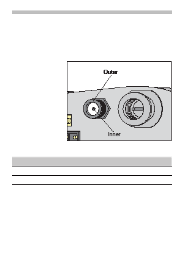
Interface description
Signal name PIN I/O Description
RF Inner I/O RF input/output
GND Outer X Frame connection
Purpose of the connectors/connections
GSM antenna
connector FME
A quad band antenna (GSM 850/900/1800/
1900) can be connected to the RF
interface.
The connection is implemented as a 50 Ω
FME coaxial jack.
Antenna connector
Copyright © Netkom Sp. z o.o. All rights reserved
35
Page 36

Interface description
Transmission type and method
Digitally modulated RF burst signal•
GMSK in accordance with GSM05.04•
Half duplex•
Bidirectional•
Interference immunity
Electrostatic discharge requirements in •
accordance with ETS 300-342-1
Electrical fast transient burst •
requirements (cable is >3 m)
Surge immunity requirements not •
specified
Electrostatic discharge requirements in •
accordance with ETS 300-342-1
Immunity RF common mode 0.15 – 80 •
MHz in accordance with ETS 300-342-1
36
Copyright © Netkom Sp. z o.o. All rights reserved
Page 37
Interface description
Signal name PIN I/O Description
RF Inner I/O RF input/output
GND Outer X Frame connection
GPS antenna
connector SMA
A GPS antenna can be connected to the
RF interface.
The connection is implemented as a 50 Ω
SMA coaxial jack.
Antenna connector
Purpose of the connectors/connections
Copyright © Netkom Sp. z o.o. All rights reserved
37
Page 38

Interface description
Transmission type and method
Digitally modulated RF burst signal•
Half duplex•
Bidirectional•
Interference immunity
Electrostatic discharge requirements in •
accordance with ETS 300-342-1
Electrical fast transient burst •
requirements (cable is >3 m)
Surge immunity requirements not •
specified
Electrostatic discharge requirements in •
accordance with ETS 300-342-1
Immunity RF common mode 0.15 – 80 •
MHz in accordance with ETS 300-342-1
38
Copyright © Netkom Sp. z o.o. All rights reserved
Page 39

Interface description
GSM status
LED
The green one indicates different
operating modes of the Netkom XT65
terminal.
To take advantage of this function the
LED mode must be activated with the
AT^SSYNC command. The LED can be
operated in two different display modes
(AT^SSYNC=1 or AT^SSYNC=2).
The following table lists the possible
patterns of status LED behavior, and
describes the ME operating status
indicated by each pattern if AT^SSYNC
parameter <mode>=1 and <mode>=2. To
better monitor the operating states while
power saving is enabled, we recommend
that priority be given to <mode>=2.
During the transition from one LED pattern
to another the “on” and/or “off” periods
of the LED may vary in length. This is
because an event that triggers the change
may occur any time and, thus, truncate the
current LED pattern at any point.
Copyright © Netkom Sp. z o.o. All rights reserved
39
Page 40

Interface description
LED behavior ME operating status if
Permanently off
600 ms on / 600ms off Limited Network Service: No SIM card
75 ms on / 3 s off IDLE mode: The mobile is
75 ms on / 75 ms off /
75 ms on / 3 s off
500 ms on / 50 ms off Packet switched data transfer is in
Permanently on Depending on type of call:
<n> ms on /
<n>ms off **
AT^SSYNC=1
ME is in one of the following modes:
- POWER DOWN mode
- AIRPLANE mode
- CHARGE ONLY mode
- NON-CYCLIC SLEEP mode
- CYCLIC SLEEP mode with no temporary
wake-up event in progress*
inserted or no PIN entered,
or network search in progress,
or ongoing user authentication,
or network login in progress.
registered to the GSM
network monitoring control
channels and user interactions).
No call is in progress.
One or more GPRS PDP
contexts activated.
progress.
Voice call: Connected to remote
party.
Data call: Connected to remote
party or
exchange of parameters while
setting up or disconnecting a call.
Not possible: With AT^SSYNC=1,
LED signalization is disabled
in SLEEP mode.
ME operating status if AT^SSYNC=2
ME is in one of the following modes:
- POWER DOWN mode
- AIRPLANE mode
- CHARGE ONLY mode
Same as for AT^SSYNC=1
Same as for AT^SSYNC=1
Same as for AT^SSYNC=1
Same as for AT^SSYNC=1
Same as for AT^SSYNC=1
SLEEP mode is activated (AT+CFUN
parameter <fun> ≠ 1), but the
ME is not registered to the
GSM network (e.g. SIM not
inserted or PIN not Entered,
and therefore, either no network
service or only Limited
Network Service is available.
* When a temporary wake-up event (for example a call, a URC, a packet switched transfer) occurs in CYCLIC SLEEP
mode the LED flashes according to the patterns listed above. See Section 2.9.1, Wake up the ME from SLEEP mode
for details on the various SLEEP modes and wake-up events.
** The duration of <n> and <m> depends on the network: In SLEEP mode, the module can only change its LED
status during intermittent wake-up periods when listening to paging information from the base station. Therefore the
values of <n> and <m> vary as follows: <n> = value from 471 ms to 2118 ms <m> = 3000 ms
40
Copyright © Netkom Sp. z o.o. All rights reserved
Page 41

Interface description
Programmable
LED
The programmable LED is connected to
GPIO1.
Copyright © Netkom Sp. z o.o. All rights reserved
41
Page 42

Interface description
Hardware settings
This chapter is only for advanced users.
You can switch on/off same parts of the
hardware. This is useful for better secure
of the Netkom XT65 Terminal and you
can save an energy (useful in automotive
applications), for example you can turn off
RS232, etc.
42
Copyright © Netkom Sp. z o.o. All rights reserved
Page 43

switch number function
1 On/0ff ADC1,2
2 On/0ff Inputs
3 On/0ff green LED
4 RESERVED
5 On/0ff I2CDAT line
6 On/0ff I2CCLK line
7 On/0ff 1-wire
8 On/0ff RS232
9 On/0ff VDD
10 RESERVED
Interface description
Copyright © Netkom Sp. z o.o. All rights reserved
43
Page 44

Startup
Before startup the SIM card must be
inserted in a deenergized state.
The terminal is ready for operation when
supply voltage is applied. It starts the
network search and registers with
network operator. Please read the
following conditions for switching the
terminal on and off:
44
Switching on/
off terminal
Switching on:
Simply applying supply voltage.
Switching off:
Software shutdown via an AT command.
It is advisable for a controlled shutdown of
the terminal.
In the case of this hardware shutdown,
the software is no longer able to respond
before the voltage is switched off. This
corresponds to a direct, unannounced
disconnection of the operating voltage.
Copyright © Netkom Sp. z o.o. All rights reserved
Page 45

Firmware
AT command control
SW update
The terminal is controlled and
programmed by means of AT commands.
The AT command structure corresponds
to the XT65 module. The AT commands
can be obtained from the Netkom support
page: www.nwm.pl.
A SW update for the terminal takes place
via the online connection.
Copyright © Netkom Sp. z o.o. All rights reserved
45
Page 46

Certification / maintenance
Certification
Maintenance tips
Hereby, Cinterion and Netkom, declares
that the cellular engine XT65 terminal
described in this manual is in compliance
with the essential requirements and other
relevant provisions of Directive 1999/5/EC
(R&TTE). The product is labeled with the
CE conformity mark CE1471.
Netkom XT65 Terminal is designed to
comply with the directives:
89/336/EC, 73/23/EC
2002/95/EC
2002/96/EC, 2003/108/EC
The Declaration of Conformity (DoC) has
been signed. In case of need, a copy of
the original DoC can be made available via
your distributor or system integrator.
Treat the SIM card with the same care •
as your credit card. Do not bend or
scratch the SIM card or expose it to
static electricity.
Wipe the terminal housing with a •
moist or antistatic cloth. Do not use a
chemical cleaning agent.
46
Copyright © Netkom Sp. z o.o. All rights reserved
Page 47

 Loading...