

Page 1

FUZZYSCAN FAMILY
Quick Start Guide
CORDLESS SCANNER
Bluetooth Version
Page 2
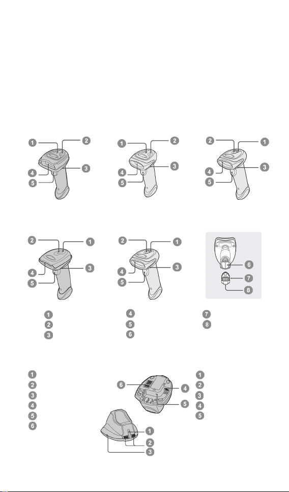
1
Central Indicator
Side Indicators
Paging/Reset Button
Host Interface Port
DC Power Jack
Quick Pair
Getting Familiar with Your FuzzyScan
Scan Window
Trigger
Battery Cavity
Link Indicator
Status Indicator
Beeper
Central Indicator
Reserved
Reserved
USB Port
DC
End Cap
Reset Button
Thank you for choosing Cino FuzzyScan Bluetooth Cordless Image Scanner.
Powered by the combination of cutting-edge FuzzyScan Imaging Technology
and Bluetooth wireless technology, it not only provides outstanding reading
performance, but also delivers the convenience and freedom of mobility. It’s
ideal for a broad range of applications to unleash your productivity with ease.
This document provides a quick reference for installation and operation. T he
complete documentation is available at www.cino.com.tw.
A780BT Series A680BT Series A660BT Series
F780BT & L780BT F680BT & L680BT
HB2112 Smart Cradle HB2100 USB Charging Cradle
Barcode
Power Jack
Page 3
2
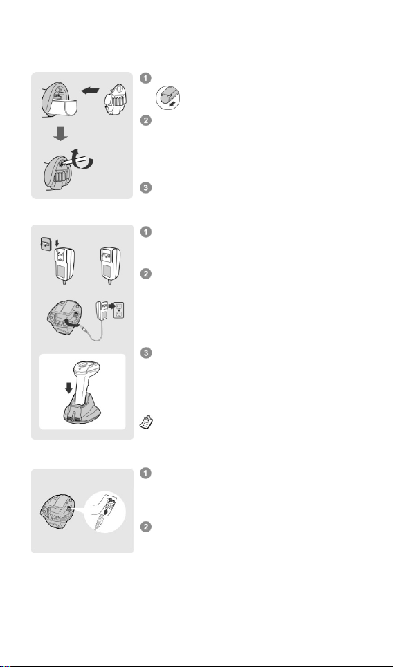
Preparations before Using
Choose the right plug and slot it into the power
supply unit cavity until a
is heard. Then
plug the power supply unit into the wall outlet.
Plug the DC power cord of power supply unit
into the DC
cradle
will
indicator
blinks blue once
.
If you use the charging
central
indicator
Place the scanner on the cradle. The status
indicator of scanner
if the
battery is not fully charged. When the battery is
fully charged, the status indicator will be
green
P
before its first
Ensure the battery contacts of the battery pack
s inside
Slide the battery pack into the battery cavity until
hearing a click sound. Press the
to power
on.
beeps when the
battery pack is installed properly
if the
battery pack still has power.
Sec
If USB 3.0 is available in your host device, both
b
be
supported by the
without using
external
If
is available in your host device,
we recommend using external power supply as
power source, because the power supplied from
USB 2.0 is not enough to support both battery
charging and regular operation
Install the Battery
Charge the Battery via Power Supply Unit
Charge the Battery via USB 3.0 Port
are facing the charging contact
the battery cavity.
The scanner will give 4
ure the end cap with the screw provided.
emit four beeps and the central
lights blue.
.
lease charge the new battery pack for 8 hours
attery charging and regular operation can
power supply.
only USB 2.0
trigger
and
“click”
Jack of the cradle. The smart
and side indicators lights red
use.
USB bus power
cradle, the
turns steady red
simultaneously. .
steady
Page 4

3
Decide Your Radio Link Mode
The FuzzyScan Bluetooth image scanner provides several radio link modes
to communicate with most host devices. When the Bluetooth-enabled host
device is not available, it can work with the smart cradle in PAIR mode
(peer-to-peer connection) or PICO mode (multiple connections) to provide a
plug-and-play cordless migration of your existing non-Bluetooth-enabled
host. Moreover, you can also use the scanner to work with Bluetooth-enabled
host via SPP mode or HID mode.
When the radio link is disconnected, the scanner is capable of reconnecting
automatically when it returns to the communication coverage. If you want to
change the radio link mode, please scan the “Uninstall” command to reset
the scanner to uninstall state.
PAIR Mode
If the Bluetooth device is not available in your existing system, PAIR mode is
the simplest plug-and-play solution. In this mode, a smart cradle can only
work with one scanner. The smart cradle not only provides the Bluetooth
radio link with the scanner, but also offers the legacy cabled interfaces to the
host device, including USB HID, USB COM and RS232 Serial.
PICO Mode
For the requirement of multiple connections, up to 7 scanners can be
connected to one smart cradle concurrently. If you want to un-pair all
scanners paired with the smart cradle, please press and hold the
paging/reset key of the smart cradle for more than 5 seconds. If you just want
to un-pair some of the paired scanners, please take those paired scanners to
scan the “Uninstall” command one by one.
HID Mode
Through the most useful HID service, the scanner can work as a Bluetooth
Keyboard. In this mode, the scanner will be discoverable by the radio
connection request issued by the remote host device.
SPP Master/Slave Mode
Through the standard SPP profile, the scanner can work as a Bluetooth
Serial Device. In SPP master mode, the scanner initiates the radio
connection request to the remote slave device. In SPP slave mode, the
scanner will be discoverable by the radio connection request issued by the
remote host device. Once the SPP slave pairing process is completed, the
radio link mode will be switched to SPP master automatically. This behavior
will enable auto-reconnection feature when the connection is lost.
Page 5
4
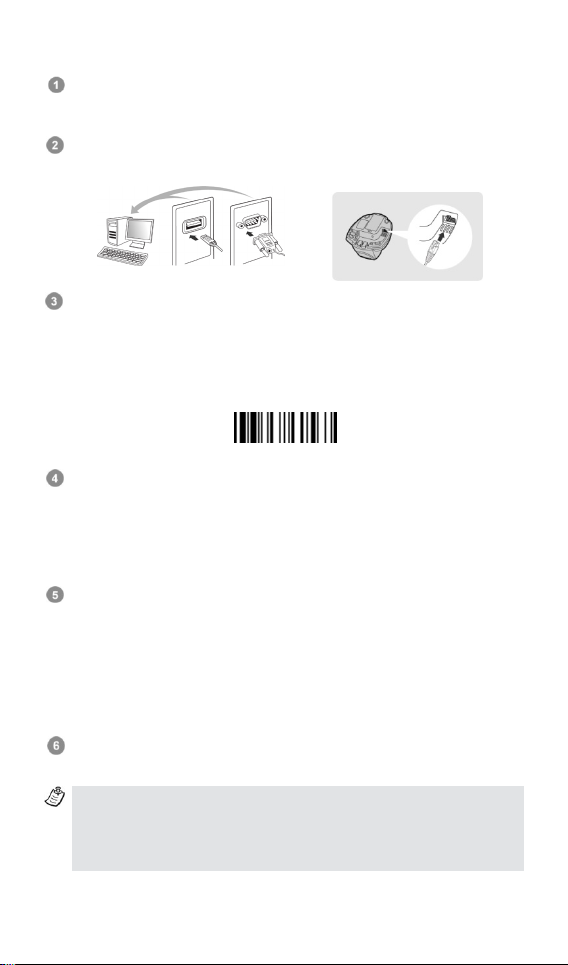
Use FuzzyScan in PAIR Mode
Uninstall
USB
RS232
Using a suitable interface cable, connect the smart cradle to your host
device. Turn on your host device. Make sure the smart cradle is receiving
power, in which case, its LED lights will be on.
Power on the scanner and keep it well within your smart cradle’s
Bluetooth range during the entire pairing process.
Please note that if the scanner is shipped together with a smart cradle,
they are pre-paired already. You will see the li nk indicator of scanner
gives 1 blue blink per 2.5 seconds and the central indicator of smart
cradle turns steady blue. If the scanner and smart cradle just give
alternative red and green blinks (in “Uninstall” state), please follow
step 4 to establish the connection between scanner and smart cradle.
Scan the smart cradle’s Quick Pair barcode with your scanner. This will
launch the pairing process during which the scanner will emit a series of
clicking sounds, and its link indicator will flash blue rapidly. Once pairing
is completed, the scanner will beep 4 times in ascending tone, and its link
indicator will flash blue every 2.5 seconds. The smart cradle’s center
indicator will be steady blue.
If the pairing process failed, you will hear the clicking sounds stop and the
link indicator of scanner will give 3 blue blinks per 2 seconds.
Thereafter, the scanner will continue to search for the smart cradle for
another 30 seconds before going into “Radio-Off” state. In the interim,
you may scan the “Uninstall” command to set the scanner to the
“Uninstall” state. If the scanner has entered radio-off state already, you
can wake it up by pressing its trigger; this will also cause the scanner to
re-attempt pairing.
Scan the corresponding host interface quick set command to complete
the installation.
The default host interface of smart cradle is preset to USB HID. If you
want to set the host interface to USB COM, you have to install the
USB virtual COM driver into your host device before using the
scanner. Please visit CINO website to download the driver.
Page 6

5
Use FuzzyScan in PICO Mode
Uninstall
USB
RS232
Using a suitable interface cable, connect the smart cradle to your host
device. Turn on your host device. Make sure the smart cradle is receiving
power, in which case, its LED lights will be on. Create a Quick Pair
barcode for PICO mode and have it ready. Please refer to the FuzzyScan
Bluetooth Scanner Reference Manual for instructions on how to prepare
such a barcode.
Power on the scanner and keep it well within your smart cradle’s
Bluetooth range during the entire pairing process.
Please note that if the scanner is shipped together with a smart cradle,
they are pre-paired in PAIR mode already. The scanner’s link should emit
1 blue blink every 2.5 seconds and the smart cradle’s central indicator
should be a steady blue. Scan the “Uninstall” barcode below to unpair
the scanner and smart cradle. Their indicators will then emit alternating
red and green blinks.
Scan the Quick Pair barcode for PICO mode (which you have created in
advance) with your scanner. This will launch the pairing process during
which the scanner will emit a series of clicking sounds, and its link
indicator will flash blue rapidly.
Once pairing is completed, the scanner will beep 4 times in ascending
tone, and its link indicator will flash blue every 2.5 seconds. As for the
smart cradle, its center indicator will display a steady blue light and its
side indicators will be steady green.
As applicable, repeat the above procedures to pair other scanners with
the same smart cradle (up to 7 scanners).
Scan the corresponding host interface quick set command to complete
the installation.
The default host interface of smart cradle is preset to USB HID. If you
want to set the host interface to USB COM, you have to install the
USB virtual COM driver into your host device before using the
scanner. Please visit CINO website to download the driver.
Page 7

6
Use FuzzyScan in HID Mode
Uninstall
HID Mode
Ensure the battery is fully charged. Power on the scanner within radio
coverage and ensure the status indicator of scanner gives alternative
red and green blinks (in “Uninstall” state). If your scanner is not in the
Uninstall state, please scan the “Uninstall” command first.
If your remote host is equipped with latest Bluetooth drivers, or it’s an iOS
or Android device, it is recommended to use “HID Mode”.
Once you had scanned the “HID Mode” barcode, the scanner’s link
indicators will blink blue 3 times every 2 seconds during the search
process. You have to execute the Bluetooth Discovery procedure to find
nearby Bluetooth device, then select “F(L/A)xxxBT-xxxx” (the xxxx are the
last 4 digits of its MAC address).
The scanner will emit 4 beeps in ascending tone to indicate the
connection is established. The scanner’s link indicators will also flash
blue every 2.5 seconds to indicate a radio-connected state.
If the scanner is not pair with the host device within 1 minute after
scanning the above command, it will enter radio-off state automatically.
You can wake up the scanner by pressing its trigger, this will also cause
the scanner to re-attempt pairing.
The installation procedure may vary depending on different remote
host devices, operating systems and the Bluetooth drivers. Please
consult your professional IT consultant to obtain necessary support.
Page 8

7
Use FuzzyScan in SPP Mode
Establish SPP Master Connection
Look for the Bluetooth host device’s MAC address under its “Hardware”
or “Bluetooth” settings. You will need this MAC address later on.
Ensure that a virtual COM port is available on your host device for
scanner connection. If not, perform the steps required on your host
device to add one. For example, go to “Local Services” under “Bluetooth
Advanced Settings” and click on “Add Serial Services” to add a virtual
incoming COM port.
Power on the scanner within radio coverage and make sure its status
indicator gives alternative red and green blinks (in “Uninstall” state). If
not, scan the “Uninstall” barcode to release its current pairing.
Scan the “SPP Master Simple Mode” barcode . The scanner’s status
indicator will turn steady red immediately.
Scan the 12 option codes (see Appendix) that correspond to your host
device’s MAC address, then scan the “FIN” barcode. The scanner will
emit a series of clicking sounds and its link indicators will flash blue
rapidly.
Launch your terminal application to connect it with the scanner. The
scanner will emit 4 beeps in ascending tone to indicate radio connection,
and its link indicator will flash blue every 2.5 seconds.
If the scanner fails to pair with host device within 30 seconds, its link
indicator will give 3 blue blinks every 2 seconds. Thereafter, the scanner
will continue to search for your host device for another 30 seconds before
going into “Radio-Off” state. In the interim, you may scan the “Uninstall”
command to set your scanner to the “Uninstall” state. If the scanner has
entered radio-off state already, you can wake the scanner by pressing its
trigger; this will al so cause the scanner to re-attem pt pairing.
The above procedures are based on popular Windows operation
environment. But the installation procedure may vary depending on
different remote host devices, operating systems and the Bluetooth
drivers. Please consult your professional IT consultant to obtain
necessary support if any problem is arouse during the installation
processes. For more detailed information, please visit CINO website.
Uninstall
SPP Master Simple Mode
Page 9

8
Uninstall
SPP Slave Simple Mode
Establish SPP Slave Connection
Ensure that a virtual COM port is available on your host device for
scanner connection. If not, perform the steps required on your host
device to add one. For example, go to “Local Services” under “Bluetooth
Advanced Settings” and click on “Add Serial Services” to add a virtual
incoming COM port.
Power on the scanner within radio coverage, and make sure its status
indicator gives off alternating red and green blinks (in “Uninstall”
state). If not, scan the “Uninstall” barcode to release its current pairing.
Scan the “SPP Slave Simple Mode” barcode. The scanner’s status
indicator will flash blue 3 times every 2 seconds while it waits for the
pairing process to be launched.
Execute the Bluetooth Discovery procedure to find all available Bluetooth
device list in your remote host. You will see „‟F(L/A)xxxBT-xxxx‟ (the xxxx
are the last 4 digits of its MAC address) is shown in the list if the scanner
is successfully discovered. Perform the steps required on your host
device to activate the pairing (e.g. tapping or double clicking on the model
number, etc.). During the pairing process, the scanner will emit a series of
clicking sounds and its link indicators will flash blue rapidly.
Launch your terminal application to build the connetion with the scanner.
The scanner will emit 4 beeps in ascending tone to indicate the radio is
connected, and its link indicator will flash blue every 2.5 seconds.
If the scanner is not paired with the host device within 1 minute after
scanning the above command, it will enter radio-off state automatically.
You can wake up the scanner by pressing its trigger, this will also cause
the scanner to re-attempt pairing.
The above procedures are based on popular Windows environment.
But the installation procedure may vary depending on different remote
host devices, operating systems and the Bluetooth drivers. Please
consult your professi onal IT consultant to obtain necessary support if
any problem has been encountered during the installation processes.
For more detailed information, please visit CINO website.
Page 10

9
Out-of-range Scanning
Disable Out-of-range Scanning
Disable Auto-sense
When the radio connection is established between scanner and remote host
device, the scanner will transmit each scanned data right after scanning the
barcode. However, the default of the scanner is unable to scan any barcode
data when it loses the radio connection with the remote host device. If you
enable the out-of-range scanning function, the scanner is able to continue
scanning barcode data while it is out of radio coverage. All scanned data will
be temporarily stored into the memory buffer until radio link resumed.
Enable Out-of-range Scanning
In case of the scanner is out of radio coverage, you will hear 4 beeps in
descending tone to indicate the radio connection lost. The scanner’s link
indicators will blink blue 3 times per 2 seconds. Once the scanner is back
to radio coverage, you will hear 4 beeps in ascending tone to indicate the
radio connection rebuilt and the scanner’s link indicators blink blue once per
2.5 seconds. At the same time, all the stored scanned data will be
transmitted automatically right after the radio link is resumed.
◆
Presentation Scanning
The Presentation Scanning is designed for hand-free applications for user’s
convenience. If the “Presentation Scanning Auto-sense” function is enabled,
the scanner is capable of automatically switching to presentation mode as
soon as you place it onto the SmartS tand or cradle.
Enable Auto-sense
In presentation mode, you can select higher sensitivity level though the
setting of Presentation Sensitivity when using scanner in a dim ambient
lighting environment. For the setting of Presentation Sensitivity, please refer
to Programming Manual for details.
◆
Power off the Scanner
By default, the scanner goes off if the scanner is not used during the
user-defined time-out duration. You also can power off the scanner by
scanning the “Power Off” command. If you want to activate the scanner,
please press the trigger key.
Power Off
Page 11

10
Batch Scanning (Inventory Mode)
Thanks to the specially designed Batch Scanning function, the scanner is
capable of storing up to 100,000 EAN-13 barcode data. It is an ideal
cost-saving solution for inventory applications.
Once you scan the “Enter Batch Scanning” command to activate this function,
all scanned barcode data will be stored into the memory storage, and the
status indicator of scanner will give green blink at regular interval during
batch scanning. You can scan and store the barcode data till the memory
storage is full. If the storage is full, you will hear 2 long beeps and the status
indicator will give 2 red blinks to indicate out of storage. To terminate the
batch scanning, please scan the “Exit Batch Scanning” command.
Enter Batch Scanning
Exit Batch Scanning
Use Quantity Feature
The scanner will support quantity feature when it enters batch scanning.
When you use quantity feature, the quanity information and scanned barcode
data will be stored into the memory storage together. You can enter the
quantity i nformation from 1 to 9999 by scanning the following quantity
commands right after you had scanned the barcode data.
Quantity 3
Quantity 0 Quantity 7
Quantity 4
Quantity 1 Quantity 8
Quantity 5
Quantity 2 Quantity 9
Quantity 6
Page 12

11
As many times as the quantity indicates ◆
<Quantity><Field Delimiter><Scanned Data>
<Scanned Data><Field Delimiter><Quantity>
Transmit Stored Data
Scan command or Place
Scanner onto the Cradle
Delete Last Scanned Data
There are three ways to output the stored barcode data and quantity
information. The preset output format is to transmit the stored barcode data
as many times as the quantity indicated. But you can also set the scanner to
outpt the stored barcode data together with quantity information in two fields,
and a prest delimter “,“ will be output in between. To fulfill different
application requirements, both the delimiter and output sequence can be
changed as well.
How to Transmit Stored Data
The scanner is preset to transmit all stored data by scanning the “Transmit
Stored Data” command. During the transmission, the scanner will emit
continuous short clicks and the link indicator will blink blue. Then the scanner
will give two short beeps after data transmission is completed.
But you are able to set the scanner to transmit the stored data by placing the
scanner onto the cradle as well.
Scan Barcode
Command ◆
Place Scanner
onto the Cradle
How to Delete the Last Scanned Data
If you scanned a wrong barcode, the “Delete Last Scanned Data’’ command
is helpful to recover mistake. By scanning the ‘’Delete Last Scanned Data’’
command, the last stored data will be deleted.
Page 13

12
Link Mode Quick Set
United Kingdom-UK
Spain
HID Mode
SPP Master Simple Mode SPP Slave Simple Mode
UNINSTALL
Host Interface Quick Set (for Smart Cradle only)
USB HID
Standard Mode ◆
RS232 Serial
USB Com Port
Keyboard Layout Quick Set
USA ◆
France
Germany
Canadian French
Emulation
USB HID Turbo Mode
Latin America
Nertherlands
Japan
Page 14

13
System Commands
System Information
PowerTool Host Link
Power Off
Clone
Presentation Mode
FIN (Finish)
END (Exit)
Paging Master Default
Switch On-screen
Keyboard
Factory Default
Save Configuration
Operation Mode Quick Set
Trigger Mode ◆
Option Codes
0
1
2
3
4
5
6
8
C
9
D
A
E
B
7 F
Page 15

14
Indications
Items
Link Indicator
Beeping
Radio connection
1 blue blink per 2.5 sec.
Off
Radio disconnection
3 blue blinks per 2 sec.
Off
During connection
Quick blue blinks
Short clicks
Radio connection built
1 blue blink per 2.5 sec.
4 beeps in ascending tone
Radio connection lost
3 blue blinks per 2 sec.
4 beeps in descending tone
Data Transmission
Quick blue blink
Short clicks
Items
Status Indicator
Beeping
Under charging (on cradle)
Steady red
Off
Fully charged (on cradle)
Steady green
Off
Under batch scanning
1 green blink per 2.5 sec.
Off
Pair failure
3 blue blinks per 2 sec.
Off
Out of memory
2 red blinks
2 long beeps
Battery power low
1 red blink at regular interval
1 beep at regular interval
Battery power extremely low
1 red blink
8 beeps
Good read
1 green blink
1 good read beep
Under Configuration
Steady red
Off
Uninstall state
Alternative red and green blinks
Off
Upgrade state
Steady red
Short click
Time out warning
Off
3 long beeps
Paged by smart cradle
Off
6 page beeps
Radio-off / Battery no power
Off
Off
Power Off
Off
Off
Indicators
Central
Side
Power on
Blink blue once
Off
Power on beeps
Smart Cradle Upgrade State
Off
Steady red
Short clicks
Off
Alternative red-green
blinks
Radio Connected
Steady blue
Steady Green
Off
Radio Disconnected
Off
Steady red
Off
Radio Connected
Steady blue
Off
Off
Radio Disconnected
Off
Steady red
Off
by scanner
PICO Mode
Steady blue
Steady green
6 page beeps
PAIR Mode
Steady blue
Off
6 page beeps
Items
Central Indicator
Beeping
Power on
Steady blue
Off
Side Indicators
Scanner Indications
HB2112 Smart Cradle Indications
Central Indicator
Items
Uninstall state
PICO Mode
PAIR Mode
Smart cradle paged
HB2100 USB Charging Cradle Indication
Beeping
Off
Page 16

www.cino.com.tw
FuzzyScan Bluetooth Cordless Scanner Quick Start Guide
International Edition, Rev. C3
P/N: YMBB030000C3EN1
Disclaimer
Cino makes no warranty of any kind with regard to this publication, including, but not limited to, the
implied warranty of merchantability and tness for any particular purpose. Cino shall not be liable for
errors contained herein or for incidental consequential damages in connection with the furnishing,
performance, or use of this publication. This publication contains proprietary information that is protected
by copyright. All rights are reserved. No part of this publication may be photocopied, reproduced or
translated into any language, in any forms, in an electronic retrieval system or otherwise, without prior
written permission of Cino. All product information and specications shown in this document may be
changed without prior notice.
© COPYRIGHT CINO GROUP • PC WORTH INT’L CO., LTD. ALL RIGHT RESERVED.
Warranty
Cino warrants its products against defects in workmanship and materials from the date of shipment,
provided that the product is operated under normal and proper conditions. The warranty provisions and
durations are furnished by dierent warranty programs. The above warranty does not apply to any
product which has been (i) misused; (ii) damaged by accident or negligence; (iii) modied or altered by the
purchaser or other party; (iv) repaired or tampered by unauthorized representatives; (v) operated or stored
beyond the specied operational and environmental parameters; (vi) applied software, accessories or
parts are not supplied by Cino; (vii) damaged by circumstances out of Cino’s control, such as, but not
limited to, lightning or uctuation in electrical power. Any defective product must follow the warranty
program and RMA procedures to return Cino for inspection.
Regulatory
FCC part 15B, FCC part 15C
EN55022 EN55024
EN301 489-1 & 489-17, EN300 328
EN61000-3-2, EN61000-3-3, EN60950-1
Clause 2, Article 58-2 of Radio Waves Act.
Class B ITE
MIC T401
AS/NZS CISPR 22 Class B
AS/NZS 4268
CNS13438, CNS14336
LP0002
LED Eye Safety
Laser Eye Safety
IEC62471 Exempt group
IEC60825-1 Class 1
 Loading...