

Cineversum BarcoGraphics 808s Owners Manual
GRAPHICS
R9000904
OWNER'S MANUAL
808s

BARCO PROJECTION SYSTEMS
Date :
160403
GRAPHICS
R9000904
OWNER'S MANUAL
Revision :
01
808s
Art. No. :
R5976283

Due to constant research, the information in this manual is subject to change without notice.
Produced by BARCO NV, April 2003.
All rights reserved.
Trademarks are the rights of their respective owners.
Printed in Belgium
BARCO n.v./Projection Systems
Noordlaan 5
B-8520 Kuurne
Belgium
Tel : +32/56/368211
Fax : +32/56/351651
E-mail : sales.bps@barco.com
Visite Barco at the web : http://www.barco.com
Printed in Belgium

Table of contents
TABLE OF CONTENTS
i
TABLE OF CONTENTS ............................................................................................................................................................................... I -1
SAFETY INSTRUCTIONS .......................................................................................................................................................................... 1 -1
On safety ........................................................................................................................................................................................... 1-1
On installation .................................................................................................................................................................................... 1-2
On servicing ...................................................................................................................................................................................... 1-2
On cleaning ........................................................................................................................................................................................1-2
On repacking .....................................................................................................................................................................................1-2
On illumination .................................................................................................................................................................................... 1 -2
LOCATION AND FUNCTIONS OF CONTROL .......................................................................................................................................... 2-1
Rear panel terminology ...................................................................................................................................................................... 2-1
Control panel terminology .................................................................................................................................................................. 2-2
a. The Local Keypad ......................................................................................................................................................................... 2-2
b. RCU control panel terminology ......................................................................................................................................................2-2
CONNECTIONS .......................................................................................................................................................................................... 3-1
AC Power (mains) Cord Connection ................................................................................................................................................ 3-1
Power Check ..................................................................................................................................................................................... 3-1
Switching On/Off .............................................................................................................................................................................. 3-1
Signal Input Connection to the Projector : .........................................................................................................................................3-2
Connecting a RGB Analog source to port 3. ....................................................................................................................................3-3
Connecting a RGB Analog source to port 4/5. .................................................................................................................................3-3
Connecting a RGB Analog source with Tri-level sync to port 4/5. .................................................................................................. 3-4
Connecting a Component Video source to port 4/5. ........................................................................................................................ 3 -4
Connecting a Component Video source with Tri-level sync to port 4/5. .........................................................................................3-4
Connecting a computer to the projector. ..........................................................................................................................................3-5
Peripheral equipment ........................................................................................................... ..............................................................3 -5
Connecting a RCVDS 05 switcher to the projector. .........................................................................................................................3-5
Connecting a VS05 switcher to the projector. ................................................................................................................................. 3-5
CONTROLLING .......................................................................................................................................................................................... 4 -1
Battery installation in the RCU. ..........................................................................................................................................................4-1
How to use your RCU ....................................................................................................................................................................... 4-2
Projector Address .............................................................................................................................................................................4-2
How to display a projector address? ...............................................................................................................................................4-2
How to program an address into the RCU? ..................................................................................................................................... 4-3
Input selection ...................................................................................................................................................................................4 -3
Analog Picture Controls .................................................................................................................................................................... 4-3
Controlling chained projectors. .........................................................................................................................................................4-4
START UP OF THE ADJUSTMENT MODE ............................................................................................................................................... 5-1
Adjustment Mode ...............................................................................................................................................................................5-1
RANDOM ACCESS ADJUSTMENT MODE ............................................................................................................................................... 6-1
Starting-Up the Random Access Adjustment mode. ........................................................................................................................ 6-1
Overview 'Random Access Adjustment' mode ................................................................................................................................6-1
Selecting Setup Pattern .....................................................................................................................................................................6-3
Internal Cross Hatch Pattern ............................................................................................................................................................. 6-3
Random access adjustment mode selection menu. .........................................................................................................................6-4
Picture Tuning ....................................................................................................................................................................................6-4
Color Balance .................................................................................................................................................................................... 6-4
Sync Fast/Slow Adjustment ............................................................................................................................................................. 6-5
Peaking ..............................................................................................................................................................................................6-5
Clamp Tuning ..................................................................................................................................................................................... 6-5
Port 2 : Video or S-Video .................................................................................................................................................................. 6-6
Line Doubler (option) ......................................................................................................................................................................... 6-6
Color Select ....................................................................................................................................................................................... 6-6
Focusing ............................................................................................................................................................................................6-7
Focusing color select. ....................................................................................................................................................................... 6-7
Midpoint focusing .............................................................................................................................................................................. 6- 7
Top image focusing ........................................................................................................................................................................... 6 -7
Bottom image focusing ...................................................................................................................................................................... 6-7
Left image focusing ........................................................................................................................................................................... 6-7
Right image focusing .........................................................................................................................................................................6-7
Blue on source .................................................................................................................................................................................. 6-7
5976283 BARCOGRAPHICS 808s 160403
i-1

Table of contents
Geometry Adjustments ...................................................................................................................................................................... 6-8
Horizontal Phase Adjustment ............................................................................................................................................................ 6- 8
Raster Shift Adjustment .................................................................................................................................................................... 6-9
Left-Right (east-west) Adjustments .............................................................................................................................................. 6-10
Seagull correction .......................................................................................................................................................................... 6-11
Left Side Correction ....................................................................................................................................................................... 6-11
Top-Bottom (north-south) Adjustments ......................................................................................................................................... 6-12
Seagull Correction .......................................................................................................................................................................... 6-13
Horizontal Size Adjustment ............................................................................................................................................................ 6-13
Vertical Linearity Adjustment ......................................................................................................................................................... 6-14
Vertical Size Adjustment ................................................................................................................................................................ 6-14
Blanking Adjustments ..................................................................................................................................................................... 6-15
Convergence Adjustment .............................................................................................................................................................. 6-16
Coarse Convergence Adjustment. ................................................................................................................................................ 6-16
Horizontal sides .............................................................................................................................................................................. 6-16
Vertical corners ............................................................................................................................................................................. 6-17
Fine Convergence Adjustment. ...................................................................................................................................................... 6-17
SERVICE MODE ......................................................................................................................................................................................... 7- 1
Starting up the Service mode. ........................................................................................................................................................... 7-1
Overview flowchart 'Service' mode. ................................................................................................................................................ 7-1
Identification ....................................................................................................................................................................................... 7-2
Copy a block ...................................................................................................................................................................................... 7-2
Deletion of blocks ..............................................................................................................................................................................7-3
Deleting block by block ......................................................................................................................................................................7-3
Deletion of all blocks .......................................................................................................................................................................... 7-3
Change password ............................................................................................................................................................................ 7-4
Change Language .............................................................................................................................................................................7-4
Run time ............................................................................................................................................................................................. 7-4
Set to midposition .............................................................................................................................................................................. 7-5
Undo Midposition ............................................................................................................................................................................... 7 -5
Convergence Mid .............................................................................................................................................................................. 7-5
Undo Convergence Mid(position) ..................................................................................................................................................... 7-5
Dynamic Astigmatism (spot shape adjustment) ............................................................................................................................... 7-6
G2 Adjust ........................................................................................................................................................................................... 7-7
Gamma corrections ........................................................................................................................................................................... 7-7
CRT run in cycle ................................................................................................................................................................................7-7
Projector Warm Up ............................................................................................................................................................................ 7-8
CRT Drive Mode ................................................................................................................................................................................. 7- 8
MESSAGES, WARNINGS AND FAILURE CODES ..................................................................................................................................... 8-1
OPTIONS .................................................................................................................................................................................................... 9- 1
Hardwired RCU. ................................................................................................................................................................................ 9-1
Projector Control software ............................................................................................................................................................... 9-1
RCVDS 05 Source Selector .............................................................................................................................................................. 9- 1
VS05 Switcher .................................................................................................................................................................................. 9-1
MAGIK Interface ................................................................................................................................................................................9-2
Adapter and communication cables .................................................................................................................................................9 -2
Appendix A : Adjustment blocks and source numbers 90 - 99 ............................................................................................................... A -1
i-2 5976283 BARCOGRAPHICS 808s 160403
Safety Instructions
1
SAFETY INSTRUCTIONS
Notice on Safety
This equipment is built in accordance with the requirements of the
international safety standards EN60950, UL 1950 and CSA C22.2
No.950, which are the safety standards of information technology
equipment including electrical business equipment.
These safety standards impose important requirements on the use
of safety critical components, materials and isolation, in order to
protect the user or operator against risk of electric shock and energy
hazard, and having access to live parts.
Safety standards also impose limits to the internal and external
temperature rises, radiation levels, mechanical stability and strength,
enclosure construction and protection against the risk of fire.
Simulated single fault condition testing ensures the safety of the
equipment to the user even when the equipment's normal operation
fails.
INSTALLATION INSTRUCTIONS
Before operating this equipment please read this manual
thoroughly, and retain it for future reference.
Installation and preliminary adjustments should be
performed by qualified BARCO personnel or by author-
ized BARCO service dealers.
OWNER’S RECORD
The part number and serial number are located at the back side of the
projector. Record these numbers in the spaces provided below.
Refer to them whenever you call upon your BARCO dealer regarding
this product.
PART NUMBER :
SER. NUMBER :
DEALER :
FEDERAL COMMUNICATION COMMISSION (FCC STATEMENT)
This equipment has been tested and found to comply with the limits
of a class A digital device, pursuant to Part 15 of the FCC Rules. These
limits are designed to provide reasonable protection against harmful
interference when the equipment is operated in a commercial
environment. This equipment generates, uses and can radiate radio
frequency energy and, if not installed and used in accordance with
the instruction manual, may cause harmful interference to radio
communications. Operation of this equipment in a residential area is
likely to cause harmful interference in which case the user will be
required to correct the interference at his own expense.
Note :
The use of shielded cables is required to comply within the limits of
Part 15 of FCC rules and EN55022.
* All the safety and operating instructions should be read before using
this unit.
* The safety and operating instructions manual should be retained for
future reference.
* All warnings on the equipment and in the documentation manuals
should be adhered to.
* All instructions for operating and use of this equipment must be
followed precisely.
On safety
1. This product should be operated from an AC power source.
This projector may be connected to an IT-power system.
Operating AC power voltage of the projector:
Power voltage is autoranging between 100V (-10%) and 240V (+6%)
If you are not sure of the type of AC power available, consult your
dealer or local power company.
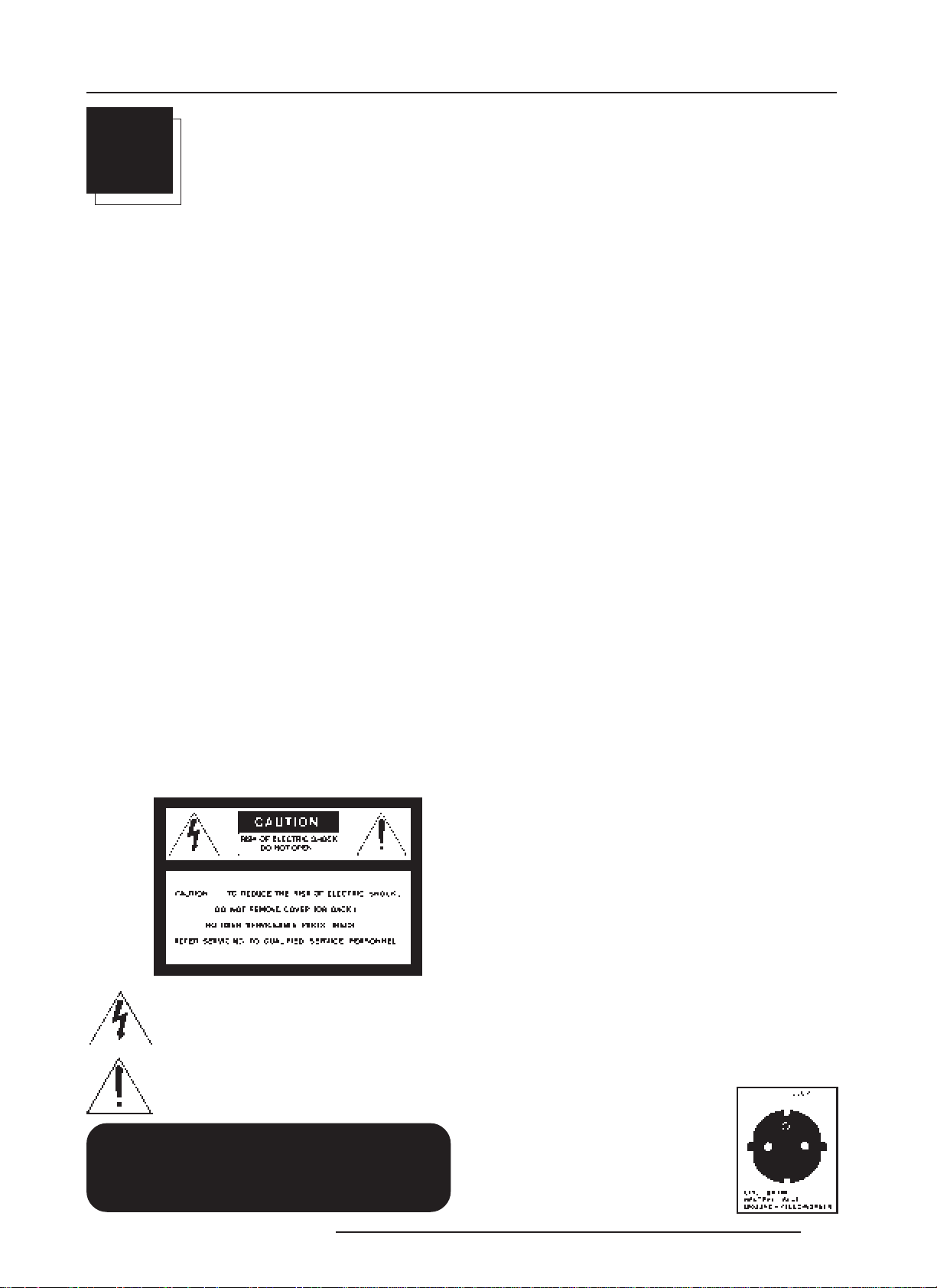
The lightning flash with an arrowhead within a
triangle is intended to tell the user that parts inside this
product may cause a risk of electrical shock to
persons.
The exclamation point within a triangle is intended to
tell the user that important operating and/or servicing
instructions are included in the technical documentation for this equipment.
WARNING
TO PREVENT FIRE OR ELECTRICAL SHOCK
HAZARD, DO NOT EXPOSE THIS EQUIPMENT TO
RAIN OR MOISTURE
5976283 BARCOGRAPHICS 808s 160501
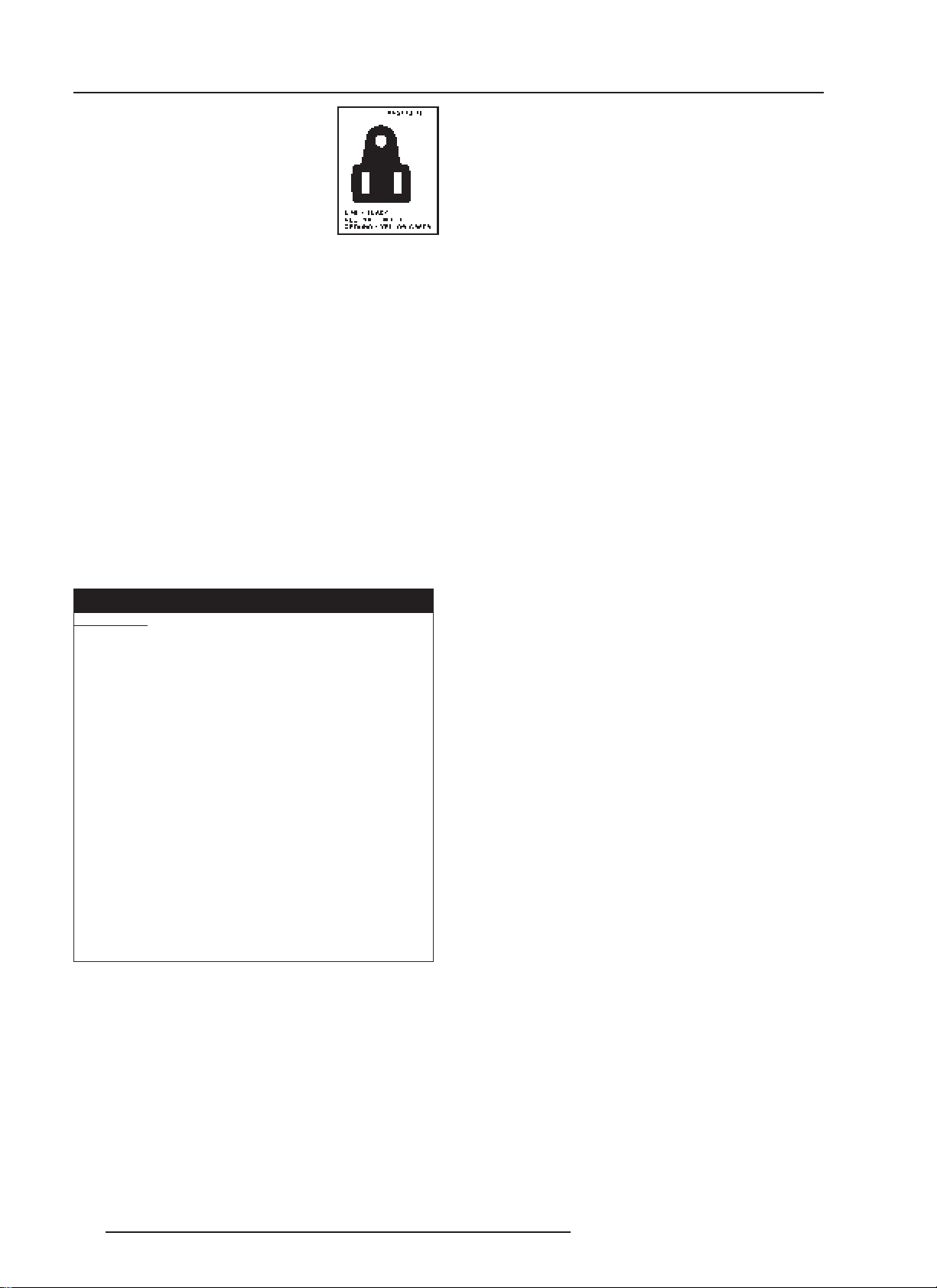
2. This product is equipped with a 3-wire grounding plug, a plug having
a third (grounding) pin. This plug will only fit into a grounding-type
power outlet. This is a safety feature. If you are unable to insert the
plug into the outlet, contact your electrician to replace your obsolete
outlet. Do not defeat the purpose of the grounding-type plug.
WARNING FOR THE CUSTOMERS: THIS APPARATUS MUST BE
GROUNDED (EARTHED) via the supplied 3 conductor AC power
cable.
(If the supplied power cable is not the correct one, consult your
dealer.)
A. Mains lead (Power cord) with CEE 7 plug:
The wires of the mains lead are colored in accordance with the
following code.
Green and yellow:earth (safety earth)
Blue: neutral
Brown: line (live)
1-1
Safety Instructions
B. Power cord with ANSI 73.11 plug:
The wires of the power cord are colored in
accordance with the following code.
Green/yellow: ground
White: neutral
Black: line (live)
On servicing
Do not attempt to service this product yourself, as opening or
removing covers may expose you to dangerous voltage potentials
and risk of electric shock!
Refer all servicing to qualified service personnel.
Unplug this product from the wall outlet and refer servicing
3. Do not allow anything to rest on the power cord. Do not locate this
product where persons will walk on the cord.
To disconnect the cord, pull it out by the plug. Never pull the cord itself.
4. If an extension cord is used with this product, make sure that the
total of the ampere ratings on the products plugged into the extension
cord does not exceed the extension cord ampere rating. Also make
sure that the total of all products plugged into the wall outlet does not
exceed 15 amperes.
5. Never push objects of any kind into this product through cabinet
slots as they may touch dangerous voltage points or short out parts
that could result in a risk of fire or electrical shock.
Never spill liquid of any kind on the product. Should any liquid or solid
object fall into the cabinet, unplug the set and have it checked by
qualified service personnel before resuming operations.
6. Lightning - For added protection for this video product during a
lightning storm, or when it is left unattended and unused for long
periods of time, unplug it from the wall outlet. This will prevent damage
to the projector due to lightning and AC power-line surges.
to qualified service personnel under the following conditions:
a. When the power cord or plug is damaged or frayed.
b. If liquid has been spilled into the equipment.
c.If the product has been exposed to rain or water.
d. If the product does not operate normally when the operating
instructions are followed.
Note : Adjust only those controls that are covered by the operating
instructions since improper adjustment of the other controls may
result in damage and will often require extensive work by a qualified
technician to restore the product to normal operation.
e. If the product has been dropped or the cabinet has been damaged.
f. If the product exhibits a distinct change in performance, indicating
a need for service.
Replacement parts - When replacement parts are required, be
sure the service technician has used original BARCO replacement
parts or authorized replacement parts which have the same characteristics as the BARCO original part. Unauthorized substitutions
may result in degraded performance and reliability, fire, electric shock
On installation
CAUTION FIRE HAZARD
WARNING: DO NOT PLACE FLAMMABLE OR
or other hazards. Unauthorized substitutions may void warranty.
Safety check - Upon completion of any service or repairs to this
projector, ask the service technician to perform safety checks to
determine that the product is in proper operating condition.
COMBUSTIBLE MATERIALS NEAR PROJECTOR !
BARCO large screen projection products are designed and manufactured to
meet the most stringent safety regulations. This projector radiates heat on
its external surfaces and from ventilation ducts during normal operation,
which is both normal and safe.
Exposing flammable or combustible materials into close proximity of this
projector could result in the spontaneous ignition of that material, resulting
in a fire. For this reason, it is absolutely necessary to leave an exclusion
zone around all external surfaces of the projector whereby no flammable or
combustible materials are present. The exclusion zone must be not less
than 10 cm (4) for BARCO Retro Projectors and not less than 40 cm (16)
for all other BARCO projectors. Do not cover the projector with any material
while the projector is in operation.
Keep flammable and combustible materials away from the projector at all
times. Mount the projector in a well ventilated area away from sources of
ignition and out of direct sun light. Never expose the projector to rain or
excessive moisture. In the event of fire, use sand,
extinguishers; never use water on an electrical fire.
Always have service performed on this projector by authorized BARCO
service personnel. Always insist on genuine BARCO replacement parts.
Never use non-BARCO replacement parts as they may degrade the safety
of this projector.
This product complies to standards set by Underwriters Laboratories, Inc., Canadian
Standards Association, and meets all applicable U.S. / Canadian and European
government regulations or directives.
CO
, or dry powder fire
2
1. Do not place this equipment on an unstable cart, stand, or table.
The product may fall, causing serious damage to it.
2. Do not use this equipment near water.
3. Slots and openings in the cabinet and the back or bottom are
provided for ventilation; to ensure reliable operation of the product and
to protect it from overheating, these openings must not be blocked
or covered. The openings should never be blocked by placing the
product on a bed, sofa, rug, or other similar surface. This product
should never be placed near or over a radiator or heat register.
The projector should not be placed in a built-in installation or enclosure
unless proper ventilation is provided.
4. Do not block the projector cooling fans or free air movement under
and around the projector. Loose papers or other objects may not be
nearer to the projector than 4" on any side.
1-2 5976283 BARCOGRAPHICS 808s 160501
On cleaning
Unplug this product from the wall outlet before cleaning. Do
not use liquid cleaners or aerosol cleaners. Use a damp cloth
for cleaning.
- To keep the cabinet looking brand-new, periodically clean it with a
soft cloth. Stubborn stains may be removed with a cloth lightly
dampened with mild detergent solution. Never use strong solvents,
such as thinner or benzine, or abrasive cleaners, since these will
damage the cabinet.
- To ensure the highest optical performance and resolution, the
projection lenses are specially treated with an anti-reflective
coating, therefore, avoid touching the lens. To remove dust on the
lens, use a soft dry cloth. Do not use a damp cloth, detergent
solution, or thinner.
On repacking
Save the original shipping carton and packing material; they will come
in handy if you ever have to ship your equipment. For maximum
protection, repack your set as it was originally packed at the factory.
On illumination
In order to obtain the best quality for the projected image, it is essential
that the ambient light which is allowed to fall on the screen be kept
to an absolute minimum.
When installing the projector and screen, care must be taken to avoid
exposure to ambient light directly on the screen. Avoid adverse
illumination on the screen from direct sunlight or fluorescent lighting
fixtures.
The use of controlled ambient lighting, such as incandescent spot light
or a dimmer, is recommended for proper room illumination. Where
possible, care should also be taken to ensure that the floors and walls
of the room in which the projector is to be installed are non-reflecting,
dark surfaces. Brighter surfaces will tend to reflect and diffuse the
ambient light and hence reduce the contrast of the projected image
on the screen.
Location and Functions of Control
2
LOCATION AND FUNCTION OF CONTROLS
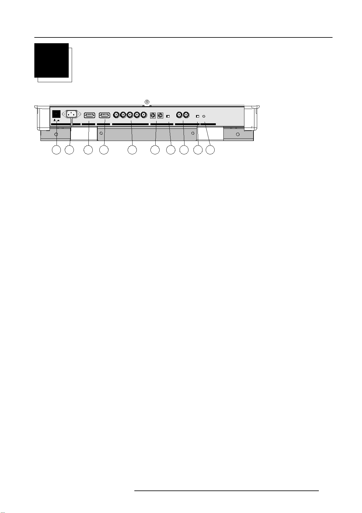
REAR PANEL TERMINOLOGY
green : operation
red : standby
10
This device complies with part 15 of
the FCC rules. Operation is subject to
following two conditions (1). This
device may not cause harmful interference, and (2) this device must
accept any interference received
including interference that may cause
undesired oper ation"
See insta llation i nstructions before connecting to the supply.
Voir la notice d’ in stalla tion avant de ra ccorder au rØseau.
ONOFF
POW ER / MAINS
V-nom
I-nom
Freq
120/230 V
7/5 Amp
50/60 Hz
800 peripherals
COMM. PORT PORT 3
RGB
PORT 4/5
Comp-/H-SyncV-Sync
DEFOCUS OFF - ON
75 Ohm
PORT 2
X-POS Y-POS
PORT 1
OFF - ON
75 Ohm
PROJECTOR MODE
1 2 3 4 5 76 8 9
1 AC Power Switch : to switch on the projector.
Depending on the set-up of the projector during installation, the projector switches to standby or to 'Operational mode. If in standby,
the standby LED lights up.
2 AC Power Input : connect the supplied AC power (mains) cord here and to the wall outlet.
3 Communication Port (800 peripherals)
* Allows communication between the RCVDS switcher and the projector.
* Allows connection of a remote IR receiver unit to the projector.
4 Port 3
RGB Analog Input (9 pin female sub D connector). Allows a character generator, microcomputer, etc. having analog RGB outputs
to be connected to the projector.
5 Port 4/5 : RGB-S Input (5x BNC connector):
RGB-S input : allows a character generator, microcomputer, video camera, etc. having analog RGB output to be connected to the
projector.
Line inputs: - Signals RED-GREEN-BLUE
- COMPOSITE sync. signal
- Tri level sync signal (option)
6 DEFOCUS: For future expansion
7 75 ohm Termination Switch for S- Video signals
8 X-POS / Y-POS: For future expansion
9 75 ohm Termination Switch forVideo signals
10 IR Remote
Connector for remote input for hard wired remote control
11 Projector Pilot Lamp : Indicates the status of the projector.
- Unlit : mains (power) switch is not pressed.
- Lit : mains (power) switch is pressed and the indicated color shows the projector mode:
Green color : operational mode of the projector.
Red color : standby mode of the projector.
Important : projector ("Operational" or "Standby") mode is defined during the installation of the projector. (Refer to a qualified
technician for change).
12 IR Sensor
Receiver for control signals transmitted from the RCU.
13 RS 232 Output Port
RS 232 Input Port allows a communication link for PC or MAC to the next projector in a series of projector.
14 RS 232 Input Port
Connection between the projector and an IBM PC (or compatible) or MAC (RS422) for remote computer control and data communication.
5976283 BARCOGRAPHICS 808s 160403
2-1
Location and Functions of Control
CONTROL PANEL TERMINOLOGY
a. Gaining access to the keyboard
The local keypath is underneath the top cover door with the BARCO logo.
To open this door, push and turn it to the front side of the projector.
This local keypad has the same functions as the Remote Control Unit (RCU).
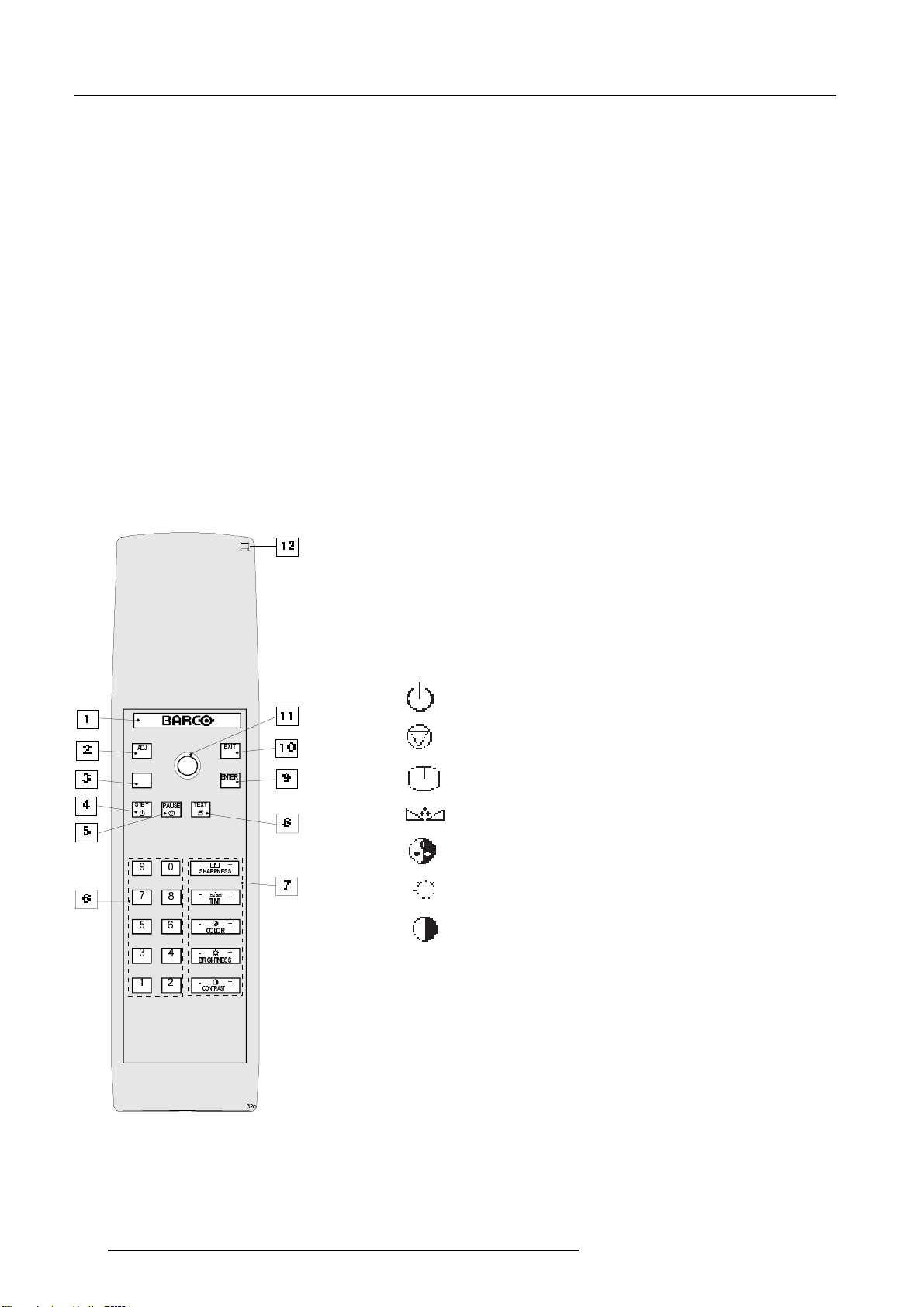
b. RCU control panel
This remote control includes a battery powered infrared (IR) transmitter that allows the user to control the projector remotely.
This remote control is used for source selection, control, adaptation and set-up. It includes automatic storing of :
- Picture controls (Brightness, Sharpness,....)
- Picture geometry adjustments
- Convergence adjustments
Other functions of the remote control are:
- Switching between standby and operational modes
- Switching to "pause" (blanked picture, full power for
immediate restarting)
- Direct access to all connected sources
- Variable adjustment speed : when pushing continuously on the control stick or the picture keys, the adjustment will be
executed in an accelerated fashion.
1 Back light key : When activated, all keys will be lit up and
visible in the dark.
67%<
2 ADJ. : Adjust key, to enter or exit the adjustment mode.
3 Address key (recessed key), to enter the address of the
projector (between 0 and 9). Press the address key,
followed by pressing one digit button between 0 and 9.
4 STBY : Stand by button :
- To initiate remote power up operation
- To stop projection without main power off.
stand-by
$'-
3$86(
(;,7
(17(5
7(; 7
pause/park
sharpness
tint
color
6+$531(66
7,17
&2/25
%5,*+71(66
&2175$67
brightness
contrast
5 Pause : To blank the image, press PAUSE. The image
disappears but full power is retained for immediate restarting.
6 Digit buttons : Direct input selection.
7 Picture controls : Use these buttons to obtain the desired
level (see also 'Controlling') for each picture function.
8 TEXT : When adjusting one of the image controls during a
meeting, the displayed bar scale can be removed by pressing
'TEXT' key first. To re-display the bar scale on the screen,
press 'TEXT' key again. 'TEXT' key is only active in operational
mode. When 'TEXT' is off, no warning message will be
displayed.
11 Control stick key : To make menu selections when in the
adjustment mode. Also allows to increment or decrement an
adjustment in the adjustment mode.
control stick forward = up arrow in the menus
control stick backward = down arrow in the menus
control stick to the right = arrow to the right on the menus
control stick to the left = arrow to the left on the menus
15 RC operating indication : Lights up (green) when a button
on the remote control is pressed. (This is a visual indicator
F
to check the operation of the remote control)
2-2 5976283 BARCOGRAPHICS 808s 160403
Connections
3
CONNECTIONS
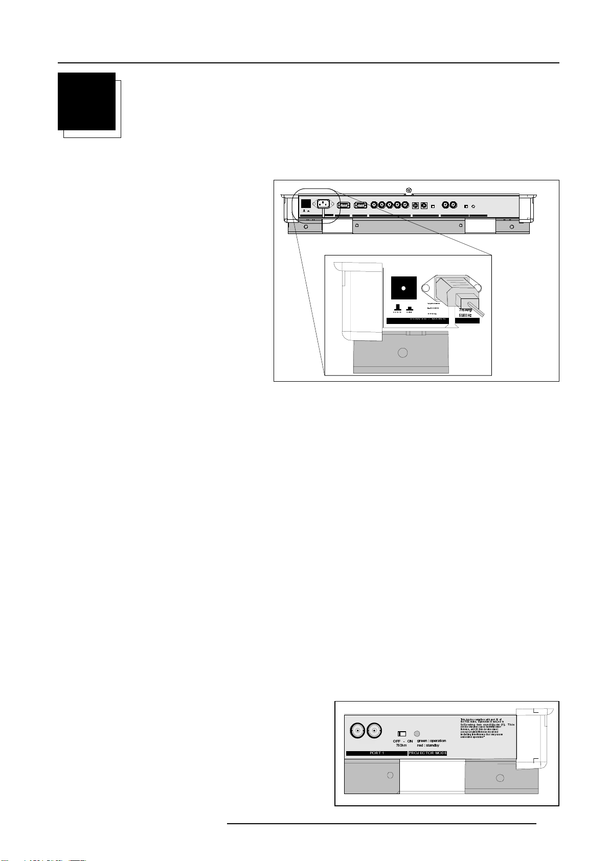
AC Power (mains) Cord Connection
Use the supplied power cord to connect your projector to
the wall outlet. Plug the female power connector into the
male connector on the lower part at the backside of the
projector.
ONOFF
POWE R / MAINS
120/230 V
V-nom
7/5 Amp
I-nom
50/60 Hz
Freq
See ins ta llation i nstructions before connecting to th e supply.
Voir la notice d’in stallation avant de raccorder au rØseau.
800 peripherals
COMM. PORT PORT 3
RGB
PORT 4/5
Comp-/H-SyncV-Sync
2))
DEFOCUS OFF - ON
PORT 2
9QRP
,QRP
21
)UHT
32: (5 0 $,1 6
This device complies with part 15 of
the FCC rules. Operation is subject to
following two conditions (1). This
device may not cause harmful interference, and (2) this device must
accept any interference received
including interference that may cause
undesired operation"
green : operation
OFF - ON
X-POS Y-POS
75 Ohm
PORT 1
75 Ohm
9
$PS
+]
red : standby
PROJECTOR MODE
Power Check
The Power voltage is autoranging between 100V (-10%) and 240V (+6%)
If the wall outlet voltage is different, call a qualified technician for power adaptation of the projector.
Switching On/Off
The projector is switched ON and OFF using the power (mains) switch ON/OFF on the rear panel.
Pressed : ON
Not pressed : OFF
The projector can start in the 'operational mode' (image displayed) or in the 'stand by mode', depending on the position of the 'power up' dip
switch on the controller unit. This DIP switch must be set during installation by a qualified technician. If you want to change this start up
mode, call a qualified technician.
Stand by indication lamp (projector mode) :
No light up : projector switched off
Green color : projector in Operational mode
Red color : projector is in Standby mode.
When starting up the projector, with the power switch or via the stand-by key, the projector can start up in two ways if the "CRT run in"
cycle option is switched OFF.
- full white image (projector warm up) or
- immediate image display.
The way of starting up can be set in the service mode.
9,'(2
3257
2))21
2KP
JUHHQ RSHUD WLRQ
UHGVWDQGE\
352-(&72502'(
7KLVGHYL FHFRPSOLHVZLWKSDUWRI
WKH)&&UXOHV2SHUDWLRQLVVXEMHFWWR
IROORZLQJWZRFRQGLWLRQV7KLV
GHYLFHPD\QRWFDXVHKDUPIXOLQWHU
IHUHQFHDQGWKLVGHYLFHPXVW
DFFHSWDQ\LQWHUIHUHQFHUHFHLYHG
LQFOXGLQJLQWHUIHUHQFHWKDWPD\FDXVH
XQGHVLUH GRSHUD WLRQ
5976283 BARCOGRAPHICS 808s 160403
3-1
Connections
Start up with full white image.
The next menu will be displayed for 30 seconds.
a. Start up with warm up period.
If no action is taken, a white image will be displayed for 20 minutes.
This white image will be shifted on the faceplate of the CRT to avoid a CRT burn in.
During this warm up period, it is possible to interrupt this white image projection by
pressing the EXIT key. The previous menu will be repeated for another 30 seconds
but the remaining time will be indicated.
If EXIT is pressed, the remaining warm up period will be skipped.
During the warm up period, every 30 seconds a text box with the remaining time will
be displayed on the screen for 2 seconds. This text box will be displayed each time
in a different place.
If another key, different from EXIT, is pressed, a text box with following text will be
displayed :
Please use <EXIT> to leave this procedure.
b. Start up without warm up period.
PROJECTOR WARM UP
A FULL WHITE PATTERN
WILL BE GENERATED FOR
20 MINUTES;
FOR INMEDIATE USE OF
THE PROJECTOR, PRESS
<EXIT>;
WARNING : SKIPPING THIS
PROCEDURE CAN REDUCE
THE INITIAL PICTURE
QUALITY OF THE PROJECTED
IMAGE;
THIS OPTION CAN BE
DISABLED IN THE SERVICE
MENU
REMAINING
PROJECTOR
WARM UP
TIME
18.5 MIN
If the EXIT key is pressed, the warm up period will be skipped and the projector is immediately ready for
use.
Warning : skipping this warm up procedure can reduce the initial picture quality of the
projected image.
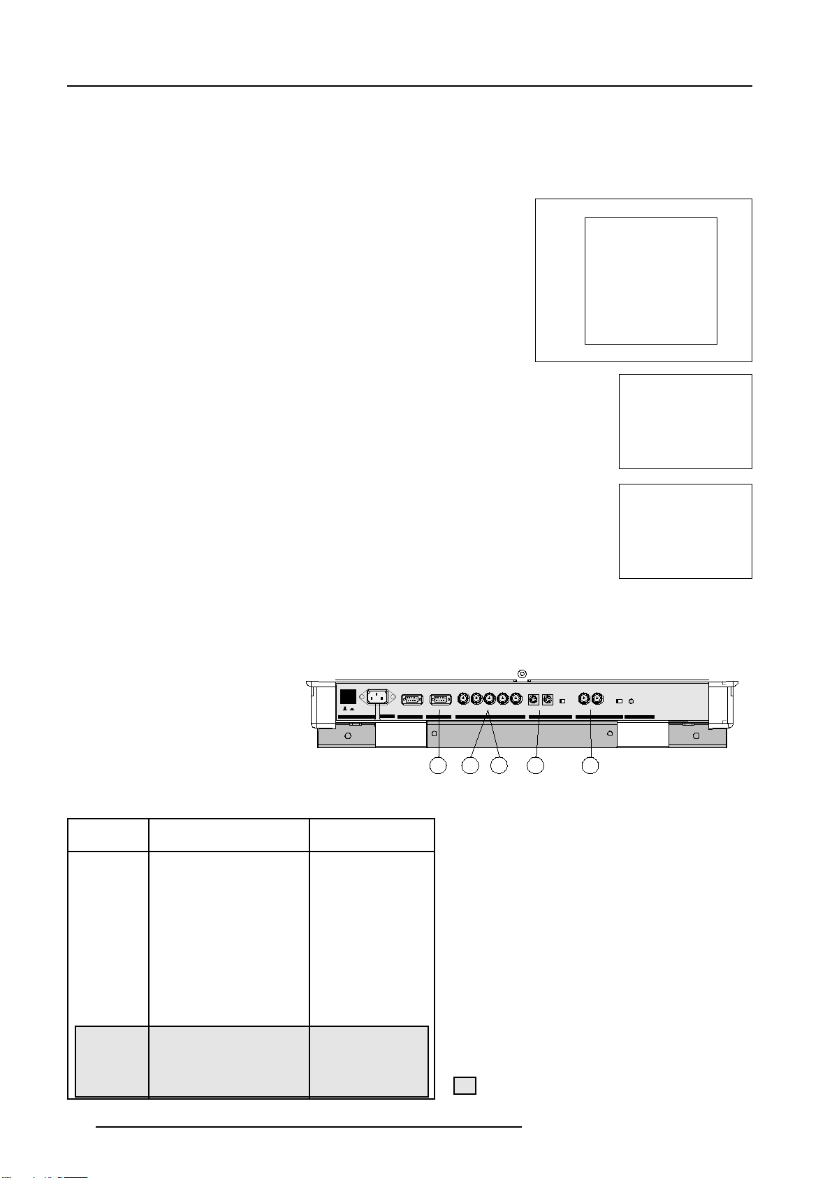
Signal Input Connection to the Projector :
- RGBS or RGsB
- RGB3S or RG3sB (option)
See in stallation instructions before connectin g to th e supply.
Voir la notice d’installa tion avant de raccorder au rØseau.
120/230 V
800 peripherals
V-nom
7/5 Amp
I-nom
50/60 Hz
ONOFF
Freq
POWE R / MAIN S
COMM. PORT PORT 3
Port No Projector input Press Digit Button
1 For future expansion -
2 For future expansion -
3 RGB
4/5 RGB
4/5 Component video
2
2
3
3
4 or 5
6
RGB
PORT 4/5
Comp-/H-SyncV-Sync
DEFOCUS OFF - ON
75 Ohm
PORT 2
5
2
Input signal : R, G and B with automatic sync
detection between seperate sync (separate composite sync or with separate Hor and Vert. sync)
or sync on green (composite sync).
3
Input signal : R-Y, Y and B-Y with separate
composite sync or with separate Hor and Vert.
sync or with composite sync on Y.
4
Input signal : R, G and B with separate Tri level
sync or with Tri-level sync on green.
5
Input signal : R-Y, Y and B-Y with separate Tri
level sync or with composite Tri-level sync.
X-POS Y-POS
123 4
PORT 1
OFF - ON
75 Ohm
green : operation
red : standby
PROJECTOR MODE
PLEASE USE
<EXIT> TO
LEAVE THIS
PROCEDURE
This device complies with part 15 of
the FCC rules. Operation is subject to
following two conditions (1). This
device may not cause harmful interference, and (2) this device must
accept any interference received
including interference that may cause
undesired operati on"
4/5 RGB with Tri level sync
4/5 Component video
with Tri-level sync
4
7
5
8
Only available when the optional Tri-level sync module is installed.
3-2 5976283 BARCOGRAPHICS 808s 160403
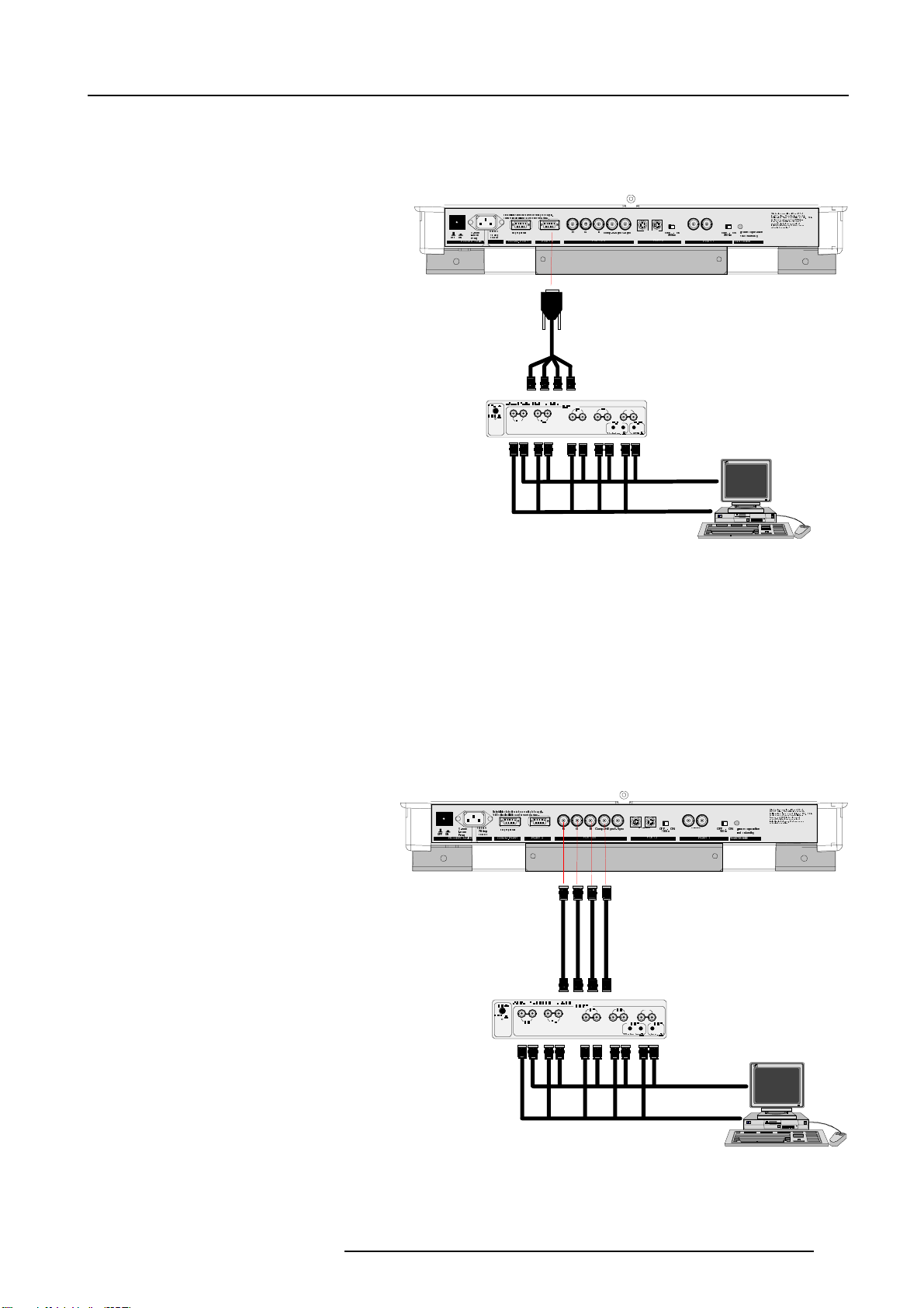
Connecting a RGB Analog source to port 3.
Connect your RGB source via an interface to Port 3.
Always use an interface when a computer and local monitor have
to be connected to the projector.
Connections
Available Barco interfaces :
Universal analog interface R9826100
RGB 120 MHz analog interface R9826570
VGA interface 120V R9828079
230V R9828070
MAC interface 120V R9828059
230V R9828050
MAGIK interface 120V R9828129 & R9828128
230V R9828120 & R9828121
RGB analog input with automatic sync detection. (Separate H and
V sync inputs, with composite sync input or with sync signals on
green)
Pin configuration D9 connector of the Analog input.
1 Not connected
2 Ground RGBS
3 RED
4 GREEN
5 BLUE
6 Ground RGBS
7 Ground RGBS
8 Hor/comp. sync
9 Vert. sync
Analog Input Selection :
Press digit button 3 on the RCU or the local keypad.
Connecting a RGB Analog source to port 4/5.
212))
32:(50$,16
9QRP
,QRP
)UHT
6HHLQVWDOODWLRQLQVWUXFWLRQVEHIRUHFRQQHFWLQJWRWKHVXSSO\
9RLUODQRWLFHGLQVWDOODWLRQDYDQWGHUDFFRUGHUDXUpVHDX
9
$PS
+]
&2003 257 32 57
SHULSKHUDOV
5*%
3257
&RPS+ 6\QF96 \QF
RKPWHUP
LQYHU
69,'(2 2))21
2KP
3257
7KLVGHYLFHFRPSOLHVZLWKSDUWRI
WKH)&&UXOHV2SHUDWLRQLVVXEMHFWWR
IROORZLQJWZRFRQGL WLRQV7KLV
GHYLFHPD\QRWFDXVHKDUPIXOLQWHU
IHUHQFHDQGWKLVGHYLFHPXVW
DFFHSWDQ\LQWHUIHUHQFHUHFHLYHG
LQFOXGLQJLQWHUIHUHQFHWKDWPD\FDXVH
XQGHVLUHGRSHUDWLRQ
JUHHQRSHUDWLRQ
9,'(2
2))21
2KP
UHGVWDQGE\
3257
352-(&72502'(
RGB analog input terminals with separate H and V sync inputs,
composite sync input or sync signals on green (automatic sync
detection).
Always use an interface when a computer and local monitor have
to be connected to the projector. See 'Connecting a RGB Analog
source to port 3' for a list of BARCO interfaces which can be applied.
RGB input selection :
(RGB : R, G, B signals with automatic sync detection)
Press digit button 4 or 5 on the RCU or the local keypad.
212))
32:(50$,1 6
9QRP
,QRP
)UHT
6HHLQVWDOODWLRQLQVWUXFWLRQVEHIRUHFRQQHFWLQJWRWKHVXSSO\
9RLUODQRWLFHGLQVWDOODWLRQDYDQWGHUDFFRUGHUDXUpVHDX
9
$PS
+]
&2003257 3257
SHULSKHUDOV
5*%
3257
&RPS +6\ QF9 6\Q F
RKPWHUP
69,'(2 2))21
2KP
3257
LQYHU
7KLVGHYLFHFRPSOLHVZLWKSDUWRI
WKH)&&UXOHV2SHUDWLRQLVVXEMHFWWR
IROORZLQJWZRFRQGLWLRQV7KLV
GHYLFHPD\QRWFDXVHKDUPIXOLQWHU
IHUHQFHDQGWKLVGHYLFHPXVW
DFFHSWDQ\LQWHUIHUHQFHUHFHLYHG
LQFOXGLQJLQWHUIHUHQFHWKDWPD\FDXVH
XQGHVLUHGRSHUDWLRQ
JUHHQRSHUDWLRQ
2))21
9,'(2
2KP
UHGVWDQGE\
3257
352-(&72502'(
5976283 BARCOGRAPHICS 808s 160403
3-3
Connections
Connecting a RGB Analog source with Tri-level
sync to port 4/5.
(option)
RGB analog input terminals with Tri level sync input or Trilevel sync on green. The projector detects automatically
where the sync signal is located.
RGB input selection :
(RG3sB : R, G, B signals with automatic Tri-level sync detection)
Press digit button 7 on the RCU or the local keypad.
Connecting a Component Video source to
port 4/5.
212))
32:(50$,16
9QRP
,QRP
)UHT
6HHLQVWDOODWLRQLQVWUXFWLRQVEHIRUHFRQQHFWLQJWRWKHVXSSO\
9RLUODQRWLFHGLQVWDOODWLRQDYDQWGHUDFFRUGHUDXUpVHDX
9
$PS
+]
&2003257 3257
SHULSKHUDOV
5*%
3257
&RPS+6\QF96\QF
69,'(2 2))21
2KP
3257
7KLVGHYLFHFRPSOLHVZLWKSDUWRI
WKH)&&UXOHV2SHUDWLRQLVVXEMHFWWR
IROORZLQJWZRFRQGLWLRQV7KLV
GHYLFHPD\QRWFDXVHKDUPIXOLQWHU
IHUHQFHDQGWKLVGHYLFHPXVW
DFFHSWDQ\LQWHUIHUHQFHUHFHLYHG
LQFOXGLQJLQWHUIHUHQFHWKDWPD\FDXVH
XQGHVLUHGRSHUDWLRQ
JUHHQRSHUDWLRQ
9,'(2
2))21
2KP
UHGVWDQGE\
3257
352-(&72502'(
798
A component video (R-Y, Y, B-Y) with sync signals can be connected to the projector via the Port 4/5. The projector automatically
detects where the sync signal is located.
To select the component video input :
Press digit button 6 on the RCU or the local keypad.
Connecting a Component Video source with Trilevel sync to port 4/5.
(Opion)
A component video (R-Y, Y, B-Y) with Tri-level sync signals can be
connected to the projector via the Port 4/5. The projector automatically detects where the sync signal is located.
212))
32:(50$,16
9QRP
,QRP
)UHT
6HHLQVWDOODWLRQLQVWUXFWLRQVEHIRUHFRQQHFWLQJWRWKHVXSSO\
9RLUODQRWLFHGLQVWDOODWLRQDYDQWGHUDFFRUGHUDXUpVHDX
9
$PS
+]
&2003257 3257
SHULSKHUDOV
5*%
3257
&RPS+6\QF96\QF
69,'(2 2))21
2KP
3257
7KLVGHYLFHFRPSOLHVZLWKSDUWRI
WKH)&&UXOHV2SHUDWLRQLVVXEMHFWWR
IROORZLQJWZRFRQGLWLRQV7KLV
GHYLFHPD\QRWFDXVHKDUPIXOLQWHU
IHUHQFHDQGWKLVGHYLFHPXVW
DFFHSWDQ\LQWHUIHUHQFHUHFHLYHG
LQFOXGLQJLQWHUIHUHQFHWKDWPD\FDXVH
XQGHVLUHGRSHUDWLRQ
JUHHQRSHUDWLRQ
9,'(2
2))21
2KP
UHGVWDQGE\
3257
352-(&72502'(
798
7KLVGHYLFHFRPSOLHVZLWKSDUWRI
212))
32:(50$,16
9QRP
,QRP
)UHT
6HHLQVWDOODWLRQLQVWUXFWLRQVEHIRUHFRQQHFWLQJWRWKHVXSSO\
9RLUODQRWLFHGLQVWDOODWLRQDYDQWGHUDFFRUGHUDXUpVHDX
9
$PS
+]
&2003257 3257
SHULSKHUDOV
5*%
3257
&RPS+6\QF96\QF
69,'(2 2))21
2KP
3257
9,'(2
2))21
2KP
3257
352-(&72502'(
JUHHQRSHUDWLRQ
UHGVWDQGE\
WKH)&&UXOHV2SHUDWLRQLVVXEMHFWWR
IROORZLQJWZRFRQGLWLRQV7KLV
GHYLFHPD\QRWFDXVHKDUPIXOLQWHU
IHUHQFHDQGWKLVGHYLFHPXVW
DFFHSWDQ\LQWHUIHUHQFHUHFHLYHG
LQFOXGLQJLQWHUIHUHQFHWKDWPD\FDXVH
XQGHVLUHGRSHUDWLRQ
To select the component video input :
Press digit button 8 on the RCU or the local keypad.
798
3-4 5976283 BARCOGRAPHICS 808s 160403

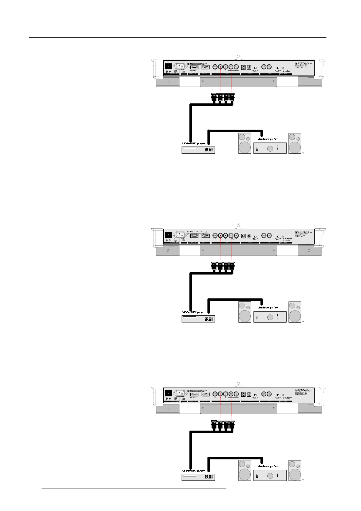
PERIPHERAL EQUIPMENT
Connecting a RCVDS 05 switcher to the
retroprojector.
- Up to 20 inputs with the RCVDS 05 switcher and up to 90 inputs
when 10 RCVDS switchers are linked via the 5-cable input modules.
- Serial communication with the projector.
- Remote control buttons on the RCVDS to control the
retroprojector (source selection and analog settings)
- The selected source number will be displayed on a 2 digit display
and the selected input modules will be indicated with a LED on the
rear.
For more information consult the Owner's Manual of the RCVDS.
Connecting a VS05 switcher to the retroprojector.
The VS05 can switch up to 5 Composite Video sources, 3 S-Video
Sources and 1 RGB analog or component Video source to the
retroprojector. In addition, an audio signal associated with the
source, can be switched to an audio amplifier.
Order number : R9827890.
For more information consult the Owner's Manual.
Connections
Connecting an IR Remote Receiver to the
Projector.
This infrared receiver unit makes it possible to control the projector
from another room. There is a communication line cable between the
IR receiver and the projector or the RCVDS. The infrared control
information from the Remote Control Unit is sent to the IR Remote
Receiver. The IR Remote Receiver 800 displays the selected source
on a 7-segment display.
5976283 BARCOGRAPHICS 808s 160403
3-5

Connections
3-6 5976283 BARCOGRAPHICS 808s 160403
 Loading...