

Cineversum BarcoGraphics 6300 User Manual
BARCO PROJECTION SYSTEMS
Date: 09/02/2000
UNI-TCR
G6300
R9001440/9
ADJUSTMENT MANUAL
Rev:00
Order No. R5976123

Due to constant research, the information in this manual is subject to change without notice.
Produced by BARCO NV, May 1999.
Trademarks are the rights of their respective owners.
All rights reserved.
BARCO n.v./Projection Systems
Noordlaan 5
B-8520 Kuurne
Belgium
Tel.: +32/56/368211
Fax: +32/56/351651
E-mail: sales.bps@barco.com
Visit Barco on the web: http://www.barco.com
Printed in Belgium

GRAPHICS
6300
R9001440/9
Contents Page
Contents
Panel Adjustments ...............................................................................................................5
Recommendation ................................................................................................................................................ 5
Caution ................................................................................................................................................................ 5
Reasons for Adjustment ...................................................................................................................................... 5
Projector settings ................................................................................................................................................. 5
Set Up ................................................................................................................................................................. 5
Starting up the Service Mode ............................................................................................................................... 5
Connection of the TCR tracker unit ..................................................................................................................... 6
Change Baudrate PC .......................................................................................................................................... 6
Change Projector Address................................................................................................................................... 6
Starting the Panel adjustment .............................................................................................................................. 7
Uniformity Adjustment ......................................................................................................... 9
Software Validity .................................................................................................................................................. 9
Reason For Uniformity Correction ....................................................................................................................... 9
Preparation .......................................................................................................................................................... 9
Color Meter........................................................................................................................................................ 10
Line-up of the measurement apparatus ............................................................................................................. 10
RS232 Connection to color meter ...................................................................................................................... 10
Signal connection for Uniformity adjustment ....................................................................................................... 11
Setting Noise Reduction level at 0 ..................................................................................................................... 12
Running the Program ........................................................................................................................................ 12
Step 1 : Input projector data ............................................................................................................................... 12
Automatict Adjustment Procedure: A ................................................................................................................ 14
Manual top-bottom-left-right Adjustment Procedure: M .................................................................................... 16
Overview of Commands .................................................................................................................................... 17
TCR Adjustment ................................................................................................................. 18
Related Item ...................................................................................................................................................... 18
Reason for TCR ................................................................................................................................................ 18
Line-up of the measurement apparatus ............................................................................................................. 19
Color Meter........................................................................................................................................................ 19
Running the Program ........................................................................................................................................ 19
Step 1: Input projector data ................................................................................................................................ 19
Step 2: Green reduction..................................................................................................................................... 22
Step 3: LCD transmission curves....................................................................................................................... 24
Step 4: adj. different color temperatures ............................................................................................................ 26
Step 4: adj. different color temperatures - preset input balance ......................................................................... 26
Automatic Adjustment (Color meter connected!!) ........................................................................................... 29
Manual Adjustment ......................................................................................................................................... 30
Step 5: checking color tracking .......................................................................................................................... 32
Step 7: exit - save settings................................................................................................................................. 33
Important
All described procedures refer to a projector configuration Front/Table
3
Contents
Date: 10/02/2000
GRAPHICS
6300
R9001440/9
Panel Adjustments
NOTES
DATE:__/__/__
Notes
4
Date:10/02/2000
Caution
GRAPHICS
R9001440/9
6300
Panel Adjustments
Panel Adjustment
PANEL ADJUSTMENT TO BE PERFORMED BY
QUALIFIED BARCO PERSONNEL ONLY
The adjustment procedure must be performed with great care. Panel settings
have a dramatic influence on the light output, contrast ratio and color tracking
of the projector.
Reasons for Adjustment
Recommendation
Set Up
Projector settings
Have the adjustment procedure performed after the following occurrences;
1) Replacement of an LCD Panel.
2) Replacement of the LCD Driver Module.
- Before starting any adjustment procedure, first, clean the not replaced panels and
analyzers (see the respective cleaning kit: Art. No R5976057)
- In case of a Software update (see procedure Info T 331), execute first the update
before starting the panel, uniformity and TCR adjustments.
1) The projector must be set up in a table mounted configuration.
2) The room where the procedure is to be performed must be darkened.
Before starting any adjustment procedure, first, set for the projector the Baudrate on
9600 and the address on 001, as follows,
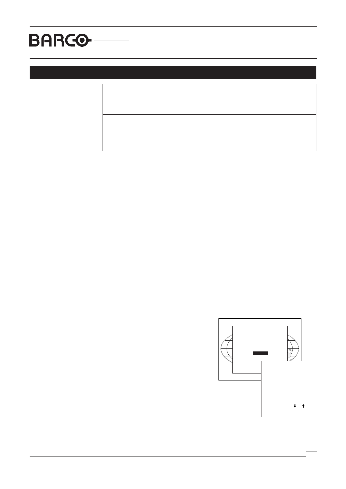
Starting up the Service Mode
Push the cursor key é or ê to highlight
ADJUSTMENT MODE
Select a path from below :
'Service' and then press ENTER.
RANDOM ACCESS
INSTALLATION
Some items in the Service mode are password protected (when the password function
is active). Enter the password to continue.
All other password protected items are now
available if you stay in the adjustment mode.
The service menu is built-up in two parts
which are connected together with the 'more'
item.
If the desired item is not in the list of the
SERVICE
Select with or
then <ENTER>
<EXIT> to return.
SERVICE
IDENTIFICATION
CHANGE PASSWORD
CHANGE LANGUAGE
CHANGE PROJ. ADDRESS
CHANGE BAUDRATE PC
RESET LAMP RUNTIME
LAMP RUNTIME HISTORY
DIMMING
MORE...
Select with or
then <ENTER>
<EXIT> to return.
displayed menu, select 'more' with the cursor key and push ENTER to display the other
items in the service menu.
Panel Adjustments
5
Date:10/02/2000

GRAPHICS
6300
R9001440/9
Panel Adjustments
Change Baudrate PC
The communication speed between projector
and computer, e.g. PC or MAC, has 8 possible
speeds. The baud rate speed can be software
set. Handle as follow:
1 Push the cursor key é or ê to highlight
'Change Baudrate PC''.
2 Press ENTER to display the Change
SERVICE
IDENTIFICATION
CHANGE PASSWORD
CHANGE LANGUAGE
CHANGE PROJ. ADDRESS
CHANGE BAUDRATE PC
RESET LAMP RUNTIME
LAMP RUNTIME HISTORY
DIMMING
MORE...
Select with or
CHANGE BAUDRATE PC
then <ENTER>
<EXIT> to return.
Baudrate PC menu. The actual baudrate
will be highligted.
The following baud rates are available :
230400/115200/57600/38400/19200/9600/
4800/1200
Select with or
<ENTER> to accept
<EXIT> to return.
3 Push the cursor key é or ê to highlight the
baudrate 9600 and press ENTER to select.
Change Projector Address
Every projector requires an individual address
between 0 and 255. This address can be
software installed.
To change that address:
1 Push the cursor key é or ê to highlight
SERVICE
IDENTIFICATION
CHANGE PASSWORD
CHANGE LANGUAGE
CHANGE PROJ. ADDRESS
CHANGE BAUDRATE PC
RESET LAMP RUNTIME
LAMP RUNTIME HISTORY
DIMMING
MORE ...
Select with or
then <ENTER>
CHANGE PROJ. ADDRESS
<EXIT> to return.
Enter new address
'Change Projector Address''.
2 Press ENTER to display the Change
Projector Address menu. The actual
address will be filled in.
Select with or
Reprogram with or
<ENTER> to confirm
Set the projector address on 001 as follows:
The first digit is highlighted. Enter the new projector address with :
- the digit keys on the RCU or the local keypad or
- push the cursor key ç or è to select a digit and change the value by pushing
the cursor key é or ê until the new value is reached. Continue with the other
digits on the same way.
230400
115200
57600
38400
19200
9600
4800
1200
001
or numeric keys
<EXIT> to return
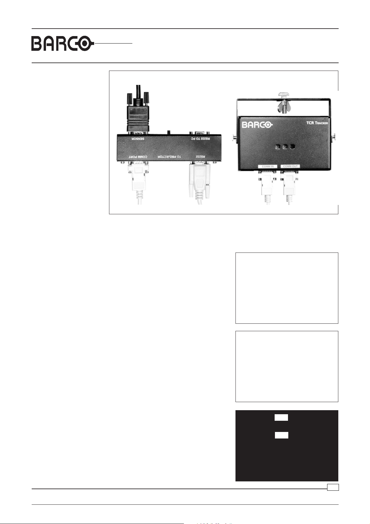
Connection of the TCR
tracker unit
Panel Adjustments
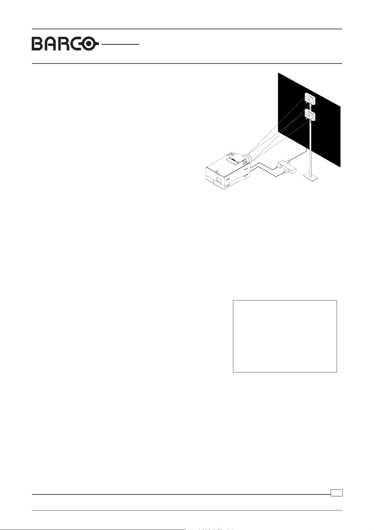
Install the TCR Tracker unit, as illustrated in
drawing below. Make sure that the switch on
the TCR Interface is put in the position OFF
and that the projector is switched to Standby.
Detailed view of the TCR Tracker
and interface, see next page
Projector
TCR Tracker
TCR Interface
to COMM PORT
projector
to RS232 IN
projector
Screen
from Sensor
6
Date:10/02/2000
GRAPHICS
6300
from
Sensors
to COMM PORT
projector
(Order No. CAS LCD TCR R9829970)
ON/OFF
Switch
to RS232 IN
projector
R9001440/9
Contents Page
TCR Tracker Sensor (R763228)TCR Tracker Interface (R763229)
Starting the Panel
adjustment
To start the adjustment procedure, put the ON/OFF switch on the TCR Tracker interface
in the position ON. The MAIN menu will be displayed on the screen.
Selection of item User Guided
MAIN MENU
Push the cursor key é or ê on the RCU or
local key board to highlight 'User Guided'' or
type in number 2 on the numeric keyboard.
1. Automatic
2. User Guided
3. Service
0. EXIT
Press a key
The USER GUIDED menu is displayed on
the screen.
USER GUIDED
1. Panel Settings
2. User Guided
3. Service
4. Save to Default
0. EXIT
Press a key
Panel Adjustments
Selection of item Panel Settings
Push the cursor key é or ê on the RCU or
local key board to highlight 'Panel Settings''
or type in number 1 on the numeric keyboard.
A testpattern, containing two 100% white
rectangles, is generated and projected on
the screen.
Press ENTER to continue
Press EXIT to leave
7
Date: 10/02/2000
GRAPHICS
6300
R9001440/9
Panel Adjustments
Lining up the white rectangles with the
TCR Tracker modules.
Loosen the wing nut on each TCR Tracker
unit and move the unit along the stand until
the two generated white rectangles match
the sensors on the respective TCR Tracker.
When the white rectangles match the respective sensors, Press ENTER on
the local key board or on the RCU to start the panel adjustment procedure.
The automatic panel adjustment process adjusts consecutively the following items:
- Field Flicker adjustment for Red, Green and Blue.
- GAIN adjustment for for Red, Green and Blue.
- Blacklevel adjustment for Red, Green and Blue.
At the end of the adjustment process, duration of about a few minutes, the following
message appears on the screen: SAVE TO DEFAULT. Press ENTER to store the
default values in the projector.
USER GUIDED
1. Panel Settings
2. User Guided
3. Service
4. Save to Default
0. EXIT
Press a key
Panel Adjustments
8
Date:10/02/2000

GRAPHICS
6300
R9001440/9
Uniformity Adjustments
Uniformity Adjustment
Program version
Software Validity
Reason For Uniformity
Correction
Program version 1.02
List of projectors where this adjustment can be used.
Type Art. number
BG6300 TCR+ (DLC)
Soft 1.02 and higher R900144X
BR6300 TCR+ (DLC) R900155X
BG6400 TCR+ (DLC)
BR6400 TCR+ (DLC) R900176X
Color non-uniformities on a LCD projector can have two fundamentally different origins:
- the optical components and
- the LCDs.
An optical non-uniformity is present in the white as well as in the grey as in black and
can be caused by :
- poorly matched mirrors
- vignetting
- birefringence effects in the field lenses, etc
A non-uniformity caused by the LCD becomes more visible in the darker grey and
black levels. It is caused by the fact that the LCD transmission curve is not equal for
the whole LCD area. This can be a result of thickness variations or temperature
variations on the LCD which mainly cause a horizontal shift of the transmission curve.
In this case the effect will be most pronounced for the steepest part of the transmission
curve, this is the mid grey levels.
Other effects, like the stress on the glass induced by the drivers, or the variation of the
average incident angle of the light in different areas of the LCD, have a more complex
influence on the transmission curve, and therefore they are more difficult to
compensate.
With the current compensation program we can compensate the horizontal shift of
the transmission curves on different areas of the screen, so that the first order effect
of thickness and temperature variations can be compensated. As a result the
compensation will give the best results for the grey levels, but will have a very small
effect on the full (projector) white and on the black (there is some effect on e.g. the
6500K white because in that case green is already reduced).
The uniformity compensation can be modified independently on 17x13 points on the
screen. Because it is not feasible to adjust these points one by one, the program
contains an automatic adjustment in which 16 or 25 points are measured and adjusted
with the aid a color meter, and the other points are interpolated.
Preparation The Uniformity Compensation Program requires
- A PC (486, or higher) with 2 COMM ports and DOS.
- The UNI.EXE program.
- A color meter: LMT (C1210 or higher) , Thoma (TMF6 or TMF6 II) or a Minolta
CS1000 color meter.
Uniformity Correction Adjustments
9
Date:10/02/2000
GRAPHICS
6300
R9001440/9
Uniformity Adjustments
- RS232 connection from the PC to the projector and to the color meter. Allow the
projector to warm up during 10 minutes. Put the lamp into the highest power mode.
Close the hoods on the projector. Put the projector in FRONT TABLE configuration.
Darken the room before the evaluation or the measurements start.
For this adjustment the projector white panel settings have to be adjusted properly.
The uniformity adjustment is completely independent from the TCR adjustment, so it
can be done before or after TCR.
Color Meter
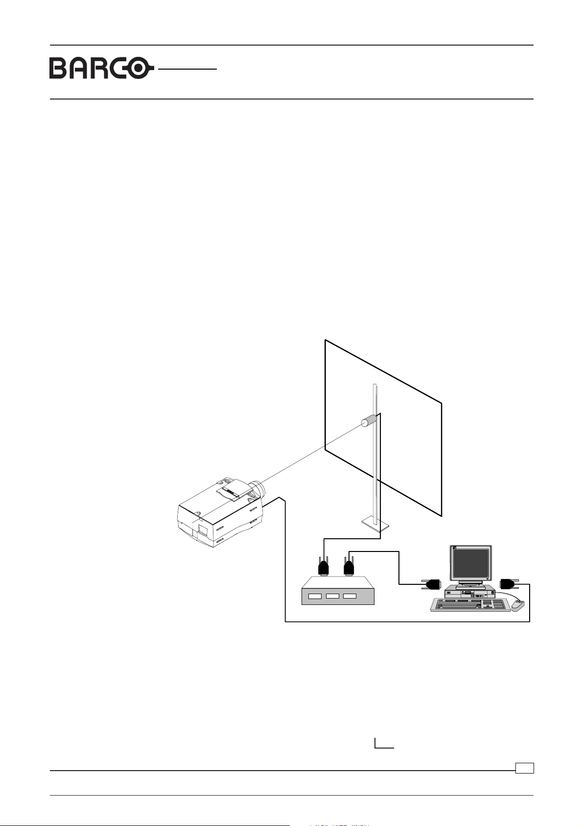
Line-up of the
measurement apparatus
Put the color meter at the center of the image.
In case of the Thoma TMF use a diaphragm to avoid overranging of the meter. In that
case make sure that the light through the diaphragm hits the center spot on the back
of the white integration sphere.
The Minolta CS1000 is used in a reflective measurement mode. Use a perfect white
projection screen. Use the manual measurement mode with an integration time of
0.2s or more.
Check the RS232 to color meter section for the correct RS232 connections to the
color meter.
Screen
Projector
to RS232 IN
projector
RS232 Connection to
color meter
Thoma TMF 6 or TMF 6/II Color Meter
For the RS232 connection between the PC and the Thoma color meter a serial
communication cable with the following connections must be made:
PC PC Thoma
(D9 female connector) (D25 female connector) (D15 male connector)
Pin 2 (RxD) _______________ Pin 3 (RxD) ______________ Pin 3 (DATA OUT)
Pin 3 (TxD) _______________ Pin 2 (TxD) _______________ Pin 2 (DATA IN)
Pin 5 (GND) ______________ Pin 7 (GND) ______________ Pin 1 (MASS)
Uniformity Correction Adjustments
Color meter
PC
to COMM 1
PC
Pin 7 (0 VOLT, DATAGROUND)
from COMM 2
PC
Date:10/02/2000
10

GRAPHICS
6300
R9001440/9
Uniformity Adjustments
LMT C1210I Color Meter
For the RS232 connection between the PC and the LMT C1210 color meter a serial
communication cable with the following connections must be made:
PC PC LMT
(D9 female connector) (D25 female connector) (D25 male connector)
Pin 2 (RxD) __________ Pin 3 (RxD)______________ Pin 3 (TxD)
Pin 3 (TxD) __________ Pin 2 (TxD) ______________ Pin 2 (RxD)
Pin 4 (DTR) __________ Pin 20 (DTR) ____________ Pin 20 (CTS)
Pin 5 (GND)__________ Pin 7 (GND) _____________ Pin 7 (GROUND)
Pin 8 (CTS) __________ Pin 5 (CTS)______________ Pin 5 (RTS)
Minolta CS1000 Color Meter
For the RS232 connection between the PC and the Minolta CS1000 color meter a
serial communication cable with the following connections must be made:
PC PC Minolta CS1000
(D9 female connector) (D25 female connector) (D9 male connector)
Pin 2 (RxD) __________ Pin 2 (TxD) _______________ Pin 3 (TxD)
Pin 3 (TxD) __________ Pin 3 (RxD) _______________ Pin 2 (RxD)
Pin 4 (DTR) __________ Pin 4 (RTS)_______________ Pin 6 (DSR)
Pin 5 (GND)__________ Pin 5 (CTS) _______________ Pin 5 (SG)
Pin 6 (DSR) __________ Pin 6 (DSR) ______________ Pin 4 (DTR)
Pin 7 (RTS) __________ Pin 7 (GND) ______________ Pin 8 (CTS)
Pin 8 (CTS) __________ Pin 20 (DTR) _____________ Pin 7 (RTS)
NOTE: The configurations above do not seem to work in all cases. It is possible that
they will only work if the communication to the Minolta has been initialized by the
accompanying PC-software. The configuration below seems to work without this
initialization:
Minolta alternative configuration:
PC Minolta CS1000
(D9 female connector) (D9 male connector)
Pin 2 (RxD) Pin 3 (TxD)
Pin 3 (TxD) Pin 2 (RxD)
Pin 4 (DTR) Pin 6 (DSR)
Pin 6 (DSR) Pin 4 (DTR)
Pin 5 (GND) Pin 5 (SG)
Pin 7 (RTS) Pin 8 (CTS)
Pin 8 (CTS) Pin 7 (RTS)
Signal connection for
Uniformity adjustment
Connect to the Component Video inputs, the signal Y and the separate Sync signal,
from a reliable multitestpattern generator.
Select on the generator the full white testpattern.
Uniformity Correction Adjustments
11
Date:10/02/2000
 Loading...