

Page 1
5321 DERRY AVENUE, SUITE G
AGOURA HILLS, CALIFORNIA 91301 USA (818) 706-3334 FAX: (818) 706-3335
E-MAIL: info@CinemaElec
com
WEB: www
CinematographyElectronics
com
CINETAPE 2
The Cinematography Electronics CineTape2 is a lightweight and versatile ultrasonic distance measuring
system for any film or digital camera. It provides quick continuous distance measurements and is
compatible with all camera and lens configurations.
The System consists of the CineTape2 Control and the Sensor Horns. A Sensor Cable electrically
connects the CineTape2 to the Sensor Horns, and a Power Cable connects the CineTape2 to the
camera’s accessory connector.
MOUNTING the CONTROL
The solid aluminum case has our standard dovetail-mounting slot along with multiple ¼-20 threaded
attachment holes. The flat back surface of the CineTape2 is also a good area to attach Velcro. These
mounting choices, and the optional Mini Dogbone bracket, provide simple and secure mounting to
cameras, matte-boxes or cheese plates.
MOUNTING the SENSOR HORNS (Sensor Assembly)
The Sensor Horns have an integral pan / tilt head which includes a combo stud for attaching to the
camera or matte-box. The combo stud has a 3/8-16 threaded stud, a ¼-20 threaded hole, and a stepped
shaft with 5/8-inch, 15 mm, and 19 mm diameter steps. These provide numerous attachment
configurations. Attaching the Horns to the camera is preferred, so that the distance to the Focal-Plane
remains constant with lens changes. Always mount the sensors forward of any handles or cables and
pointed towards the subject. (More information is detailed in the “Setting the Focal-Plane offset” area of
these instructions.)
DISTANCE DISPLAY (Numeric Display)
The bright red LED display is located prominently on the front face of the CineTape2. This four-digit
readout shows the measured distance to the subject. The distance is displayed in either Feet or Meters,
and is selectable through the power-up menu. When in the Feet mode, the left two digits indicate “feet”
and the right two digits indicate “inches”. When in the Meters mode, the left two digits indicate “meters”
and the right two digits indicate “centimeters”. Four small squares on the display show that the subject is
out of range. As a reminder, the CineTape2 displays the word “horn" until the Sensor Horns are
connected. The display brightness is adjustable in either the Power-up menu or with the CineTape AIR
App on your iPhone. (More information is detailed in the “Power-up menu” and “CineTape AIR App” areas
of these instructions.)
SENSE LED INDICATOR
The green Sense LED indicator (engraved SENSE) is located on the front face near the right edge. This
green indicator glows when the sensor horns receive a signal from the subject. If the subject is out of
range, the green sense indicator turns off. (More information is detailed in the “Adjusting the Sensitivity”
area of these instructions.)
FOCAL-PLANE LED INDICATOR
The yellow Focal-Plane LED indicator (engraved Push Hold FOCAL-PLANE) is located on the front face
near the right edge. This indicator glows yellow when the CineTape2 is in the Focal-Plane adjustment
mode. (More information is detailed in the “Setting the Focal-Plane offset” area of these instructions.)
4-Sep-19
OPERATING INSTRUCTIONS
CINETAPE 2
.
4 September 2019
.
.
Page 2

OPERATING INSTRUCTIONS
CINETAPE 2
SENSITIVITY LED INDICATOR
The yellow Sensitivity LED indicator (engraved Push SENSITIVITY) is located on the front face near the
right edge. This indicator glows yellow when the CineTape2 is in the Sensitivity adjustment mode. (More
information is detailed in the “Adjusting the Sensitivity” area of these instructions.)
CONNECT LED INDICATOR
The green Connect LED indicator (engraved CONNECT) is located on the front face near the left edge.
This indicator glows green when the CineTape2 is communicating with a wireless AIR Mobile2 on the
same channel.
BT-APP LED INDICATOR (Bluetooth App Indicator)
The blue Bt-App LED indicator (engraved BT-APP) is located on the front face near the left edge. This
indicator glows blue when the CineTape2 is linked via Bluetooth to an iPhone with the CineTape AIR App.
(More information is detailed in the “CineTape AIR App” area of these instructions.)
/ CHANNEL RED PUSH-BUTTON
The red push-button Power/Channel switch (engraved CHANNEL) is located near the top right corner.
This switch has a dual purpose: power on/off and channel selection.
As a power switch, a three (3) second push and hold will turn the CineTape2 off. While off, a single tap
will turn the CineTape2 on.
For wireless channel selection a single tap activates the Channel select mode. The display shows the
current channel, for example “Ch 24”. Rotate the Red Knob on the lower left to choose a new wireless
channel. The CineTape2 has 40 wireless channels to choose from. Save the new channel into memory
by tapping the red channel push-button, which also returns the CineTape2 back to normal operation.
POWER CONNECTOR
The 3 pin Fischer Power connector (engraved POWER) is marked with a red ring and is located on the
bottom edge of the CineTape2. Power connections are through this connector. The required DC voltage
range is 9 to 32 volts. A red cable strain relief identifies power cables that mate to this connector.
Cinematography Electronics offers various power cables. Choose the proper cable for your camera.
REMOTE CONNECTOR
The 4 pin Fischer Remote connector (engraved REMOTE) is marked with a green ring and is located on
the bottom edge of the CineTape2. This connector provides the necessary electrical connections for an
assortment of devices. A green cable strain relief identifies cables that mate to this connector.
Cinematography Electronics has the following cables available:
Adapter - Fischer-4 pin to Lemo-6 pin
Preston MDR ¾ - Fischer-4 to Lemo-4
Arri L-cube (serial) - Fischer-4 to Fischer-7
SENSOR CONNECTOR
The 5 pin Fischer Sensor connector (engraved SENSOR) is marked with a blue ring and is located on the
bottom edge of the CineTape2. This connector provides the necessary electrical connections for the
Sensor Horns. A blue strain relief identifies cables that mate to this connector. The maximum
recommended useable cable length between the CineTape2 and the Sensor Horns is 4 Feet.
Page 2 of 5
Page 3
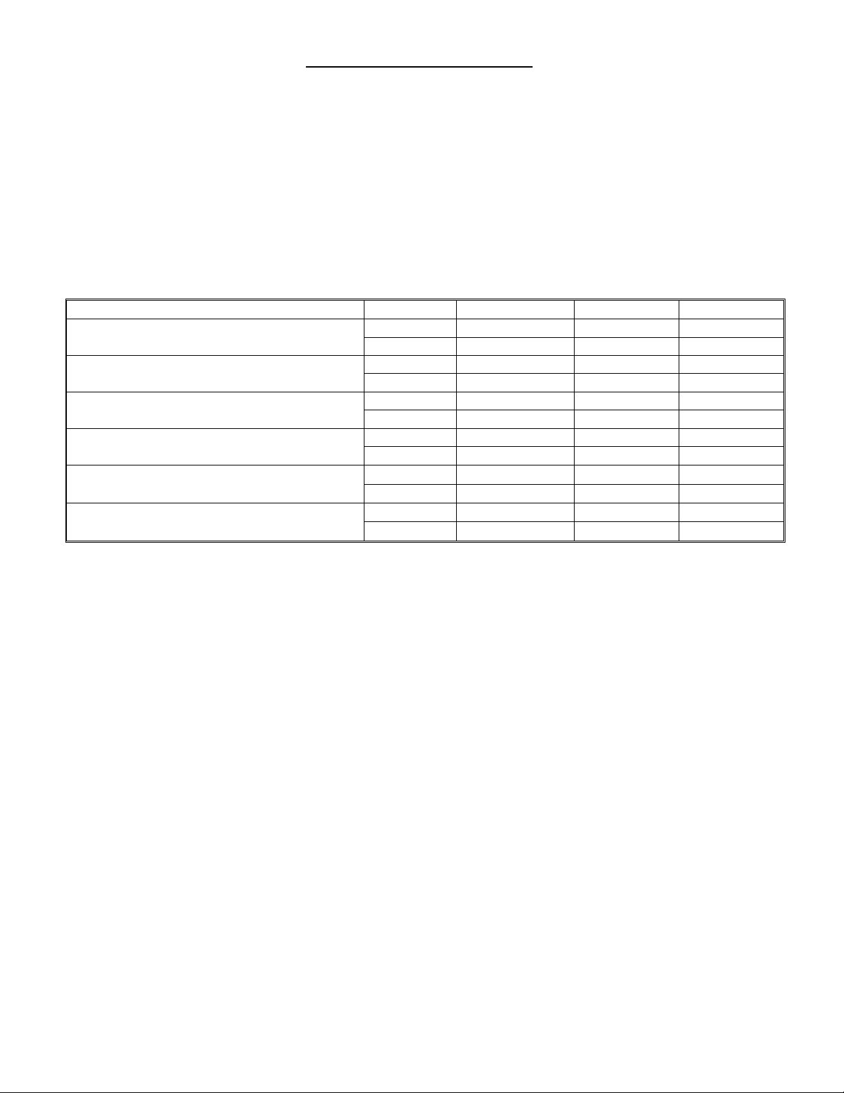
Power-up Menu
PUSH (Click)
PUSH (Hold)
Focal-Plane Offset Adjust
SELECT
X
SET X
Sensitivity Adjust
SELECT X
SET X
Display Brightness Adjust (br)
SELECT X
X
SET X X
Close Focus Distance Adjust (CL)
SELECT X X
SET X X
Display Resolution Adjust (rE)
SELECT X X
SET X X
Feet or Meter Selection (FM)
SELECT X X
SET X X
OPERATING INSTRUCTIONS
CINETAPE 2
SELECT / ADJUST KNOB (Red Knob)
The Red Select / Adjust switch has a large red knob and is located in the lower left corner of the
CineTape2. This multifunctional push and turn switch is the primary method for changing and selecting
the various features of the CineTape2.
Momentarily pushing (click) the Red Knob, or pushing and holding (hold) the Red Knob selects a mode or
saves a selected value. Rotating the Red Knob adjusts the selected function. Clockwise rotation
increases the adjustment and counter clockwise rotation decreases the adjustment.
SETTING the FOCAL-PLANE OFFSET
It is necessary to calibrate the Horns in relation to the focal-plane when setting-up the CineTape2.
To do this, aim the camera package, with the Sensor Horns attached, at a flat stationary object, such as a
wall or clap board, that is about 5 feet (1.5 meters) from the Focal-Plane. With a standard (ordinary) tape
measure, determine the exact distance between the Focal-Plane and the stationary object. Enter the
Focal-Plane adjustment mode, by pushing the Red Knob for two seconds. Release the knob when the
yellow Focal-Plane LED indicator glows. Then rotate the red knob to change the displayed distance
reading to match the, standard tape, measured distance. Save this distance into memory by momentarily
pushing (click) the red knob. This also returns the CineTape2 to normal operation and turns the yellow
Focal-Plane LED indicator off. If the position of the Horns changes with respect to the Focal-Plane, then
recalibration is required.
Page 3 of 5
Page 4

OPERATING INSTRUCTIONS
CINETAPE 2
ADJUSTING the SENSITIVITY
The sensitivity of the CineTape2 is adjustable in 5% steps from 0% (off) to 99% (maximum). Lower
sensitivity settings are useful in small areas that have hard surfaces, such as kitchens or bathrooms. Low
settings are also practical when measuring through doorways or open windows, so that the doorframe
does not affect the sense signal. Higher sensitivity settings are better when the subject is farther away
from the sensors. The reflectivity of the subject is important when setting the sensitivity. For example, a
subject with a fuzzy sweater may absorb more of the signal and therefore require a higher setting. In
addition, the size of the subject, the curvature and angle of the subject are important when selecting the
sensitivity. The green Sense LED indicator is a good guide as to the strength of the signal with respect to
the subject. For best operation, the green Sense LED should glow steadily, without blinking.
To enter the sensitivity adjustment mode, momentarily push (click) the Red Knob. The yellow Sensitivity
LED indicator glows. While the indicator is glowing, rotate the Red Knob to change the sensitivity in 5%
increments. The Distance Display momentarily shows the sensitivity setting as a two-digit number for
about one second as it is changing. The selected setting is saved into memory by pushing (click) the Red
Knob. This also turns the yellow Sensitivity indicator off.
SIGNAL SHAPE & PATTERN
The CineTape2 uses high frequency sound to measure distance. The measurement area is not visible;
therefore, it is important to understand how the shape of the measurement area is controlled by the
sensitivity setting.
The 3-dimensional pattern of the measurement area is similar to an ice cream cone with a scoop of ice
cream. The tip (apex) of the pattern starts at the horns. The diameter of the pattern expands as the
distance increases. As the signal begins to reach its limit the cone shape diameter decreases to form a
round ice cream scoop shape.
Sensitivity settings can be tricky. So, as a guide, with the Sensitivity set at 99%, the diameter of the
pattern, at 10 feet, is 3 feet. This is a large area. To reduce this area, lower the sensitivity setting to 50%.
The diameter of the pattern will be reduced 50%, to roughly 18 inches.
The factory setting for Sensitivity is 70%.
EXTENSION TUBES
Attaching the Cinematography Electronics Extension Tubes to the horns will reduce the overall diameter
of the pattern approximately 20%.
POWER-UP MENU
The Power-up Menu provides settings and adjustments, such as Display Brightness, Close Focus
Distance, Display Resolution and Feet or Meters selection.
The CineTape2 offers two different paths for accessing the Power-up menu. The first method is the same
as the CineTape 1 (original). Simply unplug the power cable, and then plug it back into the CineTape
while pushing and holding the red knob. The second method is new and unique to the CineTape2. Just
turn off the CineTape2 by pushing & holding the power button, then power back on, by tapping the power
button while pushing in and holding the red knob.
Once in the power-up menu, rotate the red knob to the desired setting, then momentarily push (click) to
save the setting into memory. This advances the menu to the next power-up item.
Following is a list of the details for each item in the power-up menu:
Page 4 of 5
Page 5

OPERATING INSTRUCTIONS
CINETAPE 2
Display Brightness Adjustment (br)
Display Brightness is the first item to be accessed through the Power-up Menu and is adjustable in 15
steps. This is useful for comfortable viewing in different lighting conditions. The abbreviation “br” is
used for brightness. The lowest setting is “br 1” and the brightest setting is “br 15”. Adjust the
brightness to the desired level by turning the Red knob. The display shows the new brightness setting
and varies as it is adjusted. The new setting is saved into memory by momentarily pushing (click) the
red knob, which also advances the Power-up Menu to the Close Focus Distance Adjust.
The CineTape Air App also has a Display Brightness. Available at the Apple iTunes store.
Close Focus Distance Adjustment (CL) Near Limit
The Close Focus Distance is the second item accessed through the Power-up Menu. The Close Focus
Distance is also known as the Near Limit and is the minimum distance that the CineTape2 senses.
The abbreviation “CL” is used for close. It is adjustable in 15 steps from “CL 7” to “CL 21”,
corresponding to about 1 foot (30 cm) to 3 feet (90 cm), respectively. This is a useful setting when it is
necessary to ignore something in the foreground near the sensors, such as a Matte Box, French flag,
monitor or cable. Adjust the near limit close focus to the desired distance by rotating the Red knob.
The new setting is saved into memory by momentarily pushing (click) the red knob, which also
advances the Power-up Menu to the Display Resolution Adjustment.
Display Resolution Adjustment (rE)
The Display Resolution is the third item accessed through the Power-up Menu. The Display Resolution
is the amount of distance rounding-off that is shown on the CineTape2 display. Reducing the
resolution (Increasing the rounding-off) is useful when a more stable display is desired. The resolution
setting is the third item accessed through the Power-up Menu. This setting shows as “rE x” or “rE –x”
where “rE” is the abbreviation for resolution and “x” is the amount of rounding-off. The displayed minus
sign (-) is the graphical representation for plus or minus (+/-). The four resolution settings are; 1, 2, -1
& -2.
• The ‘1’ setting is the normal (maximum) setting and maintains the displayed distance until the
actual (physical) distance change is greater than 1 unit. (This is the factory setting)
• The ‘2’ setting maintains the displayed distance until the actual (physical) distance change is
greater than 2 units. Only even numbers are displayed.
• The ‘-- 1’ setting maintains the displayed distance until the actual (physical) distance change is
plus or minus (+/-) 1 unit.
• The ‘-- 2’ setting maintains the displayed distance until the actual (physical) distance change is
plus or minus (+/-) 2 units. Only even numbers are displayed.
Adjust the Display Resolution to the desired level by rotating the Red knob. The new setting is saved
into memory by momentarily pushing (click) the red knob, which also advances the Power-up Menu to
the Feet/Meters Selection.
Feet or Meters Selection (FM)
The Feet/Meter selection is 4th item in the Power-Up Menu. Rotate the red knob and select ‘F’ for Feet
or M for Meters. All of the distance readings and focus-plane calculations convert automatically to the
selected units. When in the Feet mode, the left two digits indicate “feet” and the right two digits
indicate “inches”. When in the Meters mode, the left two digits indicate “meters” and the right two digits
indicate “centimeters”. The new setting is saved into memory by momentarily pushing (click) the Red
knob, which closes the Power-up Menu.
Page 5 of 5
 Loading...