

Page 1
Page 2

DE-1000
Power Efficient Fanless Computer
| User’s Manual
2
Contents
Prefaces
Revision …………………………………………………..……………….……….. 04
Copyright Notice …………………………………………………………………… 04
Acknowledgement ……………………………………………………................... 04
Disclaimer ………………………………………………………….……………….. 04
Declaration of Conformity ……………………………………….………………… 04
Product Warranty Statement ……………………………………….…………….. 05
Technical Support and Assistance ………………………………….……………. 06
Conventions Used in this Manual …………………………………….………….. 06
Safety Precaution …..…………………………………….…………….………….. 07
Package Contents ……………………………………………….……….………… 08
Ordering Information …………………………………………….……….………… 09
Optional Accessory …………...……………………………………...................... 10
Chapter 1 Product Introductions
1.1 Overview ……………………………………………………………….. 12
1.1.1 Key Feature …………………………………..……………....... 12
1.2 Hardware Specification ………………………………..……………… 13
1.3 System I/O ……………………………………………………………… 14
1.3.1 DE-1000 …………………………………………………….…… 14
1.3.2 DE-1000(L/P) ……………………………………………….…… 16
1.3.3 DE-1001 …………………………………………………….…… 18
1.3.4 DE-1001(L/P) ……………………………………………….…… 20
1.3.5 DE-1002 …………………………………………………….…… 22
1.3.6 DE-1002(L/P) ……………………………………………….…… 24
1.4 Mechanical Dimension …………………………………..……………. 26
1.4.1 DE-1000 …………………………………………………….…… 26
1.4.2 DE-1000(L/P) ……………………………………………….…… 27
1.4.3 DE-1001 …………………………………………………….…… 28
1.4.4 DE-1001(L/P) ……………………………………………….…… 29
1.4.5 DE-1002 …………………………………………………….…… 30
1.4.6 DE-1002(L/P) ……………………………………………….…… 31
Chapter 2 Jumpers and Connectors
2.1 Jumper Settings ……………………………………………………..... 33
2.2 Locations of the Jumper and Connector ………………………….... 33
2.2.1 Top View ………………………………………………………… 33
2.2.2 Bottom View …………………………………………………….. 34
2.3 Connector / Jumper / Switch Definition …………….…….………..... 35
2.4 Switch Definition …………….……………........................................ 36
2.5 Jumper Definition …………………………........................................ 37
2.6 Connector Definition …………………………................................... 38
Chapter 3 System Setup
3.1 Removing the Chassis Bottom Cover ……...………………………... 50
3.2 Removing the Chassis …………………….…..…….……………….... 51
3.3 Installing a Half Size Mini PCIe Card on Upper Side .…………….... 52
3.4 Installing a Full Size Mini PCIe Card on Upper Side ….………….... 55
3.5 Installing Antenna …………………………………..….…………….... 57
Page 3

DE-1000
Power Efficient Fanless Computer
| User’s Manual
3
3.6 Installing a SATA Hard Drive on Upper Side ……..….…………….... 59
3.7 Installing a SATA Hard Drive on Bottom Side ……..….……..…….... 61
3.8 Installing SO-DIMM 1 …..….……………………………….……….... 62
3.9 Installing SO-DIMM 2 …..….……………………………….……….... 64
3.10 Installing a Half Size Mini PCIe Card on Bottom Side …..…….….... 66
3.11 Installing a Full Size Mini PCIe Card on Bottom Side …..………...... 69
3.12 Installing the PCI/PCIe Cards on Expansion Module …..………...... 72
3.13 Installing the Chassis ………….…………..………..….…………….... 75
3.14 Installing the Chassis Bottom Cover …..…………..….…………….... 76
3.15 Installing a SIM Card ………….……………..….…..….…………….... 77
3.16 Installing a CFast Card ……...………………….…..….…………….... 78
3.17 Wall Mount Bracket ..……….……………….….…..….…………….... 79
Chapter 4 BIOS Setup
4.1 BIOS Introduction …….……….…………….…….…..….…………... 82
4.2 Main Setup ……..……….………………….…..….………………...... 83
4.2.1 System Date …….…………………………………………….... 83
4.2.2 System Time ………..…………………………………………... 83
4.3 Advanced Setup ……………………………………………………….. 84
4.3.1 ACPI Settings ……..……………………………………………. 84
4.3.2 Super IO Configuration ………………………………………... 85
4.3.3 Hardware Monitor …………………………………………….... 89
4.3.4 Serial Port Console Redirection ……………..……………..... 89
4.3.5 CPU Configuration ……………………………..………….….... 90
4.3.6 PPM Configuration ..…………………………..……………..... 91
4.3.7 Thermal Configuration ……..………………………………..... 92
4.3.8 IDE Configuration …………………………………………….... 93
4.3.9 OS Selection ……………….………………………………….... 94
4.3.10 CSM (Compatibility Support Module) Configuration ………. 95
4.3.11 USB Configuration …………………………………………….. 96
4.4 Chipset …………...……….………………….…..….…..……………... 97
4.4.1 North Bridge ………….………………………………………….. 97
4.4.2 South Bridge ………….………………………………………….. 99
4.5 Security …………...……….………………….…..….…..……………... 101
4.5.1 Administrators Password …….………………………………….. 101
4.5.2 Users Password …….……………………………………,,…….. 101
4.6 Boot …………...……….….………………….…..….…..……………... 102
4.6.1 Setup Prompt Timeout ………………………………………….. 102
4.6.2 Bootup NumLock State …………………………………………. 102
4.6.3 Full Screen Logo Show …………………………………………. 102
4.6.4 Fast Boot …………………………………………………………. 102
4.7 Save & Exit …...……….….………………….…..….…..…………….... 103
4.7.1 Save Changes and Reset ……………..……………………...... 103
4.7.2 Discard Changes and Reset …………………………………….103
4.7.3 Restore Defaults …………………………………………………. 103
4.7.4 Save as User Defaults …………………………………………… 103
4.7.5 Restore User Defaults …………………………………………… 103
Page 4
DE-1000
Power Efficient Fanless Computer
| User’s Manual
4
Revision
Copyright Notice
© 2014 by Cincoze Co., Ltd. All rights are reserved. No parts of this manual may be copied, modified,
or reproduced in any form or by any means for commercial use without the prior written permission of
Cincoze Co., Ltd. All information and specification provided in this manual are for reference only and
remain subject to change without prior notice.
Acknowledgement
Cincoze is a registered trademark of Cincoze Co., Ltd. All registered trademarks and product names
mentioned herein are used for identification purposes only and may be trademarks and/or registered
trademarks of their respective owners.
Disclaimer
This manual is intended to be used as a practical and informative guide only and is subject to change
without notice. It does not represent a commitment on the part of Cincoze. This product might include
unintentional technical or typographical errors. Changes are periodically made to the information
herein to correct such errors, and these changes are incorporated into new editions of the publication.
Declaration of Conformity
Prefaces
FCC
This equipment has been tested and found to comply with the limits for a Class A digital
device, pursuant to Part 15 of the FCC Rules. These limits are designed to provide
reasonable protection against harmful interference when the equipment is operated in a
commercial environment. This equipment generates, uses, and can radiate radio
frequency energy and, if not installed and used in accordance with the instruction
manual, may cause harmful interference to radio communications. Operation of this
equipment in a residential area is likely to cause harmful interference in which case the
user will be required to correct the interference at his own expense.
CE
The product(s) described in this manual complies with all application European Union
(CE) directives if it has a CE marking. For computer systems to remain CE compliant,
only CE-compliant parts may be used. Maintaining CE compliance also requires proper
cable and cabling techniques.
Revision
Description
Date
1.0 Manual Released
2015/01/12
Prefaces
Page 5

DE-1000
Power Efficient Fanless Computer
| User’s Manual
5
Product Warranty Statement
Warranty
Cincoze products are warranted by Cincoze Co., Ltd. to be free from defect in materials and
workmanship for 2 years from the date of purchase by the original purchaser.
During the warranty period, we shall, at our option, either repair or replace any product that proves to
be defective under normal operation.
Defects, malfunctions, or failures of the warranted product caused by damage resulting from natural
disasters (such as by lightening, flood, earthquake, etc.), environmental and atmospheric disturbances,
other external forces such as power line disturbances, plugging the board in under power, or incorrect
cabling, and damage caused by misuse, abuse, and unauthorized alteration or repair, and the product
in question is either software, or an expendable item (such as a fuse, battery, etc.), are not warranted.
RMA
Before sending your product in, you will need to fill in Cincoze RMA Request Form and obtain a RMA
number from us. Our staff is available at any time to provide you with the most friendly and immediate
service.
RMA Instruction
Customers must fill in Cincoze Return Merchandise Authorization (RMA) Request Form and
obtain a RMA number prior to returning a defective product to Cincoze for service.
Customers must collect all the information about the problems encountered and note anything
abnormal and describe the problems on the “Cincoze Service Form” for the RMA number apply
process.
Charges may be incurred for certain repairs. Cincoze will charge for repairs to products whose
warranty period has expired. Cincoze will also charge for repairs to products if the damage
resulted from acts of God, environmental or atmospheric disturbances, or other external forces
through misuse, abuse, or unauthorized alteration or repair. If charges will be incurred for a
repair, Cincoze lists all charges, and will wait for customer’s approval before performing the
repair.
Customers agree to insure the product or assume the risk of loss or damage during transit, to
prepay shipping charges, and to use the original shipping container or equivalent.
Customers can be send back the faulty products with or without accessories (manuals, cable,
etc.) and any components from the system. If the components were suspected as part of the
problems, please note clearly which components are included. Otherwise, Cincoze is not
responsible for the devices/parts.
Repaired items will be shipped along with a "Repair Report" detailing the findings and actions
taken.
Limitation of Liability
Cincoze’ liability arising out of the manufacture, sale, or supplying of the product and its use, whether
based on warranty, contract, negligence, product liability, or otherwise, shall not exceed the original
selling price of the product. The remedies provided herein are the customer’s sole and exclusive
remedies. In no event shall Cincoze be liable for direct, indirect, special or consequential damages
whether based on contract of any other legal theory.
Prefaces
Page 6
DE-1000
Power Efficient Fanless Computer
| User’s Manual
6
Technical Support and Assistance
1. Visit the Cincoze website at www.cincoze.com/support.php where you can find the latest
information about the product.
2. Contact your distributor or our technical support team or sales representative for technical support
if you need additional assistance. Please have following information ready before you call:
Product name and serial number
Description of your peripheral attachments
Description of your software (operating system, version, application software, etc.)
A complete description of the problem
The exact wording of any error messages
Conventions Used in this Manual
Prefaces
This indication alerts operators to an operation that, if not strictly
observed, may result in severe injury.
WARNING
This indication alerts operators to an operation that, if not strictly
observed, may result in safety hazards to personnel or damage to
equipment.
CAUTION
This indication provides additional information to complete a task easily.
NOTE
Page 7

DE-1000
Power Efficient Fanless Computer
| User’s Manual
7
Safety Precautions
Before installing and using this device, please note the following precautions:
1. Read these safety instructions carefully.
2. Keep this User’s Manual for future reference.
3. Disconnected this equipment from any AC outlet before cleaning.
4. For plug-in equipment, the power outlet socket must be located near the equipment and must be
easily accessible.
5. Keep this equipment away from humidity.
6. Put this equipment on a reliable surface during installation. Dropping it or letting it fall may cause
damage.
7. Make sure the voltage of the power source is correct before connecting the equipment to the
power outlet.
8. Use a power cord that has been approved for using with the product and that it matches the
voltage and current marked on the product’s electrical range label. The voltage and current rating
of the cord must be greater than the voltage and current rating marked on the product.
9. Position the power cord so that people cannot step on it. Do not place anything over the power
cord.
10.All cautions and warnings on the equipment should be noted.
11.If the equipment is not used for a long time, disconnect it from the power source to avoid damage
by transient overvoltage.
12.Never pour any liquid into an opening. This may cause fire or electrical shock.
13.Never open the equipment. For safety reasons, the equipment should be opened only by qualified
service personnel.
If one of the following situations arises, get the equipment checked by service personnel:
The power cord or plug is damaged.
Liquid has penetrated into the equipment.
The equipment has been exposed to moisture.
The equipment does not work well, or you cannot get it to work according to the user's manual.
The equipment has been dropped and damaged.
The equipment has obvious signs of breakage.
14. CAUTION: Danger of explosion if battery is incorrectly replaced. Replace only with the same or
equivalent type recommended by the manufacturer.
Prefaces
Page 8

DE-1000
Power Efficient Fanless Computer
| User’s Manual
8
Package Contents
Before installation, please ensure all the items listed in the following table are included in the package.
Item Description Q’ty
1 DE-1000(L/P) / DE-1001(L/P) / DE-1002(L/P) Embedded System 1
2 Utility DVD Driver 1
3 DIO Terminal Block Connector (Female) 2
4 Power Terminal Block Connector (Female) 1
5 Remote Power Terminal Block Connector (Female) 2
6 DVI-I to VGA Adapter 1
7 Screw Pack 1
8 Wall Mount Kit 1
Note: Notify your sales representative if any of the above items are missing or damaged.
Prefaces
Page 9

DE-1000
Power Efficient Fanless Computer
| User’s Manual
9
Ordering Information
Prefaces
Model No. Product Description
DE-1000
Intel® Atom™ E3845 Quad Core Power Efficient Fanless Computer
DE-1000L
Intel® Atom™ E3845 Quad Core Power Efficient Fanless Computer, 6x LAN
DE-1000P
Intel® Atom™ E3845 Quad Core Power Efficient Fanless Computer, 4x PoE and 2x LAN
DE-1001-E
Intel® Atom™ E3845 Quad Core Power Efficient Fanless Computer, 1x PCIe x1 Expansion
DE-1001-P
Intel® Atom™ E3845 Quad Core Power Efficient Fanless Computer, 1x PCI Expansion
DE-1001L-E
Intel® Atom™ E3845 Quad Core Power Efficient Fanless Computer, 1x PCIe x1 Expansion and 6x
LAN
DE-1001L-P
Intel® Atom™ E3845 Quad Core Power Efficient Fanless Computer, 1x PCI Expansion and 6x
LAN
DE-1001P-E
Intel® Atom™ E3845 Quad Core Power Efficient Fanless Computer, 1x PCIe x1 Expansion, 4x
PoE and 2x LAN
DE-1001P-P
Intel® Atom™ E3845 Quad Core Power Efficient Fanless Computer, 1x PCI Expansion, 4x PoE
and 2x LAN
DE-1002-EE
Intel® Atom™ E3845 Quad Core Power Efficient Fanless Computer, 2x PCIe x1 Expansion
DE-1002-PP
Intel® Atom™ E3845 Quad Core Power Efficient Fanless Computer, 2x PCI Expansion
DE-1002L-EE
Intel® Atom™ E3845 Quad Core Power Efficient Fanless Computer, 2x PCIe x1 Expansion and 6x
LAN
DE-1002L-PP
Intel® Atom™ E3845 Quad Core Power Efficient Fanless Computer, 2x PCI Expansion and 6x
LAN
DE-1002P-EE
Intel® Atom™ E3845 Quad Core Power Efficient Fanless Computer and 2x PCIe x1 Expansion, 4x
PoE and 2x LAN
DE-1002P-PP
Intel® Atom™ E3845 Quad Core Power Efficient Fanless Computer and 2x PCI Expansion, 4x
PoE and 2x LAN
Page 10

DE-1000
Power Efficient Fanless Computer
| User’s Manual
10
Optional Accessories
Model Name
Description
GSM60A12
-CIN
Adapter AC/DC 12V 5A 60W with 3pin Terminal Block Plug 5.0mm Pitch,
GS60MA12-P1J
GS120A24-CIN
Adapter AC/DC 24V 5A 120W with 3pin Terminal Block Plug 5.0mm Pitch,
GS120A24-P1M
SL2-SL3
US 2 heads power cord, US B type to IEC C13, SVT 18AWG/3C Black 1.8M
SL-2+SL-3
SL6
-SL3
EU 2 heads power cord, EU G type to IEC C13,H05VV-F 0.75mm2/3G Black
1.8M SL-6+SL-3
QP026
-SL3
UK 2 heads power cord, UK I type to IEC C13, H05VV-F 0.75mm2/3G Black
1.8M QP026+SL-3
VESA
-DE
DE series VESA Mount Kit
SIDE
-DE
DE series SIDE Mount Kit
DINRAIL
Diamond series DIN-RAIL Mount Kit
59381560000E
MINI-DIN(M) (PS/2 KB+MS) TO MINI-DIN(F) (PS/2 KB)+MINI-DIN(F) (PS/2
MS) L:10CM, 59381560000E
N0307
-140507-01
DVI-I(M) TO DVI-D(F) + VGA(F) Cable, L=200mm, N0307-140507-01
Prefaces
Page 11

Product Introductions
Chapter 1
Page 12
DE-1000
Power Efficient Fanless Computer
| User’s Manual
12
1.1.1 Key Features
• Onboard Intel® Atom™ E3845 Processor Quad Core, 1.91GHz
• 2x DDR3L SO-DIMM Max. up to 8GB
• Dual Independent Display from 1x DVI-I and 1x DisplayPort
• 2x Intel® GbE Port, Support Wake-on-LAN and PXE (DE-1000, DE-1001, DE-1002 Only)
• 6x Intel® GbE Port, Support Wake-on-LAN and PXE (DE-1000L, DE-1001L, DE-1002L Only)
• 6x Intel® GbE Port with 4x PoE Function, Support Wake-on-LAN, 2x Support PXE (DE-1000P,
DE-1001P, DE-1002P Only)
• 1x USB 3.0, 4x USB 2.0
• 6x RS232/422/485 Port with 5V/12V Power
• 4x Isolated DI, 4x Isolated DO
• 2x 2.5” SATA SSD/HDD Bay, 1x mSATA (Shared by Mini-PCIe Socket) , 1x CFast Card
and 1x SIM Card Socket
• 9~48VDC Power Input, support AT/ATX Mode
• 2x Mini-PCIe Slot for Wi-Fi, GSM, or I/O Expansion
• 1x PCI or 1x PCIe x1 Expansion (DE-1001, DE-1001L, DE-1001P Only)
• 2x PCI or 2x PCIe x1 Expansion (DE-1002, DE-1002L, DE-1002P Only)
• Power Ignition
• Compliant with EN50155 for Rail Transportation Applications
1.1 Overview
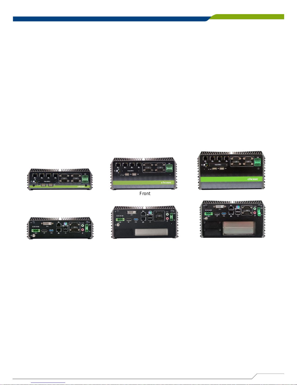
DE-1000 Series Fanless Embedded PC supports Intel® Bay Trail platform, integrated with Intel®
Atom™ E3845 Quad Core 1.91 GHz processor. Delivering the excellent quad-core processing power
at only 10 watts power consumption, DE-1000 series is definitely an ideal solution for ultimate
computing performance, energy efficiency, and superior reliability.
Designed with rich I/O, high flexibility and easy expansion capabilities, DE-1000 series is ideal for
diverse industrial applications. It offers multiple I/O extension modules, including up to 2x PCI or 2x
PCIe x1 slot for flexible integration of a variety of add-on cards; 2x mini-PCIe slot for GSM and WLAN
wireless communication; it also supports three storage expansions: 2.5” SATA HDD, CFast and SIM
card.
Supporting up to 6x LAN or 4x POE versions, and power ignition function, DE-1000 series can meet
various applications, such as: surveillance, in-vehicle, and industrial automation applications, etc.
DE-1000 series supports wide temperature range from -20°C to +70°C, wide range (9~48V) DC power
input, power protection, cable free and one-piece housing design, as well as compliant with EN50155
certification for rail transportation applications; it is designed to ensure stable operation in robust and
harsh environments.
Chapter 1: Product Introductions
Rear
Front
DE-1000(L/P)
Rear
Front
DE-1001(L/P) DE-1002(L/P)
Rear
Front
Page 13

DE-1000
Power Efficient Fanless Computer
| User’s Manual
13
Processor System
• Onboard Intel® Atom™ Processor E3845 Quad
Core, 1.91 GHz with AMI 64Mbit SPI BIOS
Memory
• 2x 204-Pin DDR3L-1066 / 1333MHz SO-DIMM
(un-buffered and non-ECC), Max. up to 8GB
Display
Dual Display
• 1x DVI and 1x DisplayPort
• 1x DVI-D and 1x VGA (w/ Optional Split Cable)
• 1x DisplayPort and 1x VGA (w/ DVI-I to VGA
Adapter)
Expansion
• DE-1001-E, DE-1001L-E, DE-1001P-E
1x PCIe x1
• DE-1001-P, DE-1001L-P, DE-1001P-P
1x PCI
• DE-1002-EE, DE-1002L-EE, DE-1002P-EE:
2x PCIe x1
• DE-1002-PP, DE-1002L-PP, DE-1002P-PP
2x PCI
• 2x Full-size Mini PCIe Socket for Wi-Fi / GSM /
Expansion Module
• 1x Universal I/O Bracket (DE-1001, DE-1001L,
DE-1001P Only)
• 2x Universal I/O Bracket (DE-1002, DE-1002L,
DE-1002P Only)
Ethernet
• 2x Intel® i210-AT GbE LAN Port, Support Wake-onLAN and PXE
• 4x Intel® 82583V GbE LAN Port, Support Wake-onLAN (DE-1000L/P, DE-1001L/P, DE-1002L/P Only)
• 4x 802.3af Compliant PoE Port, The Maximum DC
Power Delivery on Each PoE is 25W@DC 56V Input
(DE-1000P, DE-1001P, DE-1002P Only)
Audio
• Codec: Realtek ALC888S
• 1x Mic-in and 1x Speak-out
Watchdog Timer
• Software Programmable Supports 1~255 sec.
System Reset
Storage
• 2x 2.5” SATA HDD Bay
• 1x Internal mSATA Slot (Shared by Mini-PCIe
Socket)
• 1x External CFast Socket
• 1x External SIM Card Socket
I/O Ports
• 1x USB 3.0 Port
• 4x USB 2.0 Port
• 1x 4 Isolated DI & 4 Isolated DO Port
• 6x DB9 for COM1~6, Support RS232/422/485 with
Auto Flow Control
• 1x PS/2 Port
• 2x Antenna Hole
• 1x Power Switch
• 1x AT/ATX Switch
• 1x Remote Power and Reset Connector
Digital Input & Output
• 4x Digital Input (Source Type)
- Input Voltage (Dry Contact):
Logic 0: Close to GND
Logic 1: Open
- Input Voltage:
Logic 0: 3V max.
Logic 1: 5V min. (DI to COM-)
• 4x Digital Output
- Supply Voltage: 5~30VDC
- Sink Current: 200 mA Max. Per Channel
Power
• Support AT, ATX Mode
• 1x 3-pin Terminal Block Connector with Power Input
9~48VDC
• 1x Optional AC/DC 12V/5A, 60W Power Adapter
• 1x Optional AC/DC 24V/5A, 120W Power Adapter
(DE-1000P, DE-1001P, DE-1002P Only)
Environment
• Operating Temperature: Ambient with Air Flow:
-20°C to 70°C (with Industrial Grade Peripherals)
• Storage Temperature: -30°C to 85°C
• Relative humidity: 10%~95% (non-condensing)
Physical
• DE-1000(L/P)
Dimension (WxDxH, mm): 203 x 200 x 65 mm
Weight: 2.84 kg
• DE-1001(L/P)
Dimension (WxDxH, mm): 203 x 200 x 96.5 mm
Weight: TBD
• DE-1002(L/P)
Dimension (WxDxH, mm): 203 x 200 x 114.5 mm
Weight: 3.66 kg
• Construction: Extruded Aluminum with Heavy Duty
Metal
• Mounting: Wall Mounting (Side / VESA / DIN-Rail
For DE-1000(L/P) Only)
Operating System
• Windows® 8
• Windows® Embedded 8 Standard
• Windows® 7
• Windows® Embedded Standard 7
Certifications
• CE
• FCC Class A
• EN 50155
• EN 50121-3-2
Chapter 1: Product Introductions
1.2 Hardware Specification
Page 14
DE-1000
Power Efficient Fanless Computer
| User’s Manual
14
Chapter 1: Product Introductions
1.3 System I/O
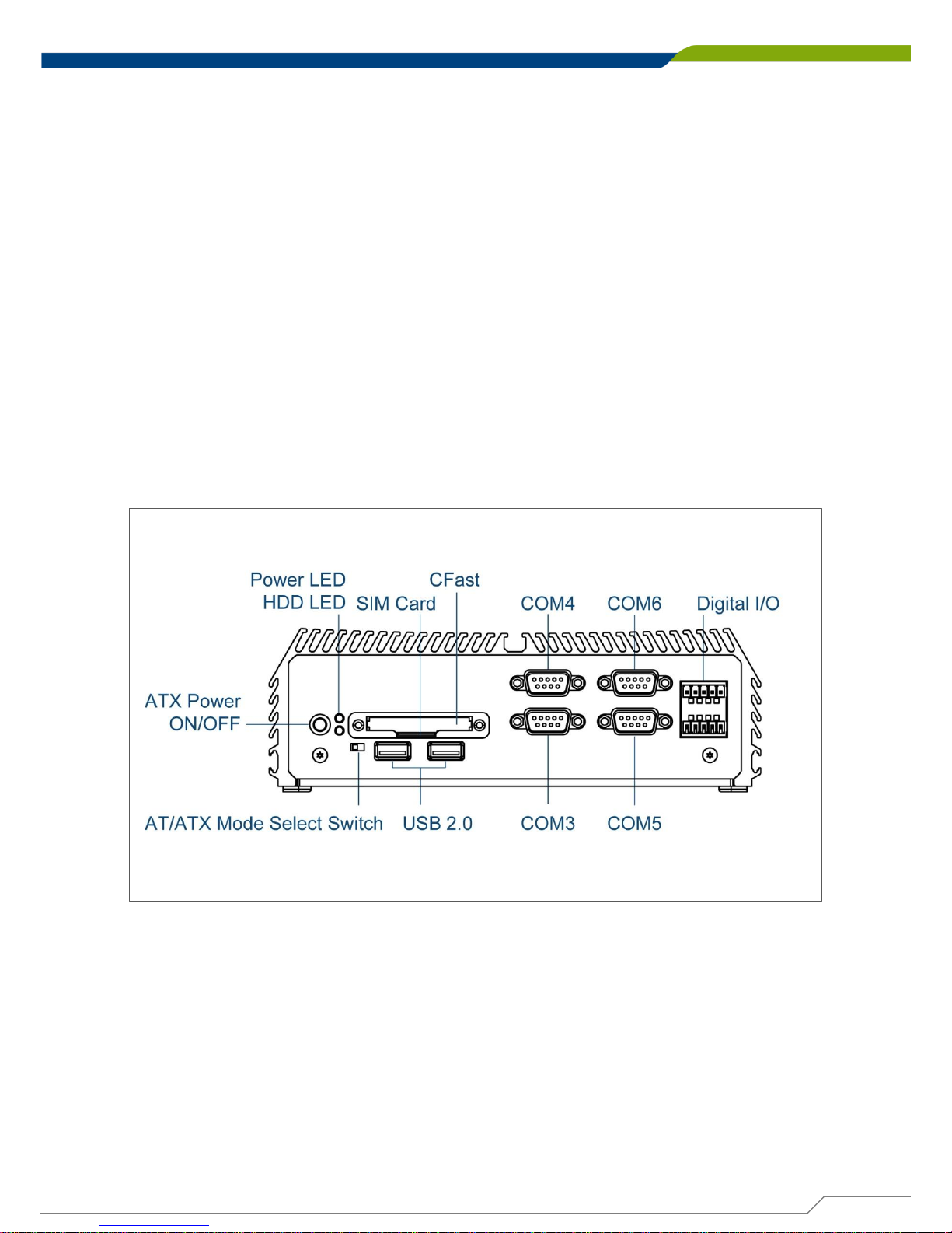
1.3.1 DE-1000
Front Panel
ATX power on/off switch
Press to power-on or power-off the system
Power LED
Indicates the power status of the system
HDD LED
Indicates the status of the hard drive
USB 2.0 port
Used to connect USB 2.0/1.1 device
AT/ATX mode select switch
Used to select AT or ATX power mode
CFast and SIM card
Used to insert a CFast card and SIM card
COM port
COM 3 ~ COM6 support RS232/422/485 serial device
Digital I/O Terminal Block
The Digital I/O terminal block supports 4 digital input
and 4 digital output
Page 15
DE-1000
Power Efficient Fanless Computer
| User’s Manual
15
Chapter 1: Product Introductions
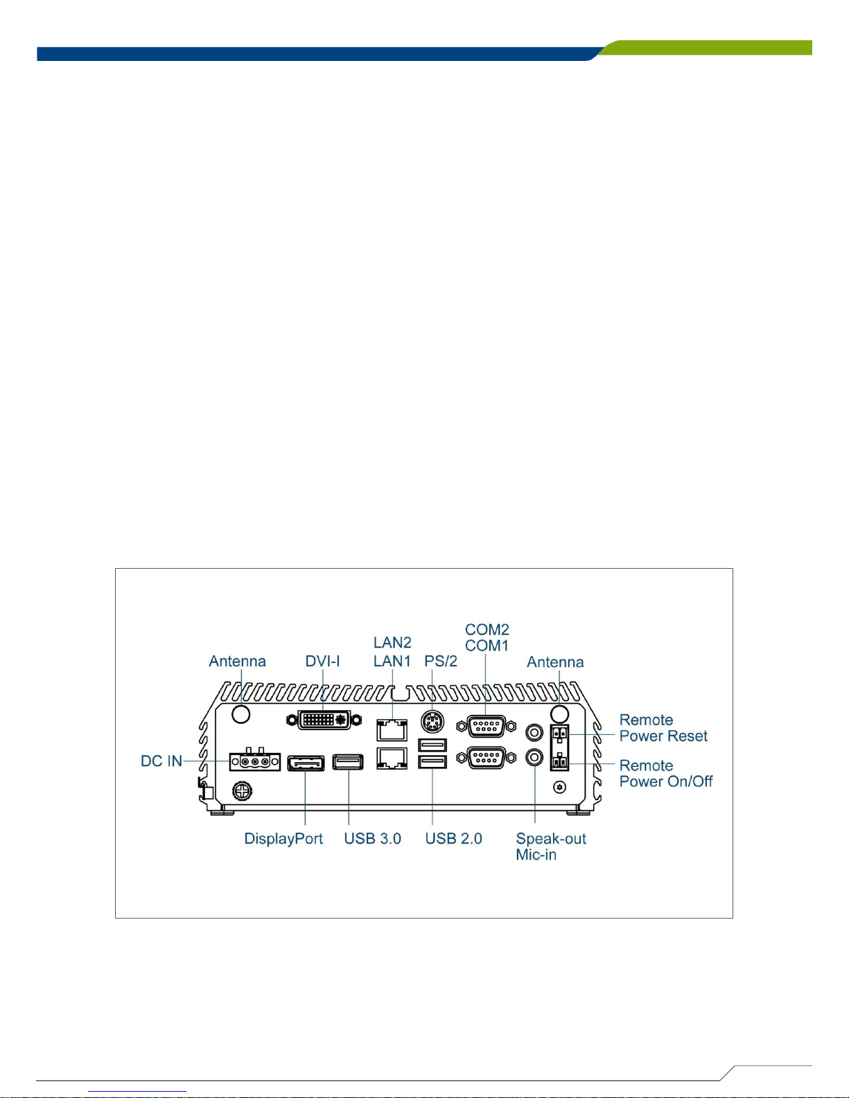
Rear Panel
DC IN
Used to plug a DC power input with terminal block
DVI-I port
Used to connect a DVI monitor or connect optional
split cable for dual display mode
PS/2 Port
Used to connect the PS/2 device
LAN port
Used to connect the system to a local area network
USB 3.0 port
Used to connect USB 3.0/2.0/1.1 device
USB 2.0 port
Used to connect USB 2.0/1.1 device
DisplayPort
Used to connect a DisplayPort monitor
Antenna hole
Used to connect an antenna for optional Mini-PCIe
WiFi module
COM port
COM 1 ~ COM 2 support RS232/422/485 serial device
Mic-in
Used to connect a microphone
Speaker-out
Used to connect a speaker
Remote Power on/off and Remote Power
Reset Terminal Block
Used to plug a remote power on/off and remote power
reset with terminal block
Universal I/O Bracket
Used to customized I/O output
Page 16
DE-1000
Power Efficient Fanless Computer
| User’s Manual
16
Chapter 1: Product Introductions
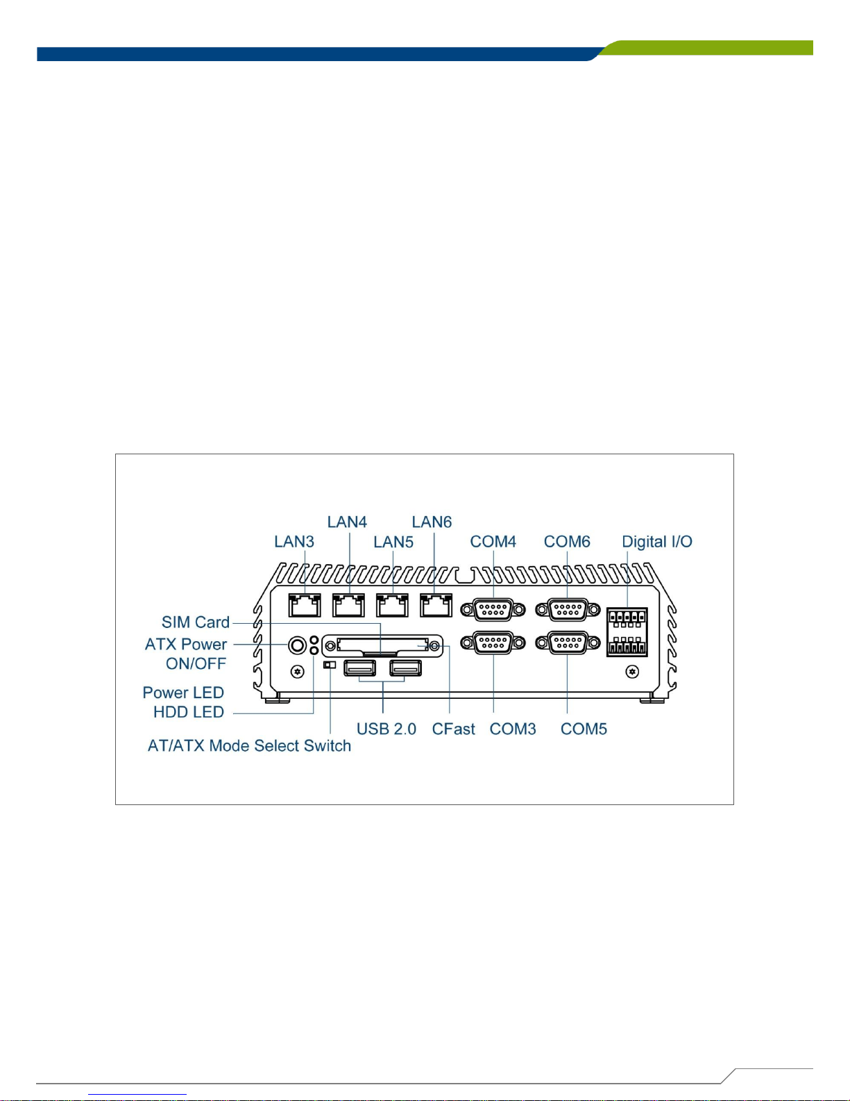
1.3.2 DE-1000(L/P)
Front Panel
ATX power on/off switch
Press to power-on or power-off the system
Power LED
Indicates the power status of the system
HDD LED
Indicates the status of the hard drive
USB 2.0 port
Used to connect USB 2.0/1.1 device
AT/ATX mode select switch
Used to select AT or ATX power mode
CFast and SIM card
Used to insert a CFast card and SIM card
COM port
COM 3 ~ COM6 support RS232/422/485 serial device
Digital I/O Terminal Block
The Digital I/O terminal block supports 4 digital input
and 4 digital output
Page 17
DE-1000
Power Efficient Fanless Computer
| User’s Manual
17
Chapter 1: Product Introductions
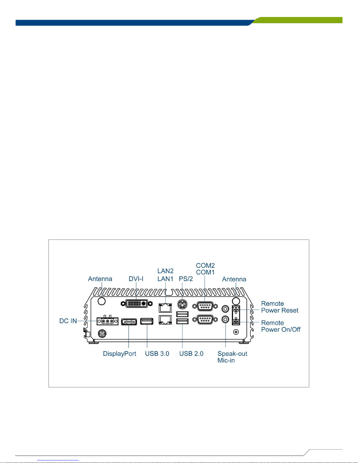
Rear Panel
DC IN
Used to plug a DC power input with terminal block
DVI-I port
Used to connect a DVI monitor or connect optional
split cable for dual display mode
PS/2 Port
Used to connect the PS/2 device
LAN port
Used to connect the system to a local area network
USB 3.0 port
Used to connect USB 3.0/2.0/1.1 device
USB 2.0 port
Used to connect USB 2.0/1.1 device
DisplayPort
Used to connect a DisplayPort monitor
Antenna hole
Used to connect an antenna for optional Mini-PCIe
WiFi module
COM port
COM 1 ~ COM 2 support RS232/422/485 serial device
Mic-in
Used to connect a microphone
Speaker-out
Used to connect a speaker
Remote Power on/off and Remote Power
Reset Terminal Block
Used to plug a remote power on/off and remote power
reset with terminal block
Universal I/O Bracket
Used to customized I/O output
Page 18
DE-1000
Power Efficient Fanless Computer
| User’s Manual
18
Chapter 1: Product Introductions
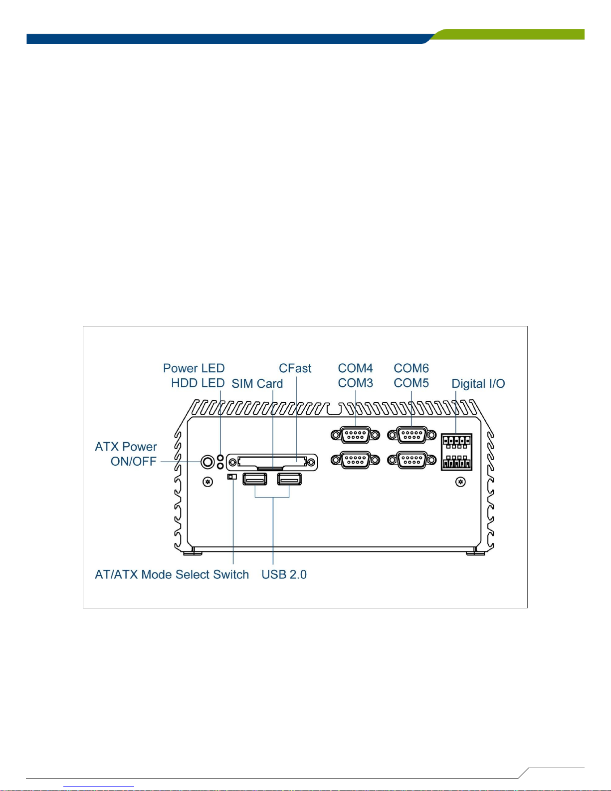
1.3.3 DE-1001
Front Panel
ATX power on/off switch
Press to power-on or power-off the system
Power LED
Indicates the power status of the system
HDD LED
Indicates the status of the hard drive
USB 2.0 port
Used to connect USB 2.0/1.1 device
AT/ATX mode select switch
Used to select AT or ATX power mode
CFast and SIM card
Used to insert a CFast card and SIM card
COM port
COM 3 ~ COM6 support RS232/422/485 serial device
Digital I/O Terminal Block
The Digital I/O terminal block supports 4 digital input
and 4 digital output
Page 19
DE-1000
Power Efficient Fanless Computer
| User’s Manual
19
Chapter 1: Product Introductions
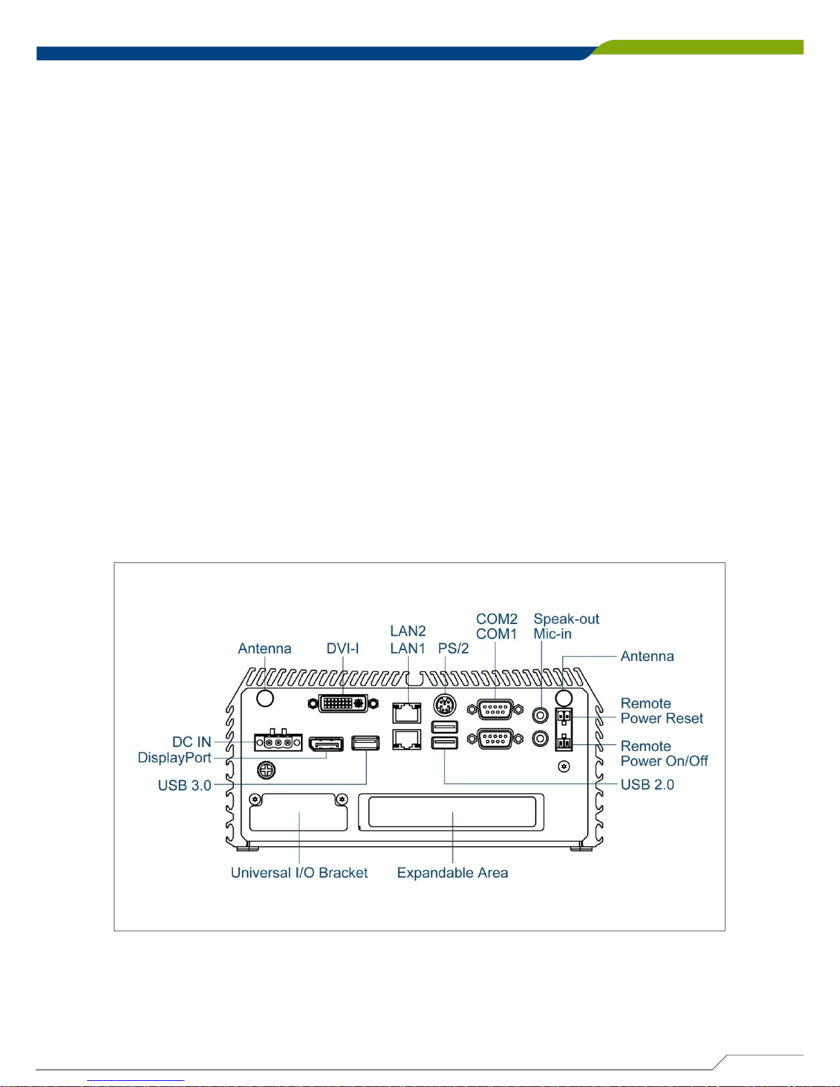
Rear Panel
DC IN
Used to plug a DC power input with terminal block
DVI-I port
Used to connect a DVI monitor or connect optional
split cable for dual display mode
PS/2 Port
Used to connect the PS/2 device
LAN port
Used to connect the system to a local area network
USB 3.0 port
Used to connect USB 3.0/2.0/1.1 device
USB 2.0 port
Used to connect USB 2.0/1.1 device
DisplayPort
Used to connect a DisplayPort monitor
Antenna hole
Used to connect an antenna for optional Mini-PCIe
WiFi module
COM port
COM 1 ~ COM 2 support RS232/422/485 serial device
Mic-in
Used to connect a microphone
Speaker-out
Used to connect a speaker
Remote Power on/off and Remote Power
Reset Terminal Block
Used to plug a remote power on/off and remote power
reset with terminal block
Universal I/O Bracket
Used to customized I/O output
Page 20
DE-1000
Power Efficient Fanless Computer
| User’s Manual
20
Chapter 1: Product Introductions
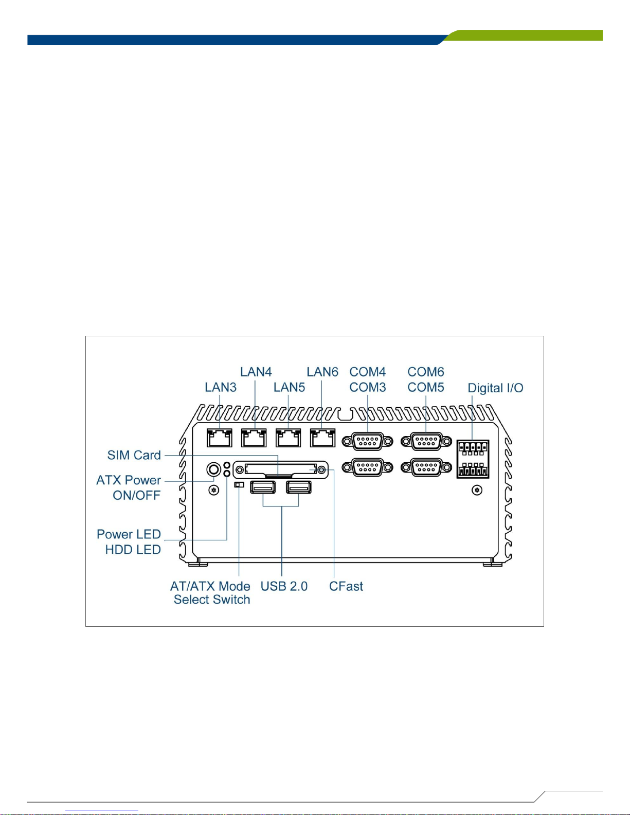
1.3.4 DE-1001(L/P)
Front Panel
ATX power on/off switch
Press to power-on or power-off the system
Power LED
Indicates the power status of the system
HDD LED
Indicates the status of the hard drive
USB 2.0 port
Used to connect USB 2.0/1.1 device
AT/ATX mode select switch
Used to select AT or ATX power mode
CFast and SIM card
Used to insert a CFast card and SIM card
COM port
COM 3 ~ COM6 support RS232/422/485 serial device
Digital I/O Terminal Block
The Digital I/O terminal block supports 4 digital input
and 4 digital output
Page 21
DE-1000
Power Efficient Fanless Computer
| User’s Manual
21
Chapter 1: Product Introductions
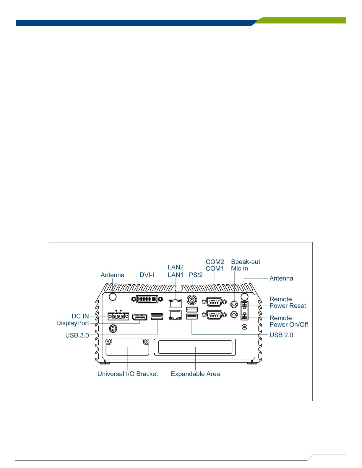
Rear Panel
DC IN
Used to plug a DC power input with terminal block
DVI-I port
Used to connect a DVI monitor or connect optional
split cable for dual display mode
PS/2 Port
Used to connect the PS/2 device
LAN port
Used to connect the system to a local area network
USB 3.0 port
Used to connect USB 3.0/2.0/1.1 device
USB 2.0 port
Used to connect USB 2.0/1.1 device
DisplayPort
Used to connect a DisplayPort monitor
Antenna hole
Used to connect an antenna for optional Mini-PCIe
WiFi module
COM port
COM 1 ~ COM 2 support RS232/422/485 serial device
Mic-in
Used to connect a microphone
Speaker-out
Used to connect a speaker
Remote Power on/off and Remote Power
Reset Terminal Block
Used to plug a remote power on/off and remote power
reset with terminal block
Universal I/O Bracket
Used to customized I/O output
Page 22
DE-1000
Power Efficient Fanless Computer
| User’s Manual
22
Chapter 1: Product Introductions
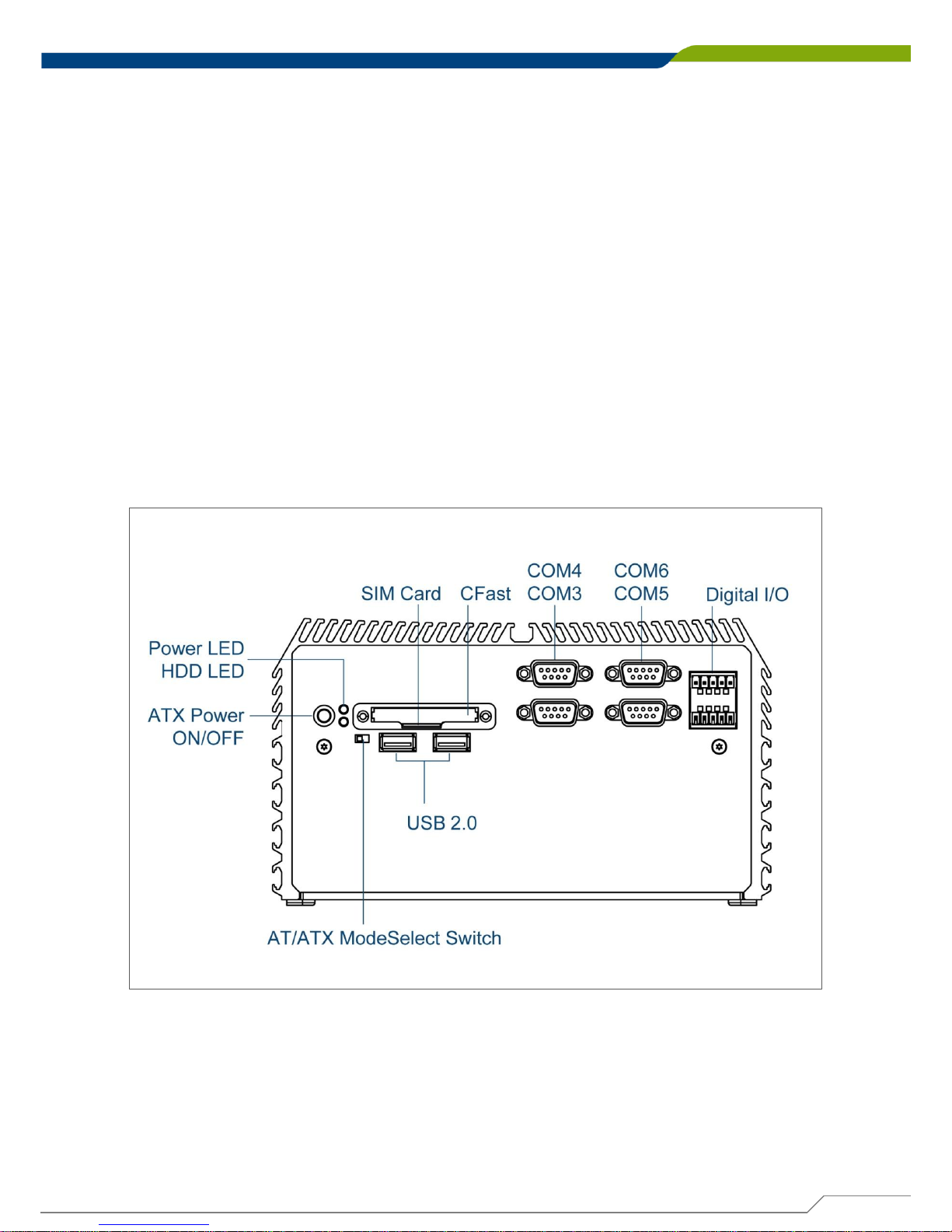
1.3.5 DE-1002
Front Panel
ATX power on/off switch
Press to power-on or power-off the system
Power LED
Indicates the power status of the system
HDD LED
Indicates the status of the hard drive
USB 2.0 port
Used to connect USB 2.0/1.1 device
AT/ATX mode select switch
Used to select AT or ATX power mode
CFast and SIM card
Used to insert a CFast card and SIM card
COM port
COM 3 ~ COM6 support RS232/422/485 serial device
Digital I/O Terminal Block
The Digital I/O terminal block supports 4 digital input
and 4 digital output
Page 23
DE-1000
Power Efficient Fanless Computer
| User’s Manual
23
Chapter 1: Product Introductions
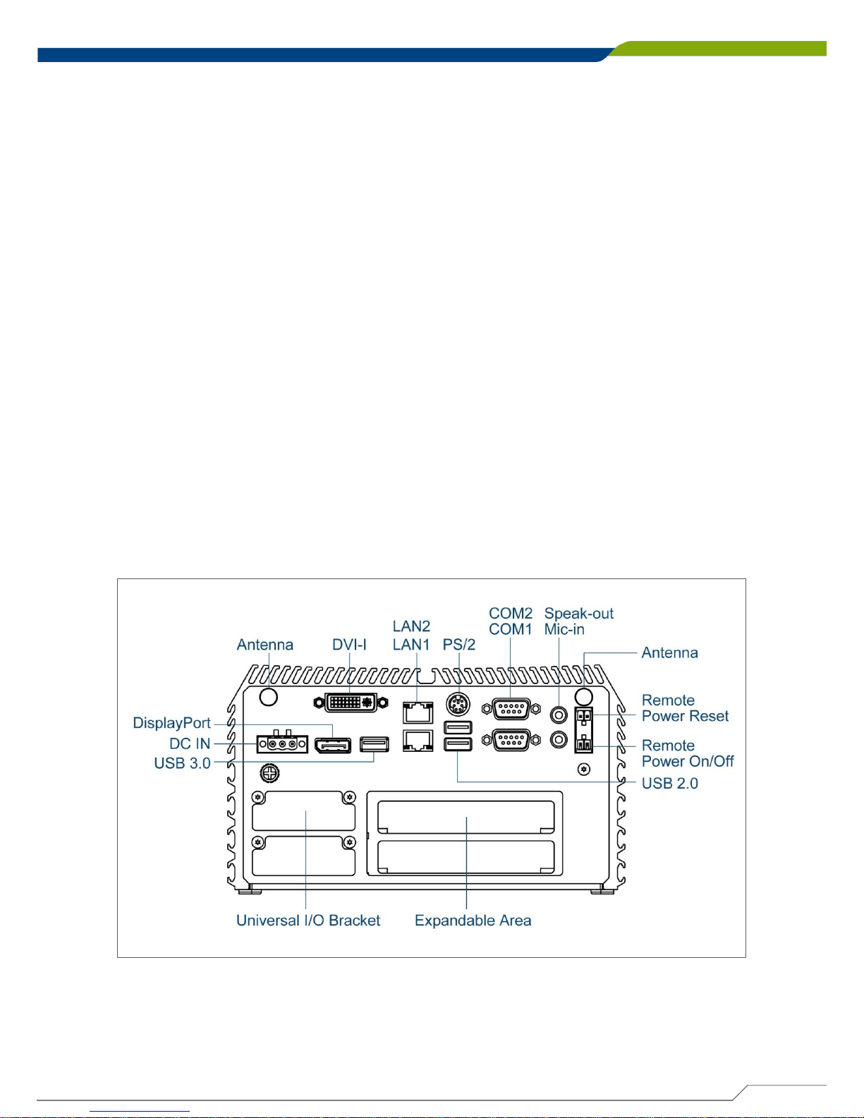
Rear Panel
DC IN
Used to plug a DC power input with terminal block
DVI-I port
Used to connect a DVI monitor or connect optional
split cable for dual display mode
PS/2 Port
Used to connect the PS/2 device
LAN port
Used to connect the system to a local area network
USB 3.0 port
Used to connect USB 3.0/2.0/1.1 device
USB 2.0 port
Used to connect USB 2.0/1.1 device
DisplayPort
Used to connect a DisplayPort monitor
Antenna hole
Used to connect an antenna for optional Mini-PCIe
WiFi module
COM port
COM 1 ~ COM 2 support RS232/422/485 serial device
Mic-in
Used to connect a microphone
Speaker-out
Used to connect a speaker
Remote Power on/off and Remote Power
Reset Terminal Block
Used to plug a remote power on/off and remote power
reset with terminal block
Universal I/O Bracket
Used to customized I/O output
Page 24
DE-1000
Power Efficient Fanless Computer
| User’s Manual
24
Chapter 1: Product Introductions
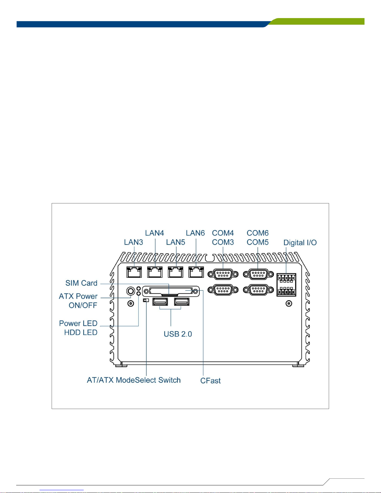
1.3.6 DE-1002(L/P)
Front Panel
ATX power on/off switch
Press to power-on or power-off the system
Power LED
Indicates the power status of the system
HDD LED
Indicates the status of the hard drive
USB 2.0 port
Used to connect USB 2.0/1.1 device
AT/ATX mode select switch
Used to select AT or ATX power mode
CFast and SIM card
Used to insert a CFast card and SIM card
COM port
COM 3 ~ COM6 support RS232/422/485 serial device
Digital I/O Terminal Block
The Digital I/O terminal block supports 4 digital input
and 4 digital output
Page 25
DE-1000
Power Efficient Fanless Computer
| User’s Manual
25
Chapter 1: Product Introductions
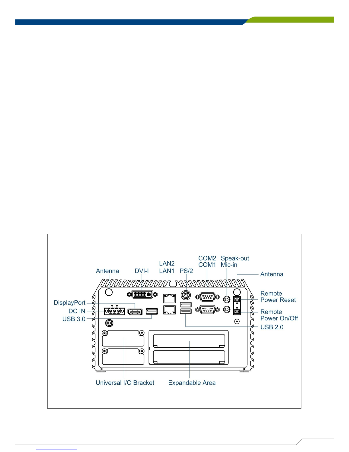
Rear Panel
DC IN
Used to plug a DC power input with terminal block
DVI-I port
Used to connect a DVI monitor or connect optional
split cable for dual display mode
PS/2 Port
Used to connect the PS/2 device
LAN port
Used to connect the system to a local area network
USB 3.0 port
Used to connect USB 3.0/2.0/1.1 device
USB 2.0 port
Used to connect USB 2.0/1.1 device
DisplayPort
Used to connect a DisplayPort monitor
Antenna hole
Used to connect an antenna for optional Mini-PCIe
WiFi module
COM port
COM 1 ~ COM 2 support RS232/422/485 serial device
Mic-in
Used to connect a microphone
Speaker-out
Used to connect a speaker
Remote Power on/off and Remote Power
Reset Terminal Block
Used to plug a remote power on/off and remote power
reset with terminal block
Universal I/O Bracket
Used to customized I/O output
Page 26
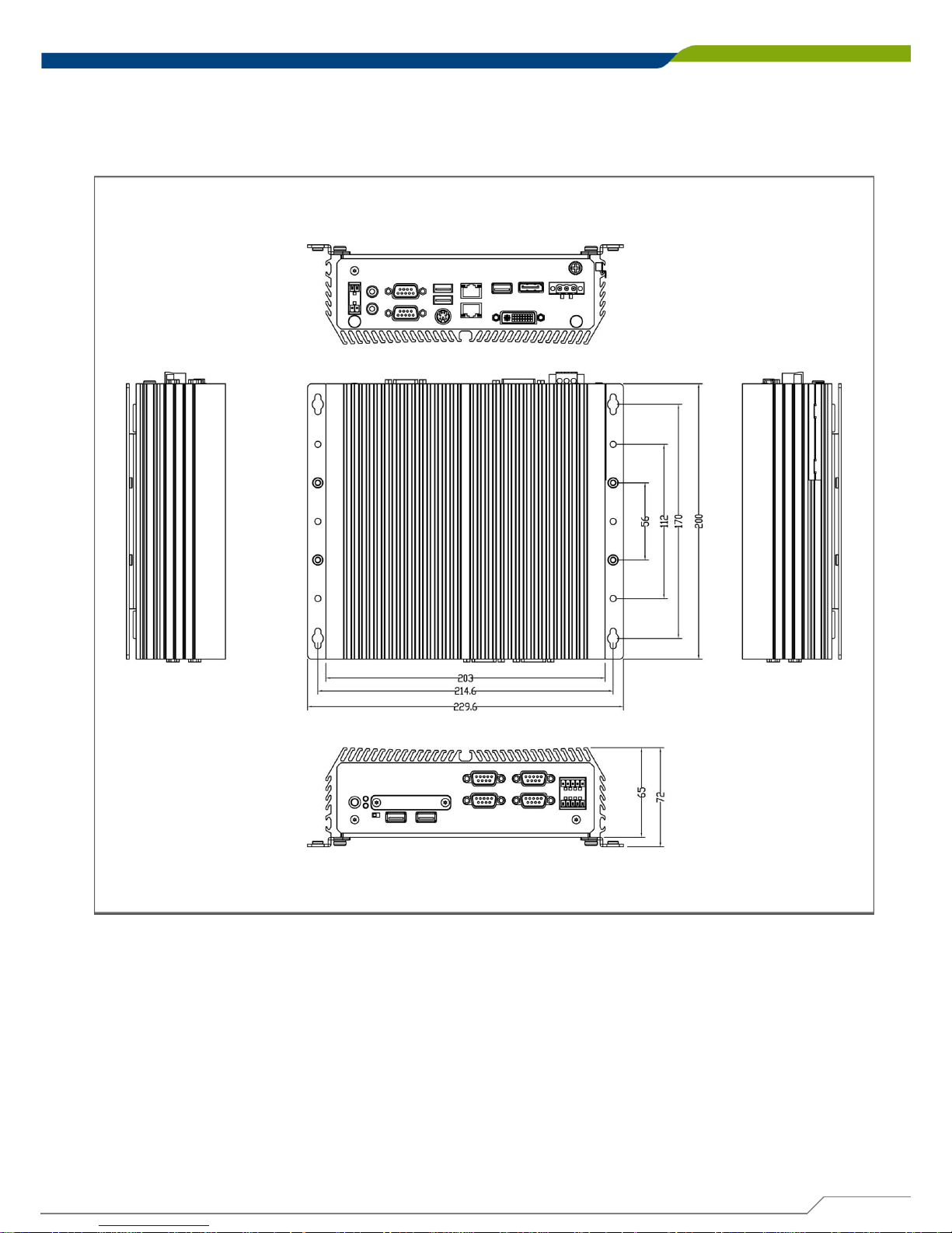
DE-1000
Power Efficient Fanless Computer
| User’s Manual
26
Chapter 1: Product Introductions
1.4 Mechanical Dimensions
1.4.1 DE-1000
Unit: mm
Page 27
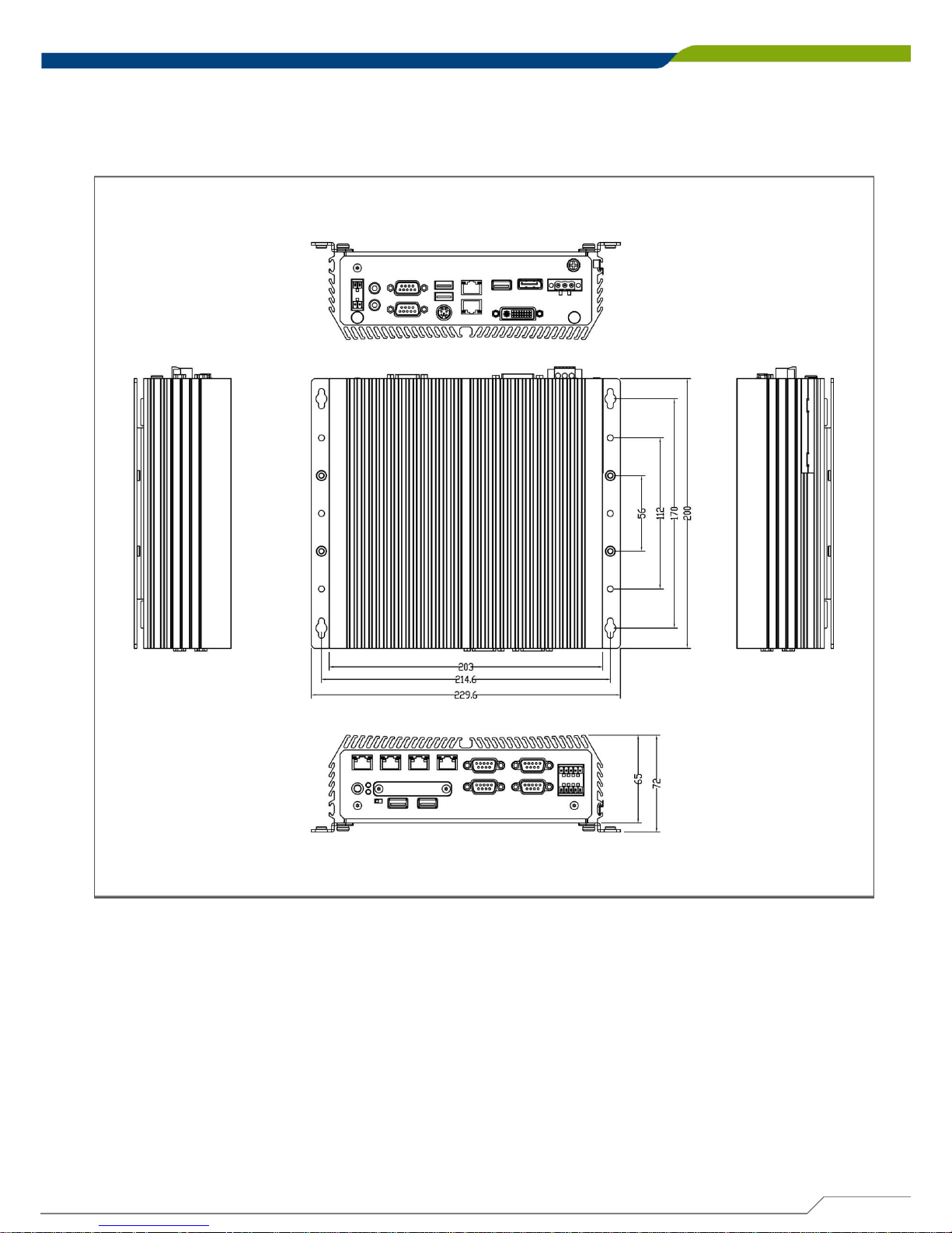
DE-1000
Power Efficient Fanless Computer
| User’s Manual
27
Chapter 1: Product Introductions
1.4.2 DE-1000(L/P)
Unit: mm
Page 28
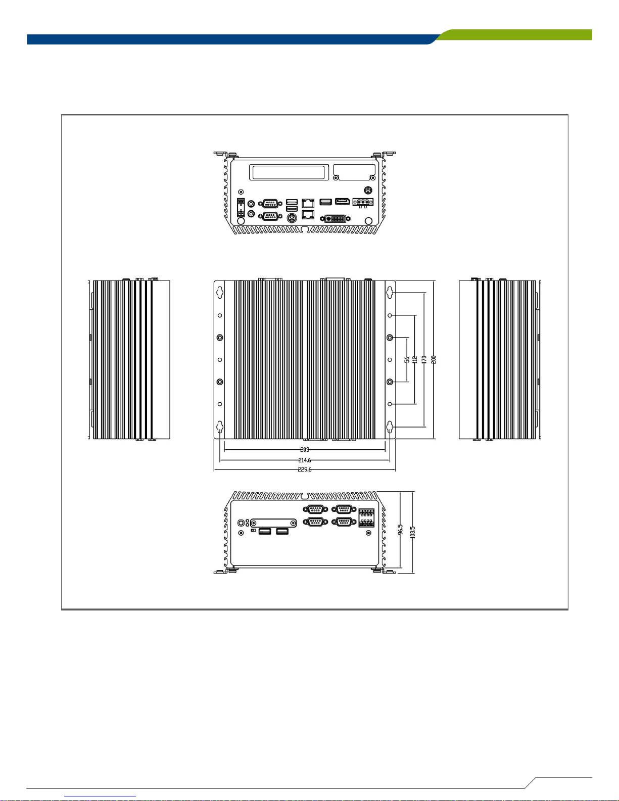
DE-1000
Power Efficient Fanless Computer
| User’s Manual
28
Chapter 1: Product Introductions
1.4.3 DE-1001
Unit: mm
Page 29
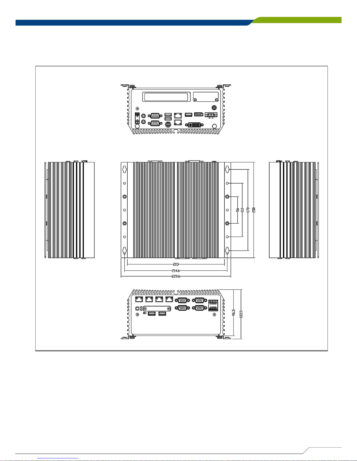
DE-1000
Power Efficient Fanless Computer
| User’s Manual
29
Chapter 1: Product Introductions
1.4.4 DE-1001(L/P)
Unit: mm
Page 30
DE-1000
Power Efficient Fanless Computer
| User’s Manual
30
Chapter 1: Product Introductions
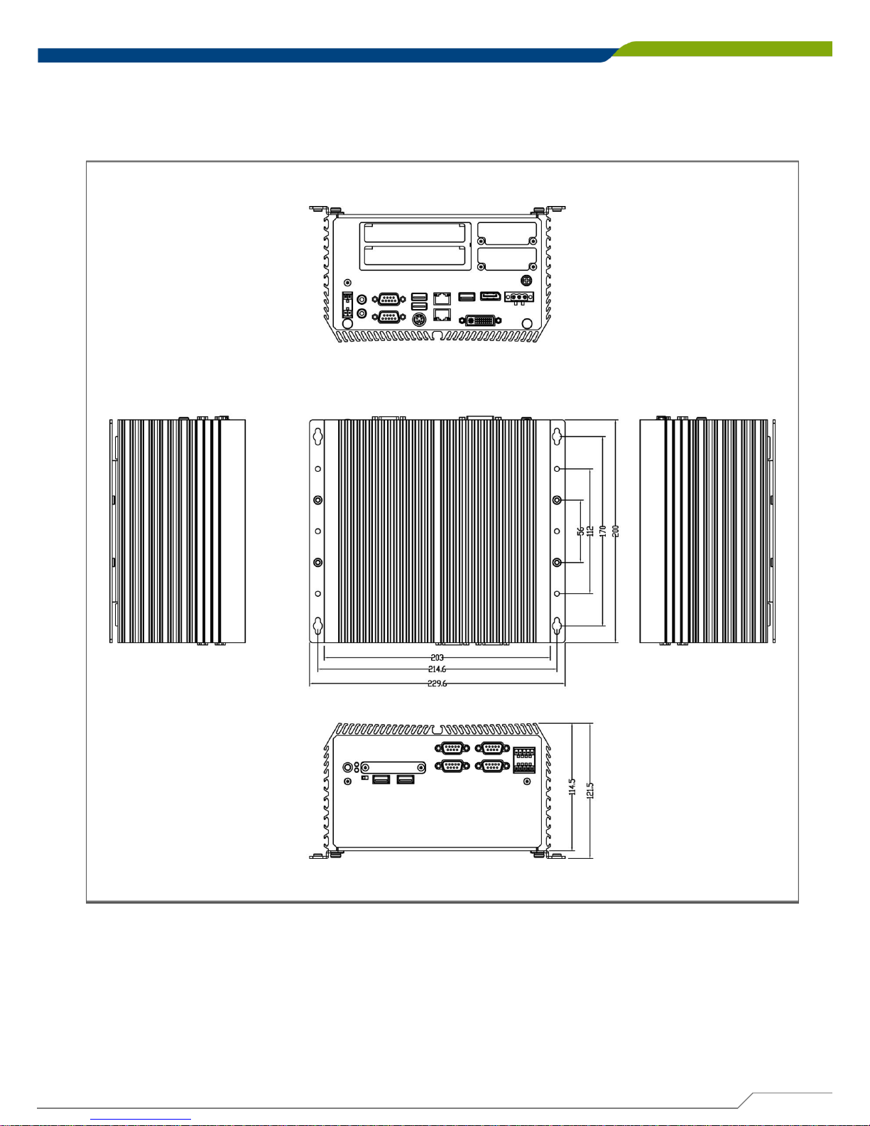
1.4.5 DE-1002
Unit: mm
Page 31
DE-1000
Power Efficient Fanless Computer
| User’s Manual
31
Chapter 1: Product Introductions
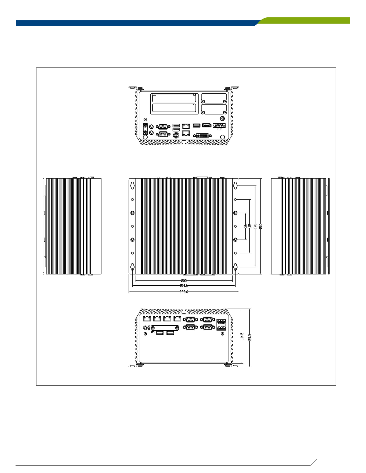
1.4.6 DE-1002(L/P)
Unit: mm
Page 32

Jumpers and Connectors
Chapter 2
Page 33
DE-1000
Power Efficient Fanless Computer
| User’s Manual
33
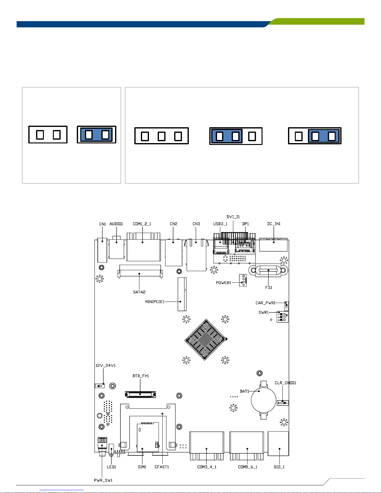
2.1 Jumpers Settings
When setting the jumpers, ensure that the jumper caps are placed on the correct pins. When
the jumper cap is placed on both pins, the jumper is short. If you remove the jumper cap, or
place the jumper cap on just one pin, the jumper is open. Refer to below for examples of the 2pin and 3-pin jumpers when they are short (on) and open (off).
Chapter 2: Jumpers and Connectors
1
2
Open
1 2
Short
Two-Pin Jumpers
1
2 3
Pins 1 and 2 are short
1
2
3
All pins are open
1
2 3
Pins 2 and 3 are short
Three-Pin Jumpers
2.2 Locations of the Jumpers and Connectors
2.2.1 Top View
Page 34
DE-1000
Power Efficient Fanless Computer
| User’s Manual
34
Chapter 2: Jumpers and Connectors
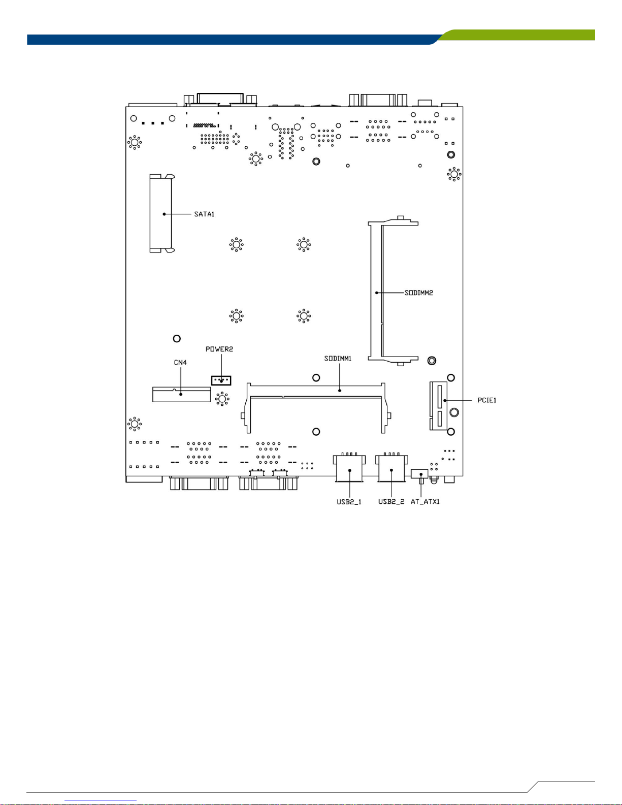
2.2.2 Bottom View
Page 35
DE-1000
Power Efficient Fanless Computer
| User’s Manual
35
Chapter 2: Jumpers and Connectors
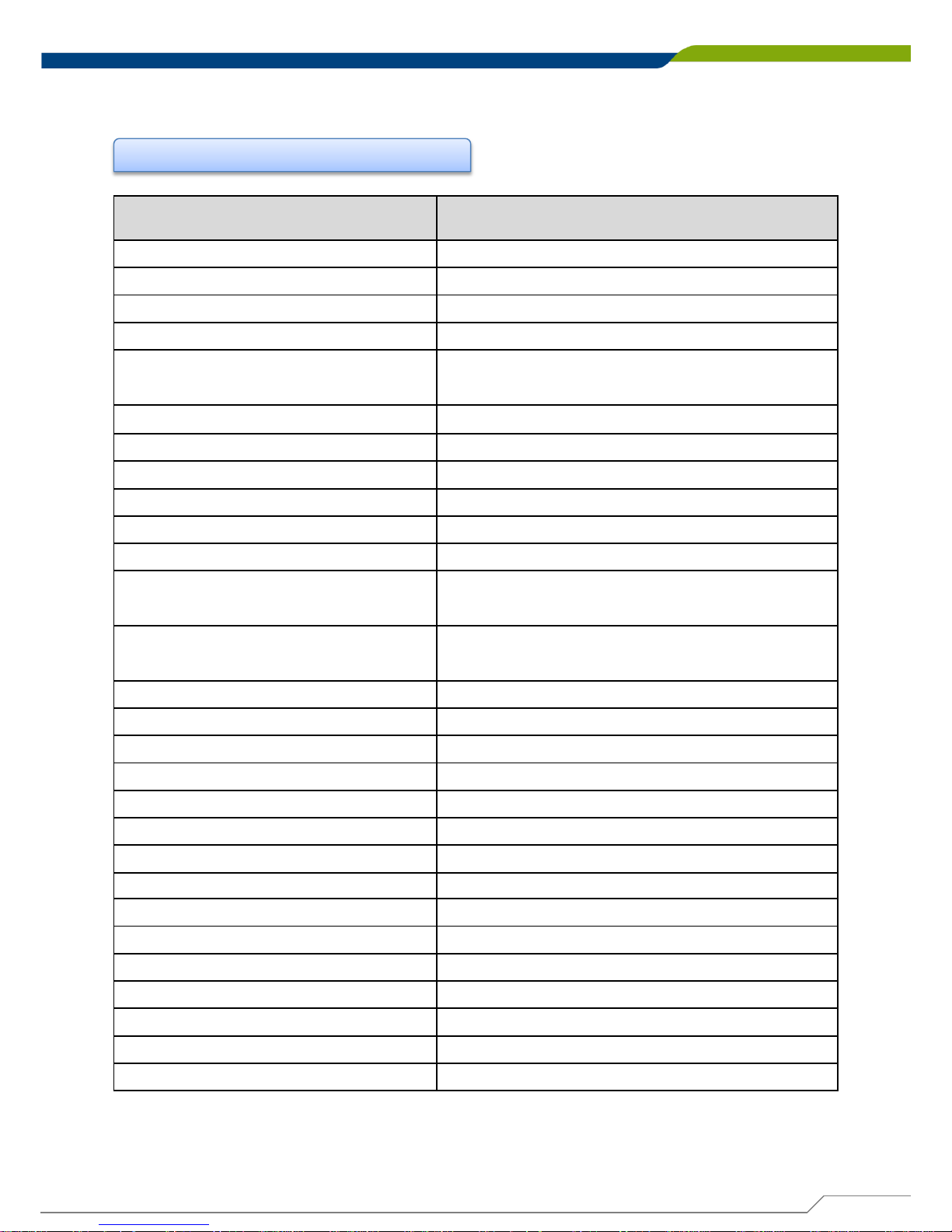
2.3 Connector / Jumper / Switch Definition
List of Connector / Jumper / Switch
Connector Location
Definition
12V_24V_1
12V / 24V Car Battery Switch
AT_ATX1
AT / ATX Power Mode Switch
AUDIO
1
Audio Jack
CAR_PWR
1
Car Power Enable / Disable Switch
CFAST
1
CFast
Connector
CLR_CMOS1
Clear BIOS Switch
CN1
Remote Power on / off Switch
CN2
PS/2 and USB2.0 Ports
CN3
LAN1
and LAN2 Ports
CN4
Mini PCI
-Express / mSATA Socket
COM1_2_1,
COM3_4_1, COM5_6_1
RS232 / RS422 / RS485 Connector
COM12_SEL1, COM34_SEL1,
COM56_SEL1
COM1 / COM2 / COM3 / COM4 / COM5 / COM6
with Power Select
DC_IN
1
3
-pin DC 9~48V
Power Input with Power Ignition
Connector
DIO1
4DI / 4DO Connector
DP1
DisplayPort
Connector
DVI_I
1
DVI
-I Connector
LED1
System LED Connector
MINIPCIE
1
Mini PCI
-Express Socket
PCIE
1
PCI
-Express X1 Socket
POWER
1
Power Connector
POWER2
Power Connector
PWR_SW
1
Power Switch
SATA
1, SATA2
SATA with Power Connector
SIM
1
SIM Card Socket
SW1 System Power off Timing Setting
SW2 MCU Programming Switch
USB2_1, USB2_2
USB 2.0
Ports
USB3_1
USB 3.0 Port
Page 36
DE-1000
Power Efficient Fanless Computer
| User’s Manual
Pin Definition
1-2
24V Car Battery Input
(Default)
2-3
12V Car Battery Input
36
Chapter 2: Jumpers and Connectors
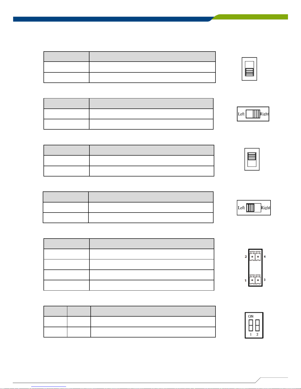
2.4 Switches Definition
12V_24V_1: 12V / 24V Car Battery Switch
AT_ATX1: AT / ATX Power Mode Switch
Pin Definition
1-2 (Left)
AT Power Mode
2-3 (Right)
ATX Power Mode (
Default)
CAR_PWR1: Car Power Enable / Disable Switch
Pin Definition
1-2
Car Power Disable (
Default)
2-3
Car Power Enable
CLR_CMOS1: Clear BIOS Switch
Pin Definition
1-2 (Left)
Normal Status (Default)
2-3 (Right)
Clear BIOS
CN1: Remote Power on / off Switch
Pin Definition
1 PWR_SW
2 RESET_SW
3 GND
4 GND
SW2: MCU Programming Switch
Pin 1 Pin 2 Definition
OFF OFF MCU Programming Off (Default)
ON ON MCU Programming On
Page 37
DE-1000
Power Efficient Fanless Computer
| User’s Manual
37 37
Chapter 2: Jumpers and Connectors
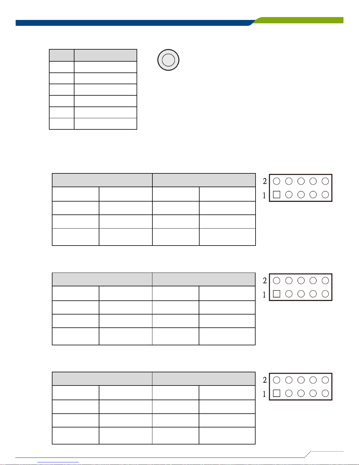
PWR_SW1: Power Switch
2.5 Jumpers Definition
COM12_SEL1: COM1 / COM2 with Power Select
Connector Type: 2X5 10-pin Header, 2.54mm pitch
COM1 COM2
Pin Definition Pin Definition
1-3 On +5V 2-4 On +5V
3-5 On +12V 4-6 On +12V
7-9 On
(Default)
RI1
8-10 On
(Default)
RI2
COM34_SEL1: COM3 / COM4 with Power Select
Connector Type: 2X5 10-pin Header, 2.54mm pitch
COM3 COM4
Pin Definition Pin Definition
1-3 On +5V 2-4 On +5V
3-5 On +12V 4-6 On +12V
7-9 On
(Default)
RI3
8-10 On
(Default)
RI4
Pin Definition
1 NC
2 Power Button
3 NC
4 GND
5 NC
6 GND
COM56_SEL1: COM5 / COM6 with Power Select
Connector Type: 2X5 10-pin Header, 2.54mm pitch
COM5 COM6
Pin Definition Pin Definition
1-3 On +5V 2-4 On +5V
3-5 On +12V 4-6 On +12V
7-9 On
(Default)
RI3
8-10 On
(Default)
RI4
Page 38
DE-1000
Power Efficient Fanless Computer
| User’s Manual
38
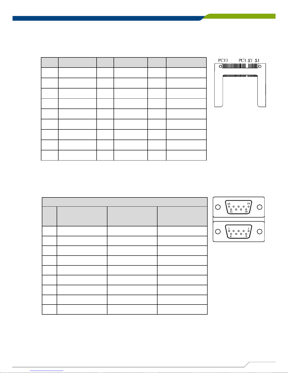
2.6 Connector Definition
CFAST1: CFast (Cerebrospinal Fluid Artifact Suppression Technique) Connector
Pin
Definition Pin Definition Pin Definition
S1 GND PC1
NC
PC10
NC
S2 TX+ PC2
GND
PC11
NC
S3 TX- PC3
NC
PC12
NC
S4 GND PC4
NC
PC13
+3.3V
S5 RX- PC5
NC
PC14
+3.3V
S6 RX+ PC6
NC
PC15
GND
S7 GND PC7
GND
PC16
GND
PC8
NC
PC17
NC
PC9
NC
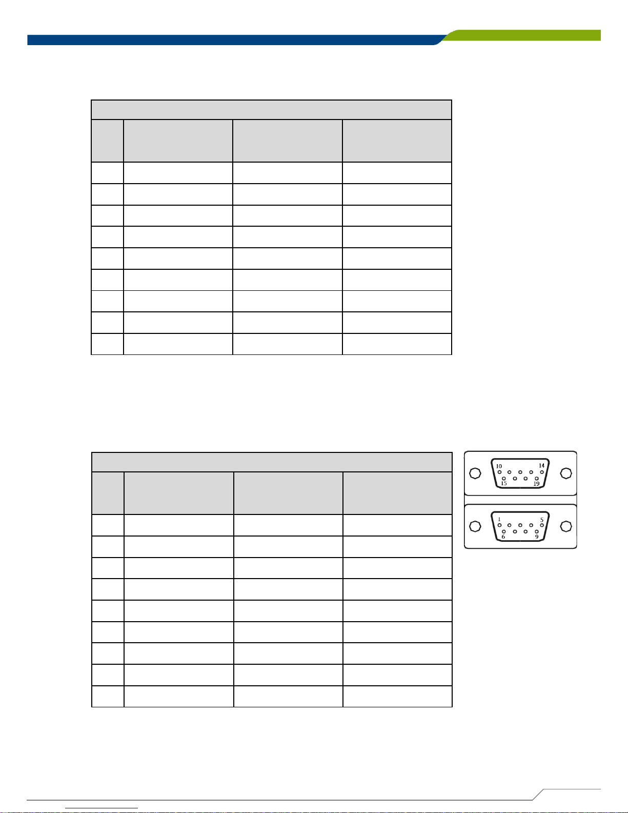
COM1_2_1: RS232 / RS422 / RS485 Connector
Connector Type: 9-pin D-Sub
COM1
Pin RS232 Definition
RS422 / 485 Full
Duplex Definition
RS485 Half
Duplex Definition
1 DCD1 TX1- DATA12 RxD1 TX1+ DATA1+
3 TxD1 RX1+
4 DTR1 RX1-
5 GND1
6 DSR1
7 RTS1
8 CTS1
9 RI1
Page 39
DE-1000
Power Efficient Fanless Computer
| User’s Manual
39
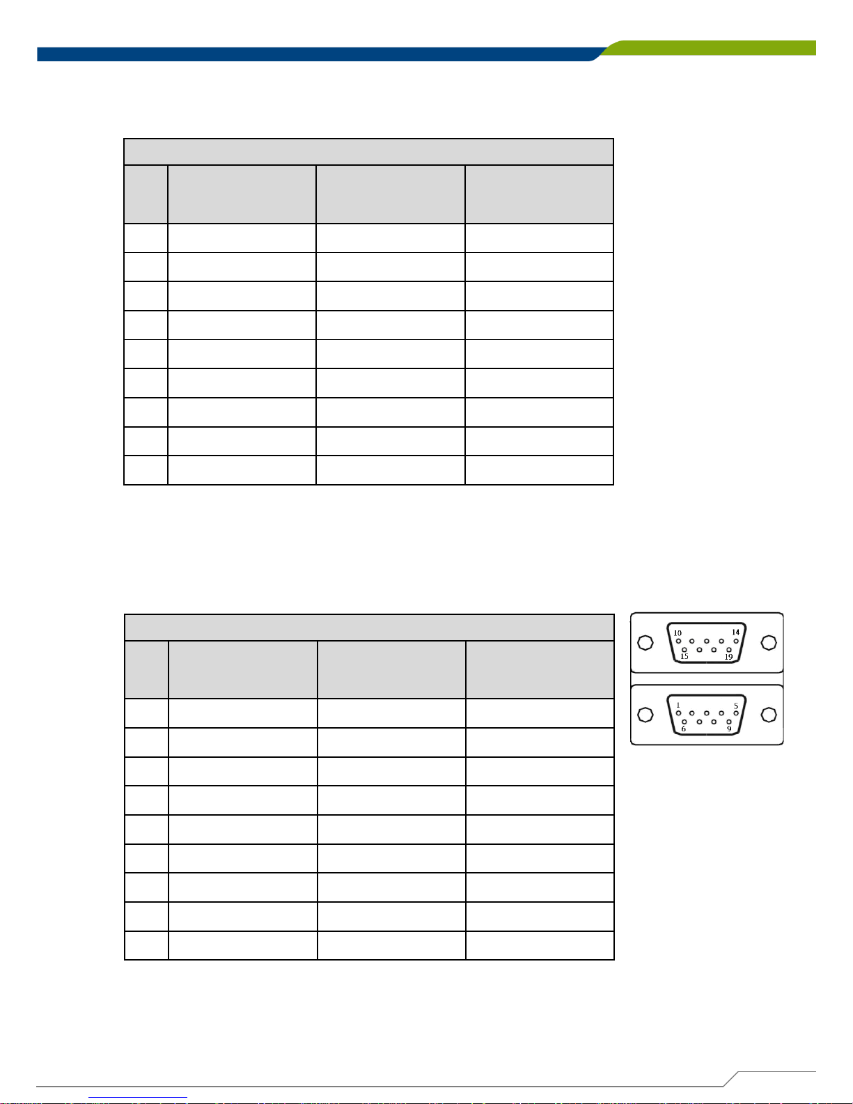
COM2
Pin RS232 Definition
RS422 / 485 Full
Duplex Definition
RS485 Half
Duplex Definition
1 DCD2 TX2- DATA22 RxD2 TX2+ DATA2+
3 TxD2 RX2+
4 DTR2 RX2-
5 GND2
6 DSR2
7 RTS2
8 CTS2
9 RI2
COM3_4_1: RS232 / RS422 / RS485 Connector
Connector Type: 9-pin D-Sub
COM3
Pin RS232 Definition
RS422 / 485 Full
Duplex Definition
RS485 Half
Duplex Definition
1 DCD3 TX3- DATA32 RxD3 TX3+ DATA3+
3 TxD3 RX3+
4 DTR3 RX3-
5 GND3
6 DSR3
7 RTS3
8 CTS3
9 RI3
Page 40
DE-1000
Power Efficient Fanless Computer
| User’s Manual
40
COM4
Pin RS232 Definition
RS422 / 485 Full
Duplex Definition
RS485 Half
Duplex Definition
1 DCD4 TX4- DATA4-
2 RxD4 TX4+ DATA4+
3 TxD4 RX4+
4 DTR4 RX4-
5 GND4
6 DSR4
7 RTS4
8 CTS4
9 RI4
COM5_6_1: RS232 / RS422 / RS485 Connector
Connector Type: 9-pin D-Sub
COM5
Pin RS232 Definition
RS422 / 485 Full
Duplex Definition
RS485 Half
Duplex Definition
1 DCD5 TX5- DATA52 RxD5 TX5+ DATA5+
3 TxD5 RX5+
4 DTR5 RX5-
5 GND5
6 DSR5
7 RTS5
8 CTS5
9 RI5
Page 41
DE-1000
Power Efficient Fanless Computer
| User’s Manual
41
COM6
Pin RS232 Definition
RS422 / 485 Full
Duplex Definition
RS485 Half
Duplex Definition
1 DCD6 TX6- DATA62 RxD6 TX6+ DATA6+
3 TxD6 RX6+
4 DTR6 RX6-
5 GND6
6 DSR6
7 RTS6
8 CTS6
9 RI6
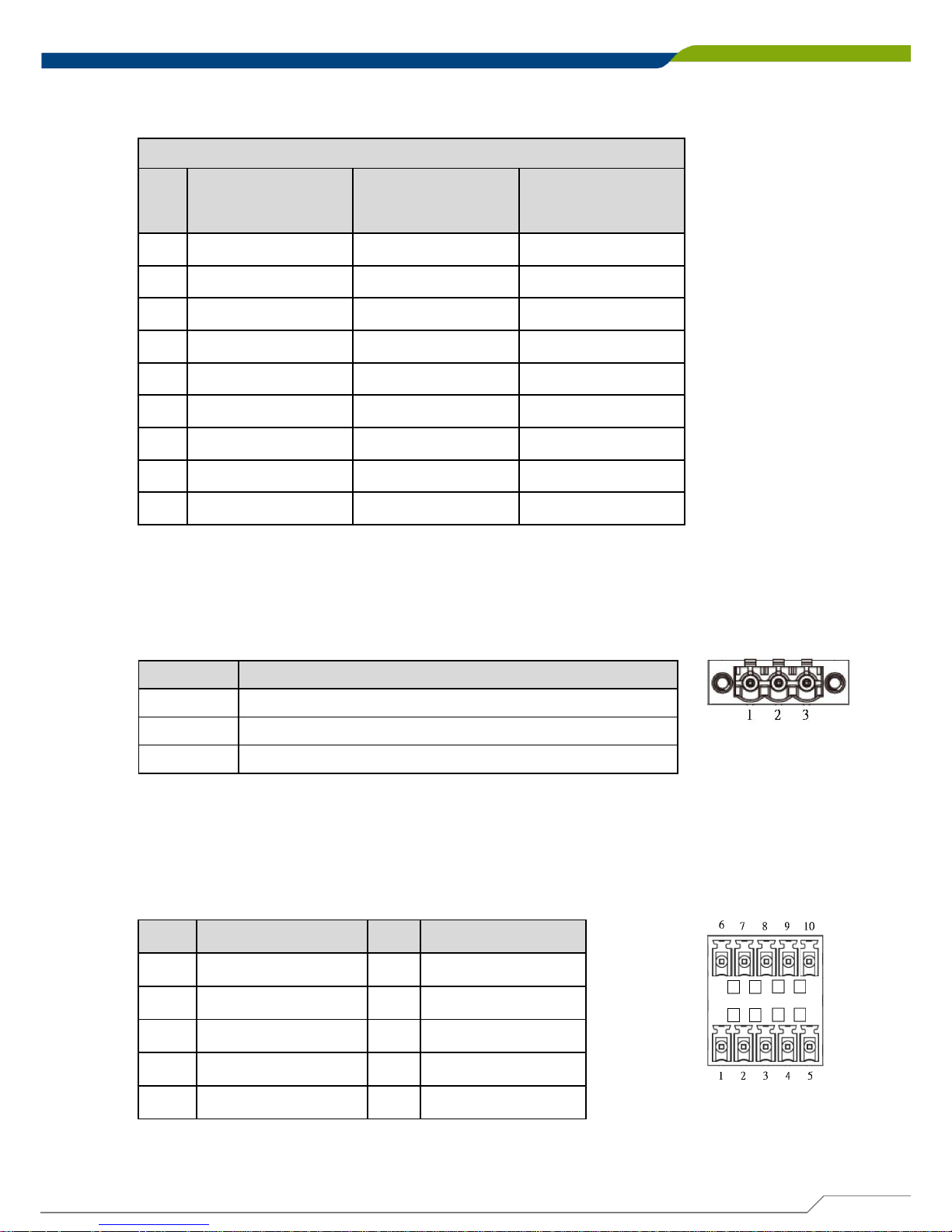
DC_IN1: DC Power Input Connector (+9~48V)
Connector Type: Terminal Block 1X3 3-pin, 5.0mm pitch
Pin Definition
1
+
9~48VIN
2
Chassis GND
3
GND
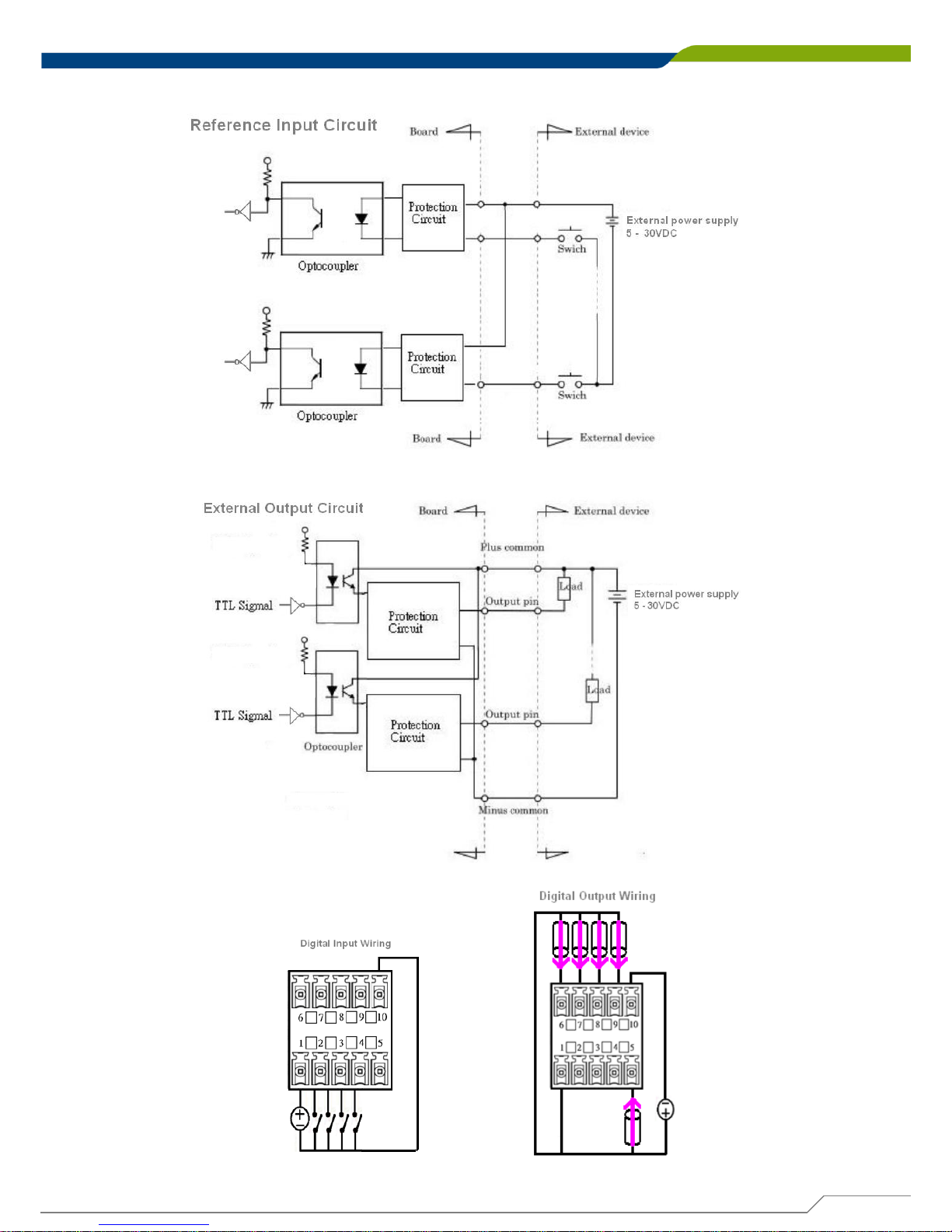
DIO1: Digital Input / Output Connector
Connector Type: Terminal Block 2X5 10-pin, 3.5mm pitch
Pin
Definition Pin
Definition
1 DC INPUT 6 DO1
2 DI1 7 DO2
3 DI2 8 DO3
4 DI3 9 DO4
5 DI4 10 GND
Page 42
DE-1000
Power Efficient Fanless Computer
| User’s Manual
42
Page 43
DE-1000
Power Efficient Fanless Computer
| User’s Manual
43
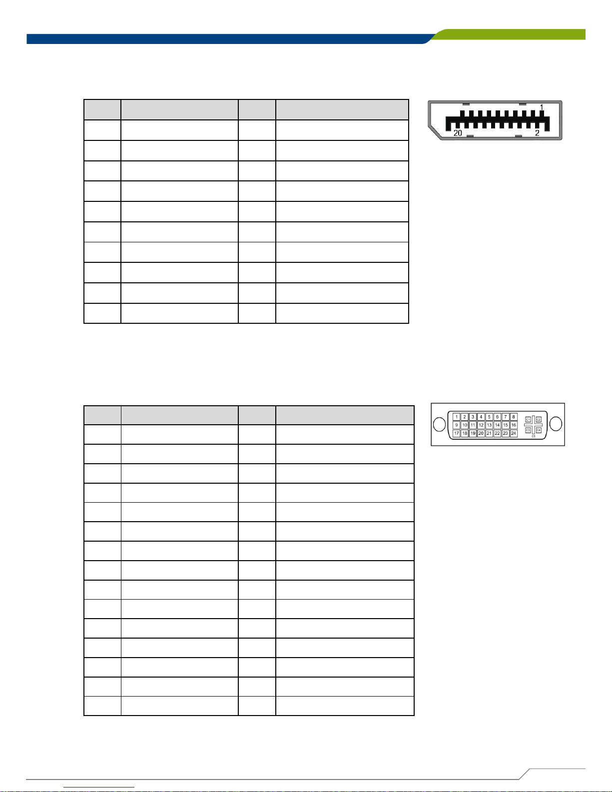
DP1: DisplayPort Connector
Pin
Definition Pin
Definition
1 DPC_LANE0_P 11 GND
2 GND 12 DPC_LANE3_N
3 DPC_LANE0_N 13 GND
4 DPC_LANE1_P 14 GND
5 GND 15 DPC_AUX_P
6 DPC_LANE1_N 16 GND
7 DPC_LANE2_P 17 DPC_AUX_N
8 GND 18 DPC_HPD
9 DPC_LANE2_N 19 GND
10 DPC_LANE3_P 20 DPC_PWR
DVI_I1: DVI-I Connector
Pin
Definition Pin
Definition
1 DVI_TX2- 16 DVI Hot Plug Detect
2 DVI_TX2+ 17 DVI_TX03 GND 18 DVI_TX0+
4 NC 19 GND
5 NC 20 NC
6 DDC_CLOCK 21 NC
7 DDC_DATA 22 GND
8 VGA VSYNC 23 DVI_TXCLK+
9 DVI_TX1- 24 DVI_TXCLK-
10 DVI_TX1+ C1 VGA_RED
11 GND C2 VGA_GREEN
12 NC C3 VGA_BLUE
13 NC C4 VGA_HSYNC
14 +5V C5 GND
15 GND
Page 44
DE-1000
Power Efficient Fanless Computer
| User’s Manual
44
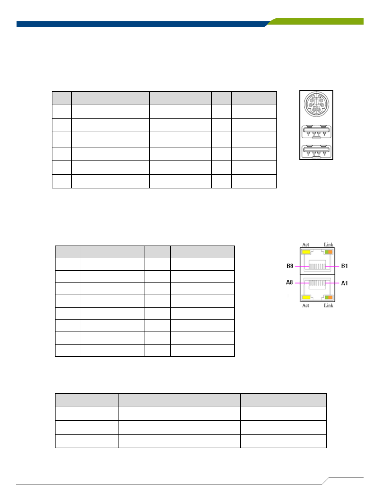
CN2: PS/2 and USB2.0 Ports
Connector Type: 6-pin Mini-DIN and dual USB 2.0 ports
Pin
Definition Pin
Definition Pin Definition
1 +5V 5 +5V 9 +5V
2 USB_HUB_D1-
6 USB_HUB_D2- 10 MS_DATA
3
USB_HUB_D1+
7
USB2_HUB_D2+
11
KB_DATA
4 GND 8 GND 12
GND
13
MS_CLK
14
KB_CLK
Pin Definition Pin Definition
A1 LAN1_MDI0P A5 LAN1_MDI2N
A2 LAN1_MDI0N A6 LAN1_MDI1N
A3 LAN1_MDI1P A7 LAN1_MDI3P
A4 LAN1_MDI2P A8 LAN1_MDI3N
B1 LAN2_MDI0P B5 LAN2_MDI2N
B2 LAN2_MDI0N B6 LAN2_MDI1N
B3 LAN2_MDI1P B7 LAN2_MDI3P
B4 LAN2_MDI2P B8 LAN2_MDI3N
CN3: LAN1 and LAN2 Ports
Connector Type: RJ45 with LEDs Port
Act LED Status
Definition Link LED Status Definition
Blinking Yellow Data Activity Steady Green 1Gbps Network Link
Off No Activity Steady Orange 100Mbps Network Link
Off 10Mbps Network Link
Page 45
DE-1000
Power Efficient Fanless Computer
| User’s Manual
45
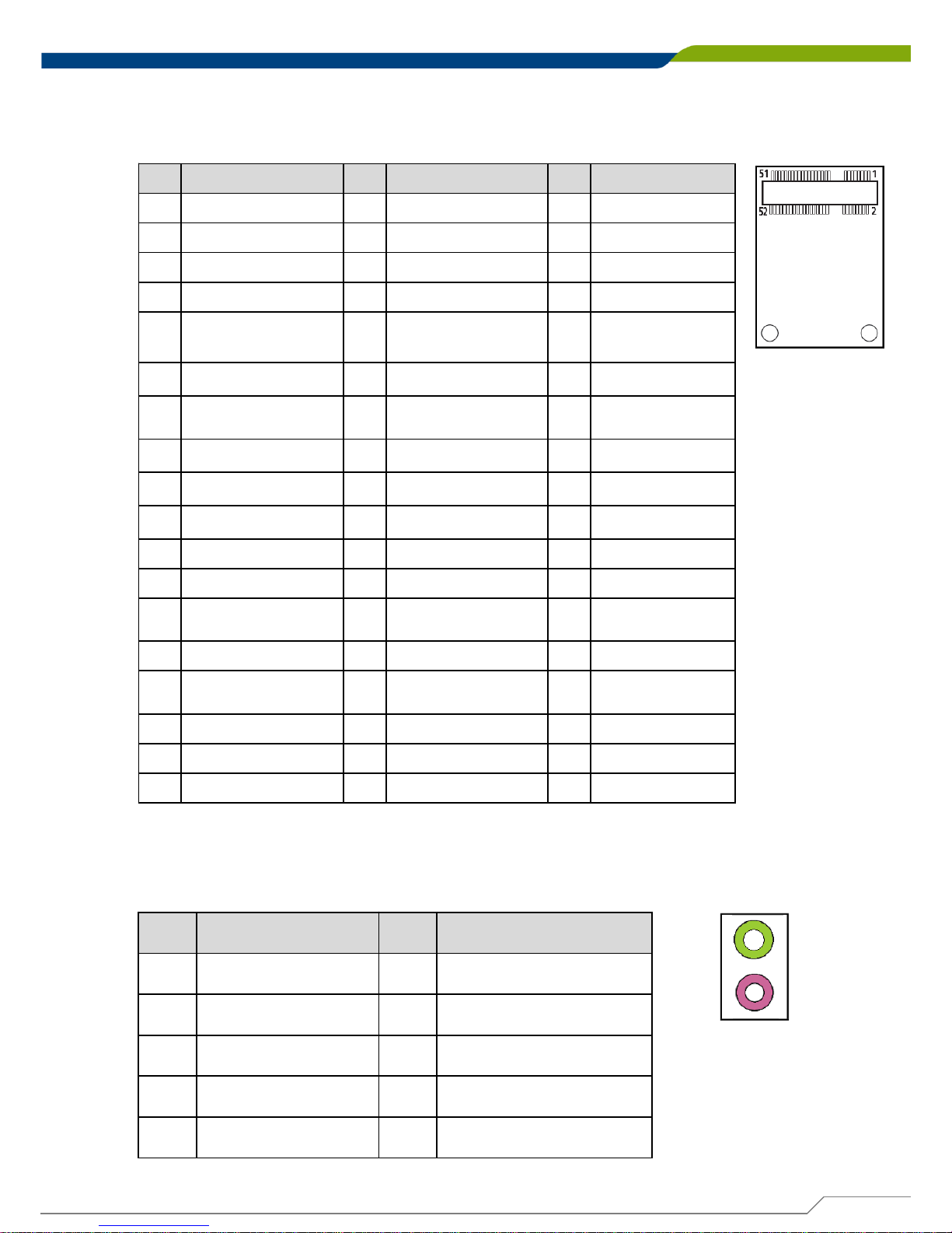
CN4: Mini PCI-Express / mSATA Socket
Pin
Definition
Pin
Definition
Pin
Definition
1 WAKE# 19
NC 37
GND
2 +3.3V 20
+3.3V 38
USB2_D+
3 NC 21
GND 39
+3.3V
4 GND 22 MINIPCIE RST# 40
GND
5 NC 23
MINIPCIE_RXN /
SATA_RXP
41
+3.3V
6 +1.5V 24
+3.3V 42
NC
7 CLKREQ# 25
MINIPCIE_RXP /
SATA_RXN
43
GND
8 NC 26
GND 44
NC
9 GND 27
GND 45
NC
10
NC 28
+1.5V 46
NC
11 MINIPCIE_CLKN 29
GND 47
NC
12
NC 30
SMB_CLK 48
+1.5V
13 MINIPCIE_CLKP 31
MINIPCIE_TXN /
SATA_TXN
49
NC
14
NC 32
SMB_DATA 50
GND
15
GND 33
MINIPCIE_TXP /
SATA_TXP
51
NC
16
NC 34
GND 52
+3.3V
17
NC 35
GND
18
GND 36
USB2_D-
AUDIO1: Speaker-out Jack (Green) and Microphone Jack (Pink)
Connector Type: 5-pin Phone Jack
Pin
Definition Pin
Definition
1 GND 22 OUT_L
2 MIC_L 23 GND
3 GND 24 OUT_JD
4 MIC_JD 25 OUT_R
5 MIC_R
Page 46
DE-1000
Power Efficient Fanless Computer
| User’s Manual
46
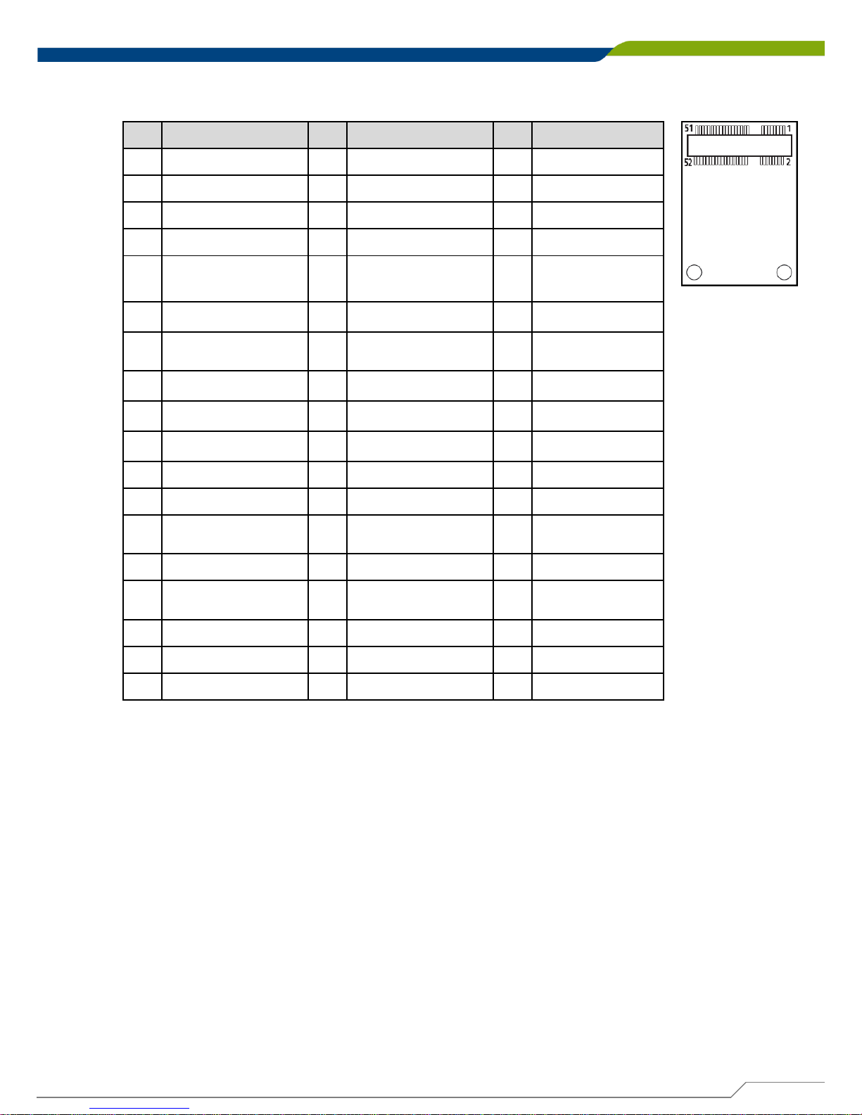
MINIPCIE1: Mini PCI-Express Socket
Pin
Definition
Pin
Definition
Pin
Definition
1 WAKE# 19
NC 37
GND
2 +3.3V 20
+3.3V 38
USB2_D+
3 NC 21
GND 39
+3.3V
4 GND 22 MINIPCIE RST# 40
GND
5 NC 23 MINIPCIE_RXN7 41
+3.3V
6 +1.5V 24
+3.3V 42
NC
7 CLKREQ# 25 MINIPCIE_RXP7 43
GND
8 UIM_PWR 26
GND 44
NC
9 GND 27
GND 45
NC
10
UIM_DATA 28
+1.5V 46
NC
11 MINIPCIE_CLKN 29
GND 47
NC
12
UIM_CLK 30
SMB_CLK 48
+1.5V
13 MINIPCIE_CLKP 31
MINIPCIE_TXN 49
NC
14
UIM_RESET 32
SMB_DATA 50
GND
15
GND 33
MINIPCIE_TXP 51
NC
16
UIM_VPP 34
GND 52
+3.3V
17
NC 35
GND
18
GND 36
USB2_D-
Page 47
DE-1000
Power Efficient Fanless Computer
| User’s Manual
47
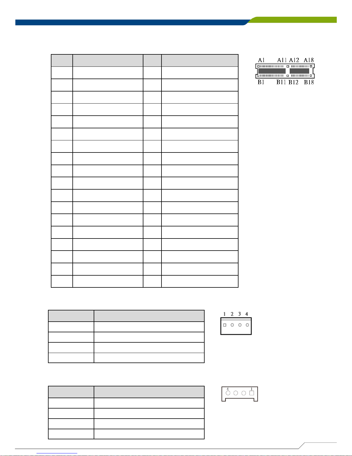
PCIE2: PCI-Express X1 Socket
Connector Type: PCI-Express X1 Slot
Pin
Definition Pin
Definition
A1
CPUFAN_ CONTROL
B1
+12V
A2 +12V B2
+12V
A3 +12V B3
+12V
A4 GND B4
GND
A5 NC B5
SMB_CLK
A6 NC B6
SMB_DATA
A7 NC B7
GND
A8 NC B8
+3.3V
A9 +3.3V B9
NC
A10
+3.3V
B10
+3.3VSB
A11
PCIE_RESET#
B11
PCIE_WAKE#
A12
GND
B12
+12V
A13
PCIE_CLKP
B13
GND
A14
PCIE_CLKN
B14
PCIE_TXP
A15
GND
B15
PCIE_TXN
A16
PCIE_RXP
B16
GND
A17
PCIE_RXN
B17
CPUFAN_SENSE
A18
GND
B18
GND
POWER1: Power Connector
Connector Type: 1X4-pin Wafer, 2.54mm pitch
Pin Definition
1 +5V
2 GND
3 GND
4 +12V
POWER2: Power Connector
Connector Type: 1X4-pin Wafer, 2.0mm pitch
Pin Definition
1 +5V
2 GND
3 GND
4 +12V
Page 48
DE-1000
Power Efficient Fanless Computer
| User’s Manual
48 48
Chapter 2: Jumpers and Connectors
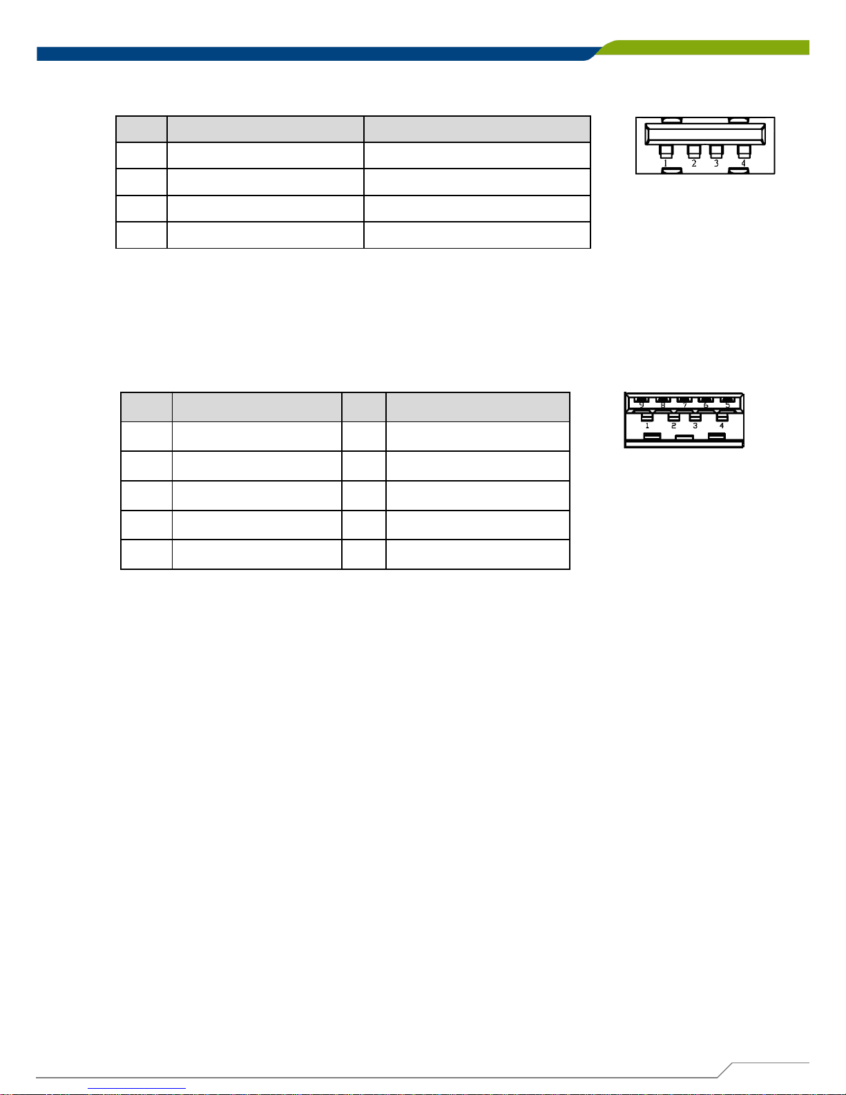
USB2_1, USB2_2: USB2.0 Connector, Type A
USB3_1: USB 3.0 Port , Type A
Pin
Definition Pin
Definition
1 +5V 6 USB3_RX+
2 USB_HUB_D5- 7 GND
3 USB_HUB_D5+ 8 USB3_TX4 GND 9 USB3_TX+
5 USB3_RX-
Pin
USB2_1 Definition USB2_2 Definition
1 +5V +5V
2 USB_HUB_D3- USB_HUB_D43 USB_HUB_D3+ USB_HUB_D4+
4 GND GND
Page 49

System Setup
Chapter 3
Page 50
DE-1000
Power Efficient Fanless Computer
| User’s Manual
50
Chapter 3: System Setup
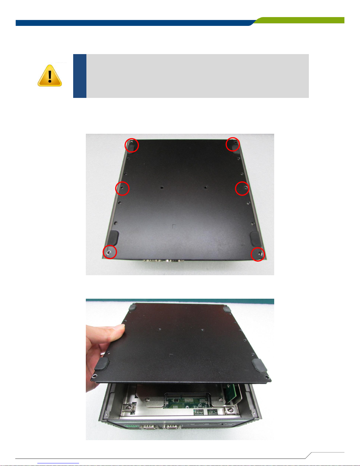
1. Flip over the unit to have the bottom side up. Loosen the 6 screws from bottom cover and
place them aside for later use.
3.1 Removing the Chassis Bottom Cover
In order to prevent electric shock or system damage, before removing
the chassis cover, must turn off power and disconnect the unit from
power source.
WARNING
2. Remove the cover from the chassis.
Page 51
DE-1000
Power Efficient Fanless Computer
| User’s Manual
51
Chapter 3: System Setup
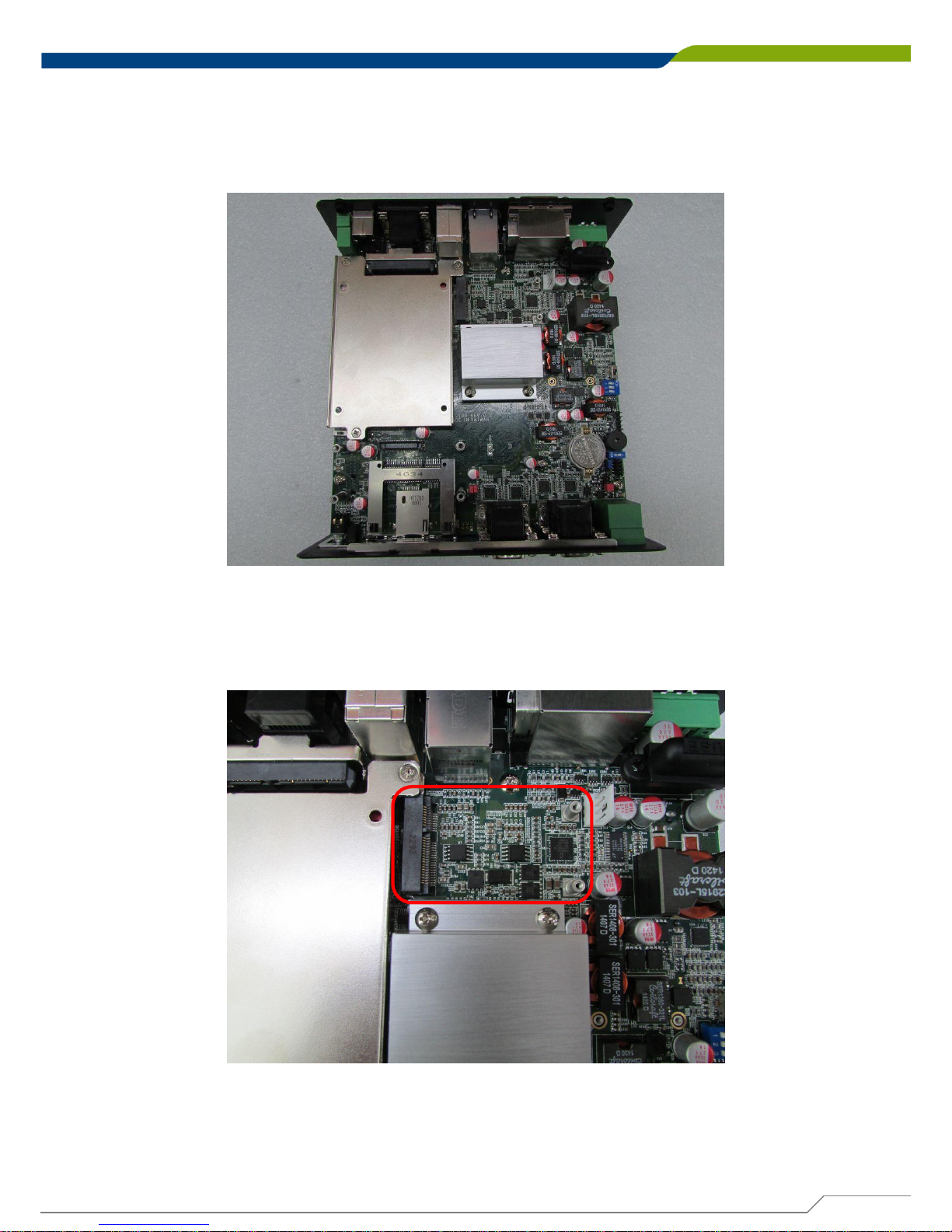
3.2 Removing the Chassis
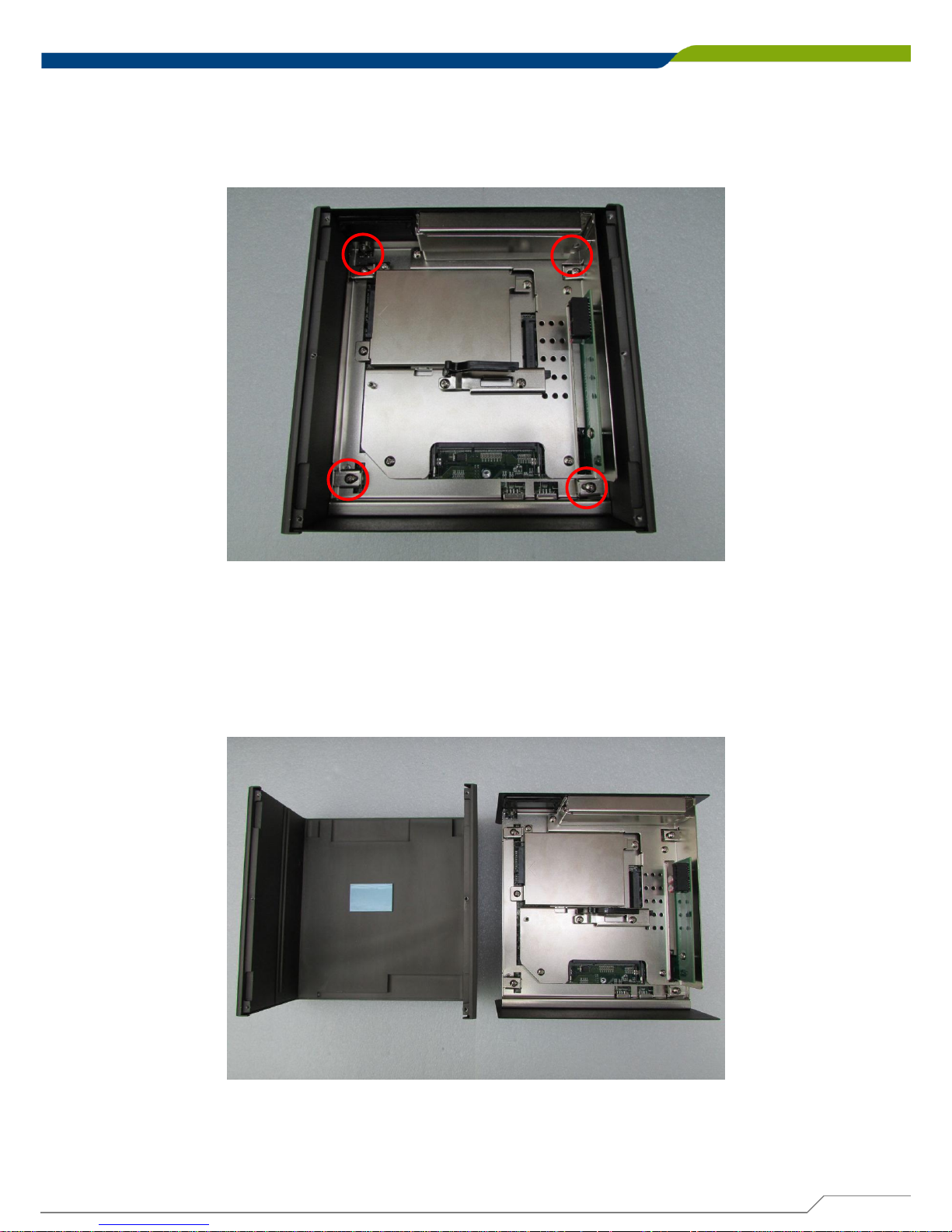
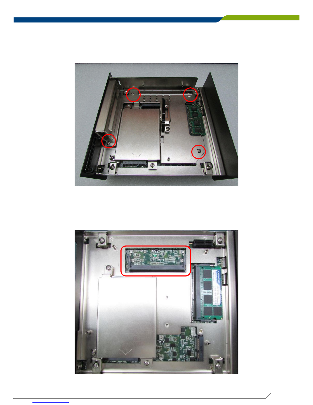
1. Loosen 4 screws as they are marked on photo, remove the base holders, and place them
aside for later use.
2. Lift up the body unit vertically by holding the front and rear panel.
Page 52
DE-1000
Power Efficient Fanless Computer
| User’s Manual
52
Chapter 3: System Setup
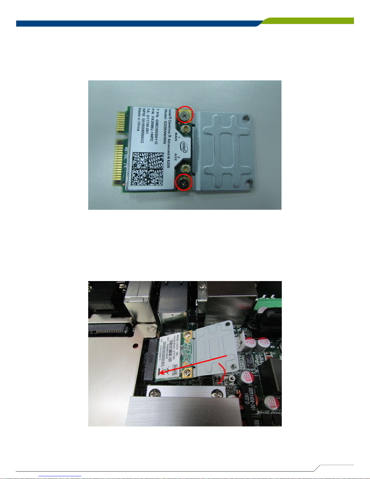
3.3 Installing a Half Size Mini PCIe Card on Upper Side
2. Locate the Mini PCIe slot.
1. Flip over the body unit and place it on the table gently.
Page 53
DE-1000
Power Efficient Fanless Computer
| User’s Manual
53
Chapter 3: System Setup
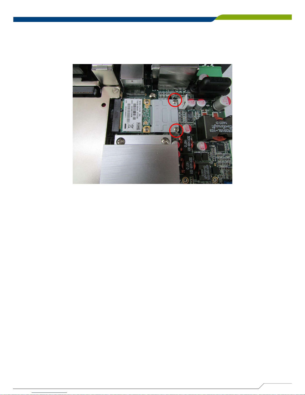
4. Tilt the Mini PCIe module at 45 degree angle and insert it to the Mini PCIe slot. Be sure the
gold-plated connects to the Mini PCIe slot firmly.
45°
3. Fasten the module and bracket together with 2 screws.
Page 54
DE-1000
Power Efficient Fanless Computer
| User’s Manual
54
Chapter 3: System Setup
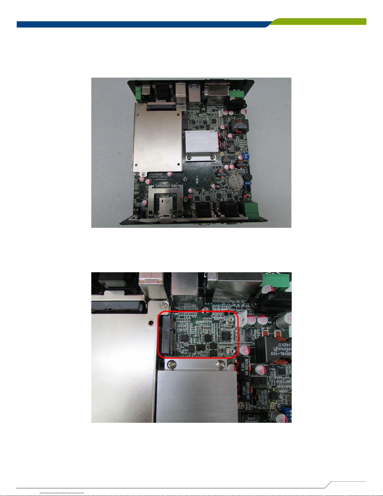
5. Press down the module and fasten the module with 2 screws.
Page 55
DE-1000
Power Efficient Fanless Computer
| User’s Manual
55
Chapter 3: System Setup
3.4 Installing a Full Size Mini PCIe Card on Upper Side
2. Locate the Mini PCIe slot.
1. Flip over the body unit and place it on the table gently.
Page 56
DE-1000
Power Efficient Fanless Computer
| User’s Manual
56
Chapter 3: System Setup
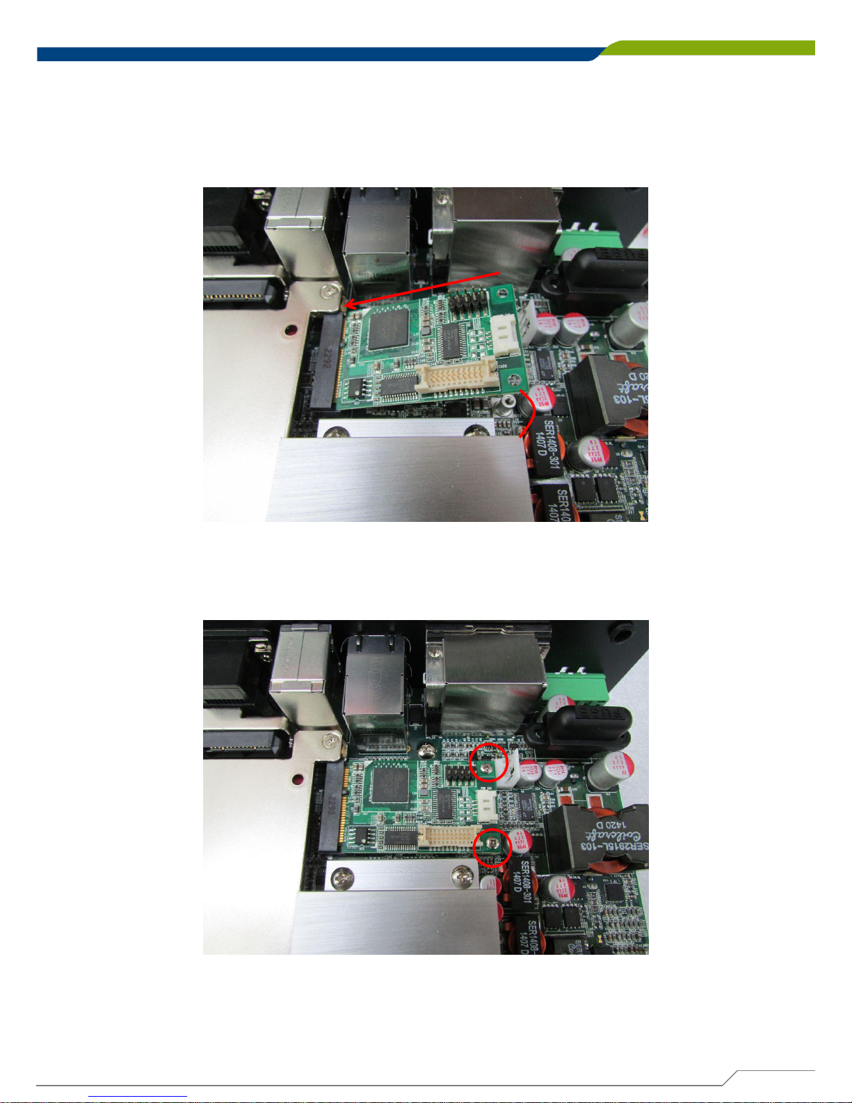
4. Press down the module and fasten the module with 2 screws.
3. Tilt the Mini PCIe module at 45 degree angle and insert it to the Mini PCIe slot. Be sure the
gold-plated connects to the Mini PCIe slot firmly.
45°
Page 57
DE-1000
Power Efficient Fanless Computer
| User’s Manual
57
Chapter 3: System Setup
3.5 Installing Antenna
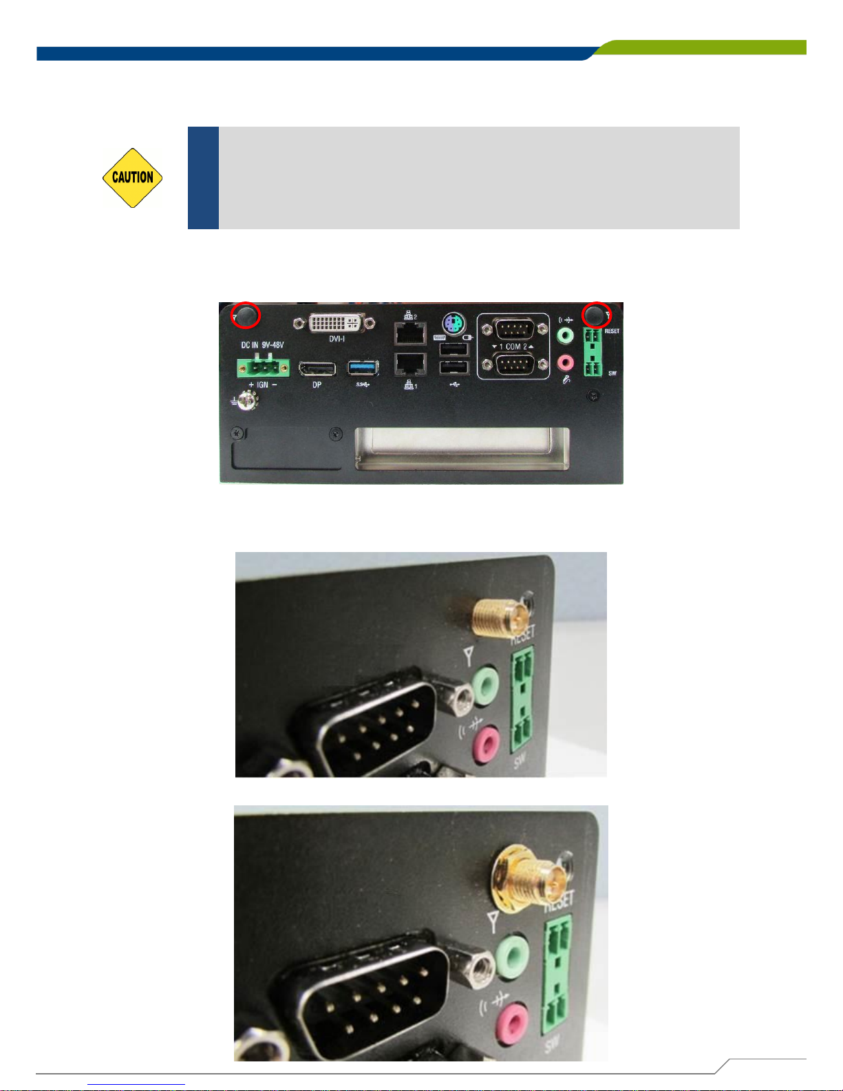
1. Remove the antenna covers on rear panel.
2. Have antenna jack penetrate through the hole.
3. Place on washer and fasten the nut with antenna jack.
Please installing a Mini PCIe Wireless LAN Card on top side before you
put on washer and fasten the nut with antenna jack.
CAUTION
Page 58
DE-1000
Power Efficient Fanless Computer
| User’s Manual
58
Chapter 3: System Setup
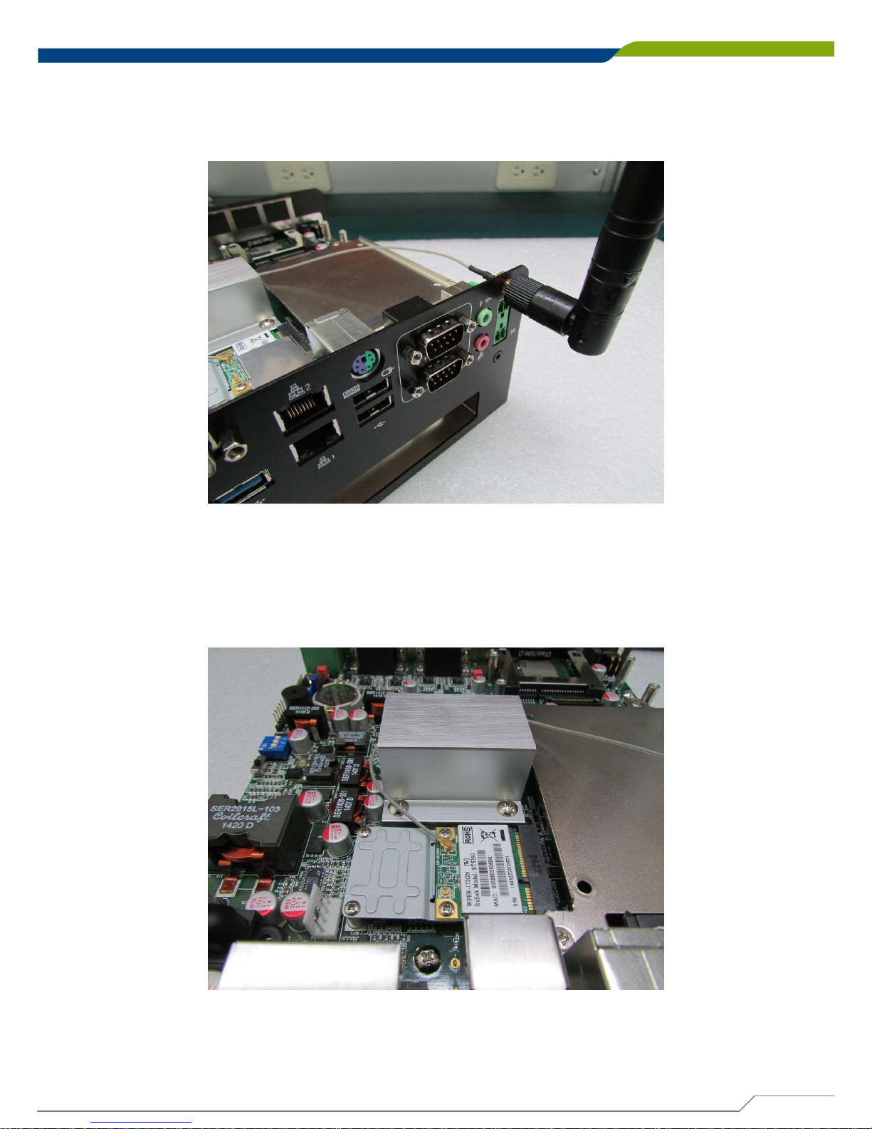
4. Assemble the antenna and antenna jack together.
5. Attach the RF connector at the other end of cable onto the module.
Page 59
DE-1000
Power Efficient Fanless Computer
| User’s Manual
59
Chapter 3: System Setup
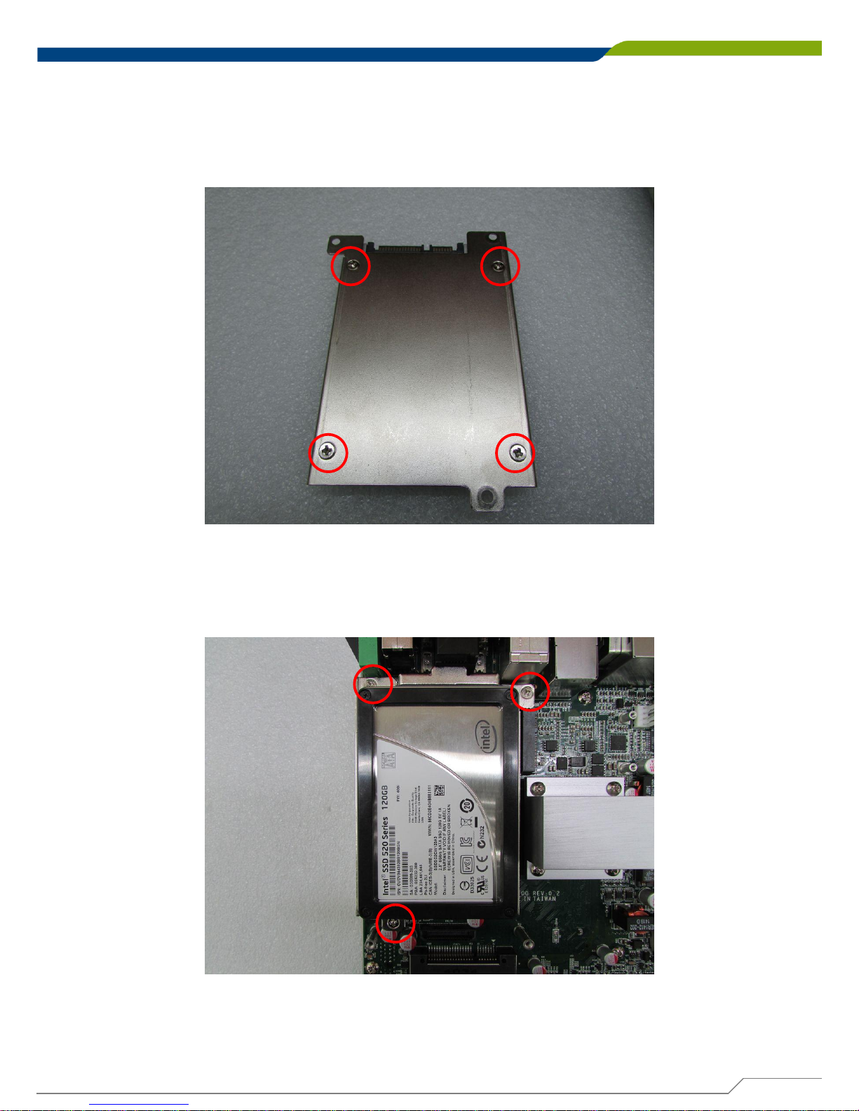
3.6 Installing a SATA Hard Drive on Upper Side
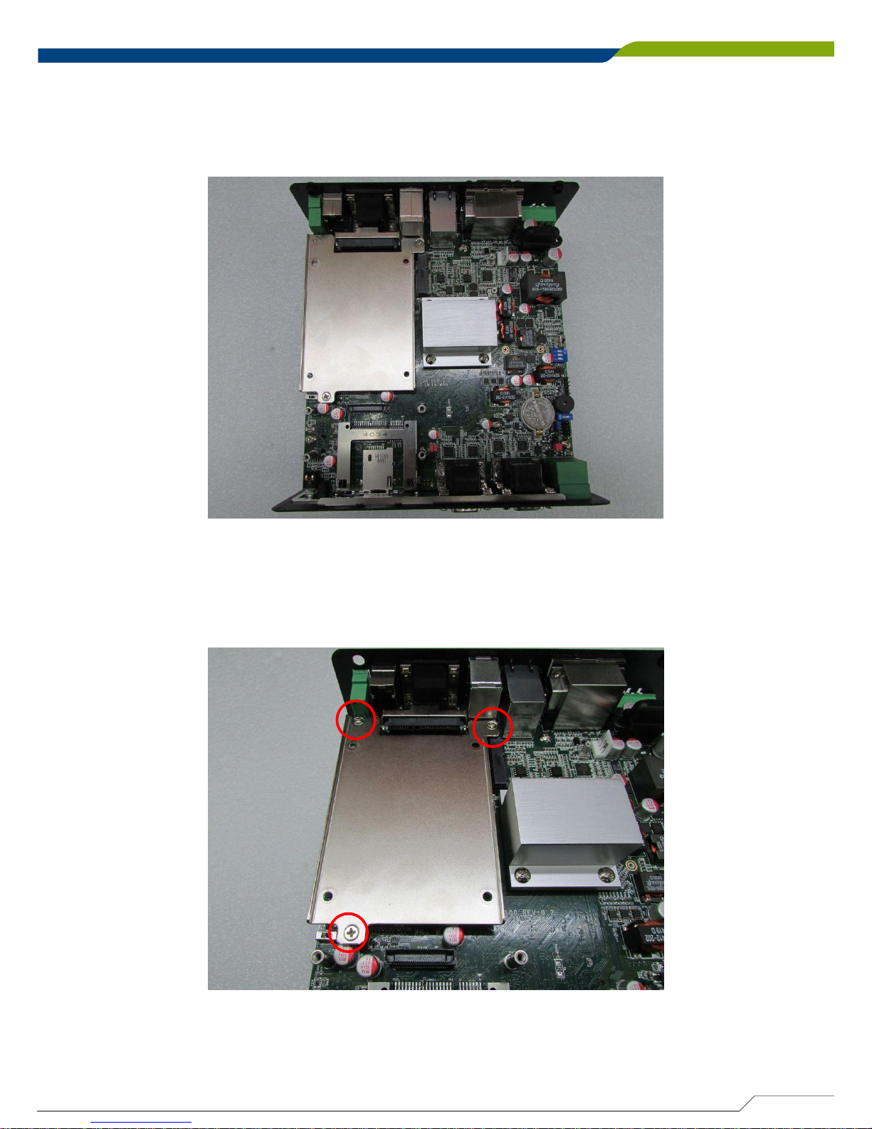
2. Loosen the 3 screws on HDD bracket and remove the bracket.
1. Flip over the body unit and place it on the table gently.
Page 60
DE-1000
Power Efficient Fanless Computer
| User’s Manual
60
Chapter 3: System Setup
4. Flip over the HDD bracket. Connect the HDD bracket to the SATA connector and fasten it
with 3 screws.
3. To have PCB side up, place the HDD bracket on it. Ensure the direction of bracket is
correct and use 4 provided screws to fasten HDD and HDD bracket together.
Page 61
DE-1000
Power Efficient Fanless Computer
| User’s Manual
61
Chapter 3: System Setup
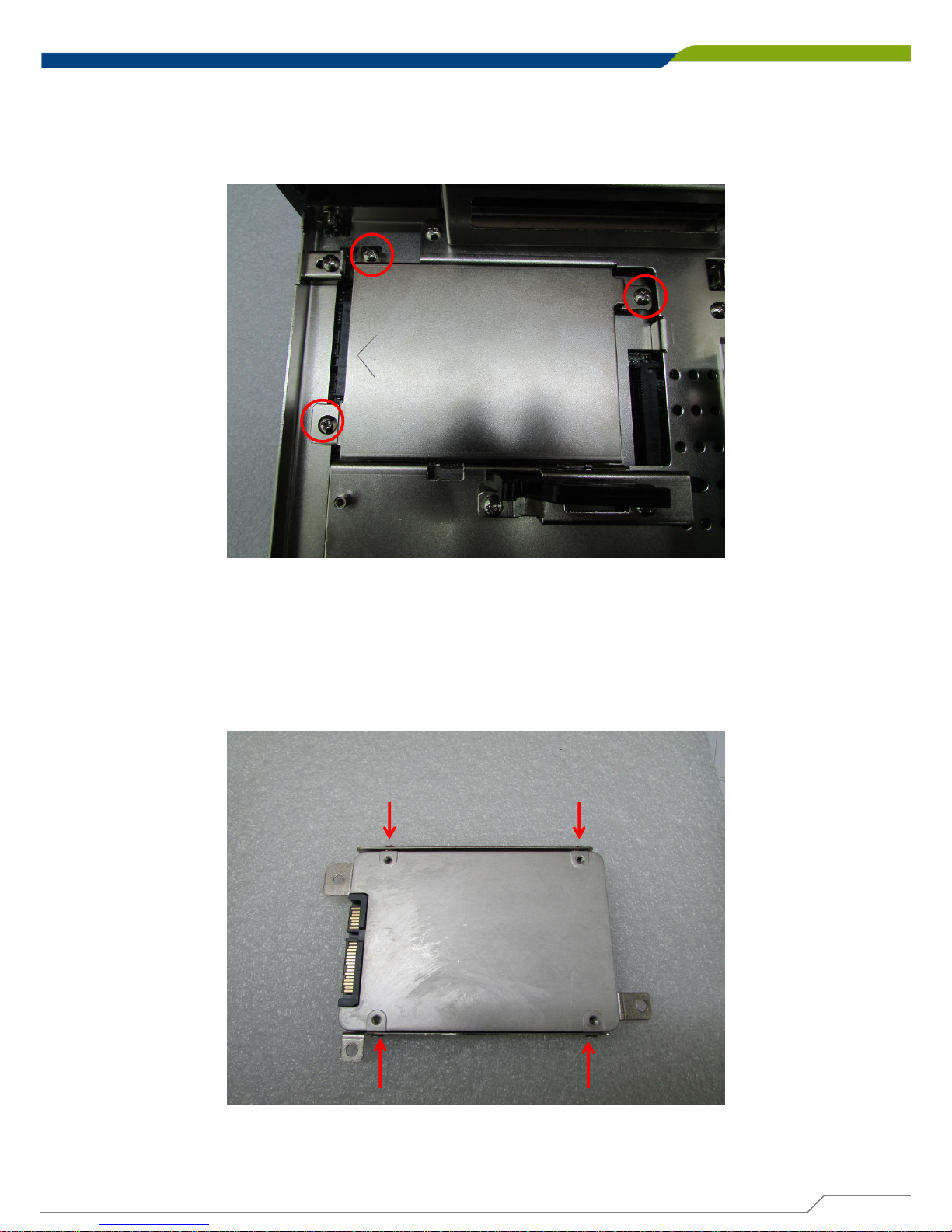
2. To have the PCB side up, and place the HDD on HDD bracket. Ensure the direction of
bracket is correct and use 4 provided screws to fasten HDD and HDD bracket together.
3.7 Installing a SATA Hard Drive on Bottom Side
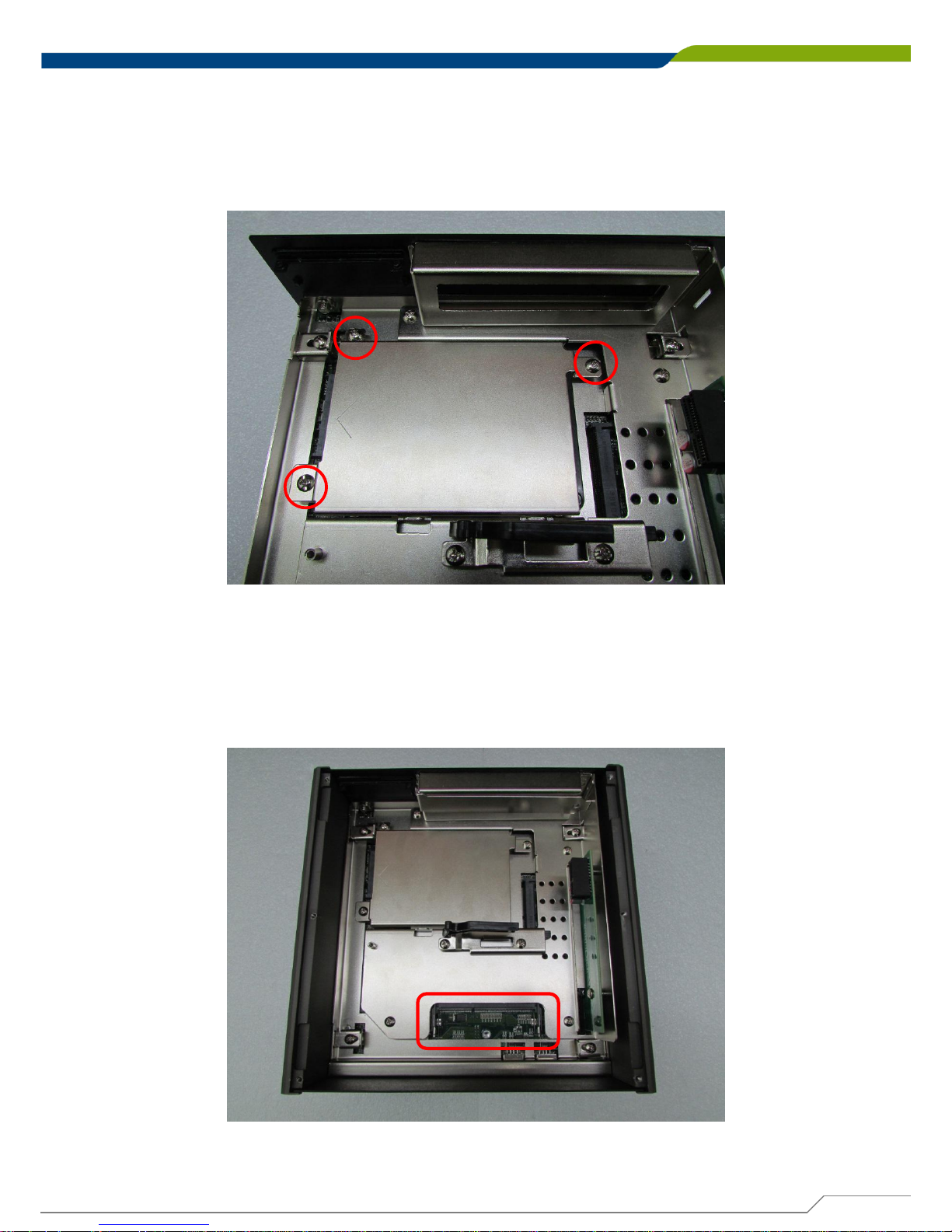
1. Flip over the body unit and locate SATA socket on the bottom side. Loosen the 3 screws on
HDD bracket and remove the bracket.
Page 62
DE-1000
Power Efficient Fanless Computer
| User’s Manual
62
Chapter 3: System Setup
3. Flip over the HDD bracket. Connect the HDD bracket to SATA connector and fasten it with
3 screws.
3.8 Installing SO-DIMM 1
1. Flip over the body unit and locate SO-DIMM socket on the bottom.
Page 63
DE-1000
Power Efficient Fanless Computer
| User’s Manual
63
Chapter 3: System Setup
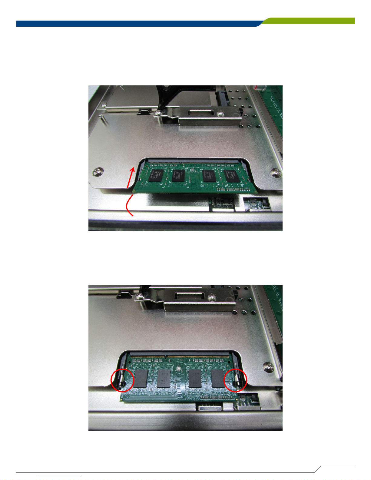
2. Tilt the SO-DIMM module at 45 degree angle and insert it to SO-DIMM socket. Be sure the
gold-plated connects to SO-DIMM slot firmly.
45°
3. Press the module down until its fixed firmly by the two locking latches on each side.
Page 64
DE-1000
Power Efficient Fanless Computer
| User’s Manual
64
Chapter 3: System Setup
3.9 Installing SO-DIMM 2
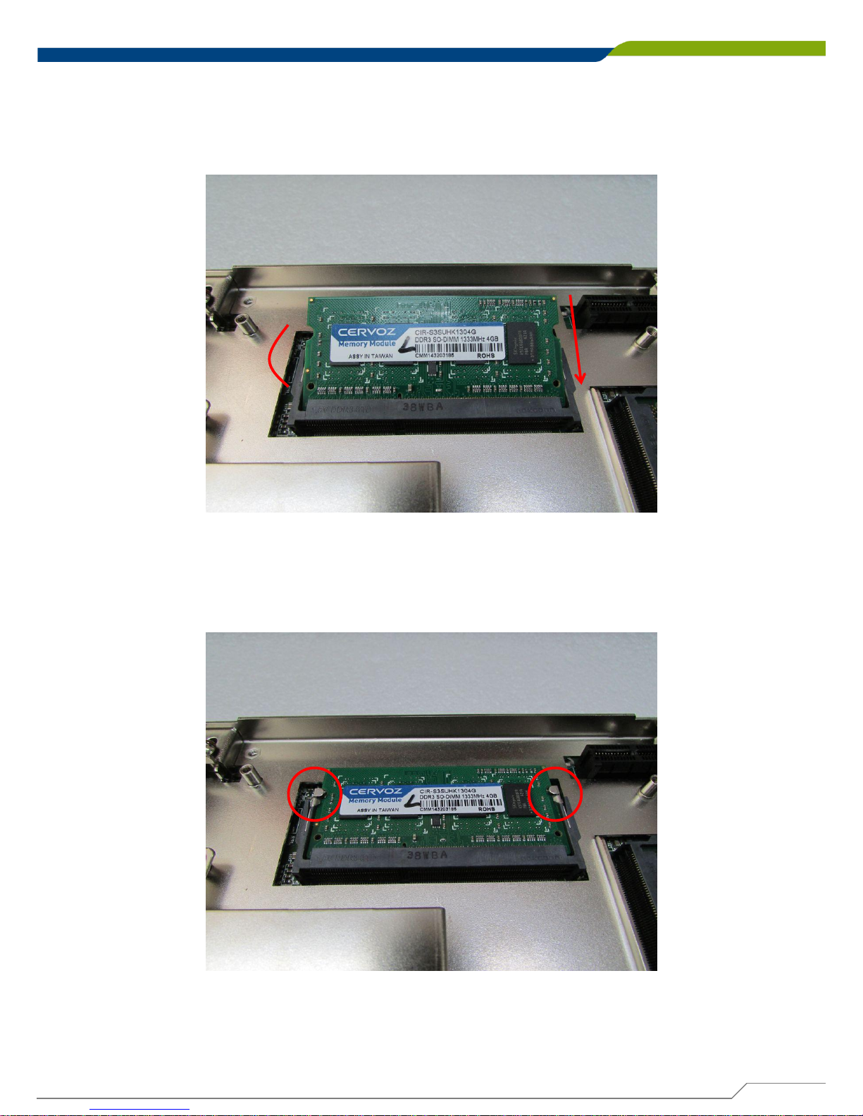
1. Flip over the body unit and locate SO-DIMM socket on the bottom. Loosen screws and take
expansion module out of system.
2. Locate SO-DIMM socket on the bottom.
Page 65
DE-1000
Power Efficient Fanless Computer
| User’s Manual
65
Chapter 3: System Setup
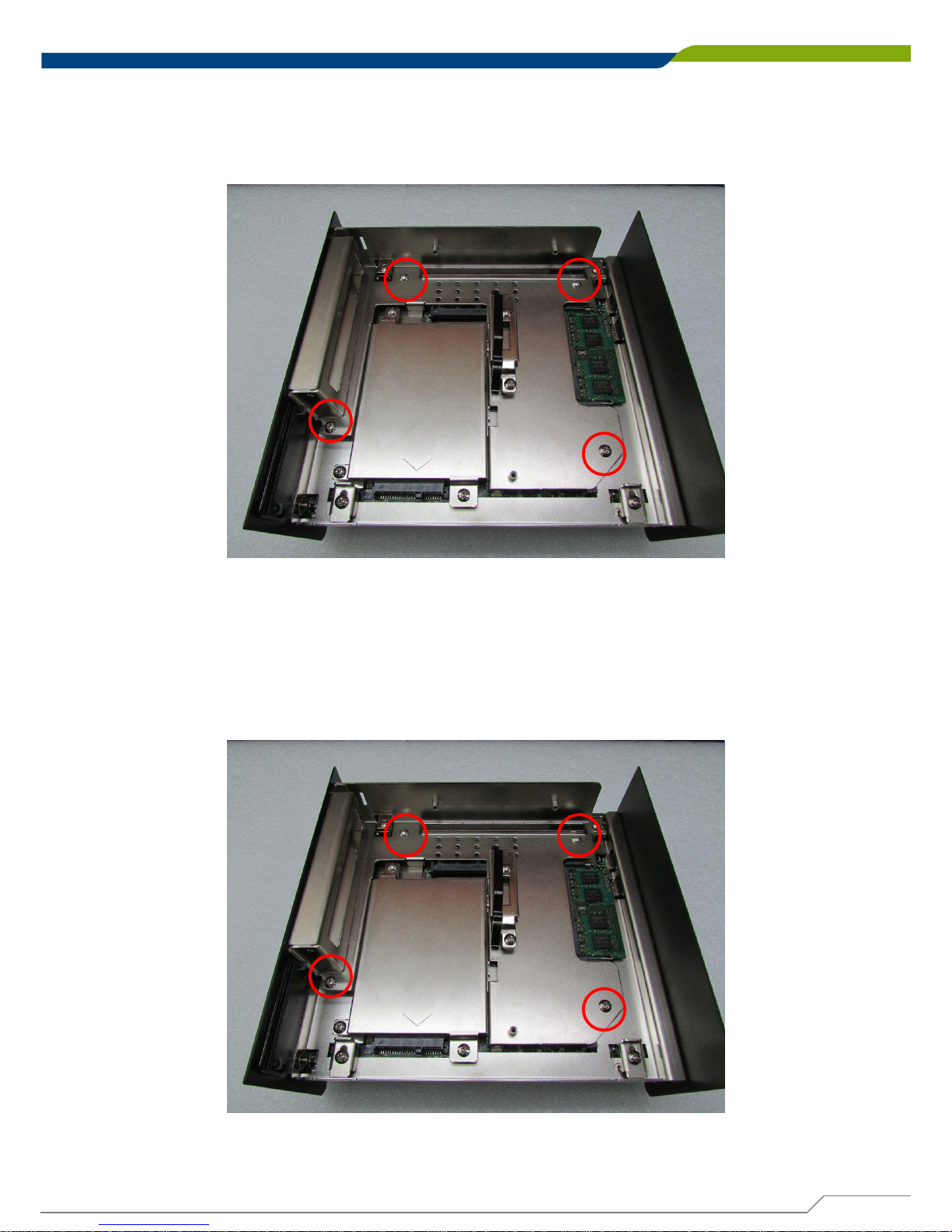
3. Tilt the SO-DIMM module at 45 degree angle and insert it to SO-DIMM socket. Be sure the
gold-plated connects to SO-DIMM socket firmly.
4. Press the module down and it’s fixed firmly by the two locking latches on each side.
45°
Page 66
DE-1000
Power Efficient Fanless Computer
| User’s Manual
66
Chapter 3: System Setup
5. Place the expansion module back to chassis and fasten it with screws afterwards.
3.10 Installing Half Size Mini PCIe Card on Bottom Side
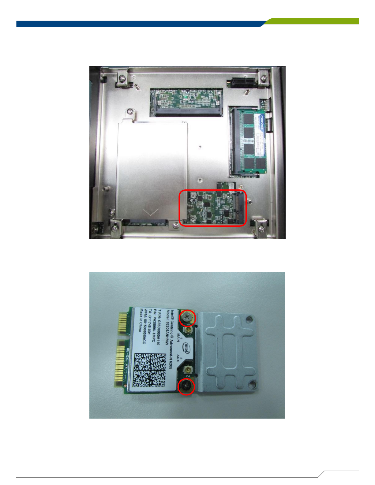
1. Flip over the body unit and locate Mini PCIe or mSATA slot on the bottom side. Loosen
screws and take expansion module out of system gently.
Page 67
DE-1000
Power Efficient Fanless Computer
| User’s Manual
67
Chapter 3: System Setup
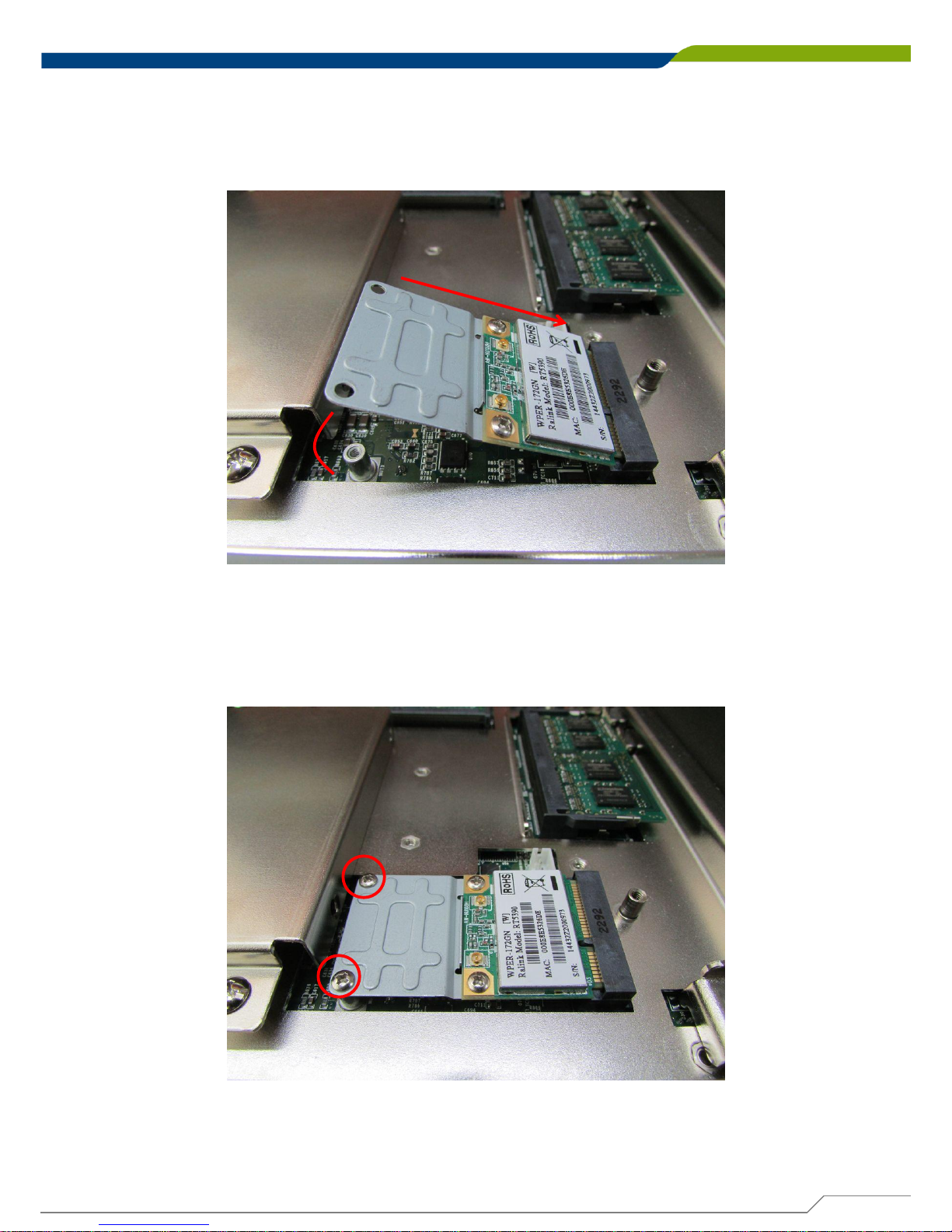
2. Locate the Mini PCIe slot.
3. Fasten the module and bracket together with 2 screws.
Page 68
DE-1000
Power Efficient Fanless Computer
| User’s Manual
68
Chapter 3: System Setup
4. Tilt the Mini PCIe module at 45 degree angle and insert it to Mini PCIe slot . Be sure the
gold-plated connects to the Mini PCIe slot firmly.
45°
5. Press down the module and use previous two screws to fix the module.
Page 69
DE-1000
Power Efficient Fanless Computer
| User’s Manual
69
Chapter 3: System Setup
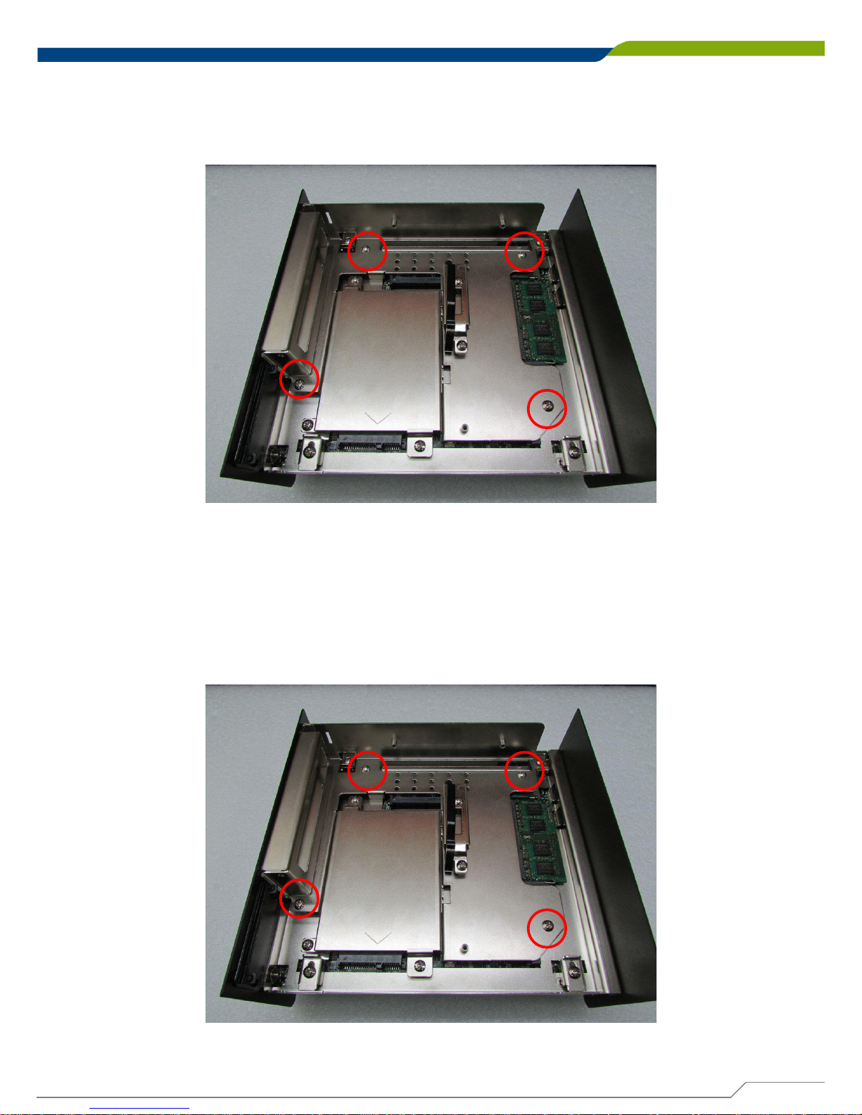
6. Place the expansion module back to chassis and fasten the screws afterwards.
3.11 Installing Full Size Mini PCIe Cards on Bottom Side
1. Flip over the body unit and locate Mini PCIe or mSATA slot on the bottom. Loosen screws
and take expansion module out of system.
Page 70
DE-1000
Power Efficient Fanless Computer
| User’s Manual
70
Chapter 3: System Setup
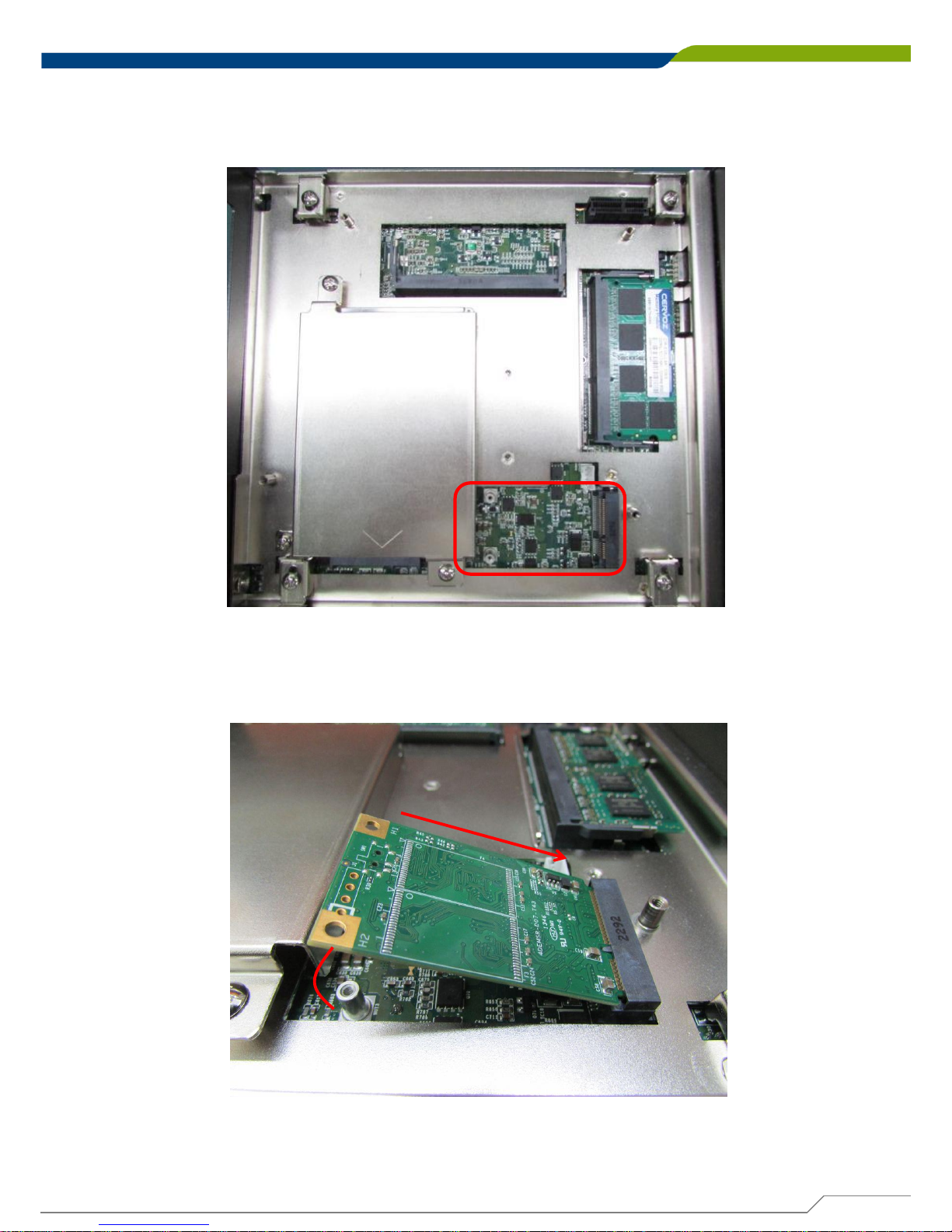
2. Locate the Mini PCIe slot.
3. Tilt the Mini PCIe or mSATA module at 45 degree angle and insert it to Mini PCIe slot. Be
sure the gold-plated connects to the Mini PCIe slot firmly.
45°
Page 71
DE-1000
Power Efficient Fanless Computer
| User’s Manual
71
Chapter 3: System Setup
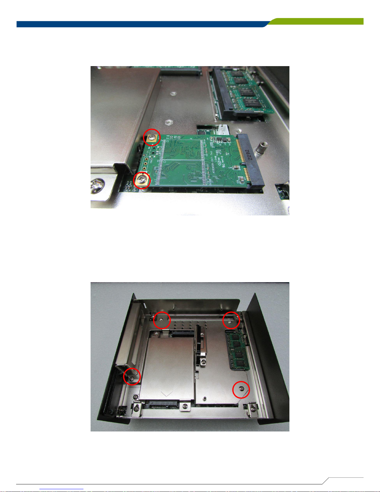
4. Press down the module and use previous two screws to fix the module.
5. Place the expansion module back to chassis and fasten the screws afterwards.
Page 72
DE-1000
Power Efficient Fanless Computer
| User’s Manual
72
Chapter 3: System Setup
3.12 Installing the PCI/PCIe Cards on Expansion Module
(DS-1001 and DS-1002 Only)
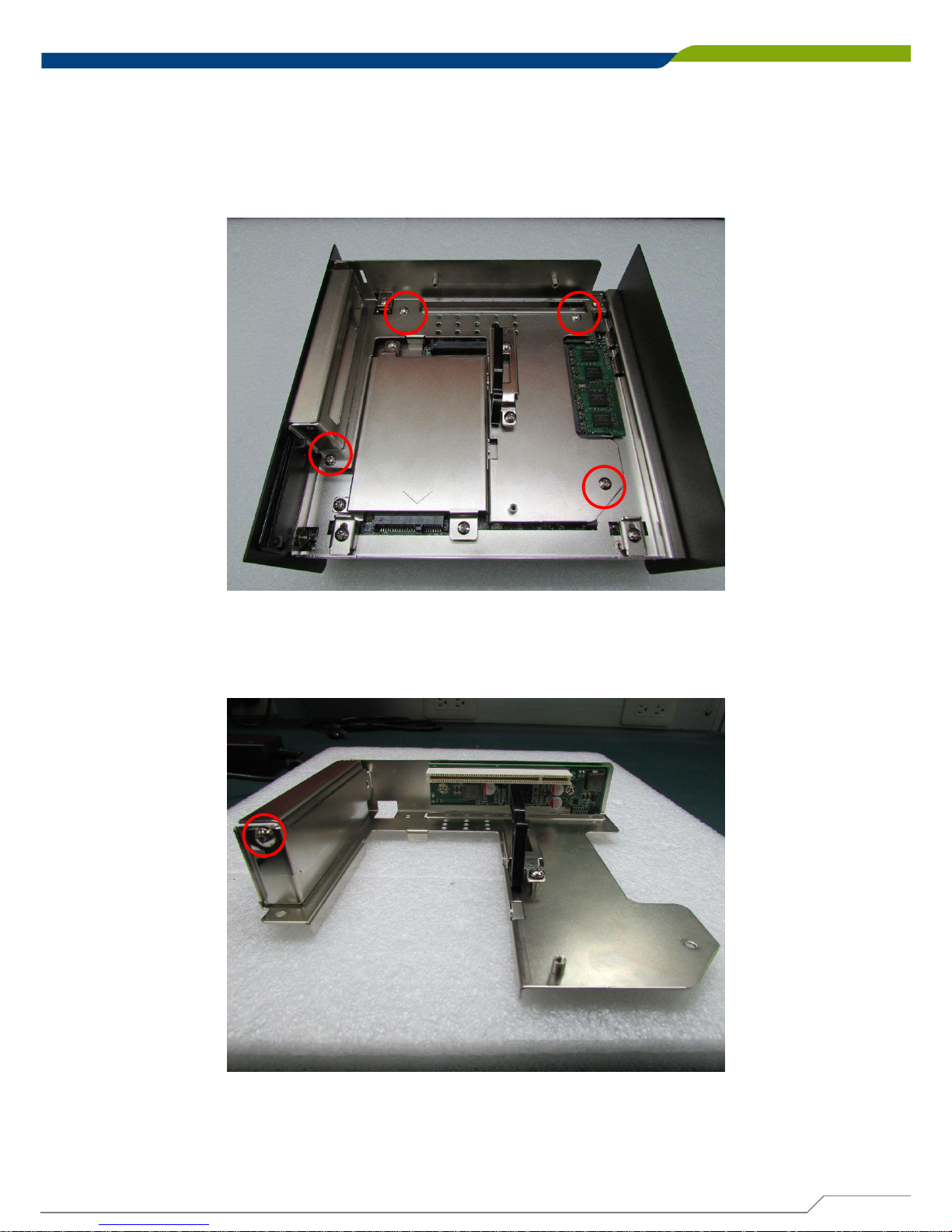
1. Locate the PCI/ PCIe expansion module, loosen screws , and take expansion module out of
system (Take DE-1001 for example).
2. Loosen the screw on PCI bracket to remove the bracket.
Page 73
DE-1000
Power Efficient Fanless Computer
| User’s Manual
73
Chapter 3: System Setup
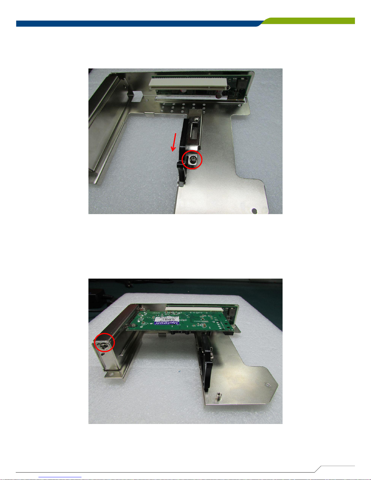
3. Loosen the screw to remove the card retainer .
4. Please check the following photos for instruction of placing expansion module. Insert the
PCI or PCIe card to the slot and fasten the screw on PCI bracket.
Page 74
DE-1000
Power Efficient Fanless Computer
| User’s Manual
74
Chapter 3: System Setup
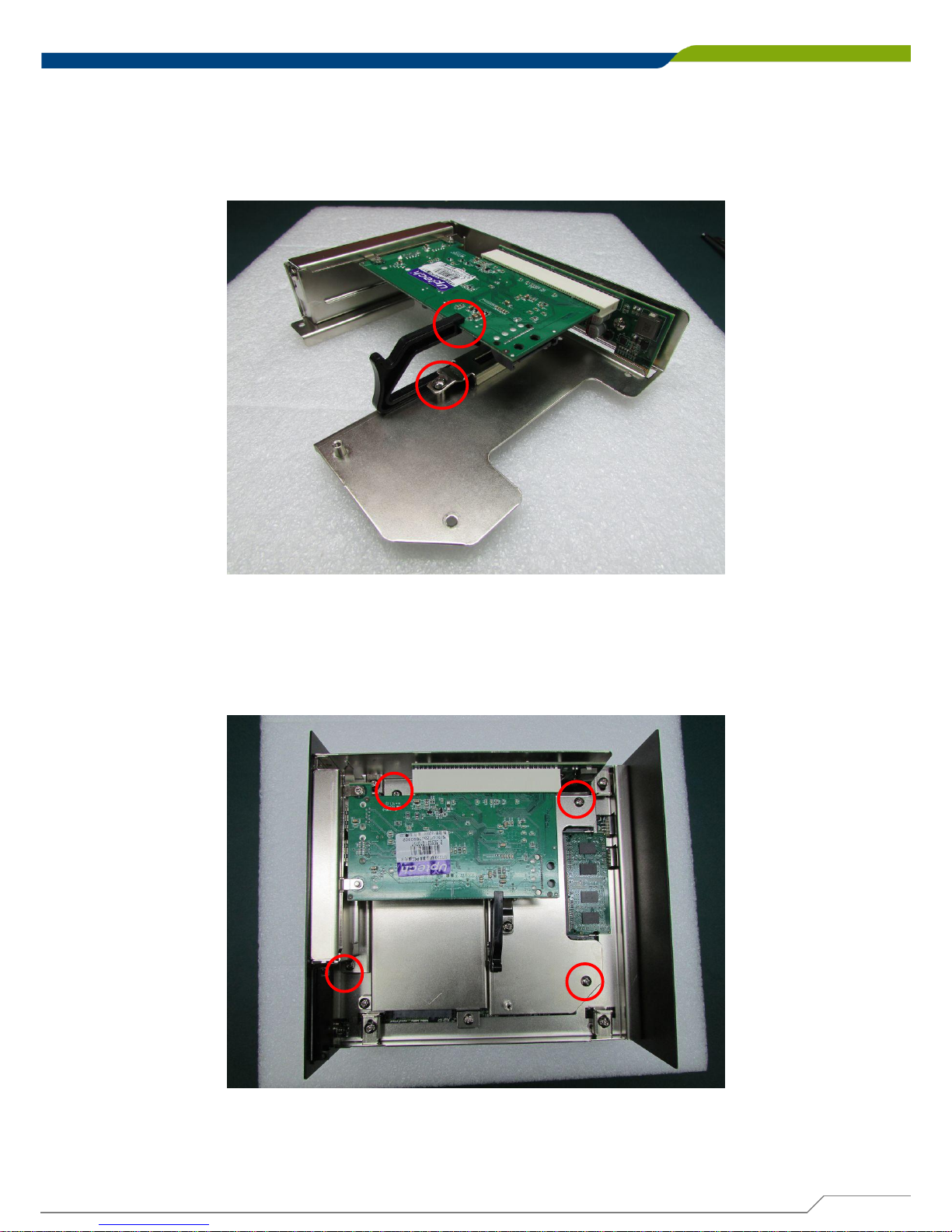
5. Before fastening the screw, you need to have the edge of PCI or PCIe module in the
grooves properly. Be sure the card retainer holds the expansion module firmly.
6. Place the expansion module back to chassis and fasten the screws afterwards.
Page 75
DE-1000
Power Efficient Fanless Computer
| User’s Manual
75
Chapter 3: System Setup
3.13 Installing the Chassis
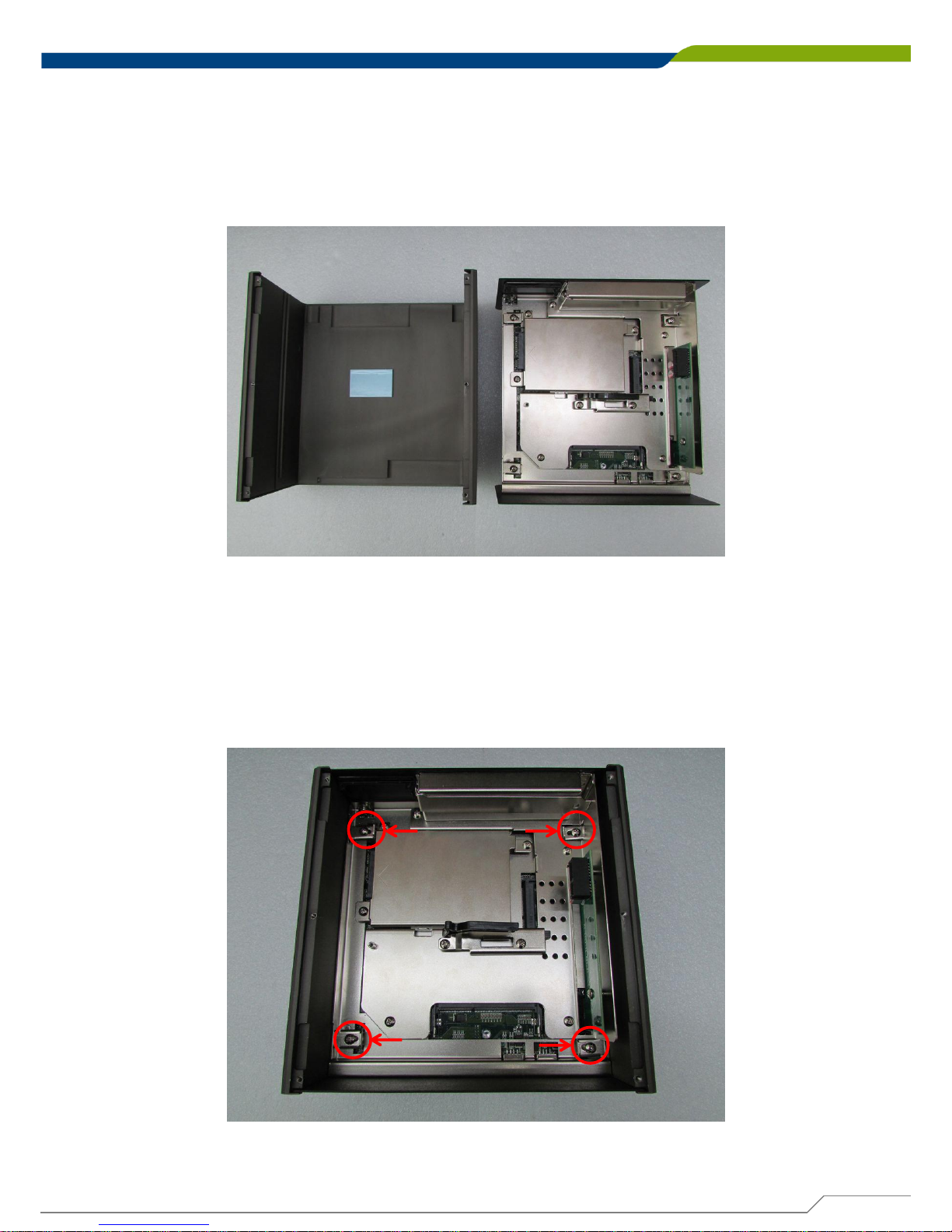
1. Be sure to align the grooves with front and rear panels. Put the cover back on and fasten
the screws to fix the cover.
2. When place back the body of unit, you need to have 4 pieces of base holders and edges of
front and rear panels are in the chassis groves in order to assemble the body onto chassis
firmly. Fasten the base holders with 4 screws afterwards.
Page 76
DE-1000
Power Efficient Fanless Computer
| User’s Manual
76
Chapter 3: System Setup
3.14 Installing the Chassis Bottom Cover
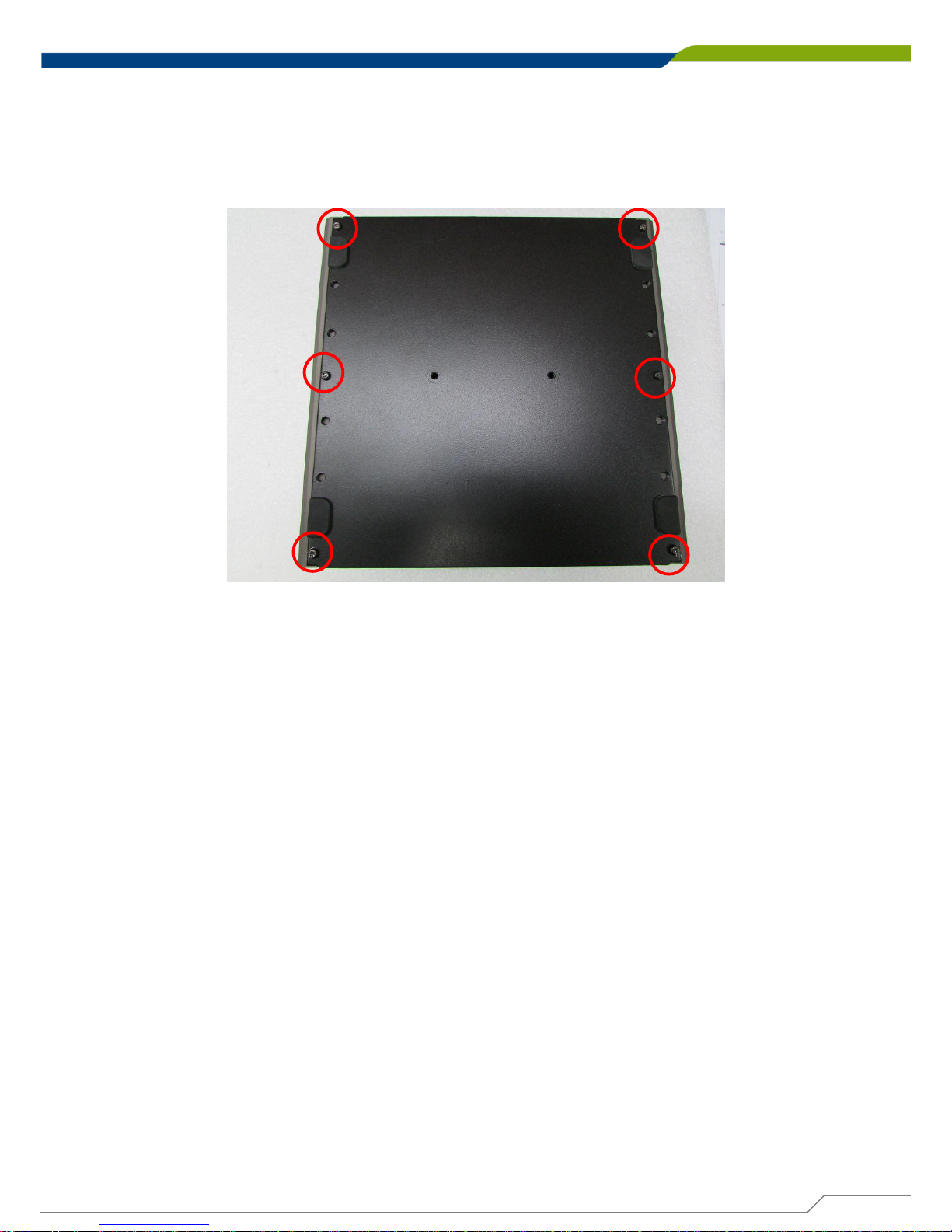
1. Be sure to align the grooves with front and rear panels. Have the bottom cover back on
the system and fasten the screws to fix the cover.
Page 77
DE-1000
Power Efficient Fanless Computer
| User’s Manual
77
Chapter 3: System Setup
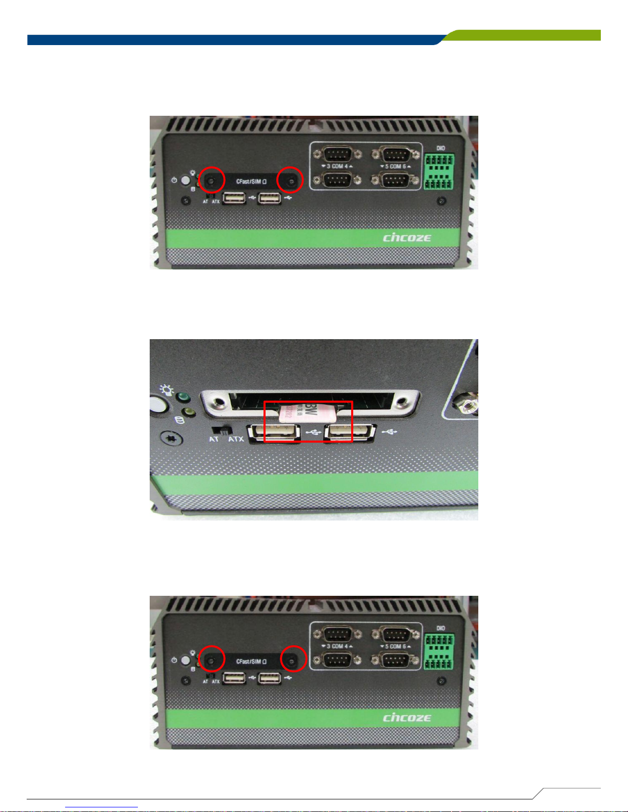
3.15 Installing a SIM Card
1. Loosen the screws in order to remove the expansion plate in the front.
2. Locate the SIM card slot to insert SIM card (according to the icon instruction aside).
3. Fasten the cover back on by using 2 screws.
Page 78
DE-1000
Power Efficient Fanless Computer
| User’s Manual
78
Chapter 3: System Setup
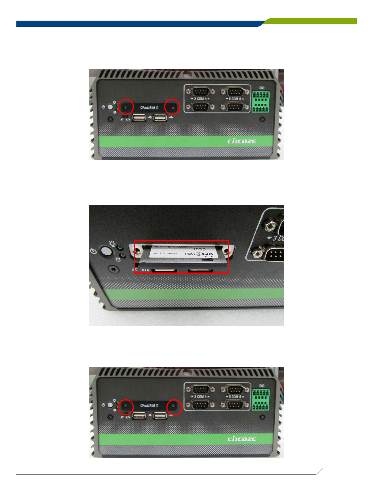
3.16 Installing a CFast Card
1. Loosen the screws in order to remove the expansion plate in the front.
2. Locate the CFast card slot to insert the CFast card.
3. Fasten the cover back on by using 2 screws.
Page 79
DE-1000
Power Efficient Fanless Computer
| User’s Manual
79
Chapter 3: System Setup
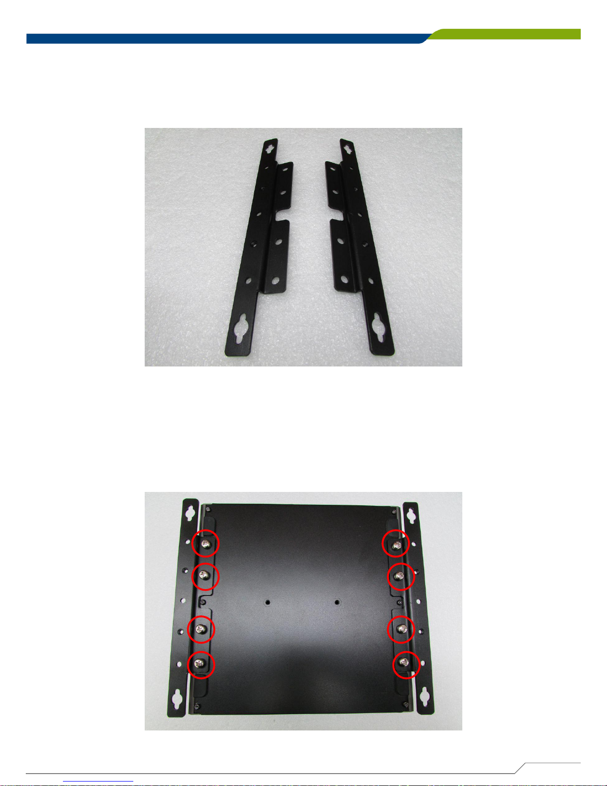
3.17 Wall Mount Brackets
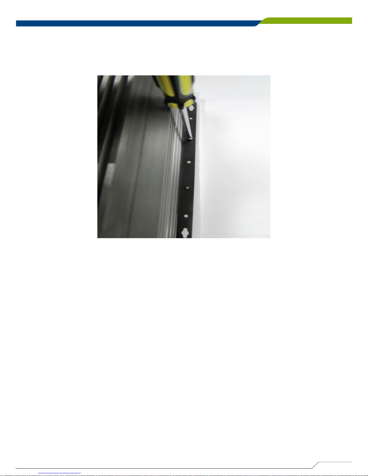
DE-1000 series offers wall mount that customers can install system on the wall in convenient
and economical ways.
1. The mounting holes are on the bottom of system. Use provided 8 screws to fasten the
brackets on each side of the system.
Page 80
DE-1000
Power Efficient Fanless Computer
| User’s Manual
80
Chapter 3: System Setup
2. Fasten the screws through the mounting hole to mount system on the wall.
Page 81

BIOS Setup
Chapter 4
Page 82
DE-1000
Power Efficient Fanless Computer
| User’s Manual
82
Chapter 4: BIOS Setup
4.1 BIOS Introduction
The BIOS (Basic Input/Output System) is a program located on a Flash Memory on the
motherboard. When you start the computer, the BIOS program will gain control. The BIOS first
operates an auto-diagnostic test called POST (power on self test) for all the necessary
hardware, it detects the entire hardware device and configures the parameters of the hardware
synchronization.
BIOS Setup
Power on the computer and by pressing <Del> immediately allows you to enter Setup. If the
message disappears before your respond and you still wish to enter Setup, restart the system
to try again by turning it OFF then ON or pressing <Ctrl>, <Alt> and <Delete> keys.
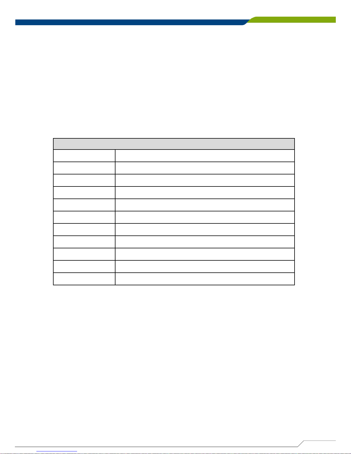
Control Keys
<
←> <→>
Move to select screen
<
↑> <↓>
Move to select item
<Esc>
Quit the BIOS Setup
<Enter>
Select item
<Page Up/+>
Increases the numeric value or makes changes
<Page Down/
->
Decreases the numeric value or makes changes
<Tab>
Select setup fields
<F1>
General help
<F2>
Previous value
<F3>
Load Optimized defaults
<F10>
Save configuration and Exit
Main Menu
The main menu lists the setup functions you can make changes to. You can use the arrow keys
( ↑↓ ) to select the item. The on-line description of the highlighted setup function is displayed at
the bottom of the screen.
Sub-Menu
If you find a right pointer symbol appears to the left of certain fields that means a sub-menu can
be launched from this field. A sub-menu contains additional options for a field parameter. You
can use arrow keys ( ↑↓ ) to highlight the field and press <Enter> to call up the sub-menu. Then
you can use the control keys to enter values and move from field to field within a sub-menu. If
you want to return to the main menu, just press the <Esc >.
Page 83
DE-1000
Power Efficient Fanless Computer
| User’s Manual
83
Chapter 4: BIOS Setup
4.2 Main Setup
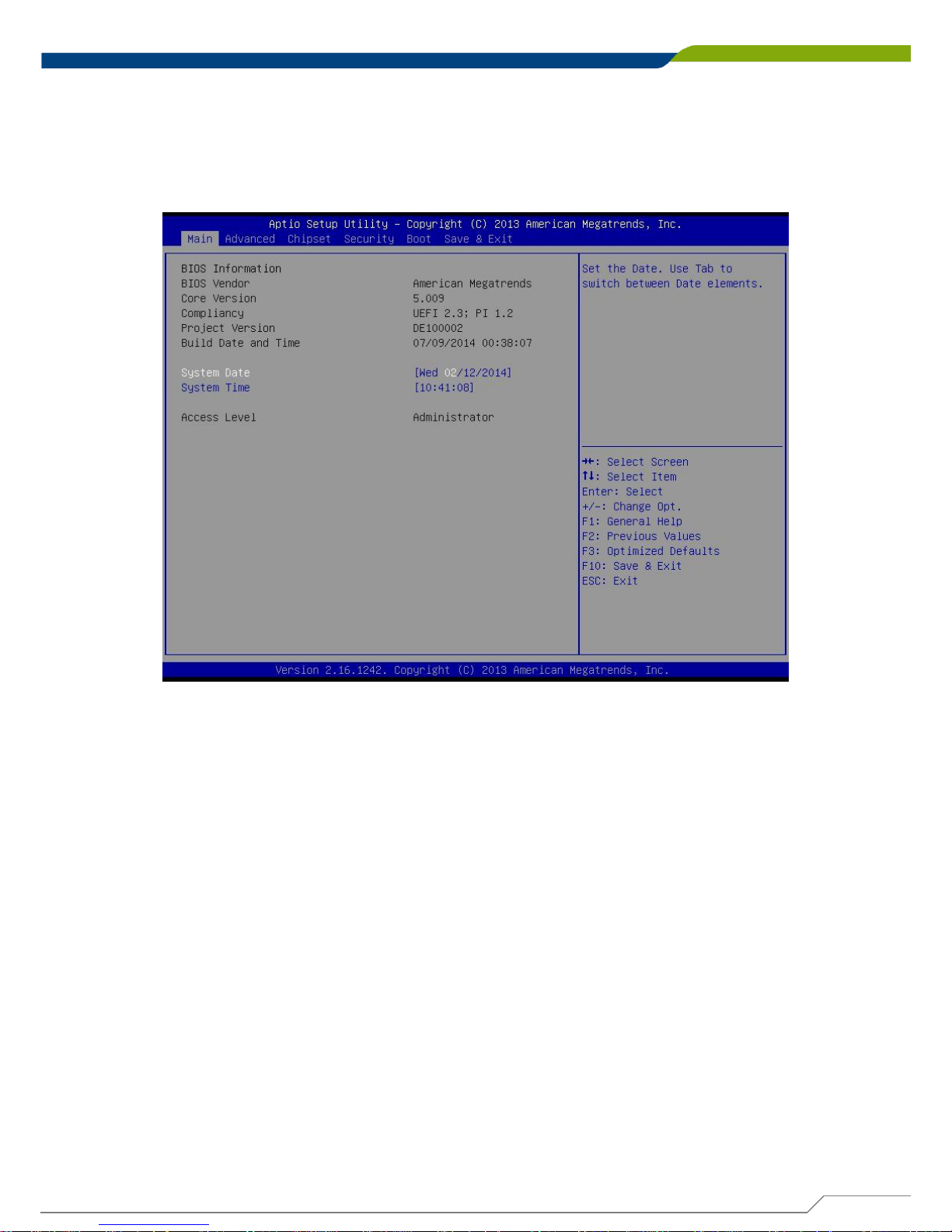
Press <Del> to enter BIOS CMOS Setup Utility, the Main Menu (as shown below) will appears
on the screen. Use arrow keys to move among the items and press <Enter> to accept or enter
a sub-menu.
4.2.1 System Date
Set the date. Please use <Tab> to switch between data elements.
4.2.2 System Time
Set the time. Please use <Tab> to switch between time elements.
Page 84
DE-1000
Power Efficient Fanless Computer
| User’s Manual
84
Chapter 4: BIOS Setup
4.3 Advanced Setup
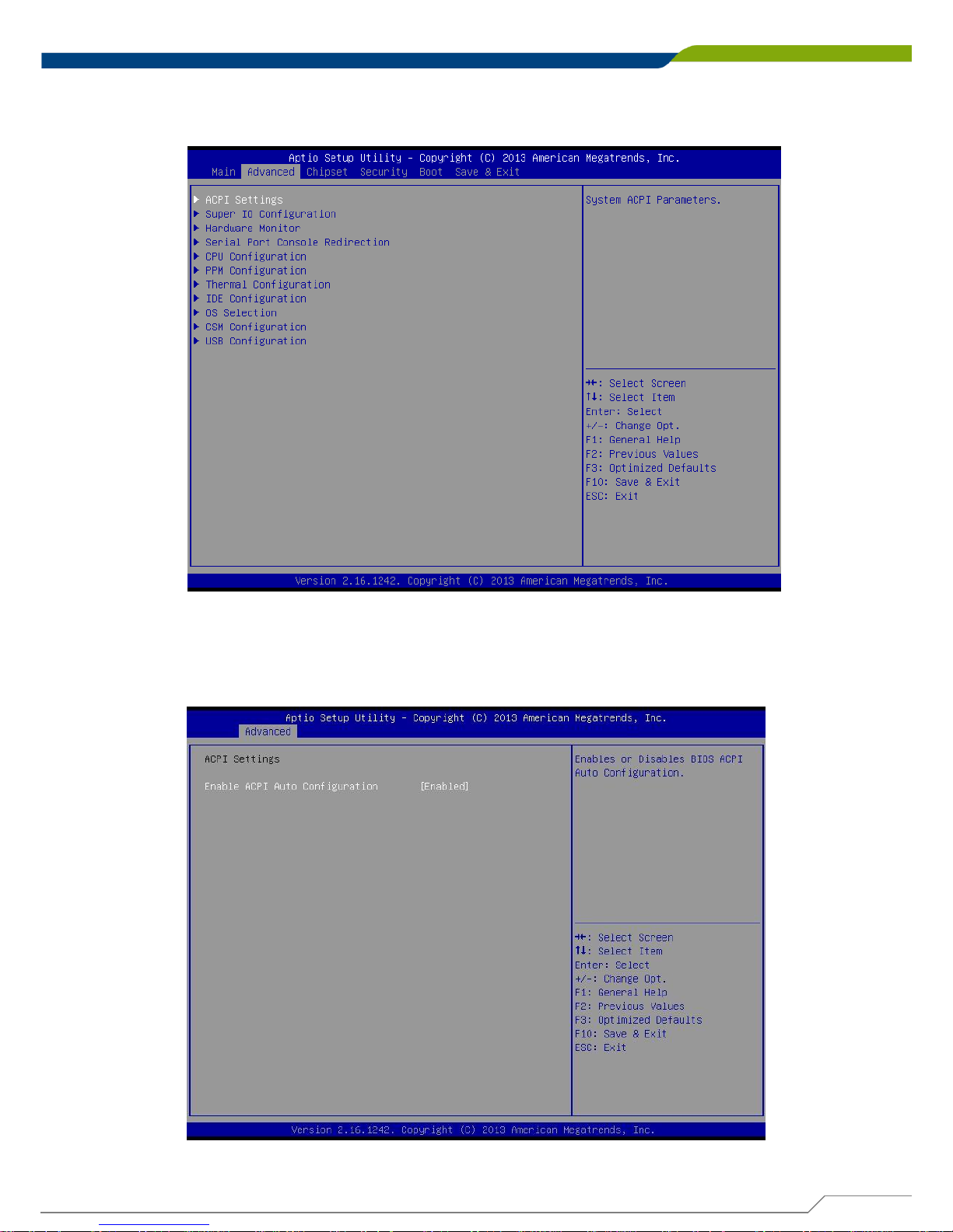
4.3.1 ACPI Settings
Enable or disable BIOS ACPI Auto Configuration.
Page 85
DE-1000
Power Efficient Fanless Computer
| User’s Manual
85
Chapter 4: BIOS Setup
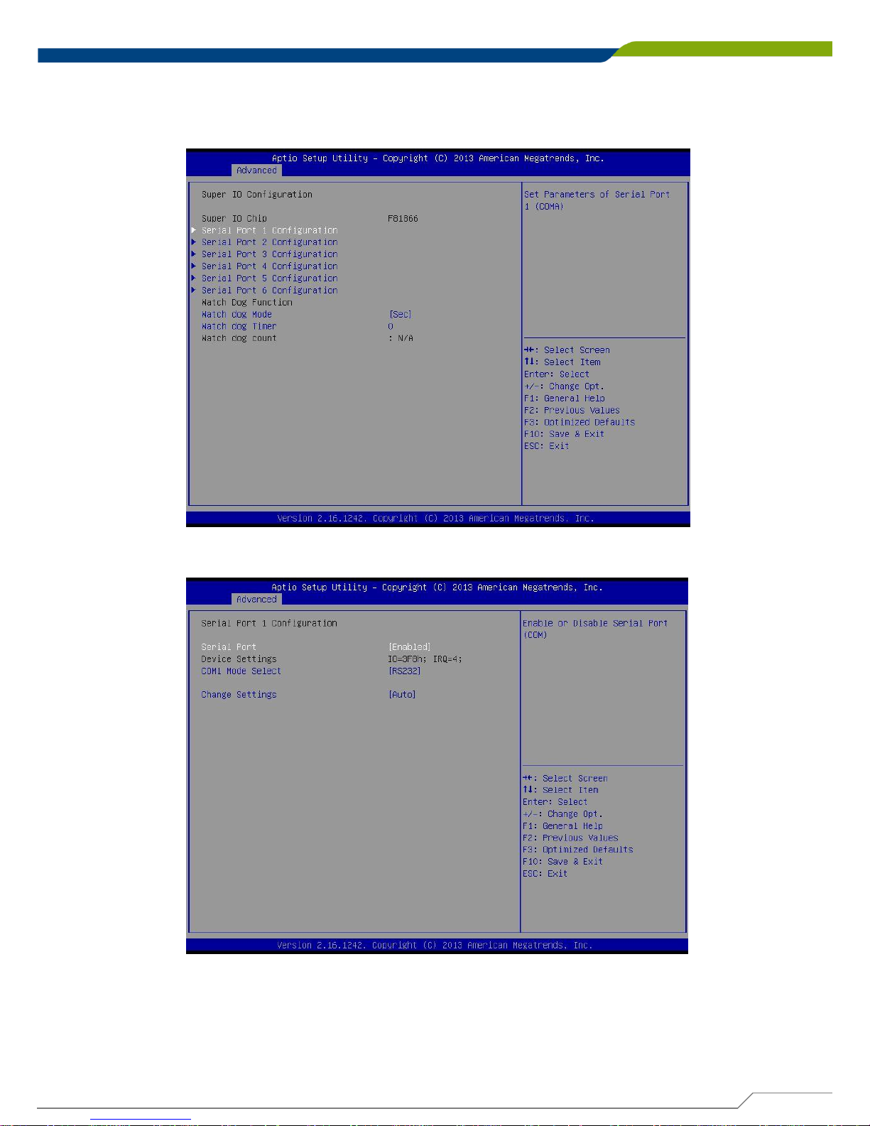
4.3.2 Super IO Configuration
You can use this screen to select options for the Super IO Configuration, and change the value
of the selected option.
■ Serial Port 1 Configuration
Serial Port
This item will allow users to enable or disable serial port.
COM1 Mode Select
Change the Serial interface. Select <RS232> ,<RS422> or <RS485> interface.
Change Settings
This setting is used to change the address & IRQ settings of the specified serial port.
Page 86
DE-1000
Power Efficient Fanless Computer
| User’s Manual
86
Chapter 4: BIOS Setup
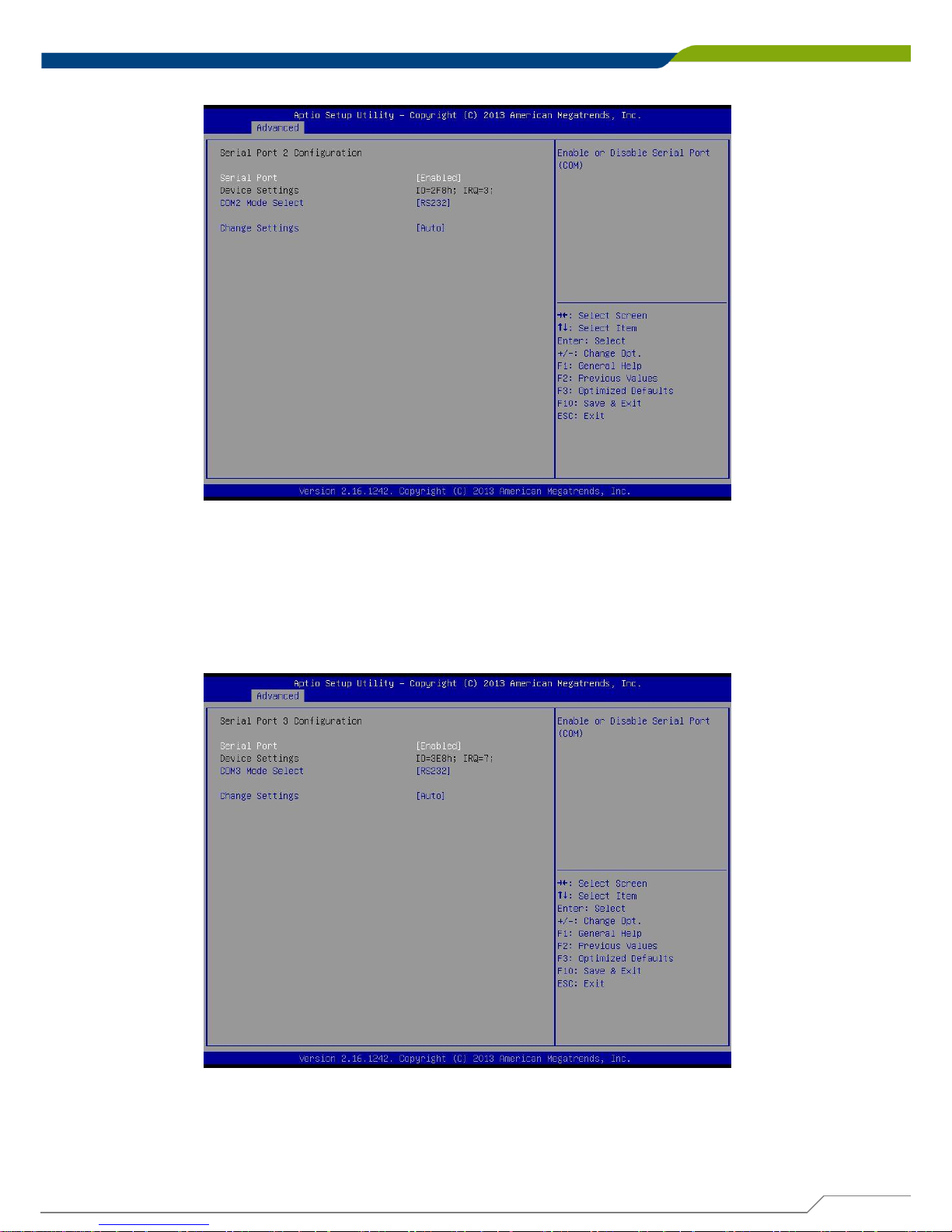
■ Serial Port 2 Configuration
Serial Port
This item will allow users to enable or disable serial port.
COM2 Mode Select
Change the Serial interface. Select <RS232> ,<RS422> or <RS485> interface.
Change Settings
This setting is used to change the address & IRQ settings of the specified serial port.
■ Serial Port 3 Configuration
Serial Port
This item will allow users to enable or disable serial port.
COM3 Mode Select
Change the Serial interface. Select <RS232> ,<RS422> or <RS485> interface.
Change Settings
This setting is used to change the address & IRQ settings of the specified serial port.
Page 87
DE-1000
Power Efficient Fanless Computer
| User’s Manual
87
Chapter 4: BIOS Setup
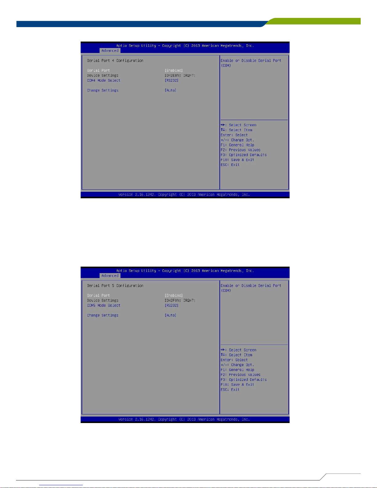
■ Serial Port 4 Configuration
Serial Port
This item will allow users to enable or disable serial port.
COM4 Mode Select
Change the Serial interface. Select <RS232> ,<RS422> or <RS485> interface.
Change Settings
This setting is used to change the address & IRQ settings of the specified serial port.
■ Serial Port 5 Configuration
Serial Port
This item will allow users to enable or disable serial port.
COM5 Mode Select
Change the Serial interface. Select <RS232> ,<RS422> or <RS485> interface.
Change Settings
This setting is used to change the address & IRQ settings of the specified serial port.
Page 88
DE-1000
Power Efficient Fanless Computer
| User’s Manual
88
Chapter 4: BIOS Setup
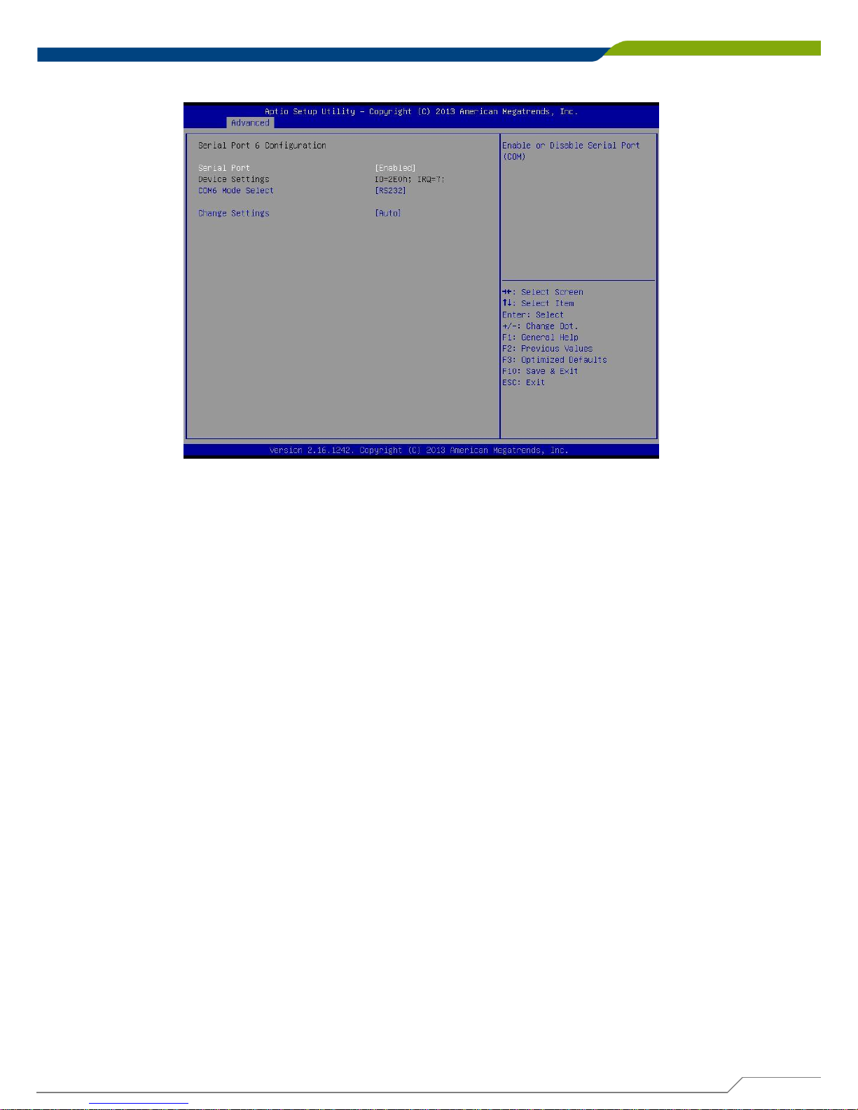
■ Serial Port 6 Configuration
Serial Port
This item will allow users to enable or disable serial port.
COM6 Mode Select
Change the Serial interface. Select <RS232> ,<RS422> or <RS485> interface.
Change Settings
This setting is used to change the address & IRQ settings of the specified serial port.
Watch Dog Function
You can setup the system watch-dog timer, a hardware timer that generates a reset when
the software that it monitors does not respond as expected each time the watch dog polls
it.
Watch Dog Mode
Change the Watch dog mode. Select <Sec> or <Min> mode.
Watch Dog Timer
User can set a value in the range of 0 to 255.
Page 89
DE-1000
Power Efficient Fanless Computer
| User’s Manual
89
Chapter 4: BIOS Setup
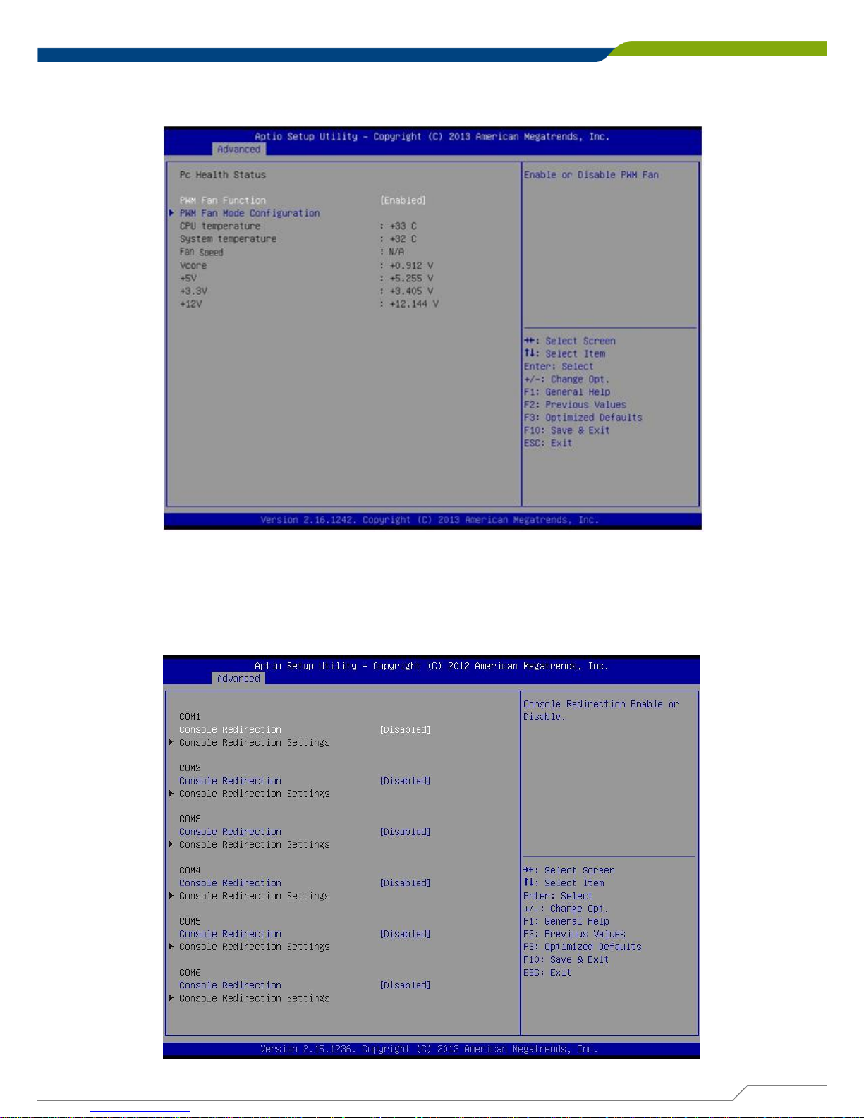
4.3.3 Hardware Monitor
These items display the current status of all monitored hardware devices/ components such as
voltages and temperatures.
■ PWM Fan Function
This item will allow users to enable or disable PWM Fan.
■ PWM Fan Mode Configuration
PWM Fan Duty
This item allows users to change the PWM Fan duty.
4.3.4 Serial Port Console Redirection
■ Console Redirection
This item allows users to enable or disable console redirection.
Page 90
DE-1000
Power Efficient Fanless Computer
| User’s Manual
90
Chapter 4: BIOS Setup
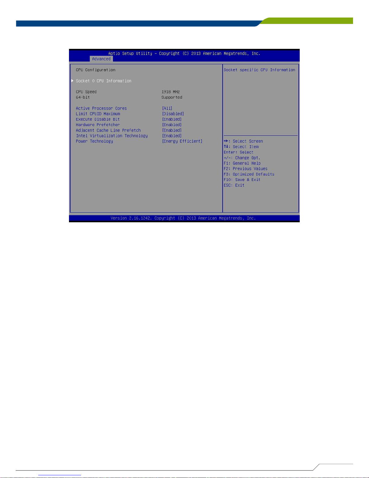
4.3.5 CPU Configuration
■ Socket 0 CPU Information
This section provides information on your CPU, frequency, and cache memory.
■ Active Processor Cores
Change the active processor cores. Select <All> or <1> mode.
■ Limit CPUID Maximum
Allows user to determine whether to limit CPUID maximum value. Set this item to
Disabled: For Windows XP operating system.
Enabled: For legacy operating system such as Windows NT4.0. (Default: Disabled)
■ Execute Disable Bit
Enables or disables Intel Execute Disable Bit function.
■ Hardware Prefetcher
Enables or disables L2 Cache Hardware Prefetcher.
■ Adjacent Cache Line Prefetch
Enables or disables L2 prefetching of adjacent cache lines.
■ Intel Virtualization Technology
Enables or disables Intel Virtualization Technology. Virtualization enhanced by Intel
Virtualization Technology will allow a platform to run multiple operating systems and
applications in independent partitions. With virtualization, one computer system can
function as multiple virtual systems.
■ Power Technology
Allows user to configure Intel power management features.
Page 91
DE-1000
Power Efficient Fanless Computer
| User’s Manual
91
Chapter 4: BIOS Setup
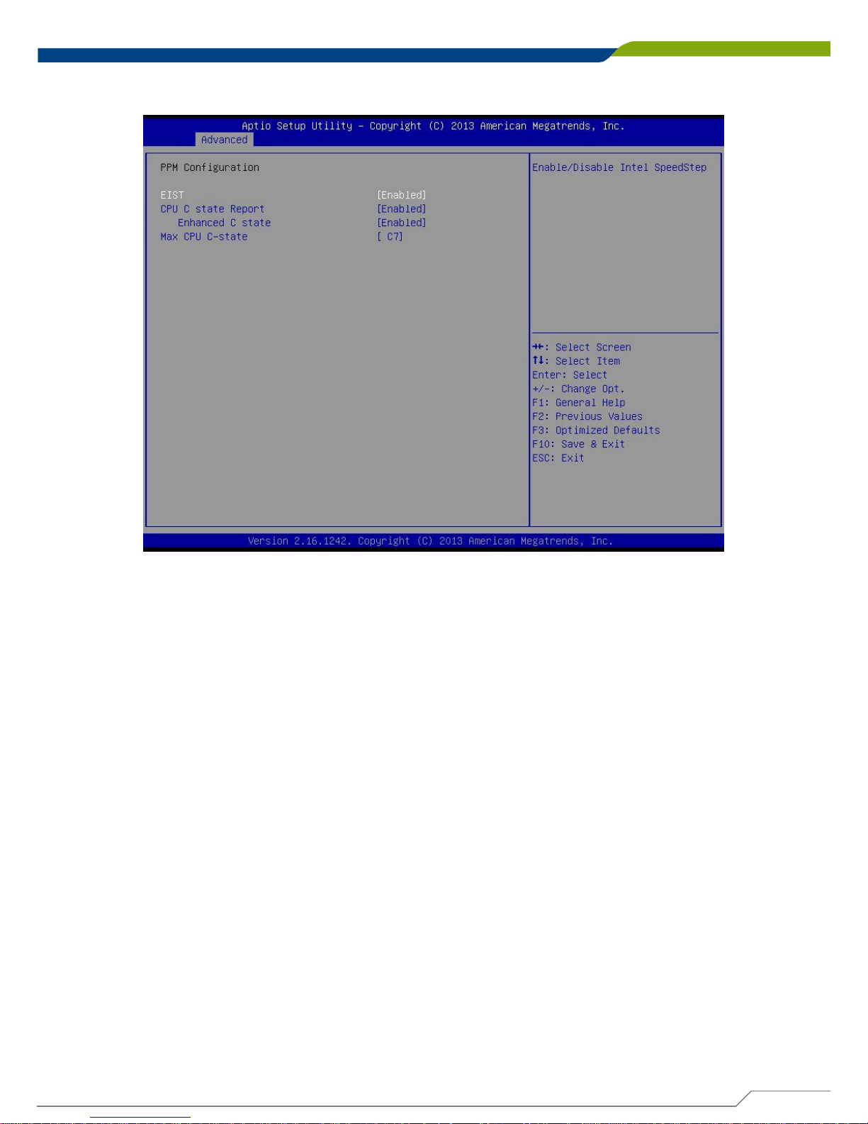
4.3.6 PPM Configuration
■ EIST
Enable or disable Intel SpeedStep.
■ CPU C state Report
Enables or disables support for CPU's power-saving functions.
■ Enhanced C state
Enables or disables Intel CPU Enhanced Halt (C1E) function, a CPU power-saving function
in system halt state. When enabled, the CPU core frequency and voltage will be reduced
during system halt state to decrease power consumption. This item is configurable only
when CPU C state Report is enabled.
■ Max CPU C-state
Allows user to determine the maximum C state that the CPU will support.
Page 92
DE-1000
Power Efficient Fanless Computer
| User’s Manual
92
Chapter 4: BIOS Setup
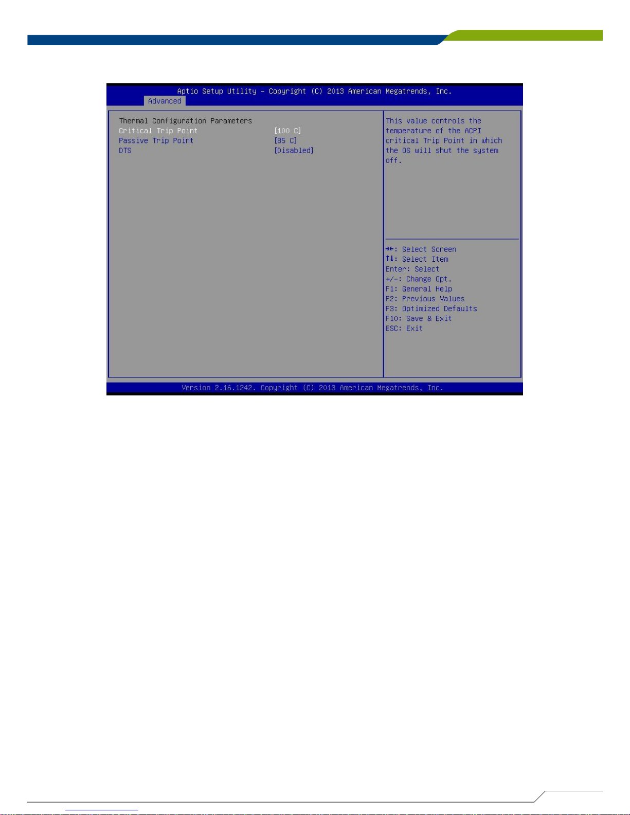
4.3.7 Thermal Configuration
■ Critical Trip Point
Allows user to set the CPU temperature threshold. If the CPU temperature reaches this
value, the operating system will shut down the system. This item is configurable only when
DTS is enabled.
■ Passive Trip Point
Allows user to set the CPU temperature threshold. If the CPU temperature reaches this
value, the CPU frequency will be automatically reduced. This item is configurable only
when DTS is enabled.
■ DTS
Enables or disables the CPU overheating protection function. (Default: Disabled)
Page 93
DE-1000
Power Efficient Fanless Computer
| User’s Manual
93
Chapter 4: BIOS Setup
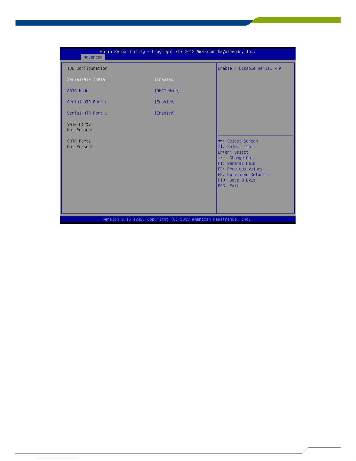
4.3.8 IDE Configuration
■ Serial-ATA (SATA)
This item will allow users to enable or disable Serial ATA.
■ SATA Mode
This item will allow users to select IDE or AHCI Mode.
■ Serial – ATA Port 0
This item will allow users to enable or disable Serial-ATA Port 0.
■ Serial – ATA Port 1
This item will allow users to enable or disable Serial-ATA Port 1.
Page 94
DE-1000
Power Efficient Fanless Computer
| User’s Manual
94
Chapter 4: BIOS Setup
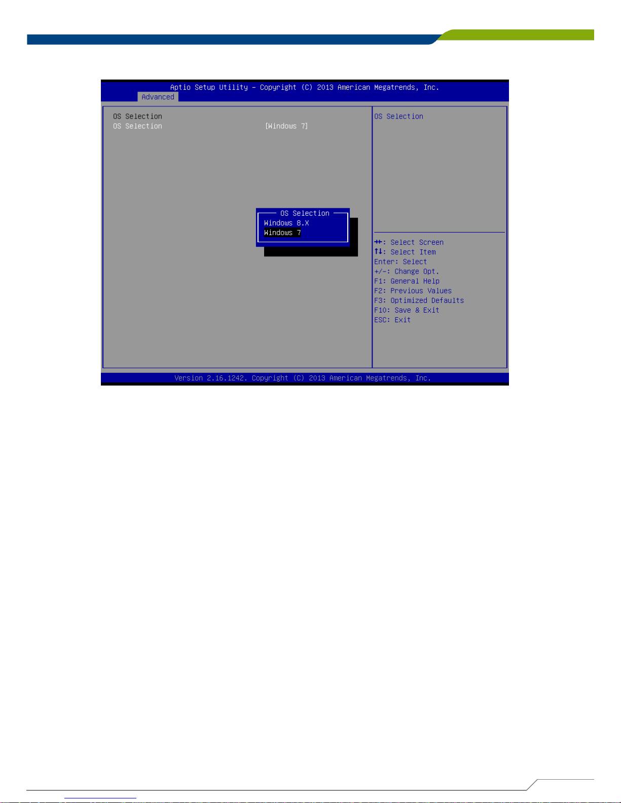
4.3.9 OS Selection
■ OS Selection
This item will allow users to select Windows 8.X or Windows 7 OS.
Page 95
DE-1000
Power Efficient Fanless Computer
| User’s Manual
95
Chapter 4: BIOS Setup
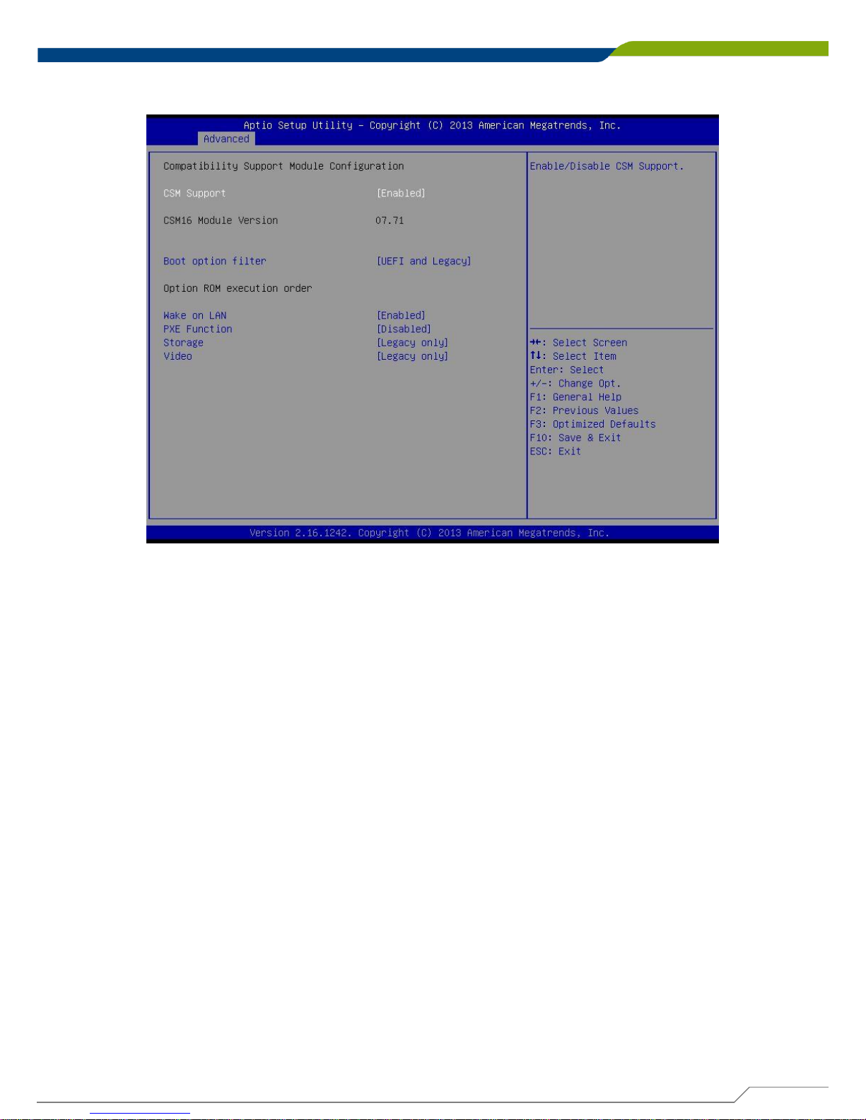
4.3.10 CSM (Compatibility Support Module) Configuration
■ CSM Support
Enables or disables UEFI CSM (Compatibility Support Module) to support a legacy PC boot
process.
■ Boot option filter
Allows user to select which type of operating system to boot.
UEFI and Legacy: Allows booting from operating systems that support legacy option ROM
or UEFI option ROM.
Legacy only: Allows booting from operating systems that only support legacy option ROM.
UEFI only: Allows booting from operating systems that only support UEFI option ROM.
This item is configurable only when CSM Support is set to Enabled.
■ Wake on LAN
This item will allow users to enable or disable wake on LAN function.
■ PXE Function
This item will allow users to enable or disable PXE function.
■ Storage
Allows user to select whether to enable the UEFI or legacy option ROM for the storage
device controller.
Do not launch: Disables option ROM.
UEFI only: Enables UEFI option ROM only.
Legacy only: Enables legacy option ROM only.
■ Video
Allows user to select whether to enable the UEFI or legacy option ROM for the storage
device controller.
Do not launch: Disables option ROM.
UEFI only: Enables UEFI option ROM only.
Legacy only: Enables legacy option ROM only.
Page 96
DE-1000
Power Efficient Fanless Computer
| User’s Manual
96
Chapter 4: BIOS Setup
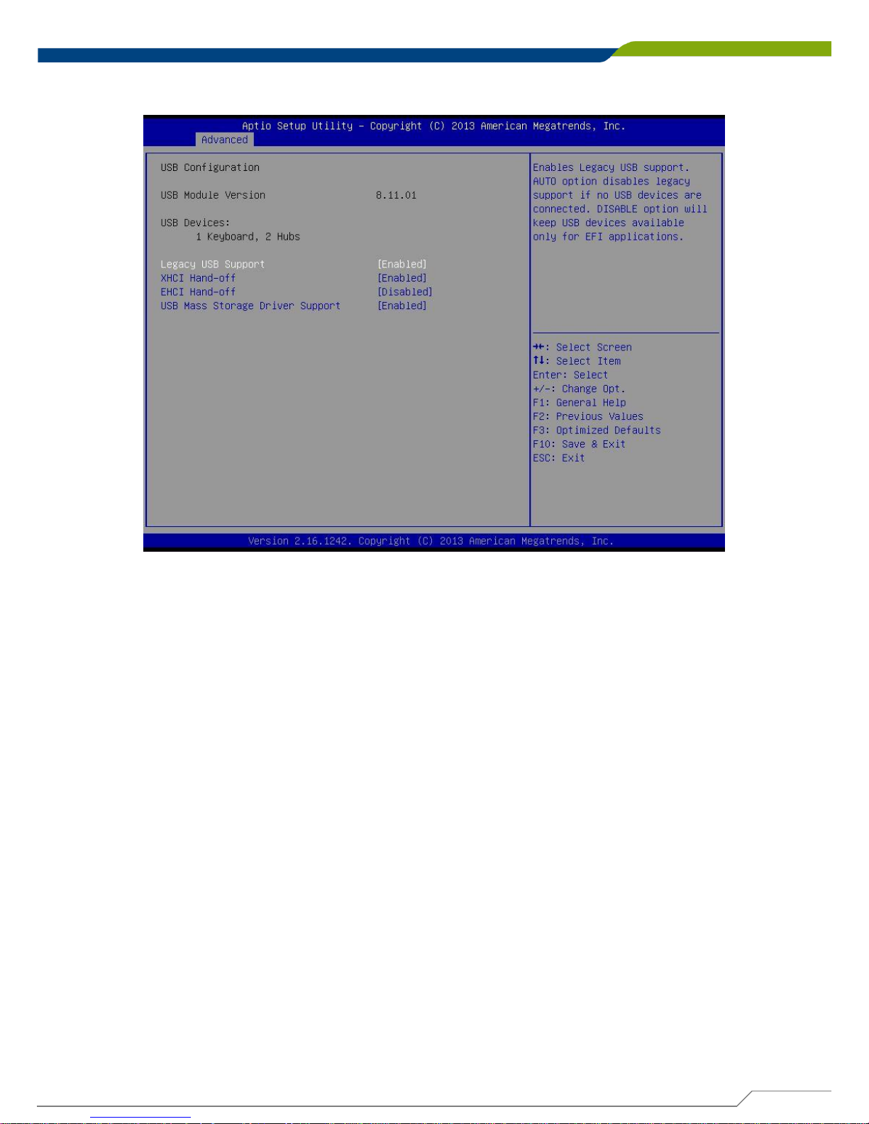
4.3.11 USB Configuration
■ Legacy USB Support
Allows USB keyboard/ mouse to be used in MS-DOS.
■ XHCI Hand-off
Determines whether to enable XHCI (USB3.0) Hand-off feature for an operating system
without XHCI (USB3.0) Hand-off support.
■ EHCI Hand-off
Determines whether to enable EHCI Hand-off feature for an operating system without EHCI
Hand-off support.
■ USB Mass Storage Driver Support
Enables or disables support for USB storage devices.
Page 97
DE-1000
Power Efficient Fanless Computer
| User’s Manual
97
Chapter 4: BIOS Setup
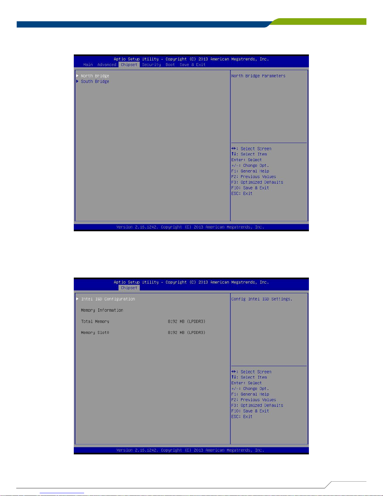
4.4 Chipset
4.4.1 North Bridge
This section provides information on the installed memory size and memory/onboard graphics-
related configuration options.
Page 98
DE-1000
Power Efficient Fanless Computer
| User’s Manual
98
Chapter 4: BIOS Setup
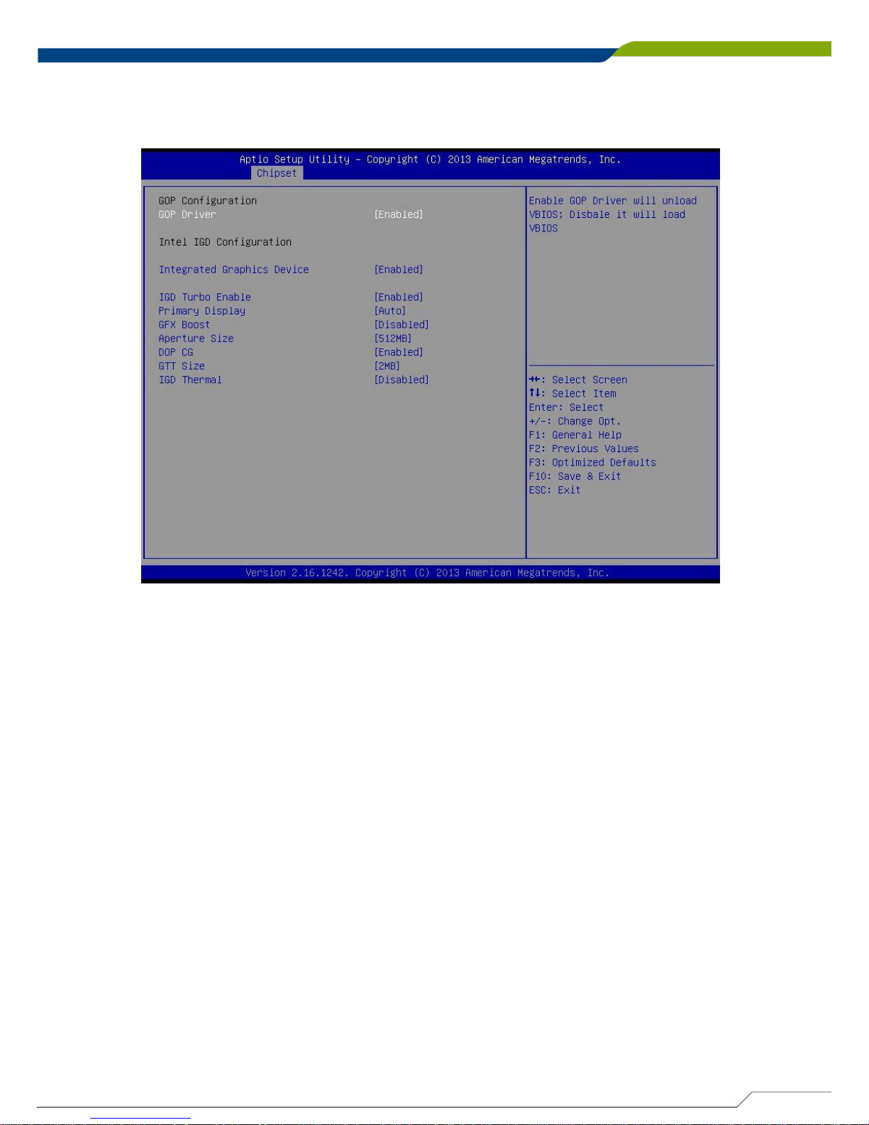
■ Intel IGD Configuration
This section provides onboard graphics-related configuration options.
GOP Driver
This item will allow users to enable or disable GOP Driver.
Integrated Graphics Device
This item will allow users to enable or disable Integrated Graphics Device.
IGD Turbo Enable
This item will allow users to enable or disable IGD Turbo.
Primary Display
"Auto or IGFX or PEG or PCIE or SG” optimal to Primary Display.
GFX Boost
This item will allow users to enable or disable GFX Boost.
Aperture Size
Aperture size optimal between 128MB, 256MB, or 512MB.
DOP CG
This item will allow users to enable or disable DOP CG.
GTT Size
GTT size optimal between 1MB or 2MB.
IGD Thermal
This item will allow users to enable or disable IGD Thermal.
Page 99
DE-1000
Power Efficient Fanless Computer
| User’s Manual
99
Chapter 4: BIOS Setup
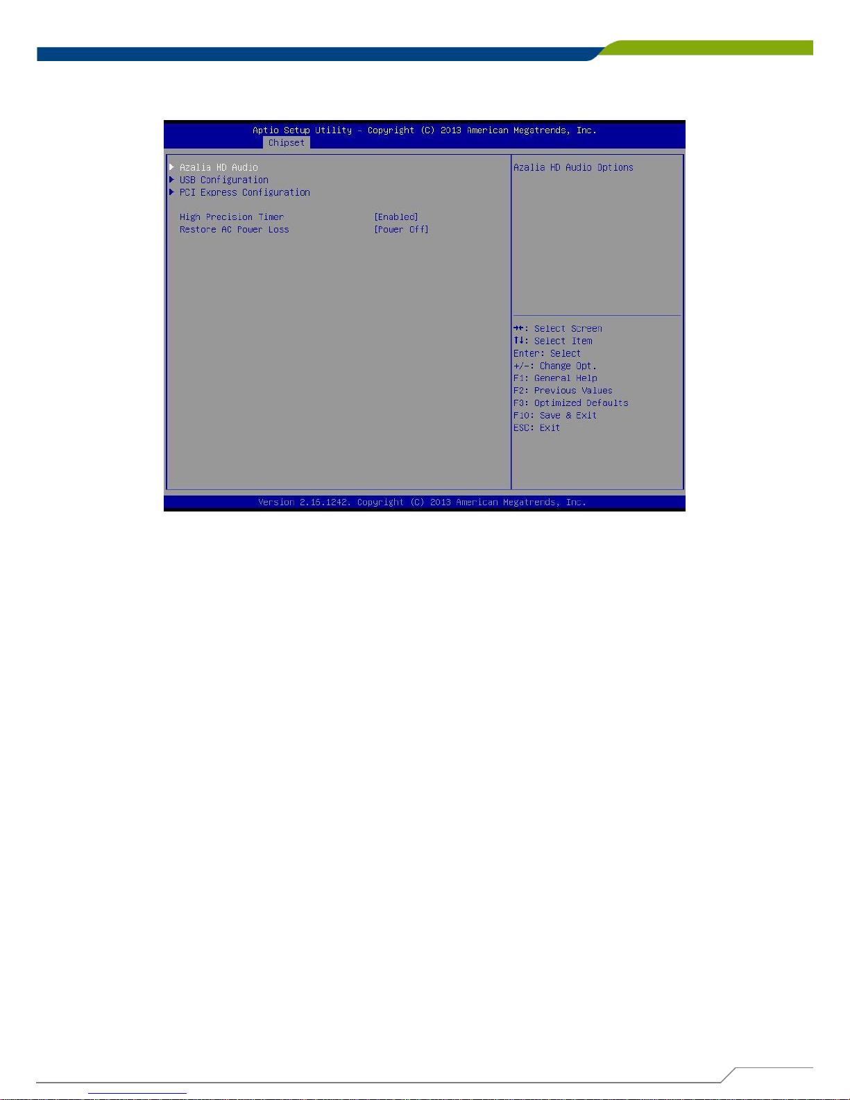
4.4.2 South Bridge
■ Azalia HD Audio
Control detection of the Azaliadevice.
Audio Controller
Enabled: Azalia will be unconditionally enabled.
Disabled: Azalia will be unconditionally disabled.
■ USB Configuration
XHCI Mode
This setting disables/enables the USB XHCI controller. The eXtensible Host Controller
Interface (XHCI) is a computer interface specification that defines a register-level
description of a Host Controller for Universal Serial Bus (USB), which is capable of
interfacing to USB 1.0, 2.0, and 3.0 compatible devices. The specification is also
referred to as the USB 3.0 Host Controller specification.
USB 2 Link Power Management
This setting disables/enables the USB 2 Link Power Management function.
USB 2.0 (EHCI) Support
This setting disables/enables the USB EHCI controller. The Enhanced Host Controller
Interface (EHCI) specification describes the register-level interface for a Host Controller
for the Universal Serial Bus (USB) Revision 2.0.
USB Port 0
This item will allow users to enable or disable USB Port 0.
USB Port 1
This item will allow users to enable or disable USB Port 1.
USB Port 2
This item will allow users to enable or disable USB Port 2.
USB Port 3
This item will allow users to enable or disable USB Port 3.
Page 100
DE-1000
Power Efficient Fanless Computer
| User’s Manual
100
Chapter 4: BIOS Setup
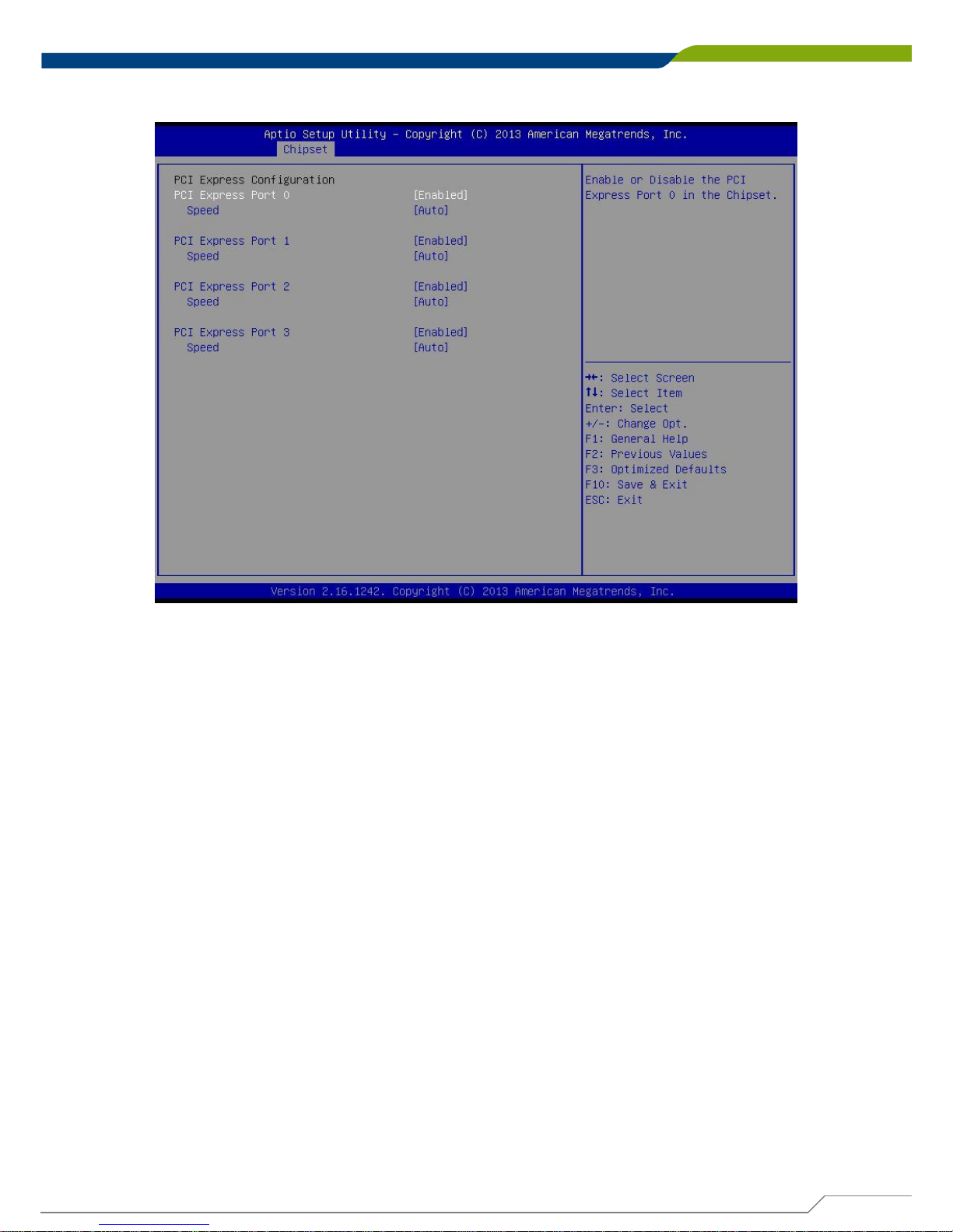
PCI Express Port 0
This item will allow users to enable or disable PCI Express Port 0.
Speed
Change the PCI Express interface speed. Select <AUTO> ,<Gen 2> or <Gen 1>
PCI Express Port 1
This item will allow users to enable or disable PCI Express Port 1.
Speed
Change the PCI Express interface speed. Select <AUTO> ,<Gen 2> or <Gen 1>
PCI Express Port 2
This item will allow users to enable or disable PCI Express Port 2.
Speed
Change the PCI Express interface speed. Select <AUTO> ,<Gen 2> or <Gen 1>
PCI Express Port 3
This item will allow users to enable or disable PCI Express Port 3.
Speed
Change the PCI Express interface speed. Select <AUTO> ,<Gen 2> or <Gen 1>
■ High Precision Timer
Enable or disable High Precision Event Timer (HPET) in the operating system.
■ Restore AC Power Loss
This setting specifies whether your system will reboot after a power failure or interrupt
occurs. Available settings are:
Power Off: Leave the computer in the power off state.
Power On: Leave the computer in the power on state.
Last State: Restore the system to the previous status before power failure or interrupt
occurred.
■ Mini-PCIe/Msata Select (CN4)
This item allows users to select Mini-PCIE or MSATA interface.
■ PCI Express Configuration
 Loading...