

Cincinnati Fan 33S, 75S, 150S, 50S, 200S Installation, Safety, Operation & Maintenance Manual Amd Parts List
...Page 1
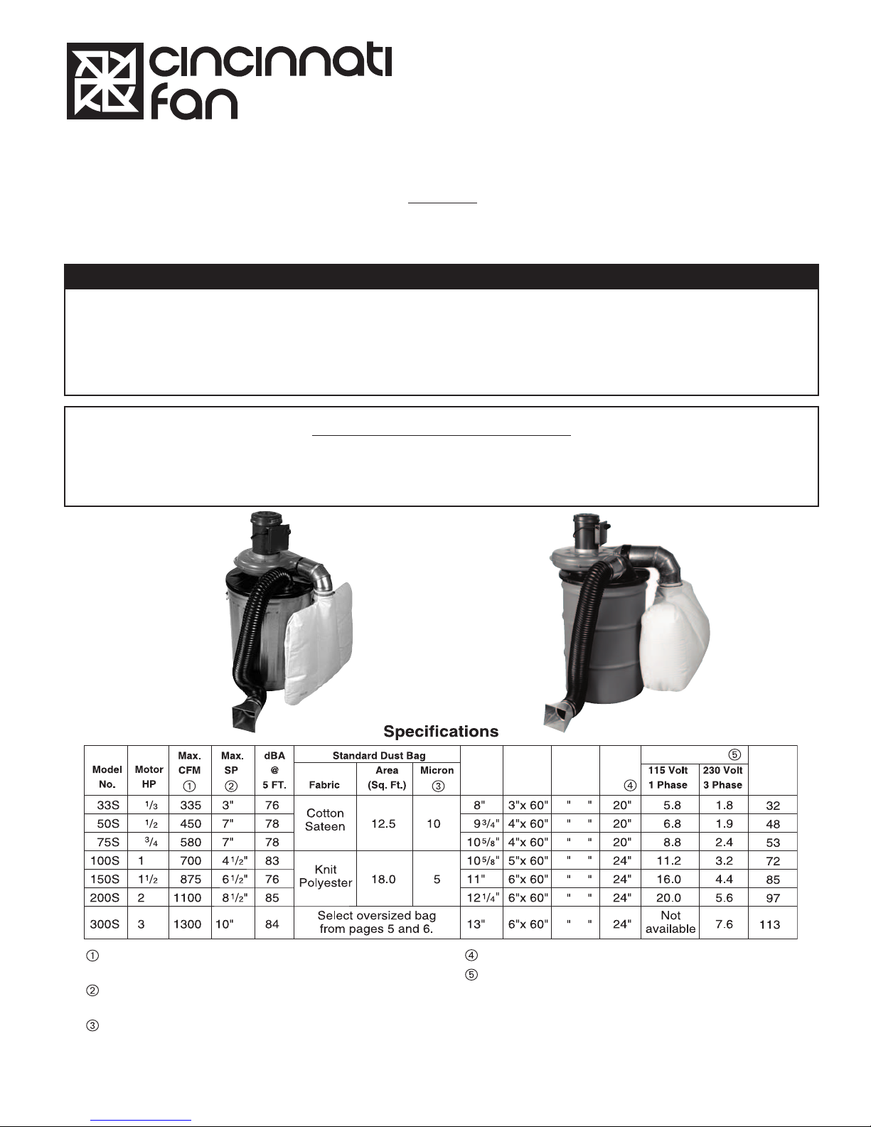
Form: OMM-30-0811
Inlet
Nozzle
Size
Approx.
Ship
Wt.
Inlet
Hose
Size
Blower
Wheel
Dia.
Max.
Drum
Dia.
Full Load Amps
4 x 4
5 x 5
5 x 5
6 x 6
7 x 7
7 x 7
7 x 7
Maximum CFM at 0” S.P. (clean drum, dust bag, with 5
feet of inlet hose and inlet nozzle).
Maximum additional static pressure (SP) at which point
there will be no air flow.
Minimum micron size at which standard dust bag will
capture 99%.
See Section V. INSTALLATION, Section A on page 6.
Starting amps are approximately 6-7 times the full load
amps. High voltage amps are 1/2 of low voltage amps.
Amp loads shown are approximate and will vary with
different motors and/or brands.
All dimensions above are nominal. For complete
dimensions, see page 15.
Supersedes Form: OMM-30-709
Part No.: 01009
Installation, Safety, Operation & Maintenance Manual and Parts List for
Models 33S, 50S, 75S, 100S, 150S, 200S and 300S Portable Dust Collectors
NOTICE:
Read this complete manual before attempting to assemble,
install, operate, move, inspect or service this Dust Collector.
ATTENTION: Receiving Department
All Cincinnati Fan products are packaged to minimize any damage during shipment. The freight carrier is responsible for delivering all items in their original condition as received from Cincinnati Fan. The individual receiving this
equipment is responsible for inspecting this unit for any obvious or concealed damage. If any damage is found, it
should be noted on the bill of lading before the freight is accepted and the receiver must file a claim with the
freight carrier.
LONG TERM STORAGE NOTICE
If this dust collector will NOT be installed and put into service within 30 days, refer to the “Long Term
Storage Instructions” on page 2. Failure to follow all applicable long term storage instructions will void
your warranty.This dust collector must be stored indoors in a clean, dry location.
Models
33S, 50S & 75S
Cans or Drums
are not included
Models
100S, 150S & 200S
1
Page 2

CONTENTS
ITEM ACTION DATE CHECKED
1 Re-inspect unit to insure any protective devices used are functioning properly.
Check for scratches in the finish which will allow corrosion or rust to form.
2 Rotate the blower wheel a minimum of ten (10) full revolutions to keep the
motor bearing grease from separating and drying out.
This step is critical.
Storage - Maintenance Schedule Log
Dangers, Warnings and Cautions .......................................................................Page 3
I. Description ............................................................................................................Page 4
II. Unpacking .............................................................................................................Page 4
III. General Safety Information..................................................................................Page 4
IV. Assembly
A. Models 33S, 50S and 75S................................................................................Page 4
B. Models 100S, 150S 200S and 300S ................................................................Page 4-5
C. Oversized Dust Bags ........................................................................................Page 5
“HB” Type Bags ....................................................................................Page 5-6
“DB” Type Bags ....................................................................................Page 6
V. Installation.............................................................................................................Page 6
A. Proper Cans, Drums and Unit Location............................................................Page 6
B. Exhaust Volumes Required for Different Applications ......................................Page 7
C. Duct Work Recommendations ..........................................................................Page 8
D. Electrical ...........................................................................................................Page 8
VI. Operation...............................................................................................................Page 8
VII. Maintenance ..........................................................................................................Page 9
A. Motor.................................................................................................................Page 9
B. Blower Wheel and Steel Components ..............................................................Page 9
C. Cleaning the Blower Wheel...............................................................................Page 9
D. Replacing the Blower Wheel.............................................................................Page 9-10
E. Replacing the Motor..........................................................................................Page 10
F. Emptying the Can or Drum ...............................................................................Page 10
G. Emptying the Dust Bag .....................................................................................Page 10
H. Cleaning the Dust Bag......................................................................................Page 10-11
VIII. Troubleshooting....................................................................................................Page 11
IX. Exploded View Drawing & Parts List for Models 33S, 50S & 75S....................Page 12
X. Exploded View Drawing & Parts List
For Models 100S, 150S, 200S & 300S ...........................................................Page 13
XI. Exploded View Drawing & Parts List for Oversized Dust Bags .......................Page 14
XII. Dimensions and Performance Curves................................................................Page 15
XIII. Limited Warranty, Liability, Responsibility and Return Policy .........................Page 16
Long Term Storage Instructions
NOTE: Failure to adhere to these instructions voids all warranties in their entirety.
1. Storage Site Selection:
a. Level, well drained, firm surface in clean, dry, location with a temperature range of 50°F (10°C) to 90°F (60°C).
b. Isolated from possibility of physical damage from construction vehicles, erection equipment, etc.
c. Accessible for periodic inspection and maintenance.
2. Carton should be supported under the entire bottom and open at the top allowing it to “breath”
3. If dust collector will be stored for more than three (3) months, the entire unit must be loosely
4. Storage Maintenance:
A periodic inspection and maintenance log, by date and action taken, must be developed and maintained for each unit.
See example below. Each item must be checked monthly.
EXAMPLE:
2
covered with plastic.
Page 3
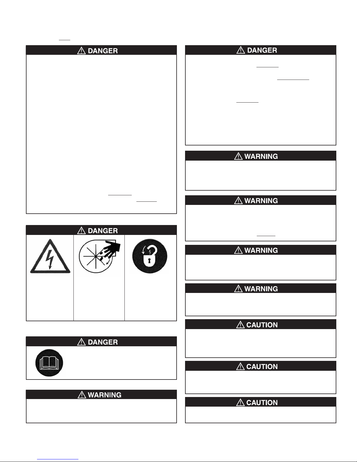
BE SURE TO READ ALL DANGER, WARNING AND CAUTION NOTICES BELOW BEFORE PROCEEDING WITH
ANY INSTALLATION OR OPERATION OF THIS DUST COLLECTOR. MAKE SURE YOU ARE IN COMPLIANCE
WITH ALL
LOCAL, STATE, FEDERAL AND SAFETY GUIDELINES, REGULATIONS AND STANDARDS.
The National Fire Protection Association (NFPA) has
defined the following materials as “reactive metals”:
Aluminum, Magnesium, Tantalum,Titanium and
Zirconium.
Improper handling, machining, collection and disposal of
these materials can result in a severe explosion and/or fire
resulting in death, severe personal injury and extensive,
immediate and surrounding property damage. Consult the
NFPA for current standards. Review of your application
and future type of installation must be completed by
your local Fire Marshal or an Authorized Fire Department
Official prior to the installation of any equipment for this
purpose.
This Standard combines the following previous Standards
into one Standard: NFPA 480, NFPA 481, NFPA 482, NFPA
485 and NFPA 651. NFPA 484 was approved as an
American National Standard on July 19, 2002.
We have reviewed the latest NFPA Standard 484 for
“Combustible Metals, Metal Powders, and Metal Dusts, 2002
Edition” and we have determined:
Cincinnati Fan Dust Collectors ARE NOT
collect any ”reactive metal” material. They DO NOT
designed to
meet
NFPA Standard 484.
According to the National Fire Protection Agency
(NFPA), this dust collector CANNOT
be used to collect
any wood dust or chips AND metal dust or chips. It can
be used for either type of material, but not both.
Hot metal dust or chips from grinders can start a fire or
cause an explosion if mixed with wood dust or chips. Also,
this dust collector CANNOT
be used with sanders or
abrasive planners that have mechanical material feeds.
For clarification, see “NFPA standard 664, NFPA Standard
for the Prevention of Fires and Explosions in Wood
Processing and Woodworking Facilities 2007 Edition” for the
proper design, installation, operation and maintenance of
dust collectors and dust collection systems.
There is a high speed blower wheel inside the blower housing and another one on top of the motor. Both can amputate
fingers or grab loose clothing or neckties. Always wear safety
glasses when operating this dust collector.
Keep dust bag clean.
A clogged dust filter bag may prevent collection of harmful
dust. Read this manual for proper cleaning procedure.
Replace worn or damaged dust bag immediately. NEVER
operate this dust collector without
a dust bag in place.
Hazardous voltage. High speed rotating Lock out / Tag out.
Can cause electrical equipment. To prevent any
shock and death. Can cause severe personal injury
personal injury. Never before performing
operate this equipment any inspection or
without all required service.
safety guards in place.
Read this entire manual.
This manual contains information you
need to insure your safety and satisfactory
operation of your dust collector.
Plastic drums should not be used as they will not support the
weight of the dust collector. DO NOT use any PVC pipe or
hose in any part of the duct system.
This dust collector is not designed to be used out doors
where it will be subjected to the elements. Keep indoors or in
a covered area not subject to rain or snow.
This dust collector is not designed to collect fumes or powders less than 1 micron in size. This dust collector should
NEVER be used to collect ANY liquids.
The motor has a cooling fan and fan cover on top of the
motor. DO NOT place anything on top of the cooling fan
cover at any time. Doing so will cause the motor to overheat
and fail.
This dust collector, when fully assembled, will be top heavy.
It can be overturned if bumped or not placed on a clean, flat,
level surface.
DO NOT use this dust collector to collect ANY type of yard
waste, i.e. leaves, paper, mulch, berries, etc.
3
Page 4

I. DESCRIPTION
This dust collector is designed to help maintain clean, safe
conditions around dust creating machines in workshops and
factories. The flexible hose, included with each unit can be
connected directly onto the dust creating machine.”
See page 7 for exhaust volumes required for different
applications.
This dust collector is not designed to be used in a system that
requires high static pressures. Avoid using any hose or duct
less than 3” in diameter. It will require much higher static
pressure and will restrict air flow.
DO NOT collect any material that could ignite any plastic
or cloth parts of this dust collector.
II. UNPACKING
Carton must be in upright position before opening. Inspect for
any shipping damage and advise freight carrier immediately if
any damage is found. Check Parts List for any missing or
damaged parts.
RETAIN THIS MANUAL FOR FUTURE REFERENCE.
III. GENERAL SAFETY INFORMATION
A. Follow all local, state and federal safety codes including
the National Electrical Code (NEC), the National Fire
Protection Agency (NFPA) standards, the Occupational
Safety and Health Act (OSHA) and the Environmental
Protection Act (EPA).
B. All electrical wiring should be performed only by
qualified personnel or a licensed electrician.
C. Make sure the power source conforms to the
requirements of the dust collector motor.
D. Exercise caution when the unit is in operation. There is a
high speed blower wheel inside the blower housing and
another one on the top of the motor. Both can amputate
fingers or grab loose clothing or neckties. Always wear
safety glasses when operating this dust collector.
All the assembly instructions on the following pages
are based on standard units as catalogued.
With all of the available accessories or options,
we cannot include every combination.
IV. ASSEMBLY
A. MODELS 33S, 50S and 75S (Refer to Figure 1 on
Page 12)
Assembly includes the installation of the air baffle, lid
gasket, discharge elbow, dust bag, hose and nozzle.
1. To install the air baffle and lid gasket, gently place
unit upside down on a cardboard covered flat area.
a. Attach the air baffle (17) as shown using the bolts
included.
b. Remove the paper protection from the sticky side
of the lid gasket (18). Install the gasket on the
underside of the drum lid/inlet guard assembly (11)
so that the side of the gasket is against the lip of
the lid.
2. Carefully turn over the assembly so the motor is on
top and place it on top of a 30-35 gallon can or drum.
NOTE:
If you are installing the standard dust bag,
and 75S) continue with Step 3 below.
If you are installing an oversized dust bag,
Models 50S & 75S only) go to Section C on page 5.
3. a. The discharge elbow (8) has two 1/8” holes at one
end of the elbow. Slide the end with the two holes
over the discharge guard (5) on the blower housing.
Line up the two holes in the elbow with the two
holes in the guard. Install and tighten the 2 self
tapping screws included in the plastic bag of
hardware.
b. Slide the dust bag clamp (9) over the inlet collar of
the dust bag (10). Slide the dust bag collar over the
end of the discharge elbow (8). The dust bag inlet
collar should overlap the end of the bag elbow by
about 2”. The clamp should be centered in between
the two ends. Tighten the clamp with a screw driver
or nut driver.
c. Model 33S ONLY. (For models 50S & 75S, go to
Step e)
Mount 4” to 3” sheet metal inlet reducer (15) onto
inlet collar of drum lid (11). Tighten draw lug nut &
screw.
d. Slide hose clamp (13) over one end of hose (14)
and slide hose over inlet reducer (15). Tighten
clamp.
e. Model 50S & 75S:
Slide hose clamp (13) over one end of hose (14)
and slide hose over inlet collar of lid (11). Tighten
clamp.
f. Models 33S, 50S and 75S.
Slide hose clamp (13) over opposite end of hose
(14) and slide hose onto inlet nozzle (12). Tighten
clamp.
(Models 33S, 50S
(Available on
B. MODELS 100S, 150S, 200S and 300S (Refer to
Figure 2 on Page 13)
Assembly includes the installation of the inlet deflector,
intake cylinder, lid gasket, discharge bag elbow, dust bag,
hose and nozzle.
1. To install the intake cylinder, deflector elbow and lid
gasket, gently place the unit upside down on a
cardboard covered flat area. Two people should
perform this function.
a. To attach the inlet deflector (16B), remove the two
1/4-20 nuts and washers that hold the inlet elbow
(16A) onto the drum lid (11). Install the inlet
deflector (16B) over the same bolts that hold the
inlet elbow (16A). Reinstall the 1/4-20 nuts and
washers and tighten.
4
Page 5

IV. ASSEMBLY (Continued)
NOTE
The intake cylinder/guard (#19) in Step 1b below, MUST
be installed. Failure to install this part will GREATLY
reduce the airflow (CFM) of the dust collector.
b. Attach the intake cylinder (19) with the four 1/4-20
bolts and lock washers that were supplied in the
hardware packet. The four bolts go through the four
mounting lugs on the intake cylinder and are
screwed into the 4 threaded inserts in the drum lid
(11).
c. Remove the paper protection from the sticky side of
the lid gasket (18). Install the gasket on the
underside of the drum lid (11) so that the side of
the gasket is against the lip of the lid.
2. Two people should turn over the assembly so the
motor is on top and place it on top of a 55-gallon can
or drum.
3. Attach inlet hose and nozzle.
Step 3 is for Model 100S ONLY. For Models 150S,
200S and 300S, go on to Step 4 below.
a. Mount the 6” to 5” metal reducer (15) onto the inlet
elbow (16A). Tighten the draw lug nut on the
reducer.
b. Slide hose clamp (13) over one end of hose (14)
and slide hose over inlet reducer (15). Tighten
clamp.
4. Slide hose clamp (13) over opposite end of hose (14)
and slide hose over inlet nozzle (12). Tighten clamp.
NOTE:
If you are installing the standard dust bag, (Models 100S,
150S and 200S) continue with Step 6 below.
If you are installing an oversized dust bag
Models 100S, 150S and 200S) go to Step C below.
All Model 300S units require an oversized dust bag
Step C below.
6. a. The discharge elbow (8) has two 1/8” holes at one
end of the elbow. Slide the end with the two holes
over the discharge guard (5). Line up the two holes
in the elbow with the two holes in the guard. Install,
and tighten, the 2 self tapping screws included in
the plastic bag of hardware.
b. Slide the dust bag clamp (9) over the inlet collar of
the dust bag (10). Slide the dust bag collar over
the end of the bag elbow (8). The dust bag inlet
collar should overlap the end of the bag elbow by
about 2. The clamp should be centered in between
the two ends and above the rib of the bag elbow.
Tighten the clamp.
C. INSTALLING OVERSIZED DUST BAGS (Refer to
Figures 3 or 4 on page 14).
Steps 1a through 1d are for all Models 50S, 75S, 100S,
150S, 200S and 300S.
1. a. The discharge bag elbow (8) is not used. The
discharge bag elbow is never used on Model 300S.
, (Available on
. Go to
b. Slide a hose clamp (4 or 9) onto both ends of the
dust bag connector hose (6 or 10).
c. Slide one end of the hose over the guard (5) on
the blower housing discharge. Tighten the hose
clamp.
d. Slide the hose connector (5 or 8) into the other
end of the hose so that half of the connector
length is inside the hose. Tighten the hose clamp
around the hose and connector.
For “HB” Hanging Bags (Figure 3), proceed with Step
2. DO NOT use “HB” Bags on Models 50S & 75S.
For “DB” Drum Bags (Figure 4) proceed to Step 5 on
Page 6.
2. “HB” type Hanging Bags are only recommended
when there is not enough floor space for a second
55 gallon drum next to the dust collector. However,
they are more cumbersome to empty and require
emptying much more often. A “DB” type bag will be
much easier to empty and will not require being
emptied as often.
a. Assembly of the “J” hooks (2) onto the angle iron
ring (1).
Thread a 1/4-20 nut all the way onto a “J” hook.
Install a 1/4” flat washer. Put threaded end of the
“J” hook nut and washer assembly through a hole
in the angle iron ring. Install a second washer on
top of the ring hole. Install a second 1/4-20 nut
on top of the flat washer and tighten. Repeat
these steps for each “J” hook.
3. a. Slide a hose clamp (4) over the inlet collar in the
side of the HB dust bag (3).
b. Slide the inlet collar of the dust bag over the
exposed end of the hose/bag connector (5) that
you connected in Step C-1,d above.
c. Secure the dust bag collar to the hose connector
with the hose clamp.
4. This step will be performed much more safely
with two people on separate ladders.
a. Put one bag grommet over each “J” hook in the
ring/hook assembly.
b. Carefully start climbing the ladders while holding
onto the ring/bag/hose assembly.
c. Raise the ring/bag/hose assembly high enough
above the ground without putting to much tension
on the bag or the hose entering the side of the
bag. Also make sure the hose (6) is not “kinked”
at the discharge of the dust collector. This is the
proper height for the ring to hang off of the
ground.
d. Measure the distance from the ring to the ceiling
joist, rafter or truss.
e. Securely
or truss with approved cable or chains.
f. The bag should be hanging so it doesn’t
touch the floor AND it doesn’t pull on the
dust collector discharge hose. See Figure 3
on page 14.
hang the ring from a ceiling joist, rafter
5
Page 6

IV. ASSEMBLY (Continued)
N
OTE:
Never let an HB type hanging bag collect over 12” of dust or
chips in the bottom of the bag. When dust or chips reach a
depth of 12”, the bag must be emptied. If not, the weight of the
material inside the bag may cause the bag to tear from the
grommet straps at the top or at the zipper in the bottom.
See Dust Bag Cleaning Instructions on page 11.
For “DB” Drum Bags (Figure 4) proceed with Step 5.
5. The “DB” type Drum Mount dust bags come in
three sizes. Approximate dimensions are:
DB24x40 is 24” diameter x 36” high for models 50S
and 75S. Available in two fabric types.
DB24x80 is 24” diameter x 72” high for models
100S, 150S, 200S and 300S. Available in three
fabric types.
DB48x80 is 48” diameter x 72” high for models
100S, 150S, 200S and 300S. Available in three
fabric types.
a. You should have completed Steps C-1,a through
C-1,d on page 5.
b. Slide a hose clamp (9) over the inlet collar in the
side of the dust bag.
c. Slide the inlet collar of the dust bag (7) over the
exposed end of the hose connector (8) that you
installed in Step C-1,d on page 5. Secure the
dust bag collar to the hose connector by
tightening the hose clamp.
d. The “DB” type Drum Mount dust bag has an
outer and an inner sleeve in the bottom opening
of the bag. There is also a belt on the outside of
the bag. Loosen the belt as far as possible.
e. Roll back the outer sleeve and slide the inner
sleeve inside an open top 55 gallon drum. Now,
unroll the outer sleeve down over the outside of
the drum so that the bottom of the bag overlaps
the top of the drum by 4-6”. Tighten the belt as
tight as possible
NOTE:
If you will be collecting dust smaller than 10
microns, we recommend you remove the belt
from the bag and install a 55 gallon drum lid
clamp around the top of the drum. This will
provide a better seal between the drum and the
dust bag.
f. There is a single grommet in the top, center of
the bag. Connect one end of a rope or cable
through the eye of the grommet and connect the
other end to a rafter or truss in the ceiling. This is
only needed to hold the bag up when the dust
collector is turned off. Leave about 12” of slack
in the rope or cable.
V. INSTALLATION
A. Proper Cans, Drums and Unit Location
Models 33S, 50S and 75S should be mounted on top of a
25-30 gallon garbage can or a 30-35 gallon drum. The
garbage can or drum should have a diameter no less than
18” and not more than 20”. Do not use plastic cans or
drums. A fiber can or drum may be used if it has a fire
resistant foil liner and it can support the weight of the dust
collector.
Models 100S, 150S, 200S and 300S should be mounted
on top of a 55 gallon, roll-top, steel drum only. The drum
should have a diameter no less than 22” and not more than
24”. Do not use plastic or fiber drums. Place the
assembled dust collector as near as possible to the dust
generating source.
6
Page 7

(2) CFM's required are minimums per each equipment type. Duct
velocity should not be less than 3500 FPM to prevent wood dust
from settling in duct work.
(3) Requires 2 nozzles or hoods. CFM’s shown are total CFM for
both nozzles or hoods.
(4) For all metalworking applications, duct velocity should be at least
3500 FPM for light grinding or buffing and at least 4500 FPM for
heavy grinding or buffing to prevent settling in duct work.
(5) The wheel hood should cover at least 75% of the wheel to be
considered a good enclosure.
WOODWORKING
METALWORKING
Equipment Size
Min. CFM
Required
(2) Equipment Size
Min. CFM
Required
(4)
Jointer Knife Length = Up to 6" 350
6+" to 12" 440
12+" to 20" 550
over 20" 800
Sander, Belt Belt Width = Up to 6" 790 (3)
(Horizontal) 6+" to 9" 900 (3)
9+" to 14" 1240 (3)
Sander, Disc Disc Diameter = Up to 12" 350
12+" to 18" 450
18+" to 26" 550
Sander, Drum Drum Surface = Up to 200 350
(in square inches) 201 to 400 550
401 to 700 785
701 to 1400 1100
Saw, Band Blade Width = Up to 2" 700 (3)
2+" to 3" 900 (3)
3+" to 4" 1350 (3)
Saw, Radial Hood behind blade = 430
From port on blade guard = 70
Total = 500
Saw, Swing Blade Diameter = Up to 20" 350
over 20" 440
Saw,Table Blade Diameter = Up to 16" 350
16+" to 24" 440
over 24" 550
Variety with dado = 550
Planer, Single Knife Length = Up to 20" 785
20+" to 26" 1100
Buffing, Belt Belt Width = Up to 3" 220
3+" to 5" 300
5+" to 7" 390
7+" to 9" 500
9+" to 11" 610
11+" to 13" 740
Buffing, Wheel Wheel Width = 2" 300
(5) 3" 500
4" 610
5" 740
6" 1040
Grinding Wheel Wheel Width = 1" 220
Wheel speeds (5) 1-1/2" 220
below 6500 sf/m 2" 390
3" 500
4" 610
5" 880
6" 1200
Grinding Wheel Wheel Width = 1" 220
Wheel speeds (5) 1-1/2" 390
above 6500 sf/m 2" 610
3" 740
4" 880
5" 1200
(1) The exhaust volume (CFM) requirements shown are “American
Conference of Governmental Industrial Hygienists (ACGIH
®
),
Industrial Ventilation: A Manual of Recommended Practices,
19th Edition. Copyright 1986. Reprinted with permission.”
Consult manual for more detailed recommendations. Contact
them at www.acgih.org.
How To Select The Proper Size Dust-Master Dust Collector
Although Cincinnati Fan Dust-Master dust collectors will give you
excellent results in collecting wood chips, fine dust and metal shavings,
they are not designed to work in large central system applications. These
are portable units that can be moved from machine to machine. To select
the proper size Dust-Master, use the criteria below:
1. Add the “CFM REQUIRED” for each machine per the above chart. This
is your TOTAL CFM REQUIRED.
2. Now, select the Dust-Master model from page 1 with a “Max. CFM”
greater than your TOTAL CFM REQUIRED in Step 1. If none of the
models on page 1 have a Max. CFM greater than your TOTAL CFM
required, you will need more than one unit.
3. If the unit will be in a “fixed installation” all ductwork should be sheet
metal duct instead of flexible hose.The pressure drop through flexible
hose can be 2-3 times that of smooth wall pipe. DO NOT use any PVC
or plastic pipe. It can deliver a severe static electric shock caused
by high velocity dust passing through it.
4. The Dust-Master should be located as close to the machine as possible
and preferably no more than 10 feet away.
5. Use as few elbows as possible in your ductwork. The loss through one,
90° elbow is equal to approximately 10 feet of straight, smooth wall pipe.
6. If the dust collector will be used for more than one machine, install slide
gate dampers in the duct at each machine to “close off” that section of
duct when using another machine. This will allow the dust collector to pull
from only one machine at a time and thus increase the dust collector
performance.
7. Typically, a Model 150S will work with up to 20 total feet of duct, a model
200S will work with up to 30 total feet of duct work and a 300S will work
with up to 75 total feet of duct. These values are based on having
dampers at each machine connection (as in note 6 above) and all duct
work is smooth wall, sheet metal.
Abbreviations used in charts:
CFM = Cubic feet of air per minute
FPM = Feet per minute
sf/m = Surface feet per minute
Also see Section C on Page 8.
B. Exhaust Volumes Required for Different Applications (1)
7
Page 8

C. Duct Work Recommendations
The maximum CFM rating for each model dust collector
should be greater than the minimum required CFM as
listed in the Exhaust Volumes Required for Different
Applications chart on page 7.
If you will be connecting the dust collector into a piping
system for more than one machine, the dust collectors
maximum CFM should be greater than the minimum CFM
required for each machine in the system. If the piping
system will have slide gate dampers at each machine, with
only one machine operating at a time, then the dust
collector can handle more machines as long as the CFM
required does not exceed the maximum CFM of the dust
collector. As a rule of thumb, one dust collector can handle
multiple machines as follows:
Model 33S & 50S..One machine only.
Model 75S ...........Two machines if within 5 feet of each other.
Model 100S .........Two machines if within 10 feet of each other.
Model 150S .........Two machines if within 20 feet of each other.
Model 200S .........Up to 30 feet of 5” duct, and 3 machines.
Model 300S .........Up to 75 feet of 5” duct, and 3-4 machines.
NOTE:
The number of machines you can collect from will depend on
the CFM required per machine.
General Recommendations for Ductwork Systems:
1. The National Fire Protection Agency (NFPA) will no
longer permit a single dust collector to be used to
collect BOTH wood dust or chips AND metal dust or
chips because of the possibility of a fire and/or
explosion.
2. DO NOT use any PVC pipe or flexible hose for
duct work. This is no longer permitted by the
National Fire Protection Agency (NFPA). Dust
traveling through PVC pipe or hose can build up a
static electric charge.
3. Limit the use of flexible hose in any duct work to as
little as possible. The pressure drop (resistance)
through flex hose can be 2-3 times greater than
smooth wall sheet metal pipe.
4. If connecting a dust collector to more than one
machine, you should install slide gate dampers at
each machine so the dust collector is only pulling
from one machine at a time.
5. Keep the number of duct elbows to a minimum. A
90° elbow has the same pressure drop (resistance)
as 10 feet of straight pipe.
6. Estimate 2 CFM reduction in air flow for each foot of
straight pipe and 20 CFM reduction for each 90°
elbow.
7. Pneumatic conveying of wood dust requires a
minimum air velocity of 3500 feet per minute (FPM)
in the duct or hose. For metal dust, the velocity can
be from 3500 FPM to 4500 FPM. Velocities less than
these will allow the dust to settle in the duct work or
hose. Therefore, the CFM must not be reduced
below these velocities.
8. Connect the dust collector inlet hose to the
connector port built into the dust producing machine.
If there is no port on the machine, place the inlet
hose and inlet nozzle as close as safely
where it will collect the most dust.
9. DO NOT use any duct or hose smaller than 3”.
possible
D. Electrical
All electrical connections and wiring must be
performed by qualified personnel or a licensed
electrician. Models 33S, 50S, 75S and 100S, with single
phase, TEFC motors are pre-wired at the factory with a
cord, plug and switch to operate on a 115 Volt, 1 Phase, 60
Hertz power supply. These motors are also connected for
the proper blower wheel rotation.
All other motors must be wired by the user for the
operating voltage as stated on the motor nameplate and
wiring diagram. All wiring must be in accordance with
Underwriters Laboratories (UL) and the National
Electric Code (NEC). After all wiring is properly
completed, apply power to the motor for 1-2 seconds and
then turn it off. As the motor slows down, observe the
rotation of the motor cooling fan on top of the motor. The
proper rotation for all dust collector motors is Clockwise
(CW) when looking down on top of the motor. If the motor
is turning Counter-Clockwise (CCW), lock out the power to
the motor and then make the wiring changes per the motor
wiring diagram either on the motor nameplate or inside the
motor conduit box.
VI. OPERATION
The only operation steps that need to be monitored are
emptying the can or drum and the dust bag. The can or
drum should never be allowed to become over 1/3 full. The
bag should never be more than 1/4 full.
8
Page 9

VII. MAINTENANCE
HIGH SPEED ROTATING EQUIPMENT CAN CAUSE
SEVERE PERSONAL INJURY.
There is a high speed blower wheel inside the blower
housing and another one inside the fan cover on top of the
motor. Always disconnect or lock out power to the motor
and let the wheel come to a complete stop BEFORE
attempting any inspection, service, maintenance or moving
of this dust collector.
A. Motor
The bearings in the motor are lubricated and sealed for life so
they will not require any additional lubrication during the life of
the motor. Keep the motor clean as excessive dirt may prevent
proper cooling of the motor. Use no more than 40 PSI air to
blow off excessive dirt.
B. Blower Wheel and Steel Components
The cast aluminum wheel and steel components are generally
maintenance free during the life of the unit. It is possible that
very fine, sticky dust particles can build up on the blades and
back plate of the blower wheel. When the unit is lifted off of the
can or drum for emptying of the can or drum, you should also
inspect the blower wheel for any material buildup. Using a
flashlight, look into the blower inlet underneath the lid. Any
material that has built up on the wheel must be removed to
prevent the wheel from an imbalance situation that could
cause a premature motor bearing failure and/or dangerous
wheel failure. For proper cleaning instructions, see the
following section.
C. Cleaning the Blower Wheel
This operation is best performed with the dust
collector sitting on top of the can or drum.
1. Lock out and disconnect power to the motor.
2. Disconnect the discharge bag elbow (8) from the
blower housing discharge. On units with oversized
dust bags, disconnect the flex hose from the blower
discharge.
3. There are two pop rivets that connect the discharge
guard (5) to the top section of the blower housing
discharge (4). These pop rivets should be drilled out
with a 3/16” drill bit.
4. Using a 7/16“ socket and wrench, loosen and
remove all the 1/4-20 nuts & bolts holding the two
housing halves (4 and 7) together around the blower
housing flange.
5. After removing all the nuts and bolts, use a screw
driver or pry bar to carefully break the sealant in
between the two housing halves.
6. After the sealant is loosened, lift the motor side
housing (4) and motor assembly off of the inlet side
housing (7).
7. Set the blower housing/wheel/motor assembly on a
work bench resting on the side of the motor.
8. If possible, clean the blower wheel (6) with a wire
brush while the wheel is still on the motor shaft. Use
HAZARDOUS VOLTAGE CAN CAUSE ELECTRICAL
SHOCK AND DEATH.
Always disconnect or lock out power to the motor and let
the wheel come to a complete stop BEFORE attempting
any inspection, service, maintenance or
moving of this dust collector.
WEAR EYE PROTECTION.
Always wear eye protection when operating, servicing or
cleaning this dust collector with a high pressure air hose.
an air hose to blow off the wheel when finished. If it
is not possible to clean the wheel while on the motor
shaft, see Section D. Replacing The Blower
Wheel below.
9. If cleaning the blower wheel while on the motor shaft
was successful, use a putty knife to clean the
excess sealant caulk off of the flanges of both
blower housing halves (4 and 7).
10. Apply a fresh bead of silicone sealant to the housing
flange on the blower housing inlet side (7).
11. Carefully reset the blower housing motor side (4) on
top of the blower housing inlet side (7) so that the
outside of the flanges and the discharges line up.
12. Reverse Steps 5 through 1, at left, to complete
reassembly.
D. Replacing the Blower Wheel
This operation is best performed with the dust
collector sitting on top of the can or drum.
1. First complete Steps 1 through 7 for Step C.
Cleaning the Blower Wheel, at left.
2. Now, follow the following steps to replace the blower
wheel.
3. Measure the distance from the front of the wheel
hub to the end of the motor shaft. Keep this
dimension.
4. There are two set screws in the blower wheel. Using
a 5/32” Allen wrench, remove the two set screws
from the wheel hub.
5. Using two pry bars, place the pry bars behind the
back plate of the wheel so that the pry bars are
located behind two opposite wheel blades. This will
give you the most leverage. Pry the wheel off of the
motor shaft being careful not to damage or distort
the blower housing.
6. After removing the wheel, clean it thoroughly with a
wire brush if you will be reusing it.
7. If the wheel is eroded, DO NOT reuse it. It will be
out of balance and will damage the motor bearings.
8. If you can reuse the wheel, you MUST replace the
set screws in the wheel hub. Set screws can never
9
Page 10

be used more than once. Replace them with 5/1618 set screws with a knurled head and a nylon
locking patch on the side of the screw.
9. File any burrs on the motor shaft from the previous
set screws and dress up the keyway in the motor
shaft with a file.
10. Using a rubber or raw hide hammer, reinstall the
present wheel or install a new wheel onto the motor
shaft. Locate the wheel hub on the motor shaft to the
same dimension you took in Step 3 on page 9.
DO NOT use a steel hammer. It can damage the
wheel and/or the motor bearings.
11. Line up the keyway in the motor shaft with the keyway
in the wheel hub.
12. Install a new 3/16” square shaft key into the keyway.
The key should be no longer than 1-1/2”. The key
should be positioned so it is flush with the end of the
wheel hub.
13. Spin the wheel by hand to make sure it is not rubbing
against the motor side of the blower housing.
14. Tighten the set screw over the shaft key first. Then
tighten the set screw onto the motor shaft. Both
screws should be tightened to 165 inch pounds.
15. Use a putty knife to clean the excess sealant caulk off
of the flanges on both blower housing halves.
16. Apply a fresh bead of silicone sealant to the housing
flange on the blower housing inlet side (7).
17. Carefully reset the blower housing motor side (4) on
top of the blower housing inlet side (7) so that the
outside of the flanges and the discharges line up.
18. Look into the discharge to make sure the blower
wheel is not touching the inlet side of the blower
housing.
19. Reverse Steps 5 through 1, on page 9 to complete
reassembly.
E. Replacing the Motor
Before you attempt to replace the motor, make sure you have
the correct replacement motor in your possession. All dust
collector motors have the following characteristics:
a. All Models 33S through 200S have a 56C frame
with a C-Face mounting and a 5/8” shaft.
b. Model 300S has a 145TC frame with a C-Face
mounting and a 7/8” shaft.
c. All motors used in the U.S.A. and Canada are
3450 RPM.
d. All motors are Totally Enclosed (TEFC) or
Explosion Proof (EXP). NEVER replace an EXP
motor with a TEFC motor.
e. The motor horsepower (HP) should match the HP
of the motor you are replacing
f. Make sure the new motor matches the operating
voltage, phase and hertz of the old motor.
To replace the motor, follow Steps 1 through 8.
This operation is best performed with the dust collector
sitting on top of the can or drum.
1. First complete Steps 1 through 7 for Cleaning the
Blower Wheel, on page 9.
2. Now, complete Steps 3 through 8 for Replacing the
Blower Wheel, on page 9-10.
3. Before removing the motor, notice the location of the
motor conduit box with relation to the blower
housing.
4. With a 9/16” socket wrench, remove the four 3/816UNC bolts that hold the motor onto the motor side
blower housing (4).
5. Remove the old motor.
6. Install the new motor onto the blower housing with
the conduit box in the same orientation as noticed in
Step 3 above.
7. Replace or reinstall the four motor bolts and lock
washers through the blower housing and into the
four holes in the motor C-Face. Thread all bolts by
hand and then tighten them with the socket wrench.
8. Follow Steps 10 through 19 for Replacing the
Blower Wheel, at left, to complete the reassembly
of the dust collector.
F. Emptying the Can or Drum
NEVER ATTEMPT TO EMPTY A CAN OR
DRUM WHILE THE UNIT IS OPERATING.
Empty the dust collector can or drum when it becomes 1/3
full. If the can or drum becomes too full, it will reduce the
suction of the dust collector.
G. Emptying the Dust Bag
NEVER ATTEMPT TO EMPTY A DUST
BAG WHILE THE UNIT IS OPERATING.
If you are collecting heavier chips, they will settle in the
can or drum. Finer, lighter dust will go on into the dust bag.
Therefore, the dust bag must also be emptied. The
National Fire Protection Association (NFPA) states in their
Standard 664, that wood dust
emptied “every day or less if warranted.” They should
then be checked for holes, rips or loose seams that could
leak. Emptying of the dust bag should only be performed
by trained personnel wearing the proper clothing and the
proper respiration equipment. How often you should empty
the dust bag is really a judgment call. It will vary with the
weight of the material you are collecting. No matter what
you are collecting, NEVER let the bag get more than 1/4
full. The major cause of having to replace dust bags is
due to ripping because of too much weight in the
bottom of the bag.
in dust bags MUST be
H. Cleaning the Dust Bag
NEVER ATTEMPT TO OPERATE A DUST COLLECTOR
WITHOUT THE DUST BAG IN PLACE.
WARNING:
If dust collector has been used to collect ANY materials
included in the following list, it should NOT be cleaned. The
dust bag must be disposed of using approved methods and
procedures as adopted by the proper regulatory agency or
agencies.
A. Any carcinogenic or biological materials.
B. Any flammable materials.
C. Any explosive materials.
D. Any water reactive materials.
E. Any nuclear materials.
10
Page 11

F. Any materials with cleaning instructions that are in
SYMPTOM POSSIBLE CAUSE(S) CORRECTIVE ACTION
contradiction with the following cleaning instructions.
G. Any materials considered to be unsafe if they come
in contact with the body.
Cleaning Instructions
Acrylic Coated Polyester Felt, Teflon® Coated Polyester
Felt or Nomex® Felt Dust Bags:
Because of the special coatings that have been applied to
these materials, we do not recommend that these bag types be
cleaned. They should be replaced when necessary or at least
annually.
Cotton Sateen & Knit Polyester Dust Bags:
4. Shake bag well to dislodge any material sticking to
the pores of the bag.
5. Lay bag flat on table or floor.
6. Vacuum bag on both sides.
7. Put bag in washer.
8. Set washer for Gentle cycle.
9. Set water temperatures to COLD for wash and rinse
cycles.
10. Add 1/4 cup of Woolite® detergent.
11. After washing is completed, hang bag on line to dry.
DO NOT put in dryer.
12. After bag has dried, turn it right side in.
13. Do not use dust bag until it has thoroughly dried.
1. Inspect dust bag for holes. If any holes are found the
bag must be replaced.
2. Unzip any zipper in the bag.
3. Turn bag inside out.
NOTICE: Overwashing, harsh detergents and/or drying too
fast will cause bag to shrink and the inlet collar might
become too small to fit back onto the unit. Shrinkage is a
non-warranty claim. Dust bags can typically only be
washed one time.
VIII. Troubleshooting Chart
Unit will not operate.
Motor overheating.
Excessive noise.
1. Improper electrical connection.
2. Defective fuse or circuit breaker.
3. Loose wiring connections.
4. Power turned off elsewhere.
5. Defective motor.
1. Voltage supplied to motor too high
or too low.
2. Improper electrical connection.
3. Dust bag and/or hose not in place.
1. Wheel rubbing inside of housing.
2. Worn or eroded blower wheel.
3. Accumulation of material on wheel.
4. Worn motor bearings.
1. Turn OFF and lock out power to the motor. Check
wiring to make sure it conforms to wiring diagram for
the motor for the operating voltage.
2. Check and replace any defective or blown fuse or
circuit breaker. DO NOT oversize for the circuit.
3. Check for loose wiring connections.
4. Check for other power control locations.
5.`Have motor checked at authorized motor repair shop.
NOTE: A normal
1. Turn OFF and lock out power to the motor. Check
actual incoming voltage to motor.
2. Turn OFF and lock out power to the motor. Check
wiring to make sure it conforms to wiring diagram for
the motor for the operating voltage.
3. Must have dust bag and 5 foot hose minimum.
1. Turn OFF and lock out power to the motor. Check
wheel location inside housing. If rubbing, see Section
VII-D on pages 9 and 10.
2. Turn OFF and lock out power to the motor. Check
wheel. Clean or replace if necessary.
3. Turn OFF and lock out power to the motor. Check
wheel. Clean or replace if necessary.
4. Replace motor. See Section VII-E on page 10.
motor will operate at 174° F.
Low suction.
1. Incorrect blower rotation.
2. Suction hose too long.
3. Dust bag dirty
1. MOST COMMON CAUSE
Turn unit OFF and observe the rotation of the motor
cooling fan on top of the motor. It must be turning
Clockwise (CW). If it is turning Counter Clockwise
(CCW), reconnect the motor wiring leads for CW
rotation. See motor wiring diagram.
2. Place unit closer to dust source and shorten hose.
3. DO NOT remove dust bag while unit is operating.
Turn OFF power to the motor. Remove dust bag and
clean or replace it per the instruction in Section H on
pages 10 and 11.
11
Page 12
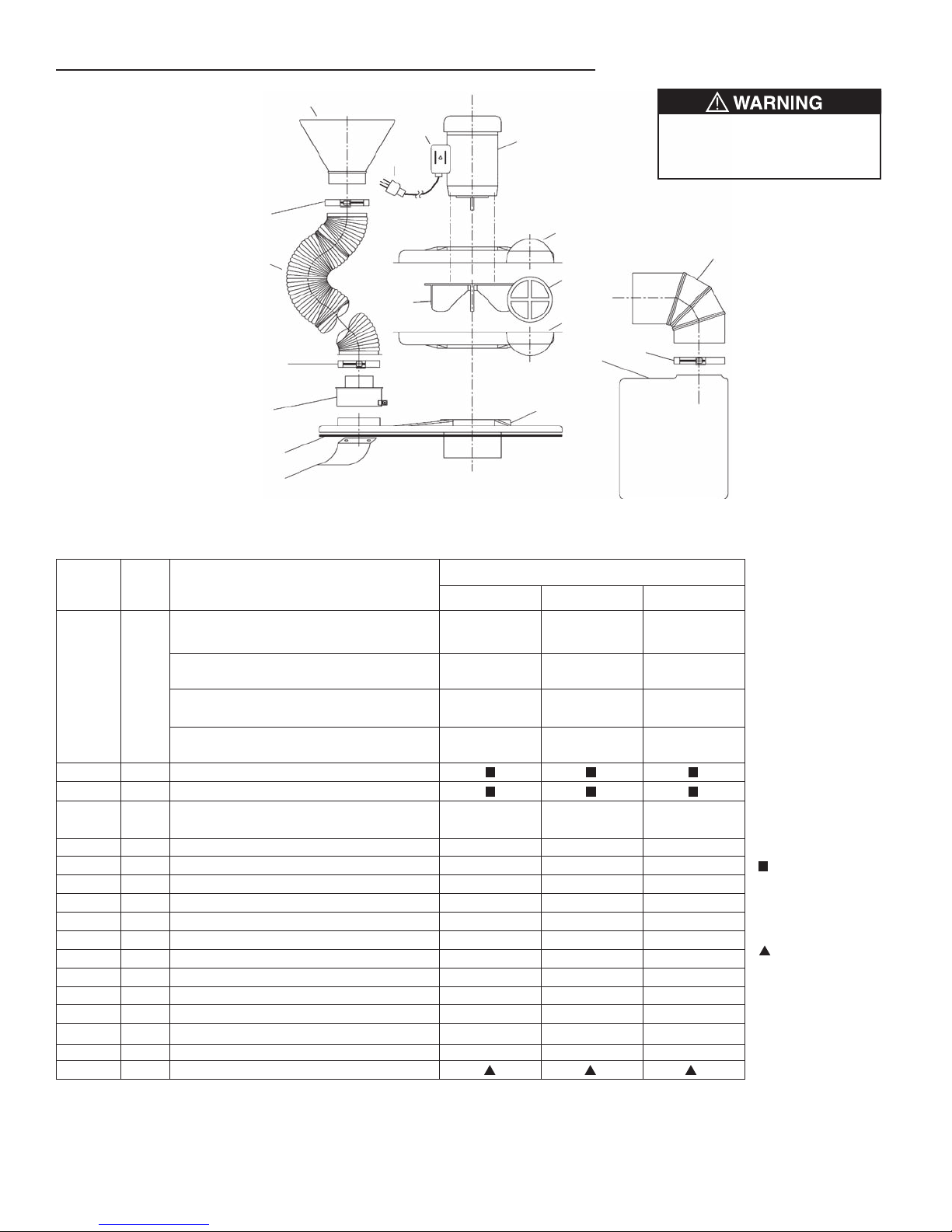
11
9
6
5
8
3
18
17
15
2
1
4
14
7
12
10
13
13
Ref.
No.
Qty./
unit
Description
Part Number for Model
Standard Replacement Parts List for Models 33S, 50S and 75S
33S 50S 75S
NOTES
(1) Includes 8 foot cord,
switch and 3 prong
grounded plug for use
on 115Volt, 1 Phase,
60 Hertz power
supply only.
(2) Price includes both
sides of stamped
steel blower housing
with an ABS
discharge guard. This
is only sold as an
assembly for liability
reasons. Only the
discharge guard (5)
can be purchased
separately.
Must be purchased
from the local motor
manufacturers repair
shop for the motor
brand on your unit.
Standard hardware
store item. Purchase
locally.
Motor, 1 Phase, 115/230 Volt, 37753 37754 372193
60 Hz., 56C, TEFC (1) (1) (1)
Motor, 3 Phase, 230/460 Volt,
371126 37154 37207
60 Hz., 56C, TEFC
1 1 Motor, 1 Phase, 115/230 Volt,
N/A 37152 372009
60 Hz., 56C, EXP
Motor, 3 Phase, 230/460 Volt,
N/A 371679 372169
60 Hz., 56C, EXP
2 1 Switch, 115 Volt, TEFC only
3 1 Cord & Plug, 115 Volt, 60 Hz. only
4, 5 & 7 1 Blower Housing & Guard Assy.
34025DC 34025DC 34025DC
See note 2 at right
5 1 Discharge Guard (only) 29330 29330 29330
6 1 Blower Wheel 5500102 5500402 5530602
8 1 Discharge Elbow 51269 51269 51269
9 1 Dust Bag Clamp 31379 31379 31379
10 1 Dust Bag 25035 25035 25035
11 1 Drum Lid & Inlet Guard Assy. 12062 12062 12062
12 1 Inlet Nozzle, Square 51014 51015 51015
13 2 Nozzle & Hose Clamp 31013 31379 31379
14 1 Hose, Inlet, 60"" long 31623PP 31624PP 31624PP
15 1 Inlet Reducer 51048 — —
16 1 Does not apply to these models — — —
17 1 Air Baffle 51078 51078 51078
18 1 Lid Gasket
IX. Exploded View Drawing Parts List for Models 33S, 50S and 75S
Fig. 1
Part numbers 5, 8, 9 and 10
must be in place at all times
during operation.
12
Page 13
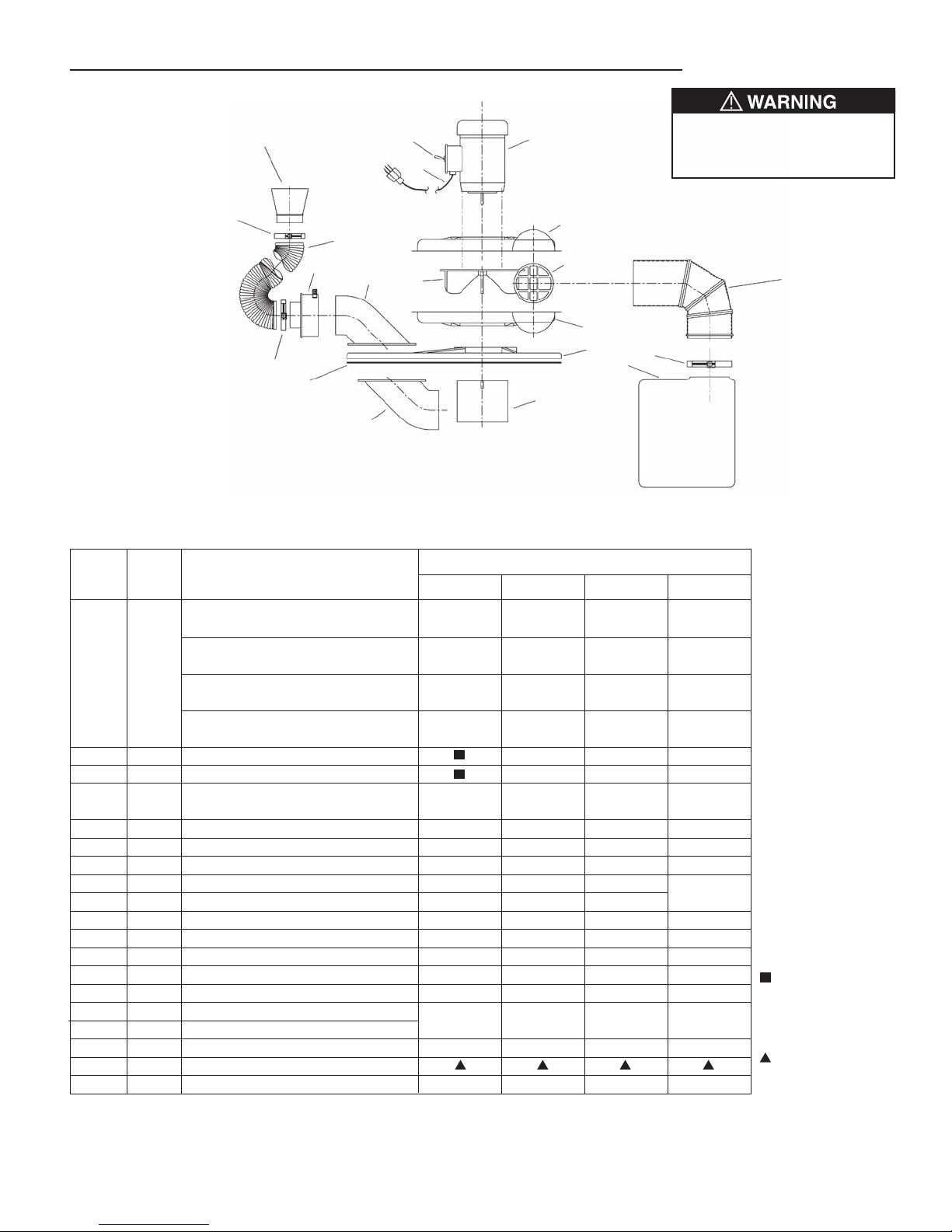
13
13
11
14
8
2
4
9
19
10
18
6
7
5
16A
15
16B
1
3
12
Ref.
No.
Qty.
Unit
Description
Part Number for Model
Standard Replacement Parts List for Models 100S, 150S, 200S and 300S
100S 150S 200S 300S (1)
NOTES
(1) Model 300S always
requires an oversized
dust bag. See page 14
for the oversized bags
and bag connector
parts.
(2) Includes 8 foot cord,
switch and 3 prong
grounded plug for use
on 115Volt, 1 Phase,
60 Hertz power supply
only.
(3) This motor is a 145TC
frame All other motors
are 56C frame.
(4) Price includes both
sides of stamped steel
blower housing with an
ABS discharge guard.
This is only sold as a
complete assembly for
liability reasons. Only
the discharge guard
(5) can be purchased
separately.
Must be purchased
from the local motor
manufacturers repair
shop for the motor
brand on your unit.
Standard hardware
store item. Purchase
locally.
Motor, 1 Phase, 115/230 Volt, 37755
373175 373677 N/A
60 Hz., 56C, TEFC (2)
Motor, 3 Phase, 230/460 Volt,
37254 37304 37353
374155
60 Hz., 56C, TEFC (3)
1 1
Motor, 1 Phase, 115/230 Volt, 37252 373118 N/A N/A
60 Hz., 56C, EXP
Motor, 3 Phase, 230/460 Volt, 3725462 37305 37354 N/A
60 Hz., 56C, EXP
2 1 Switch, 115 Volt, TEFC only — — —
3 1 Cord & Plug, 115 Volt, 60 Hz. only — — —
4,5 & 7 1 Blower Housing & Guard Assy.
34029DC 34029DC 34029DC 34029DC
(See note 4 at right)
5 1 Discharge Guard (only) 29318 29318 29318 29318
6 1 Blower Wheel 5530602 5500702 5501002 5510304
8 1 Discharge Elbow 51228 51228 51228 —
9 1 Dust Bag Clamp 31244 31244 31244 See page
10 1 Dust Bag 25071 25071 25071 14
11 1 Drum Lid 12060 12060 12060 12060
12 1 Inlet Nozzle, Square 51016 51017 51017 51017
13 2 Nozzle & Hose Clamp 31016 31244 31244 31244
14 1 Hose, Inlet, 60" long 31625PP 31626PP 31626PP 31626PP
15 1 Inlet Reducer 51110 — — —
16A 1 Inlet Elbow
12061 12061 12061 12061
16B 1 Inlet Deflector
17 1 Does not apply to these models — — — —
18 1 Lid Gasket
19 1 Intake Cylinder/Guard 51074G 51074G 51074G 51074G
X. Exploded View Drawing Parts List for Models 100S, 150S, 200S and 300S
Fig. 2
Part numbers 5, 8, 9, 10 and 19
must be in place at all times
during operation.
13
Page 14
4
6
4
5
3
2
1
Hanging
Bag
10
9
9
8
7
Drum
Bag
drum
not included
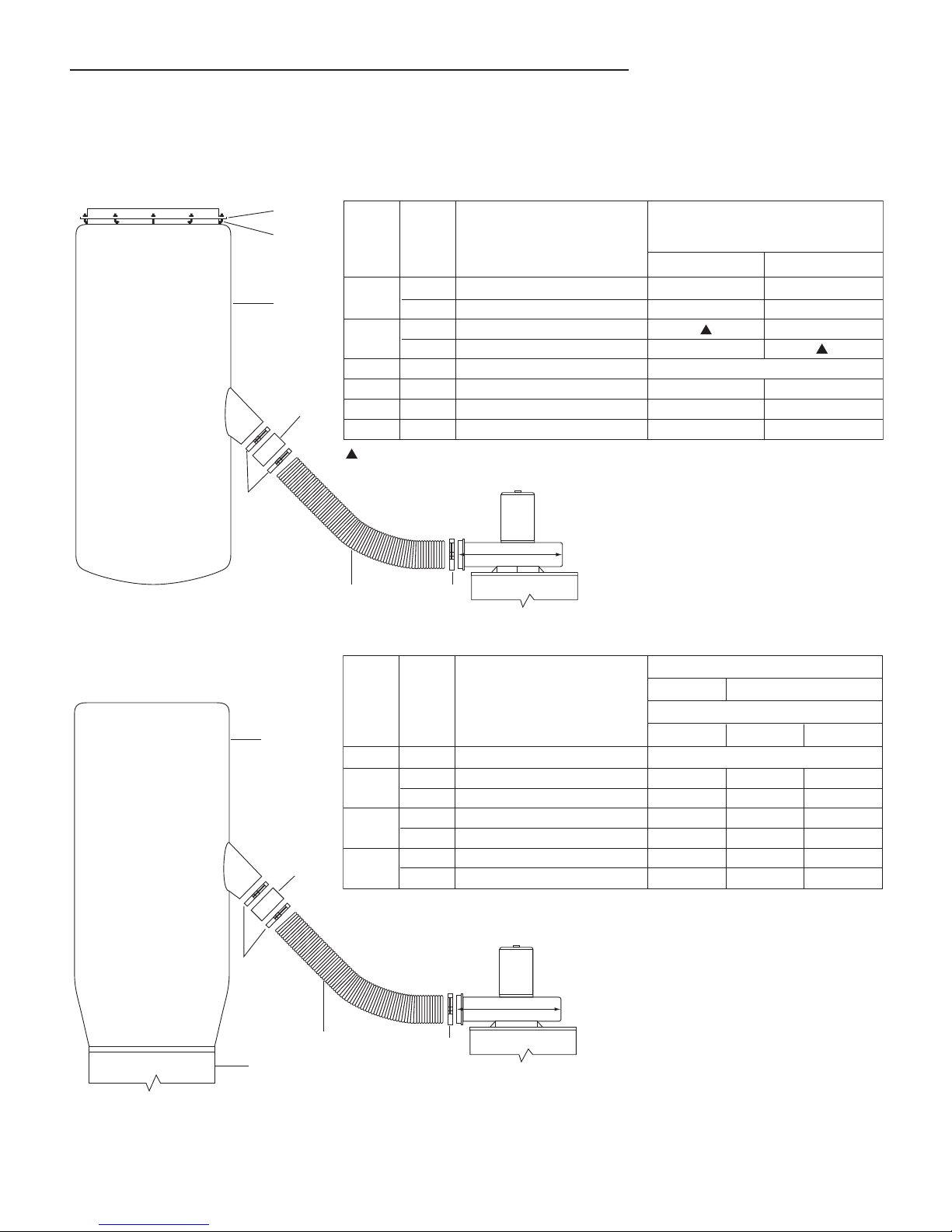
XI. Typical Oversized Dust Bag Connection Diagrams for Model 300S
Ref.
No. Qty.
Description
For Dust Collector
Parts List for #DB-24X40, #DB-24X80 and #DB-48X80 Drum Bags
50S & 75S
#DB-24X40 #DB-24X80 #DB-48X80
#100S to 300S
Bag Type
Ref. Numbers 8, 9 and 10 (for 6" hose) come as standard parts with all Model 300S.
7 1 Dust Bag, DB Type Select material type from catalog.
8
1 Hose Connector, 4" 51086 — —
1 Hose Connector, 6" — 51088 51088
9
3 Hose Clamps, 4" 31379 — —
3 Hose Clamps, 6" — 31244 31244
10
1 Hose, 4" dia. x 60" long 31623PP — —
1 Hose, 6" dia. x 60" long — 31626PP 31626PP
Ref.
No. Qty. Description
For Dust Collector
Parts List for #HB-24X80 and #HB-48X80 Hanging Bags
#HB-24X80 #HB-48X80
100S to 300S Bag Type
1
1 Ring, 24" Dia., 6 holes 27131 —
1 Ring, 48" Dia., 12 holes — 27123
2
6 J Hooks with 1/4-20 nuts —
12 J Hooks with 1/4-20 nuts —
3 1 Dust Bag, HB Type Select material type from catalog
4 3 Hose Clamps, 6" 31244 31244
5 1 Hose Connector, 6" 51088 51088
6 1 Hose, 6" dia. x 60" long 31626PP 31626PP
Standard hardware store items available locally.
Ref. Numbers 4, 5 & 6 (for 6” hose) come as standard parts with all Model 300S.
OPTIONAL FOR MODELS 50S, 75S, 100S, 150S, & 200S
NOTE: DUST BAG FOR MODEL 300S MUST BE ORDERED WITH THE DUST COLLECTOR
Fig. 3 “HB” Type Dust Bags
Fig. 4 “DB” Type Dust Bags
14
Page 15
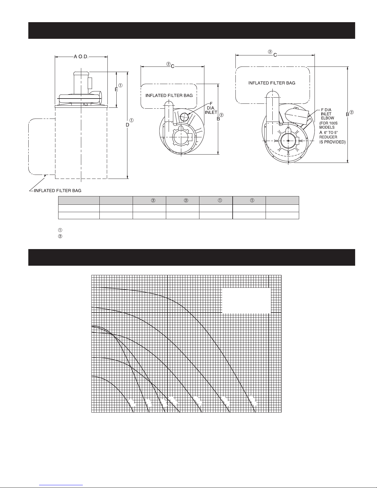
XIII. Dimensions and Performance Curves
TOP VIEW
100S-200S
TOP VIEW
33S-75S
FRONT VIEW
MODEL A B C D E F
33S - 75S 20
7
/8 323/4 291/2 401/4 15 4
100S - 200S 24
1
/2 443/4 37 523/4 183/4 6
Model 300S dimensions are very similar to 200S dimensions except dust bag.
Max. normal dimensions shown, varies with motor.
Approximate dimensions with standard inflated dust bag.
200
2.0
4.0
6.0
8.0
10.0
400 600 800 1000 1200 1400
SP in Inches
33S
50S
75S
100S
150S
200S
300S
CFM
MODELS 33S THROUGH 300S
Performances shown
do not include any
additional external
pressure drop.
NOTE: All dimensions are approximate for reference only. Dimensions subject to change without notice.
Dust-Master Performance Curves
*
Models 33S to 200S
*
were tested with
standard bags per
page 6.
Model 300S was
tested with a
DB-48 x 80 bag.
All models with 5
feet of hose and
nozzle.
15
Page 16

XII. LIMITED WARRANTY:
Notice of any claim, including a claim for defect in material or workmanship, must be given to Seller in writing within 30 days after
receipt of the equipment or other products. Seller reserves the right to inspect any alleged defect at Purchaser’s facility before
any claim can be allowed and before adjustment, credit, allowance replacement or return will be authorized. See RETURNS
below. Seller’s liability with respect to such defects will be limited to the replacement, free of charge, of parts returned at
Purchaser’s expense F.O.B. Seller’s plant and found to be defective by the Seller.
IN NO EVENT WILL SELLER BE LIABLE FOR SPECIAL, INDIRECT, INCIDENTAL OR CONSEQUENTIAL DAMAGES,
WHETHER IN CONTACT, TORT, NEGLIGENCE, STRICT LIABILITY OR OTHERWISE, INCLUDING WITHOUT LIMITATION
DAMAGES FOR INJURY TO PERSONS OR PROPERTY, LOST PROFITS OR REVENUE, LOST SALES OR LOSS OF USE
OF ANY PRODUCT SOLD HEREUNDER. PURCHASER’S SOLE AND EXCLUSIVE REMEDY AGAINST SELLER WILL BE
THE REPLACEMENT OF DEFECTIVE PARTS AS PROVIDED HEREIN OR REFUND OF THE PURCHASE PRICE FOR
DEFECTIVE PRODUCTS, AT SELLER’S SOLE OPTION. SELLER’S LIABILITY ON ANY CLAIM, WHETHER IN CONTRACT,
TORT, NEGLIGENCE, STRICT LIABILITY OR
OTHERWISE, FOR ANY LOSS OR DAMAGE ARISING OUT OF OR IN CONNECTION WITH PURCHASER’S ORDER OR THE PRODUCTS OR EQUIPMENT PURCHASED HEREUNDER, SHALL IN NO
CASE EXCEED THE PURCHASE PRICE OF THE EQUIPMENT GIVING RISE TO THE CLAIM.
RESPONSIBILITY:
It is the understanding of the Seller that Purchaser and/or User will use this equipment in conjunction with additional equipment
or accessories to comply with all Federal, State and local regulations. The Seller assumes no responsibility for the Purchaser’s
and/or User’s compliance with any Federal, State and local regulations.
RETURNS:
Cincinnati Fan & Ventilator Company assumes no responsibility for any material returned to our plant without our permission. An
RMA (Return Material Authorization) number must be obtained and clearly shown on the outside of the carton or crate and on a
packing slip. Any items returned must be shipped freight prepaid. Failure to comply will result in refusal of the shipment at our
receiving department.
7697 Snider Road
Mason, OH 45040-9135
www.cincinnatifan.com for more information
16
1M-0811, ADV.
Cincinnati Fan & Ventilator Company (Seller) warrants products of its own manufacture, against defects of material and workmanship under normal use and service for a period of eighteen (18) months from date of shipment or twelve (12) months from date of
installation, whichever occurs first. This warranty does not apply to any of Seller’s products or any part thereof which has been
subject to extraordinary wear and tear, improper installation, accident, abuse, misuse, overloading, negligence or alteration. This
warranty does not cover systems or materials not of Seller’s manufacture. On products furnished by Seller, but manufactured by
others, such as motors, Seller extends the same warranty as Seller received from the manufacturer thereof. Expenses incurred
by Purchaser’s in repairing or replacing any defective product will not be allowed except where authorized in writing and signed
by an officer of the Seller.
The obligation of the Seller under this warranty shall be limited to repairing or replacing F.O.B. the Seller’s plant, or allowing credit
at Seller’s option. THIS WARRANTY IS EXPRESSLY IN LIEU OF ALL OTHER WARRANTIES EITHER EXPRESSED OR
IMPLIED INCLUDING THE WARRANTIES OF MERCHANTABILITY AND FITNESS FOR A PARTICULAR PURPOSE AND OF
ALL OTHER OBLIGATIONS AND LIABILITIES OF THE SELLER. THE PURCHASER ACKNOWLEDGES THAT NO OTHER
REPRESENTATIONS WERE MADE TO PURCHASER OR RELIED UPON BY PURCHASER WITH RESPECT TO THE QUALITY OR FUNCTION OF THE PRODUCTS HEREIN SOLD.
Removal of the Sellers nameplate or any generic fan nameplate containing the fan serial number voids all warranties, either written or implied. Failure to complete and document all the pre-startup and post startup checks and perform the suggested routine
maintenance checks voids all warranties, either written or implied.
LIMITATION OF LIABILITY:
DISCLAIMER
This manual, and all its content herein, is based on all applicable known material at the time this manual was created. Any
parts of this manual are subject to change at any time and without notice.
If any statements, diagrams and/or instructions contained herein, for components not manufactured by the Seller, conflict
with instructions in the manufacturer’s manual (i.e.: motors), the instructions in the manufacturer’s
take precedent.
Should you want the latest version of this manual, please contact us or our sales office for your area. Or, you can print a current
version by going to our website at: www.cincinnatifan.com
manual, for that component
 Loading...