

Page 1

This Datasheet for the
IC660BBA026
Block 24/48Vdc Analog Current Source 6 Inputs
http://www.cimtecautomation.com/parts/p-14421-ic660bba026.aspx
Provides the wiring diagrams and installation guidelines for this GE Series 90-30
module.
For further information, please contact Cimtec Technical Support at
1-866-599-6507
Page 2
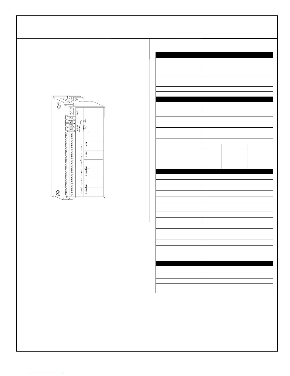
Current-source Analog Output Blocks
June 2002 GFK-0691D
Description ___________________________________
Current Source Input Blocks are used to interface a controller to
devices that provide 4mA to 20mA analog signals. Two Currentsource Input Blocks are available:
115VAC/125VDC Current-source Analog Input Block
(IC66*BBA106).
24/48VDC Current-source Analog Input Block
(IC66*BBA026).
These blocks are identical except for the power supply.
Current Source
Analog Input
(24 / 48 VDC
.7A Max)
Inputs: 24VDC
25mA
GND
H
N
+BSM
-BSM
EXC
IN
COM
GND
EXC
IN
COM
EXC
IN
COM
GND
EXC
IN
COM
GND
EXC
IN
COM
GND
EXC
IN
COM
GND
Features
Block features include:
Six 4-to-20 mA input circuits
Isolated channels
No user calibration required for operation
Software configurable
Advanced diagnostics
Dedicated Bus Switching Module control
A Current Source Input block has six 4-to-20mA current inputs.
Each input provides a 24 volt current loop power supply and is
isolated from all other circuits within the block. The BSM circuitry is
electrically common to Input 1, but isolated from the other inputs.
All circuits on the block support independent selection of linear
scaling values. These values can be used to convert the internal
values into engineering units suitable for the application.
Block diagnostics include:
low and high alarm reporting
overrange and underrange detection
open wire detection
internal fault reporting
A dedicated digital output is provided to drive a Bus Switching
Module (version IC66*BSM021 only).
Specifications _________________________________
Catalog Numbers
115 VAC/125 VDC Current
Source Analog Input Block IC66*BBA106
Terminal Assembly IC66*TBA106
Electronics Assembly IC66*EBA106
24/48 VDC Current Source
Analog Input Block IC66*BBA026
Terminal Assembly IC66*TBA026
Electronics Assembly IC66*EBA026
Block Specifications
Size (height x width x depth) 8.83” (22.44cm) x 3.56” (9.05cm)
Weight 4 lbs. (1.8 kg)
LEDs (I/O Block) Unit OK, I/O Enabled
BSM Control Switches one 24/48 VDC BSM (IC66*BSM021)
Block to Block Isolation 1500V for one minute
Group to Group Isolation 1500V RMS
Heat Dissipation 12 Watts maximum
Block Power (nominal); 115VAC 125VDC 24/4 VDC
Power supply voltage
Maximum current
Frequency/ripple
PS dropout time
Input Specifications
Input accuracy at 25° C 0.1% of full scale reading *
Input resolution 1µA
Input conversion time 16.6ms to 400ms (user selectable)
Range 4mA to 20mA
Overrange capacity 0mA to 25mA
Input diagnostics Underrange, Overrange, High Alarm, Low Alarm,
Channel to channel isolation 1500V RMS
Thermal drift (from 25°C) 70 PPM per degree C typical
Input Impedance 100 Ohms +/-5%
Normal Mode Rejection -45dB at 50, 60Hz
Input Excitation Characteristics
Open circuit voltage 24VDC
Short circuit current <75mA
Loop impedance 1000 Ohms maximum (0mA to 20mA),
Environmental Specifications
Operating temperature 0° C to +60° C (+32° to +140° F)
Storage temperature -40° to +100° C (-40° to +212° F)
Humidity 5% to 95% (non-condensing)
Vibration 5-10 Hz 0.2” (5.08mm) displacement,
Refer to GFK-0867 for product standards and general specifications.
* In the presence of severe RF interference (IEC 801-3, 10 V/m),
accuracy may be degraded to +/-0.25% of full scale reading.
x 4.42” (11.23cm)
98-132 VAC
250mA
47-63 Hz
1 cycle
105-145 VDC
140mA
10% max. ripple
10 ms min.
18-56
700mA
10% max. ripple
10ms min.
Open Wire
800 Ohms maximum (20mA to 25mA)
10-200 Hz at 1G
1
Page 3
Current-source Analog Output Blocks
June 2002 GFK-0691D
Using this Datasheet ____________________________
This datasheet summarizes information about block installation,
configuration, and diagnostics.
Your primary reference should be the Discrete and Analog Blocks
User’s Manual. It includes detailed instructions for block installation
and configuration.
For additional information about systems and communications,
including bus specifications, refer to the I/O System and
Communications Manual.
Compatibility __________________________________
Current Source Input blocks require a phase B Hand-held Monitor
(IC66*HHM501H, version 4.5 or later) for configuration.
For an IC697 series PLC, the programming software must be
version 3.0 or later. Bus controller IC697BEM731C or later is
required.
For an IC600 series PLC, the CPU must be rev. 105 or later. For an
IC600 series “Plus” PLC, rev. 110 or later is required. The
programming software must be rel. 4.02 or later. These blocks are
compatible with bus controllers IC66*CCBB902 and 903. They are
not compatible with bus controllers IC66*CBB900 and 901.
For an IC550 series PLC, the CPU must be rev. 3.0 or later. The
programming software must be rel. 2.01 or later.
If a Bus Switching Module will be attached directly to the block, it
must be the 24/48 VDC version (IC66*BSM021).
Installation Instructions _________________________
Carefully inspect all shipping containers for damage. If any
equipment is damaged, notify the delivery service immediately. Save
the damaged shipping container for inspection by the delivery
service. After unpacking the equipment, record all serial numbers.
Save the shipping containers and packing material in case it is
necessary to transport or ship any part of the system.
Block Mounting
Genius I/O blocks are considered "open equipment" and therefore
must be installed within a protective enclosure. They should be
located in an area that is clean and free of airborne contaminants.
There should be adequate cooling airflow.
The block can be mounted right side up, or upside down. Leave at
least 2 inches of space between blocks. Mount the block by drilling
two screw or bolt holes for 8-32 hardware. Position the block so that
the notches in the upper and lower flanges line up with the mounting
holes. Mount the block using 8-32 screws. Use star washers to
provide ground integrity.
Grounding
The block’s mounting screws must not be used as the only means of
grounding the block. Connect the green ground screw on the block to a
reliable ground system using a short wire lead, minimum size AWG #12
(avg 3.3mm2 in cross-section).
Warning
If mounting screws do not make good ground connection and
the ground screw is not connected to a reliable ground, the
block is not grounded. Electrical shock hazard exists. Death or
personal injury may result.
Block Wiring __________________________________
Do not overtorque the terminal screws. Recommended torque for all
terminals is 6 in/lb (.678 N/M).
Serial Bus Wiring
Terminals 1 to 4 are for the serial bus. These terminals accept one
AWG #12 wire (avg 3.3mm
(each avg 2.1mm
2
in cross-section). The minimum recommended wire
size is AWG #22 (avg .36mm
Terminals 1 - 4 can also accommodate spade or ring terminals up to
0.27 inch (6.85mm) wide with a minimum opening for a #6 screw, and up
to 0.20 inch (5.1mm) depth from the screw center to the back barrier.
Be sure unshielded wire ends are not longer than 2 inches (5 cm).
Using one of the cable types recommended in the System and
Communications User’s Manual, connect the serial bus to terminals 1- 4.
(If the block will control a Bus Switching Module, see below instead.)
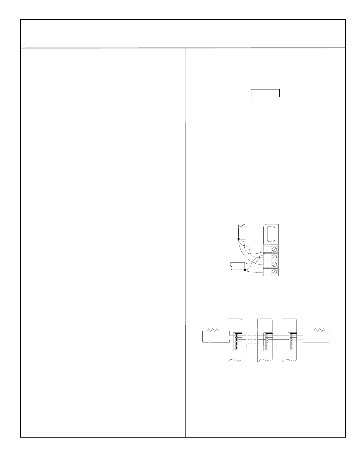
If the block is at either end of the bus, connect a terminating resistor of
the appropriate type (see the System and Communications User’s
Manual for details) across its Serial 1 and Serial 2 terminals.
Start
Terminating
Resistor
of Bus
2
cross-section) or two AWG #14 wires
2
in cross-section).
1
SERIAL 1
2
SERIAL 2
3
SHIELD IN
4
SHIELD OUT
End
of Bus
Terminating
Resistor
Serial 1
Serial 2
Shield In
Shield Out
Serial 1
Serial 2
Shield In
Shield Out
Connecting a Bus Switching Module
If the block will control a Bus Switching Module, install the BSM at
terminals 1-4, as shown on the next page. Connect the serial bus cables
to the BSM as described in the Bus Switching Module datasheet. Wire
either BSM pigtail wire to terminal 8 on the block, and the other to
terminal 9.
2
Page 4
Current-source Analog Output Blocks
June 2002 GFK-0691D
Field Wiring ___________________________________
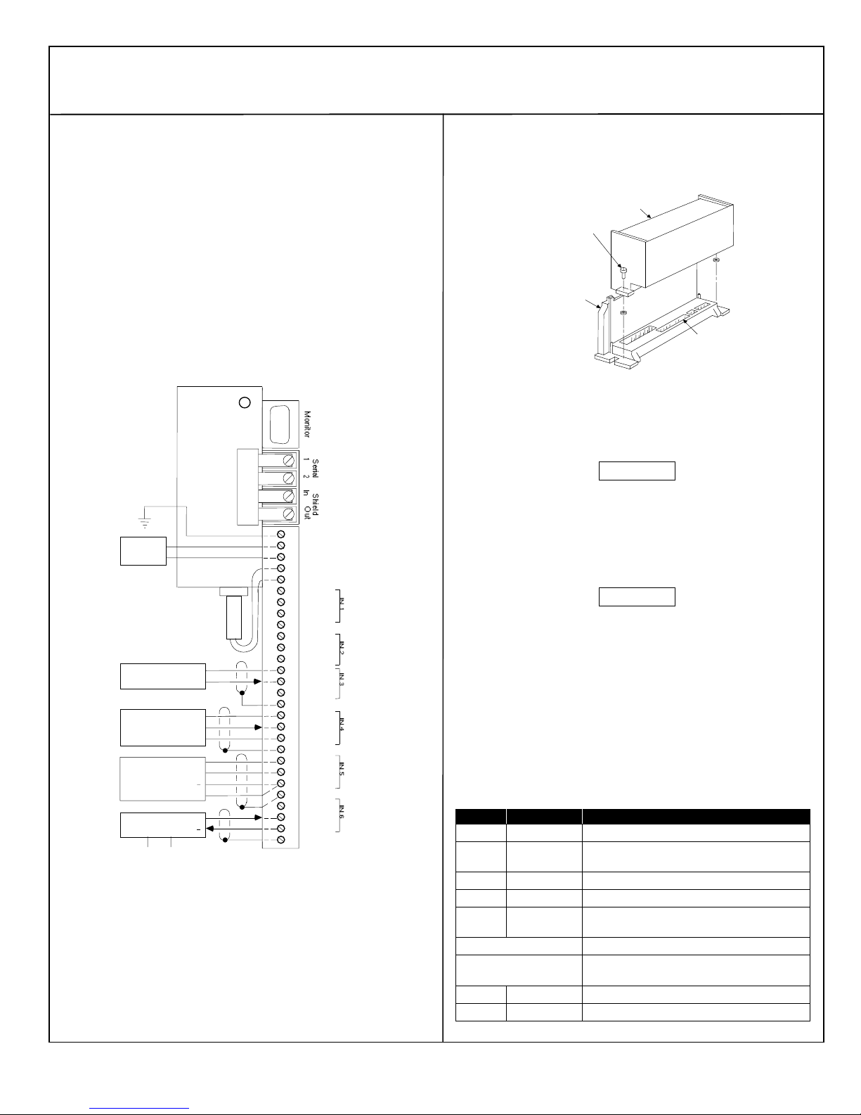
Terminals 5 to 32 are for field devices. They take a single wire up to
AWG #14 (avg 2.1mm
size is AWG #20 (avg .54mm
The ground (GND) terminal (5) is for block safety. It is connected to
the block chassis, and to terminals 13, 20, 24, 28, and 32. These
terminals, which are marked GND, are for shield termination, if
desired.
Self-powered or externally-powered transmitters are wired differently
from those powered by the block.
Wiring for Block Power
For block power, connect an appropriate power source to terminals 6
and 7. For AC block power, connect the source to the H terminal
and neutral to the N terminal. For DC block power, connect the
source to the DC+ terminal and the return to the DC- terminal.
Power
2 Wire Circuit
3 Wire Circuit
Transmitter
DC Power Source
2
Transmitter
4 Wire Circuit
Transmitter
4 Wire Circuit
Transmitter
DC+ DC-
in cross-section). Minimum recommended
2
in cross-section).
BSM
5
GND
6
H or DC+
7
N or DC-
8
+BSM
9
-BSM
10
EXC
IN
11
COM
12
GND
13
EXC
14
IN
15
COM
16
EXC
17
IN
18
COM
19
GND
20
21
EXC
IN
22
COM
23
GND
24
25
EXC
IN
26
COM
27
GND
28
EXC
29
IN
30
COM
31
32
GND
PWR
OUT
COM
DC+
+
-
+
DC-
+
Removing an Electronics Assembly ______________
The block’s Electronics Assembly can be replaced with a compatible
model without removing field wiring or reconfiguring the block.
Electronics
Assembly
Retaining
Screws
(Qty. 2)
Terminal
Assembly
Connector
Pins
1. Unscrew the retaining screws at the top and bottom of the block.
2. Using a Block Puller (IC660BLM507), engage the tabs in the first
vent slots. Move the tool to the center of the block and squeeze the
handle.
3. Pull the Electronics Assembly upward.
Warning
If power is applied to the field terminals, power is also exposed
on the connector pins at the base of the Terminal Assembly,
and electrical shock hazard exists. Do not touch the connector
pins! Death or injury may result.
Inserting an Electronics Assembly
1. Align the Electronics Assembly in the guides and push down firmly.
Caution
Do not exert excessive force; it may damage the block.
2. If unusual resistance is met, remove the Electronics Assembly. If
power is applied to the block, DO NOT TOUCH THE CONNECTOR
PINS! Inspect the Terminal Assembly, connector receptacle, and
connector edge board (on the Electronics Assembly). Be sure the
keying matches. Remove any obstacles and reinsert the
Electronics Assembly. Pay close attention to the alignment of the
guide pins.
3. Secure the Electronics Assembly with the screws on the top and
bottom of the Terminal Assembly.
LEDs ________________________________________
The block's Unit OK and I/O Enabled LEDs show its operating status.
Unit OK I/O Enabled Meaning
ON ON Block functioning, CPU communicating
ON OFF Block functioning
ON Blinking Block functioning, Circuit forced
Blinking ON Circuit fault, CPU communicating
Blinking OFF Circuit fault
Alternate Blinking Circuit fault, Circuit forced
Synchronous
Blinking
OFF Blinking Electronics/Terminal Assembly mismatch
OFF OFF No block power, or block faulty
No CPU communications for 3 bus scans
No CPU communications for 3 bus scans
No CPU communications - block number
conflict
3
Page 5
Current-source Analog Output Blocks
June 2002 GFK-0691D
Block Operation ________________________________
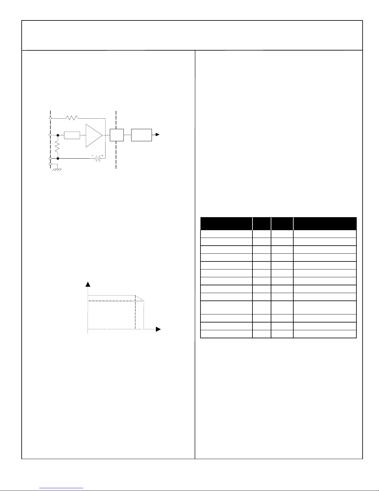
A Current-source Analog Input block has six independent inputs.
Input channels use voltage to frequency converters and counters to
translate analog currents to a digital value. This value is converted
by the block to engineering units before it is sent to the CPU. A
diagram of an input circuit is shown below.
EXC
IN
COM
GND
Each input circuit has a 24 volt current loop power supply, capable
of providing 25mA of current. Each input is isolated from all other
circuits on the block. Input accuracy is 0.1%. Input conversion time
can be selected to provide the appropriate combination of noise
rejection and input resolution. Conversion times are programmable
from 16ms to 400ms. Resolution increases as the conversion time
is lengthened. Input resolution is 1µA for 200ms conversion time.
Upper and lower alarm limits can be programmed for each input
circuit. If either limit is exceeded, the block indicates a fault and
sends a message to the Hand-held Monitor and CPU.
The following illustration shows the input excitation current derating
versus temperature. The maximum excitation current per channel is
25mA.
47
Opto
Isol.
100
Case
Ground
Filter
V to F
24VDC
maximum excitation current
per block in milliAmps
150
120
90
60
30
0 1020304050 6070
temperature in degrees C
16 Bit
Counter
Processor
Diagnostics _________________________________
The block’s advanced diagnostics provide the messages listed below.
Fault messages can be cleared from the Hand-held Monitor or the CPU.
Input Open Wire: Input current is below 2mA.
Input High Alarm: Input exceeds high alarm level.
Input Low Alarm: Input exceeds low alarm level.
Input Overrange: Signal exceeds 25mA.
Input Underrange: Current is negative, or 0mA.
Configuration _________________________________
First, the block must be configured with a Hand-held Monitor to:
Enter its Device Number (serial bus address).
Enter its Reference Number (required only for IC600 and IC550
series PLCs only).
The rest of the features can be configured either using a Hand-held
Monitor, or by sending a Write Configuration datagram to the block from
the host.
If a block is configured offline, it must be properly grounded and
Note:
have a 75 Ohm resistor installed across its Serial 1 and Serial 2
terminals. See the Discrete and Analog I/O Blocks User’s Manual for
instructions.
Feature Circuit
/Block
Device Number Block null 0 to 31 (must be selected)
Reference Address Block none Depends on host CPU type
Baud Rate, Kbd Block 153.6 std 153.6 std, 153.6 ext, 76.8, 38.4
Report Faults Circuit yes yes/no
Channel active Circuit active active/inactive
BSM Present Block no yes/no
BSM Controller Block no yes/no
CPU Redundancy Block none none/standby
Input conversion time Block 400ms 16 to 400ms
Input Scaling Circuit 1µA per
Low Alarm Circuit 0 +/-32767 eng. units
High Alarm Circuit +25000 +/-32767 eng. units
Configuration Protection Block disabled enabled, disabled
Factory
Setting
eng unit
Selections
+/-32767 eng units
0 to +25000µA
4
 Loading...