

Page 1
TECHNICAL DATA SHEET
AUTOMATIC FLOW
technological solutions
BALANCING VALVE
790
PN 25
Main features:
Technical data:
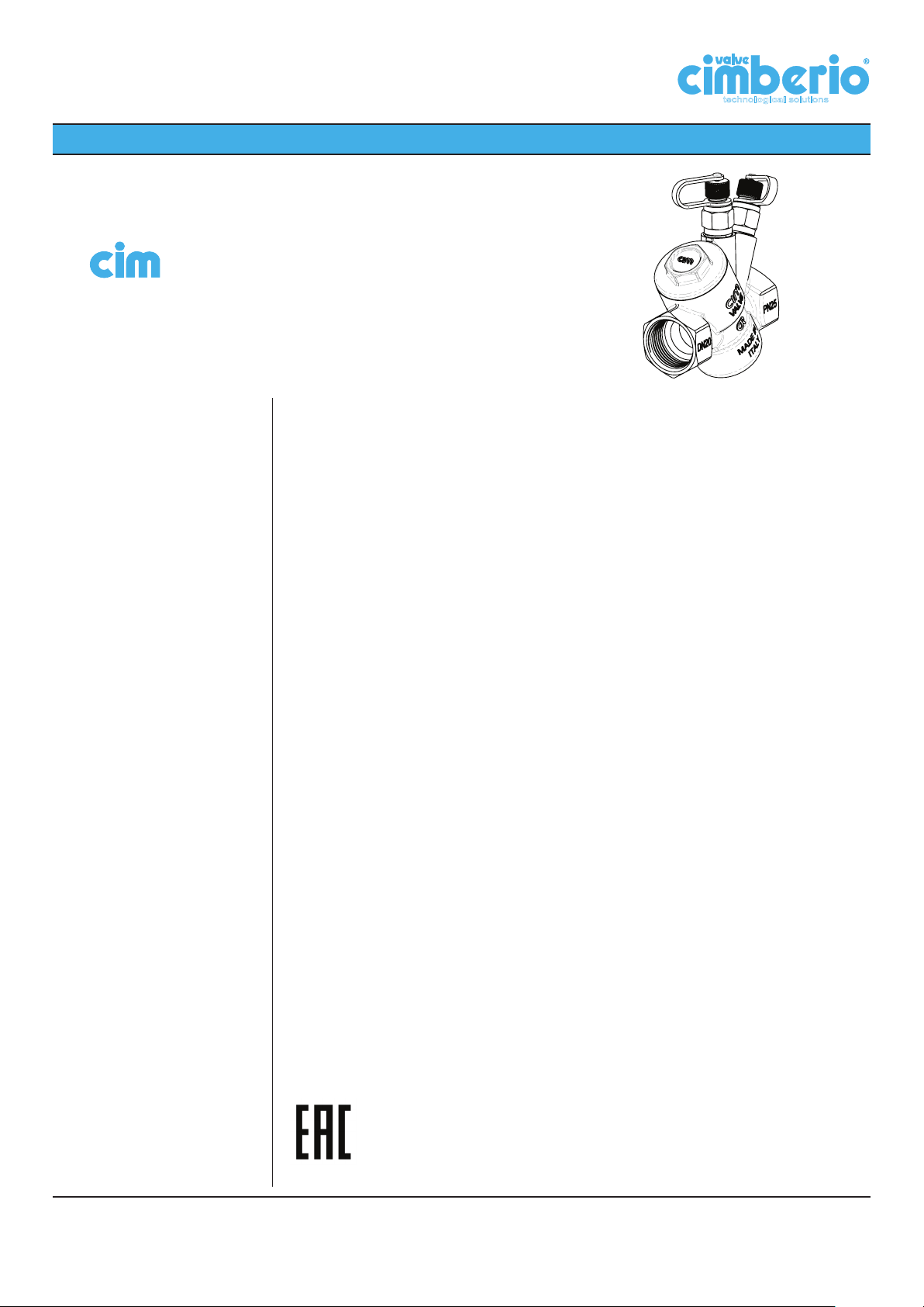
Cim 790 is used for balancing the flow in cooling, heating and domestic water systems.
Cim 790 is an automatic balancing valve with following features:
• Constant flow regardless system pressure fluctuations;
• System balancing is assured automatically, even under fluctuating pressure condi-
tions;
• Automatic balancing is achieved by means of cartridges that provide constant flow
within a fixed range of differential pressures;
• The self-cleaning cartridge design makes very difficult for any particles to accumulate
and compromise the accuracy of the valve.
It is supplied with internal thread.
It is made of “CR” brass (“CR” - Corrosion Resistant).
This article is made in compliance with the quality management requirements of ISO
9001:2008 standard.
All articles are tested according to the EN 12266-1:2003 standard.
It can be used in a wide variety of sectors: heating, air conditioning, water, sanitary systems
and generally with any non corrosive liquid.
Approved by:
Cav. Uff. Giacomo Cimberio S.p.A.
Max. static working pressure 25 bar
Max. flow temperature 120 °C
Min. temperature -20°C
Fluids: Water and Glycol
Material of parts in contact with water:
Valve body;
Cartridge, etc.
Materials:
“CR”Brass (EN 12165-CW602N-M)
O-rings: EPDM Perox
Threads: ISO 228
Rev. 3 del 03/2015
1
Page 2
TECHNICAL DATA SHEET
Models:
technological solutions
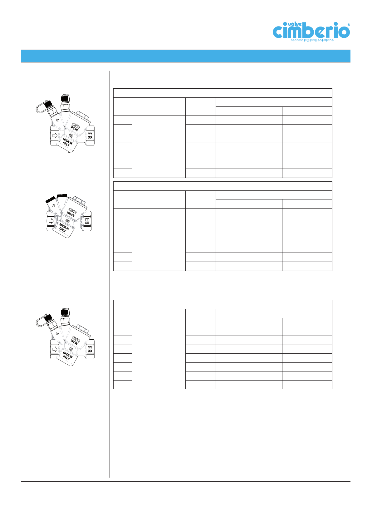
Cim 790 - Automatic balancing valve - PN 25 - “CR” Brass*
DN Material Thread
15
20 G. 3/4” 0.00694 ÷ 0.68 25 ÷ 2448 0.111 ÷ 10.78
25 G. 1” 0.00694 ÷ 0.68 25 ÷ 2448 0.111 ÷ 10.78
25L G. 1” 0.187 ÷ 3.15 674 ÷ 11355 2.97 ÷ 50.00
32 G. 1”1/4 0.187 ÷ 3.15 674 ÷ 11355 2.97 ÷ 50.00
40 G. 1”1/2 0.187 ÷ 3.15 674 ÷ 11355 2.97 ÷ 50.00
50 G. 2” 0.187 ÷ 3.15 674 ÷ 11355 2.97 ÷ 50.00
Cim 790/2P - Automatic balancing valve - PN 25 - “CR” Brass - without test points*
DN Material Thread
15
20 G. 3/4” 0.00694 ÷ 0.68 25 ÷ 2448 0.111 ÷ 10.78
25 G. 1” 0.00694 ÷ 0.68 25 ÷ 2448 0.111 ÷ 10.78
25L G. 1” 0.187 ÷ 3.15 674 ÷ 11355 2.97 ÷ 50.00
32 G. 1”1/4 0.187 ÷ 3.15 674 ÷ 11355 2.97 ÷ 50.00
40 G. 1”1/2 0.187 ÷ 3.15 674 ÷ 11355 2.97 ÷ 50.00
50 G. 2” 0.187 ÷ 3.15 674 ÷ 11355 2.97 ÷ 50.00
CR Brass
EN 12165-CW602N-M
CR Brass
EN 12165-CW602N-M
G. 1/2” 0.00694 ÷ 0.68 25 ÷ 2448 0.111 ÷ 10.78
G. 1/2” 0.00694 ÷ 0.68 25 ÷ 2448 0.111 ÷ 10.78
(l/s) (l/h) (GPM)
(l/s) (l/h) (GPM)
Flow rate range
Flow rate range
* The valve is supplied with the cartridge already installed. For orders specify the
code of the required cartridge in accordance with the attached tables.
Cim 790B - Automatic balancing valve - PN 25 - “CR” Brass - without cartridge
DN Material Thread
15
20 G. 3/4” 0.00694 ÷ 0.68 25 ÷ 2448 0.111 ÷ 10.78
25 G. 1” 0.00694 ÷ 0.68 25 ÷ 2448 0.111 ÷ 10.78
25L G. 1” 0.187 ÷ 3.15 674 ÷ 11355 2.97 ÷ 50.00
32 G. 1”1/4 0.187 ÷ 3.15 674 ÷ 11355 2.97 ÷ 50.00
40 G. 1”1/2 0.187 ÷ 3.15 674 ÷ 11355 2.97 ÷ 50.00
50 G. 2” 0.187 ÷ 3.15 674 ÷ 11355 2.97 ÷ 50.00
CR Brass
EN 12165-CW602N-M
G. 1/2” 0.00694 ÷ 0.68 25 ÷ 2448 0.111 ÷ 10.78
(l/s) (l/h) (GPM)
Flow rate range
Cav. Uff. Giacomo Cimberio S.p.A.
2
Page 3
TECHNICAL DATA SHEET
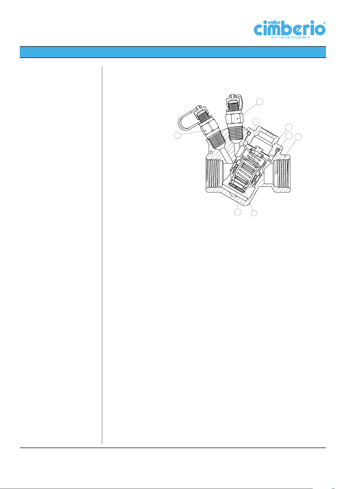
Cross section:
technological solutions
Installation procedure:
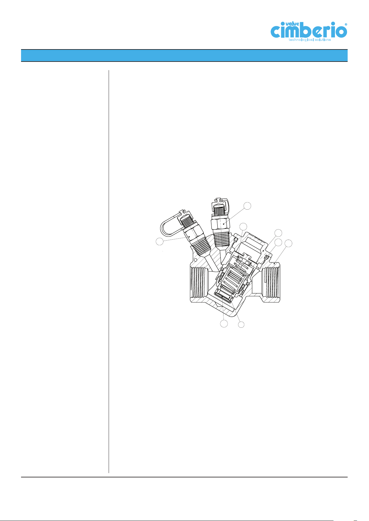
1. Valve body
2. Cartridge
3. Orifice
4. Elastic ring
5. O-ring
6. Plug
7. Blue binder point
8. Red binder point
7
2
6
8
4
3
5
1
Before installation of Cim 790, check that inside the valve and the pipes there are no foreign
matters which might damage the tightness of the valve.
Burr pipe connections after having threaded them and distribute the sealing material on
pipe threads only and not on valve threads.
It is advisable to install a filter and an intercepting valve on the feed line.
Before installation of Cim 790, check that cartridge flow rate is properly matching the project requirements and that pump is able to assure the minimum differential pressure (Δp
min) stated in the tables of following pages (section “Tables”).
Valves may be installed either on horizontal or vertical pipelines, following the arrow direction casted on the valve body, which shall be the same as the flow one.
For assembly purposes, use a spanner, not a pipe wrench, by applying necessary working torque only on the valve end nearest the pipe. This helps get a firmer grip and avoids
potential damages to valve body.
Make sure that pipe threading length is not longer than valve threads.
It is advisable to flush the installation before service. To this purpose, remove all cartridges
of the installed valves, following the instructions detailed in “Maintenance” part of the present brochure.
Cav. Uff. Giacomo Cimberio S.p.A.
3
Page 4
TECHNICAL DATA SHEET
→
Balancing:
Calibrated orifice
Typical installations:
technological solutions
Flow rate balancing is achieved automatically by Cim 790, regardless pressure fluctuations. The flow rate of each cartridge depends on the fixed orifice installed therein. Each
fixed orifice has a four digit code number,corresponding to the last four digits of Cimberio
cartridge code.
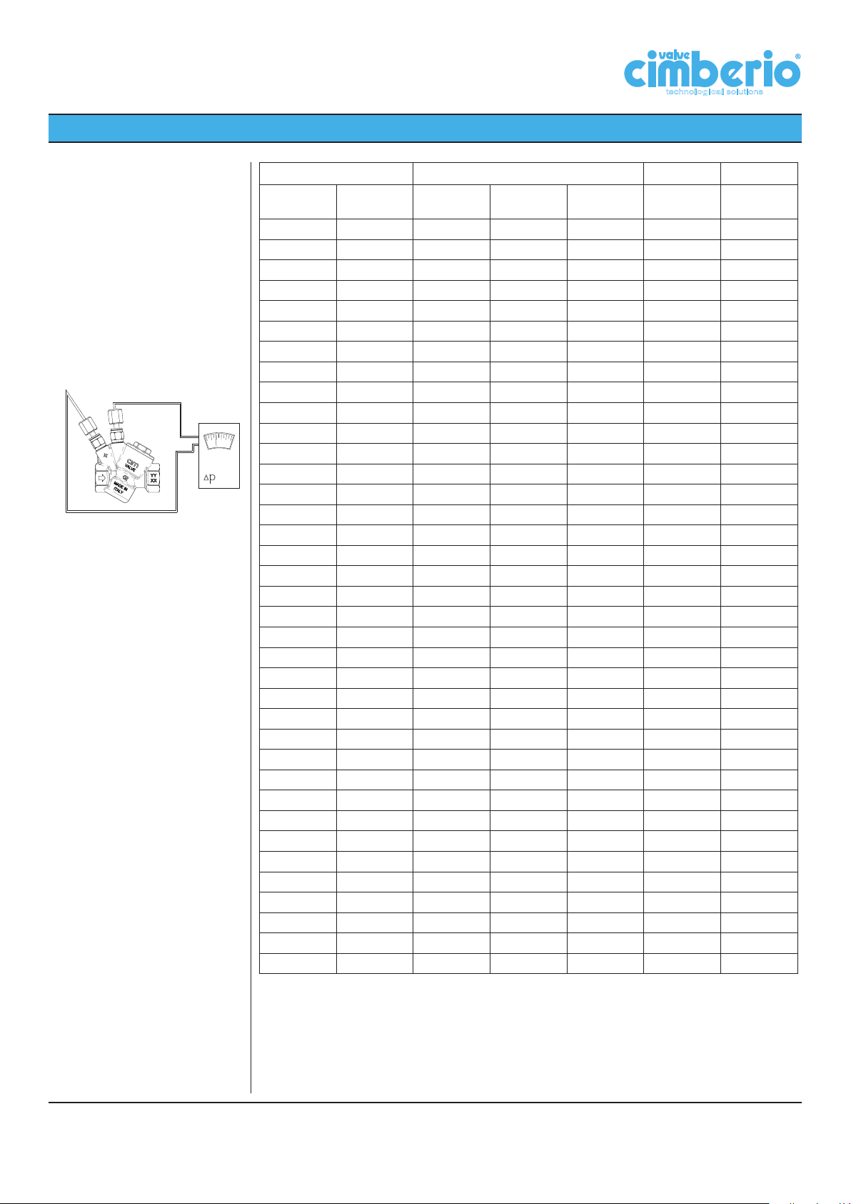
Once the cartridge is identified by Cimberio code, the relevant flow rates and minimum Δp
can be read in the tables shown in “Tables” section of this brochure.
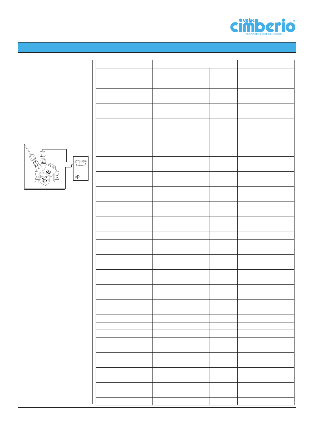
Using the electronic differential manometer Cim 726, check that the differential pressure is
higher or the same as the minimum value shown in said tables. The differential manometer
interfaces with the balancing valve through two sensors inserted in the binder points of the
valve.
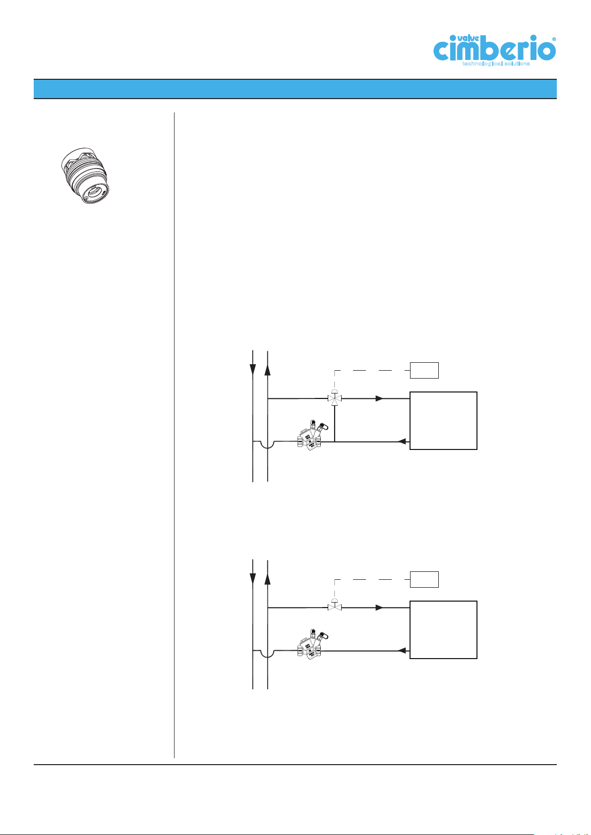
Cim 790 is suitable for constant volume system, where diverting or mixing valves are installed as fancoil control. Below a typical installation with a diverting valve: in each moment
the flow rate will result constant and there will not be extra-flow due to the pressure fluctuations introduced by the hidraulic shortcircuit that would be created when the flow goes
across the by-pass.
Controller
LOAD:
Power (kW)
Differential
temperature (°C)
The automatic flow balancing valves can also be used with variable speed pumps. By using a 2 ports control valve (ON/OFF), the flow in each emitters can be stopped as soon as
the desired room temperature in reached. In this way the branches that are still opened will
not be affected by the total flow variations. The effect is that there is an energy saving due
to the reduction of the total pumped flow.
Controller
LOAD:
Power (kW)
Differential
temperature (°C)
Cav. Uff. Giacomo Cimberio S.p.A.
4
Page 5
TECHNICAL DATA SHEET
Sizing:
K
vs
Kvs - Kv across the valve when it is
fully open (at start up pressure)
Relative density
Fluid r
Water 1.000
Water and glycol 10% 1.012
Water and glycol 20% 1.028
Water and glycol 30% 1.040
Water and glycol 40% 1.054
Water and glycol 50% 1.067
technological solutions
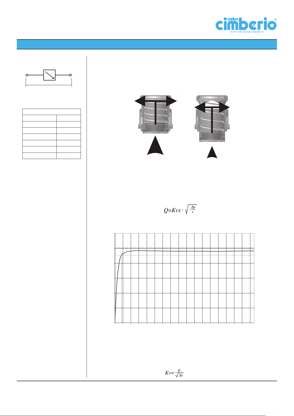
When the pressure increases, the spring is compressed and the piston reduces outlet windows, in order to maintain the same flow rate; when ∆p decreases the windows start to
open again (see picture on the right).
Constant flow is obtained through the valve, despite pressure fluctuations.
By simply measuring differential pressure across the valve, the flow through the cartridge
is obtained as follows:
• If measured differential pressure is above ∆p
(start-up pressure), the flow rate is the
min
same as the one stated on the cartridge table;
• If measured differential pressure is below minimum ∆p
stated on cartridge table,
min
flow rate is calculated with one of the following formula:
where:
Q is the flow rate in m
0.12
0.10
0.08
0.06
Flow rate - l/s
0.04
0.02
0
3
/h, r is the relative density, ∆p is the pressure drop across the valve .
∆p min
20 40 60 80 100 120 140 160 180 200 220 240 260 280 300 320 340
Differential pressure - kPa
FLOW COEFFICIENT
Kv, in metric system represents the flow in m3/h of water at the temperature of 15.5°C
(density =998 kg/m3) which causes a pressure drop of 1 bar. In the USA flow coefficient is
called Cv (Kv = 0.865 Cv).
Cav. Uff. Giacomo Cimberio S.p.A.
5
Page 6
TECHNICAL DATA SHEET
Δ
p
m
technological solutions
Q
c
p
Δ
Δ
p
a
=
Δ
p
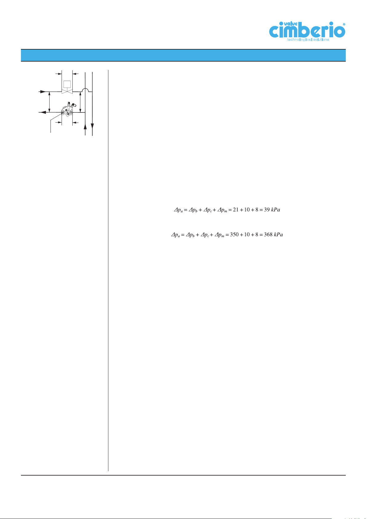
Pressure drop across Cim 790
b
Δ
p
Pressure drop across the control valve
m
Δ
p
Circuit pressure drop
c
Δ
p
Available pressure for the riser
a
a
p
Δ
Δ
p
b
Δpb + Δpc + Δp
m
SUGGESTED VALUES AND TIPS:
• Velocities in the pipeline:
Max = 1.15 m/s
Min = 0.75 m/s
For the preliminary sizings where the
value of maximum available pressure is
not known, it is possible to use the maximum head of the pump directly.
EXAMPLE
It is required to balance the circuit in the figure, the given data are:
• Circuit pressure drop: ∆pc=10 kPa;
• Pressure drop across the control valve: ∆pm= 8 kPa;
• Flow rate: Q= 3.2 m3/h=0.889 l/s;
• Maximum head: ∆p
= 60 kPa (Pump head);
a,max
• Pipeline size: DN 32.
It is possible to install a valve with the same diameter of the pipe, to avoid fittings installation. Using a Cim 790 DN32, it is possible to select from the list of the installable cartridges
the closest value of nominal flow rate to the required one.
It is possible to install the cartridge CA3156 with nominal flow rate of 0.886 l/s (the error is
less than 2.5 %).
This cartridge needs at least 21 kPa of differential pressure in order to work properly, the
available pressure on the riser should be at least:
The maximum allowable differential pressure across the balancing valve is 350 kPa, it
means that the maximum head at the riser shall be:
Being the maximum head less than the calculated limit, the installation is correct.
If it wasn’t, it would be possible to install the high differential pressure version: CA3156H
(up to 600 kPa).
Cav. Uff. Giacomo Cimberio S.p.A.
6
Page 7
TECHNICAL DATA SHEET
Pressure
Len
FROM
MULTIPLY BY
TO OBTAIN
Pa, Pascal 0,001 kPa, kiloPascal
Pa, Pascal 0,000001 MPa, Mega Pascal
Pa, Pascal 0,00001 bar
Pa, Pascal 0,00010972 m
H2O
, metres of water
Pa, Pascal 0,000145038 psi, pound per square inch
bar 1,01325 atm, atmosphere
bar 0,980665
Kg/cm2, kilograms per square centimetre
bar 10,1972 m
H2O
, metres of water
bar 14,5038 psi, pound per square inch
atm, atmosphere 1,03323
Kg/cm2, kilograms per square centimetre
atm, atmosphere 10,3323 m
H2O
, metres of water
atm, atmosphere 14,6959 psi, pound per square inch
Kg/cm
2
10 m
H2O
, metres of water
Kg/cm
2
14,2233 psi, pound per square inch
m
H2O
1,42233 psi, pound per square inch
TO OBTAIN
DIVIDE BY
FROM
Measurement conversion
chart:
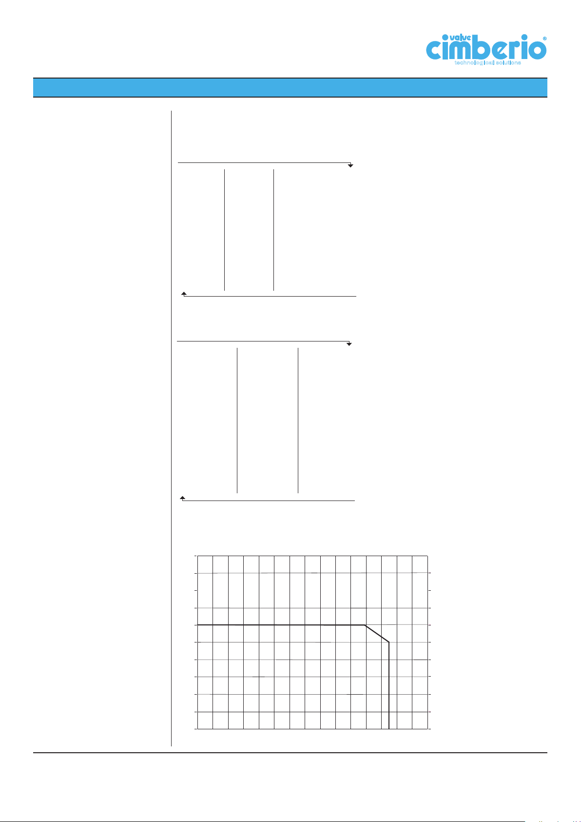
Pressure-temperature
ratings:
Pressure
FROM
MULTIPLY BY
Pa, Pascal 0,001 kPa, kiloPascal
Pa, Pascal 0,000001 MPa, Mega Pascal
Pa, Pascal 0,00001 bar
Pa, Pascal 0,00010972 m
Pa, Pascal 0,000145038 psi, pound per square inch
bar 1,01325 atm, atmosphere
bar 0,980665
bar 10,1972 m
bar 14,5038 psi, pound per square inch
atm, atmosphere 1,03323
atm, atmosphere 10,3323 m
atm, atmosphere 14,6959 psi, pound per square inch
2
Kg/cm
Kg/cm
m
H2O
TO OBTAIN
2
10 m
14,2233 psi, pound per square inch
1,42233 psi, pound per square inch
DIVIDE BY
, metres of water
H2O
Kg/cm2, kilograms per square centimetre
, metres of water
H2O
Kg/cm2, kilograms per square centimetre
, metres of water
H2O
, metres of water
H2O
gth, Area, Volume, Density
FROM MULTIPLY BY
inches 0,0254 m, metres
inches 2,54 cm, centimetres
feet 0,3048 m, metres
feet 30,48 cm, centimetres
yards 0,9144 m, metres
square inches 0,00064516 m
square feet 0,09290304 m
square inches 6,4516 cm
square feet 929,0304 cm
square yards 0,8361274 m
l, litres 0,001 m
gallons 0,003789412 m
cubic yards 0,7645549 m
cubic feet 0,02831685 m
cubic inches 0,0000164 m
cubic inches 16,38706 cm
cubic feet 28,31685 l, litres
gallons
TO OBTAIN
180
160
58 116 174 232 290 349
29
0
3,875412 l, litres
DIVIDE BY
87
TO OBTAIN
2
, metri quadrati
2
, square metres
2
, square centimetres
2
, square centimetres
2
, square metres
3
, cubic metres
3
, cubic metres
3
, cubic metres
3
, cubic metres
3
, cubic metres
3
, cubic centimetres
145 203 261 319
TO OBTAIN
FROM
FROM
technological solutions
2
p
[lbf/in ]
406
377
356
320
Cav. Uff. Giacomo Cimberio S.p.A.
140
120
100
T [°C]
80
60
40
20
0
0
4
8 12 16 20 24 282 6 10 14 18 22 26
p [bar]
284
248
212
T [°F]
176
140
104
38
32
7
Page 8
TECHNICAL DATA SHEET
technological solutions
Cartridges
DN 15, DN20, DN25
Cim 790
∆p ≥ ∆p
∆p < ∆p
--> Q = Q
min
--> Q = Kvs √ ∆p
min
nom
Cartridge code Flow rate
Max. 350
kPa
CA1150 - 0.007 25 0.11 7 0.09
CA1170 - 0.010 35 0.15 7 0.14
CA1190 CA1190H 0.012 46 0.20 7 0.16
CA1210 CA1210H 0.015 55 0.24 7 0.21
CA1230 CA1230H 0.021 75 0.33 8 0.27
CA1260 CA1260H 0.023 84 0.37 9 0.28
CA1290 CA1290H 0.029 104 0.46 10 0.33
CA1300 CA1300H 0.032 114 0.50 10 0.36
CA1320 CA1320H 0.036 129 0.57 11 0.39
CA1350 CA1350H 0.043 154 0.68 11 0.46
CA1370 CA1370H 0.049 175 0.77 12 0.51
CA1400 CA1400H 0.057 204 0.90 12 0.59
CA1430 CA1430H 0.067 241 1.06 12 0.70
CA1460 CA1460H 0.078 279 1.23 12 0.81
CA1490 CA1490H 0.089 320 1.41 13 0.89
CA1510 CA1510H 0.097 350 1.54 13 0.97
CA1540 CA1540H 0.111 400 1.76 13 1.11
CA1570 CA1570H 0.132 477 2.10 14 1.27
CA1620 CA1620H 0.151 545 2.40 14 1.46
CA1725 CA1725H 0.171 615 2.71 14 1.64
CA1730 CA1730H 0.186 670 2.95 14 1.79
CA1735 CA1735H 0.204 736 3.24 14 1.97
CA1740 CA1740H 0.222 799 3.52 16 2.00
CA1745 CA1745H 0.242 870 3.83 19 2.00
CA1750 CA1750H 0.260 936 4.12 21 2.01
CA2070 CA2070H 0.283 1020 4.49 22 2.17
CA2074 CA2074H 0.300 1081 4.76 22 2.30
CA2077 CA2077H 0.332 1195 5.26 22 2.55
CA2082 CA2082H 0.371 1335 5.88 23 2.78
CA2086 CA2086H 0.412 1438 6.53 23 3.09
CA2088 CA2088H 0.439 1581 6.96 23 3.30
CA2092 CA2092H 0.493 1774 7.81 24 3.62
CA2094 CA2094H 0.509 1833 8.07 24 3.74
CA2099 CA2099H 0.578 2080 9.16 25 4.16
CA2103 CA2103H 0.625 2251 9.91 26 4.41
CA2106 CA2106H 0.644 2319 10.21 27 4.46
CA2109 CA2109H 0.680 2448 10.78 28 4.63
Max. 600
kPa
l/s l/h GPM kPa (m
∆p
min
Kvs
3
/h)/bar
0.5
Cav. Uff. Giacomo Cimberio S.p.A.
8
Page 9
TECHNICAL DATA SHEET
technological solutions
Cartridges
DN 25L, DN32, DN40, DN 50
Cim 790
∆p ≥ ∆p
∆p < ∆p
--> Q = Q
min
--> Q = Kvs √ ∆p
min
nom
Cartridge code Flow rate
Max. 350
kPa
CA3073 CA3073H 0.187 674 2.97 12 1.95
CA3082 CA3082H 0.239 861 3.79 12 2.49
CA3089 CA3089H 0.283 1020 4.49 12 2.94
CA3094 CA3094H 0.315 1136 5.00 12 3.28
CA3096 CA3096H 0.331 1190 5.24 12 3.44
CA3098 CA3098H 0.353 1272 5.60 13 3.53
CA3102 CA3102H 0.375 1349 5.94 13 3.74
CA3107 CA3107H 0.413 1485 6.54 13 4.12
CA3111 CA3111H 0.435 1567 6.90 14 4.19
CA3112 CA3112H 0.453 1631 7.18 14 4.36
CA3118 CA3118H 0.504 1815 7.99 14 4.85
CA3124 CA3124H 0.556 2001 8.81 15 5.17
CA3125 CA3125H 0.568 2044 9.00 16 5.11
CA3129 CA3129H 0.603 2171 9.56 16 5.43
CA3132 CA3132H 0.631 2271 10.00 17 5.51
CA3135 CA3135H 0.661 2380 10.48 17 5.77
CA3138 CA3138H 0.694 2498 11.00 18 5.89
CA3142 CA3142H 0.733 2639 11.62 18 6.22
CA3148 CA3148H 0.797 2871 12.64 19 6.59
CA3156 CA3156H 0.886 3191 14.05 21 6.96
CA3161 CA3161H 0.946 3407 15.00 22 7.26
CA3163 CA3163H 0.968 3486 15.35 22 7.43
CA4148 CA4148H 1.009 3635 16.00 20 8.13
CA4152 CA4152H 1.023 3681 16.21 21 8.03
CA4156 CA4156H 1.136 4090 18.00 21 8.92
CA4164 CA4164H 1.199 4315 19.00 21 9.42
CA4168 CA4168H 1.262 4540 20.00 22 9.68
CA4173 CA4173H 1.325 4770 21.00 22 10.17
CA4176 CA4176H 1.388 4995 22.00 23 10.42
CA4182 CA4182H 1.514 5450 24.00 24 11.12
CA4191 CA4191H 1.640 5905 26.00 25 11.81
CA4194 CA4194H 1.816 6539 29.00 26 12.82
CA4200 CA4200H 1.893 6815 30.00 27 13.11
CA4205 CA4205H 2.019 7265 32.00 28 13.73
CA4211 CA4211H 2.145 7720 34.00 30 14.10
CA4217 CA4217H 2.271 8175 36.00 31 14.68
CA4222 CA4222H 2.397 8630 38.00 33 15.02
CA4229 CA4229H 2.523 9085 40.00 34 15.58
CA4235 CA4235H 2.650 9540 42.00 36 15.90
CA4241 CA4241H 2.776 9990 44.00 38 16.21
CA4248 CA4248H 2.902 10445 46.00 40 16.51
CA4250 CA4250H 3.028 10900 48.00 42 16.82
CA4262 CA4262H 3.154 11355 50.00 44 17.12
Max. 600
kPa
l/s l/h GPM kPa (m
∆p
min
Kvs
3
/h)/bar
0.5
Cav. Uff. Giacomo Cimberio S.p.A.
9
Page 10
TECHNICAL DATA SHEET
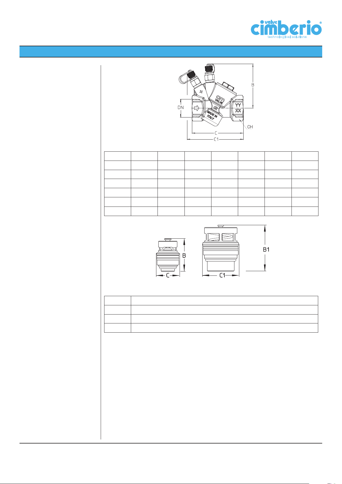
Main dimensions:
Cim 790
technological solutions
DN 15 20 25 25L 32 40 50
Grms. 505 520 600 600 1500 1565 1670
B 74 74 74 93 93 93 93
C 78 78 85 123 123 123 132
C1 89 89 93 125 125 125 130
D 11.5 12.5 14.5 14.5 16.8 16.8 21.1
CH 25 31 38 38 46 52 64
CA1150÷CA2109 CA3073÷CA4262
B 40
C 28
B1 64
C1 48
Cav. Uff. Giacomo Cimberio S.p.A.
10
Page 11
TECHNICAL DATA SHEET
Maintenance:
technological solutions
As a rule, the balancing valve does not need any maintenance. In case of replacement or
need of disassembling of some components of the valve, make sure that the installation is
not under service or pressure.
When flushing the installation, follow these instructions:
• unscrew the plug (6);
• take off the cartridge (2) from the valve body (1) using a common grab acting on the pin
placed at the end of the cartridge;
• close the valve with the plug (6) and let flow the water to flush the installation;
• remove the plug (6), insert the cartridge (2) and then reassemble the plug (6).
If flow rate has to be changed, proceed as above by replacing the installed cartridge with
the one corresponding to the required flow rate. The features of different types of cartridge
are available in the prevoius tables.
7
2
6
8
4
3
5
1
Cav. Uff. Giacomo Cimberio S.p.A.
11
Page 12

®
28017 San Maurizio d’Opaglio (NO) - Italy - Via Torchio, 57 - C.P. 106
Tel. +39 0322 923001 - Fax: +39 0322 967216 / 967755
skype: cimberiosk1, cimberiosk2
www.cimberio.com
© Copyright - Cav. Uff. GIACOMO CIMBERIO S.p.A. - All rights reserved. Tutti i diritti riservati.
IMR 562637 FM 01820 SA 551551 EMS 551553 OHS 551552 ENMS 577357
 Loading...