

Page 1
Fig
TECHNICAL INFORMATION
Pressure independent control balancing valves
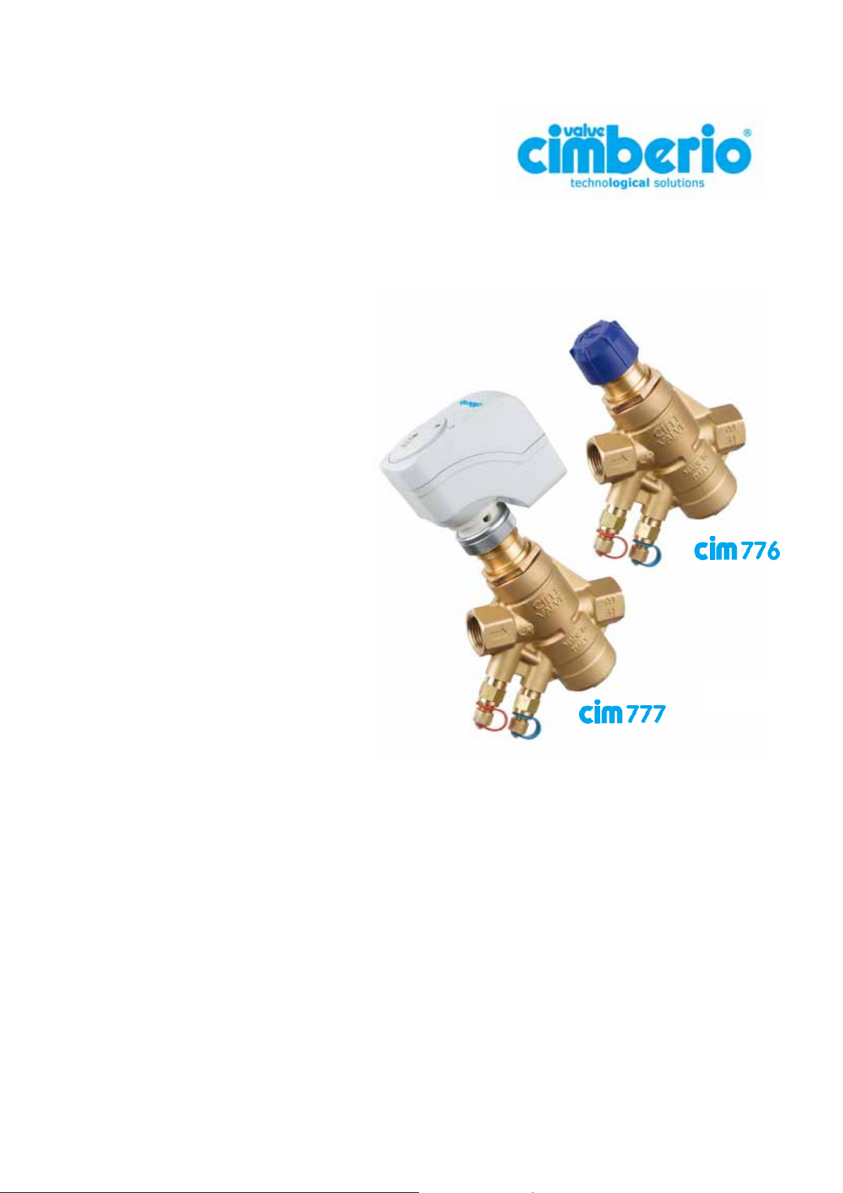
CIM 776 and CIM 777
Description
Balancing valves Cim 776 and Cim 777 are
designed for automatic balancing of heating
and cooling installations, regardless
pressure fluctuations under service, which
might occur due to flow rate changes in the
installation.
Thanks to their unique design, these valves
are able to perform the following functions:
• REGULATION: selection of required
flow rate within the operating range.
• CONTROL: constant flow rate
independent of pressure fluctuations.
• MODULATION: “Full authority” flow
rate modulation for temperature control
(Cim 777 series).
Automatic balancing valves Cim 776 and Cim 777 are made of “CR – Corrosion Resistant” brass according
to ISO 228 standard and are suitable for working pressure up to 25 bar, within the temperature range from
0°C up to +120°C.
Cim 776 e Cim 777 ranges are available with two pressure levels:
1
• “Low Flow”: from 78 l/h up to 1722 l/h;
• “High Flow”: from 244 l/h up to 8586 l/h.
Pagina 1 di 16
Technical leaflet Cim 776 & Cim 777
Revisione 0
Emissione 03/2011
Page 2

They are available in sizes from DN15 up to DN50 (up to DN25 for “Low Flow” version only) and work
properly within a differential pressure operating range between minimum values as specified in “Graphs and
Tables” section of this brochure, and the maximum value of 400 KPa.
The main features of balancing valves Cim 776 and Cim 777 are the following:
• Easy required flow rate selection using presetting dial.
• Automatic balancing in the event of fluctuating pressure conditions in system branches.
• Flow rate modulation along the whole electric actuator stroke.
• Flexibility if the system is modified after the first installation.
• Reduction of balancing costs, improved energy saving and high environmental comfort.
• Easy flushing procedure thanks to quick and simple removal of differential pressure control cartridge
placed inside valve body.
• Reduced installation dimensions thanks to compact valve construction, which does not require inlet and
outlet straight pipelines to stabilize the flow.
Installation procedure
Before installation of CIM 776 and Cim 777, check that inside the valve and the pipes there are no foreign
matters which might damage the tightness of the valve.
Burr pipe connections after having threaded them and distribute the sealing material on pipe threads only
and not on valve threads.
Make sure that required flow rate is within operating range of the valve. Valves may be installed either on
horizontal or vertical pipelines with the electric actuator faced-up and following the arrow direction casted on
the valve body, which shall be the same as the flow one.
For assembly purposes, use a spanner, not a pipe wrench, by applying necessary working torque only on
the valve end nearest the pipe. This helps get a firmer grip and avoids potential damages to valve body.
Make sure that pipe threading length is not longer than valve threads.
The valve is supplied with a cap allowing (when screwed) the manual opening of the valve.
After DPC cartridge removal and manual full opening of the valve, it is possible to flush the system branch
where the valve is installed; when flushing process is over, reposition the DPC control cartridge.
Pagina 2 di 16
Technical leaflet Cim 776 & Cim 777
Revisione 0
Emissione 03/2011
Page 3
Balancing process
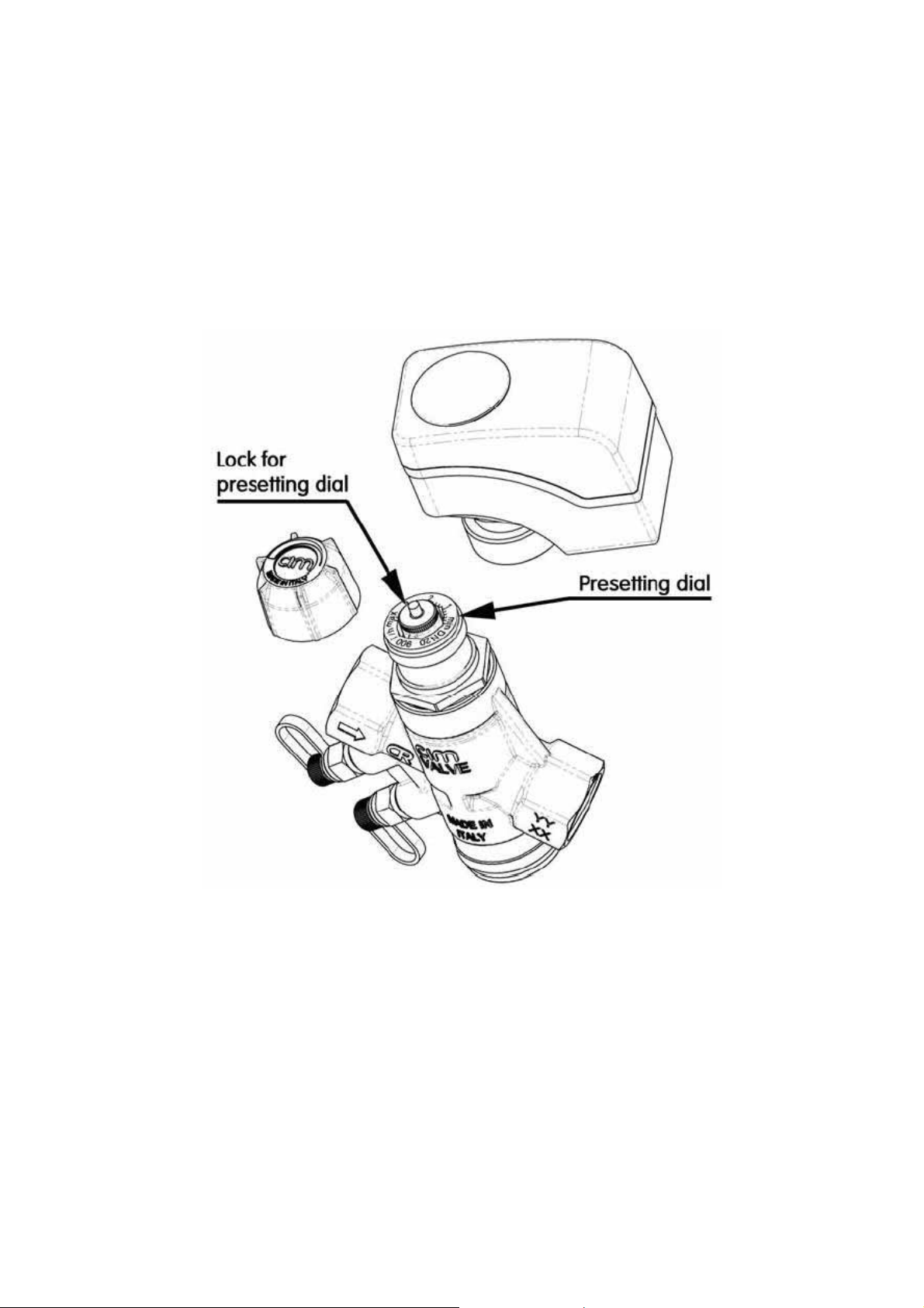
Take the plastic cap screwed on the upper part of the valve off. Turn the presetting dial device (see picture 2)
and match the black mark on the swivel part with the value stated on the fixed part of said device (min., 1, 2,
3, max), which shall correspond to required flow rate.
The relation between flow rate and values shown on the presetting dial device are given by the tables stated
on following pages of this brochure (see “Graphs and Tables”).
Picture 2
Using the differential manometer Cim 726, check that the differential pressure is higher or the same as the
minimum value reported in said tables. The differential manometer interfaces with the balancing valve
through two sensors placed in the binder points of the valve.
When balancing is achieved, screw the lock for presetting dial completely, preventing any unintentional
rotation.
Screw the plastic cap completely to open the valve and achieve the required flow rate (Cim 776) or,
alternatively, assemble the electric actuator for modulating purposes (Cim 777).
Pagina 3 di 16
Technical leaflet Cim 776 & Cim 777
Revisione 0
Emissione 03/2011
Page 4
Maintenance
As a rule, the balancing valve does not need any maintenance. In case of replacement or need of
disassembling of some components of the valve, f.i. for flushing the cartridge of differential pressure, make
sure that the installation is not under service or pressure.
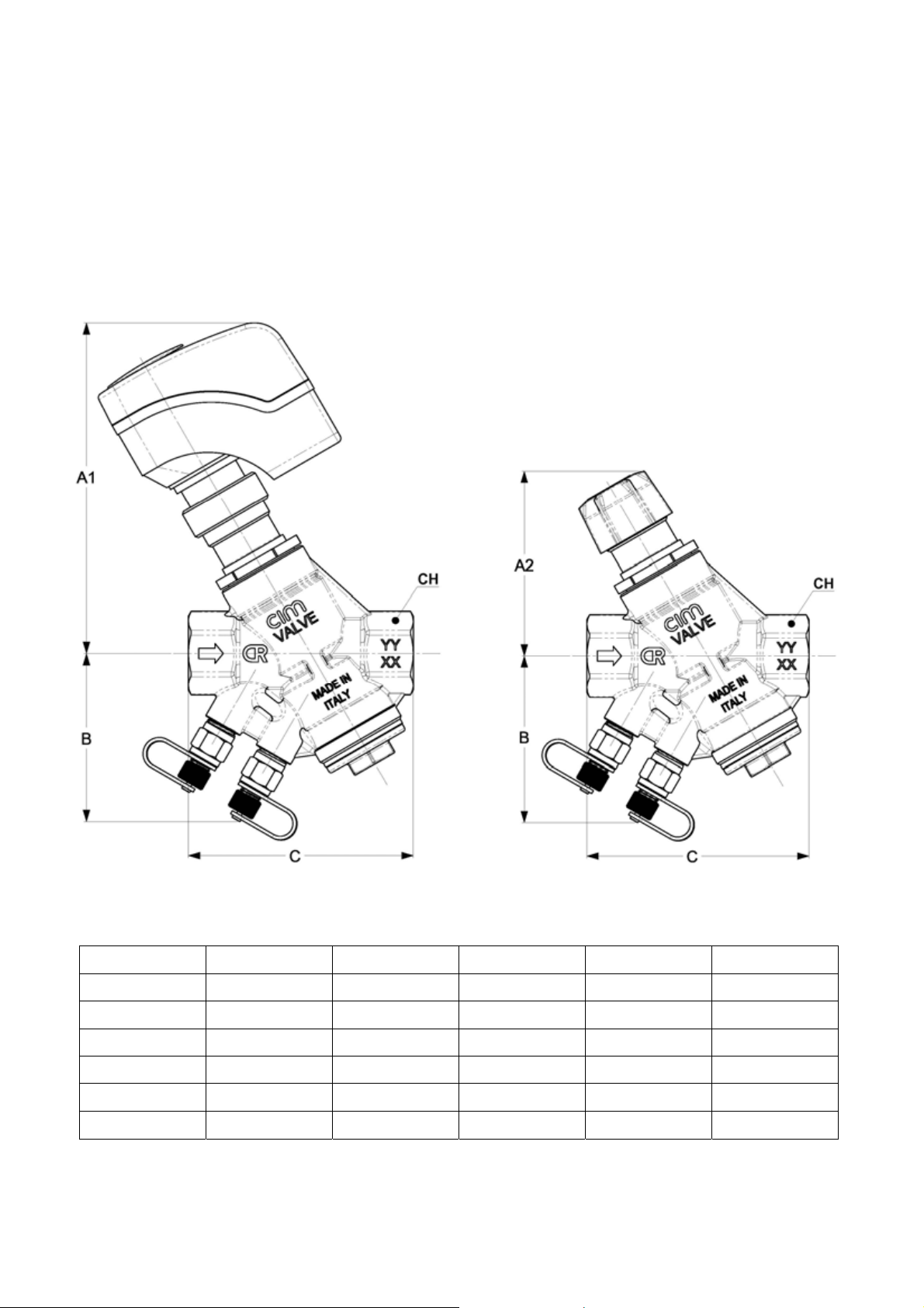
The following table shows the dimensions of the full range of valves Cim 777 and Cim 776.
Picture 3
DN A1 A2 B C CH
1/2”
3/4”
138 81 72 95,5 27
138 81 72 96,5 32
1”
1”1/4
1”1/2
2”
138 81 72 102,5 39
144 87 76 128 49
219 120 87 144 54
225 130 93 155 68
Pagina 4 di 16
Technical leaflet Cim 776 & Cim 777
Revisione 0
Emissione 03/2011
Page 5
Operation principles
Regulation
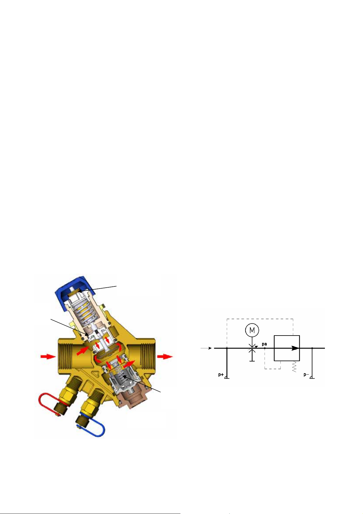
When electric actuator or plastic cap is missing, the valve is normally closed by a swing. On the contrary, if
plastic cap is screwed or electric actuator installed therein, they win the force of the swing and open the
valve (see picture 4). The inlet water goes through a modulating control component whose geometry can be
modified by turning the presetting dial, according to the required flow rate in the system branch where the
valve is installed.
Control
Two different pressures operate on the DPC cartridge. The first one is transmitted through the passage
connecting the valve inlet to the lower section of “p+” cartridge (see hydraulic scheme picture 5); the second
one is registered at valve outlet by the flow rate selecting device “pa”. In order to keep constant the
difference between the mentioned pressures, the DPC cartridge obturator operates by closing the water
outlet bore to reach the preset flow rate, regardless of fluctuating pressure conditions of the system.
Modulation
Calibrated
The electrical actuator performs the modulating function changing the section of flow passage. When
continuous modulation is carried out, the temperature is kept under control. Cim 777 keeps the same
obturator stroke, regardless of the presetting dial position. With continuous modulation, control is excellent
even with small flow opening. This eliminate on/off effect.
Presetting
dial
flow
DPC
cartridge
Picture 4
Picture 5
Pagina 5 di 16
Technical leaflet Cim 776 & Cim 777
Revisione 0
Emissione 03/2011
Page 6
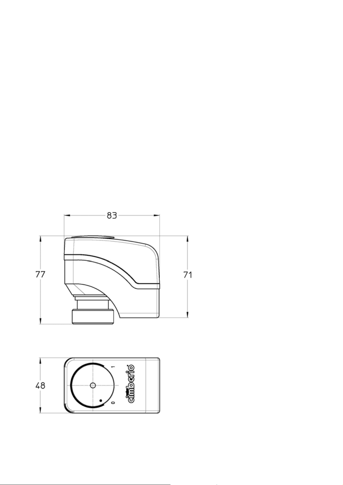
Electric actuators for Cim 777 DN15÷DN32
Three types of electric actuator are available, as follows:
• Cim EMV210/145: 24VAC - proportional;
• Cim EMV210/146: 24VAC – 3 positions;
• Cim EMV210/147: 230VAC – 3 positions.
Their main features are the following:
• Maximum stroke: 5,5 mm;
• 3 positions or 0..10Vdc control signal;
• Swivel nut easy assembling;
• Manual operation by 3mm hexagonal key;
• Short circuit resistance;
• Protection against polarity reversal.
Picture 6
Voltage: 230VAC; 24VAC;
Frequency: 50/60 Hz;
Manual operation: 3 mm hexagonal key;
Cable length : 1,5 metres;
Protection Class: IP 40 according to EN
60529;
Ambient operating conditions: 1°C ÷
50°C; warehousing -5°C ÷ 50°C;
Weight: 350 grms.;
Actuating force: 250 N;
Input impedance: › 100 k Ohm (DC 0-10v);
Actuating time: 150s for 3 positions
version; 75s for proportional 0-10V version.
Pagina 6 di 16
Technical leaflet Cim 776 & Cim 777
Revisione 0
Emissione 03/2011
Page 7
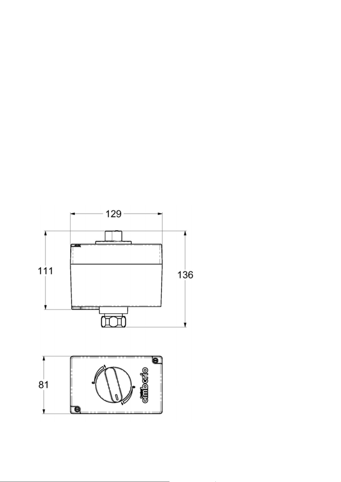
Electric actuator for Cim 777 DN40÷DN50
Three types of electric actuator are available, as follows:
• Cim EMV210/148: 24VAC - proportional;
• Cim EMV210/149: 24VAC – 3 positions;
• Cim EMV210/150: 230VAC – 3 positions.
Their main features are the following :
• Maximum stroke : 6,5 mm;
• 3 positions or 0..10Vdc control signal;
• Swivel nut easy assembling;
• Manual operation by a regulating knob.
Voltage: 230VAC; 24VAC;
Frequency: 50 Hz;
Manual operation: regulating knob;
Cable length: wireless;
Protection Class: IP 54 according EN
60529;
Ambient operating conditions: -5°C ÷
50°C; warehousing -5°C ÷ 50°C;
Weight: 450 grms.;
Actuating force: 400 N;
Input impedance: › 100 k Ohm (DC 0-
10v);
Actuating time: 170s for 3 positions
version; 43s for 0-10V proportional version.
Picture 7
Pagina 7 di 16
Technical leaflet Cim 776 & Cim 777
Revisione 0
Emissione 03/2011
Page 8
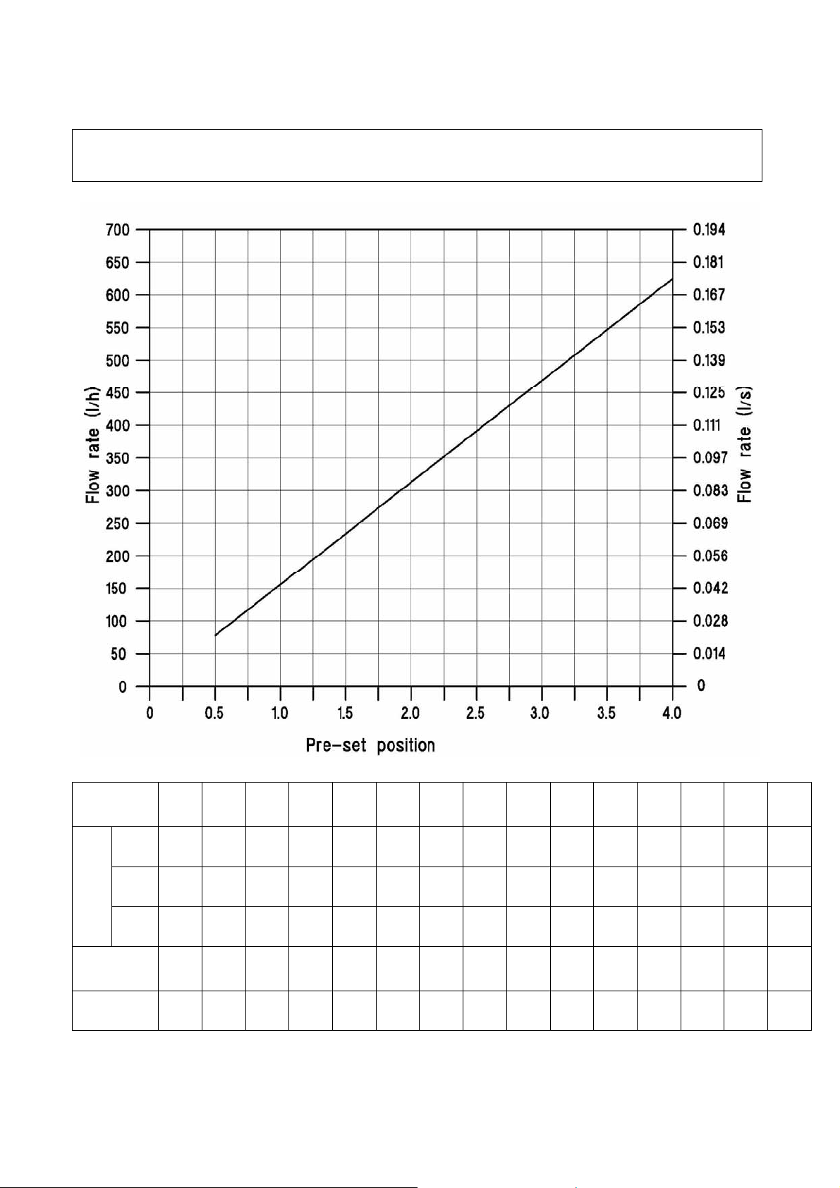
Graphs and Tables
CIM 776 – CIM 777 LOW FLOW 1/2” DN 15
Flow rate according presetting dial device position
Pre-set
position
FLOW RATE
gpm*
Min. ∆p
(KPa)
Kvs
0,50 0,75 1,00 1,25 1,50 1,75 2,00 2,25 2,50 2,75 3,00 3,25 3,50 3,75 4,00
l/h
l/s
78 117 156 195 234 274 313 352 391 430 469 508 547 586 625
0,022 0,033 0,043 0,054 0,065 0,076 0,087 0,098 0,109 0,119 0,130 0,141 0,152 0,163 0,174
0,34 0,52 0,69 0,86 1,03 1,20 1,38 1,55 1,72 1,89 2,06 2,24 2,41 2,58 2,75
14,5 14,5 14,5 15,1 15,1 15,1 15,1 15,7 15,7 15,7 15,7 16,0 16,0 16,0 16,0
0,21 0,31 0,41 0,50 0,60 0,70 0,81 0,89 0,99 1,08 1,18 1,27 1,37 1,47 1,57
* The “gpm” values are corresponding to US gallon per minute.
Pagina 8 di 16
Technical leaflet Cim 776 & Cim 777
Revisione 0
Emissione 03/2011
Page 9
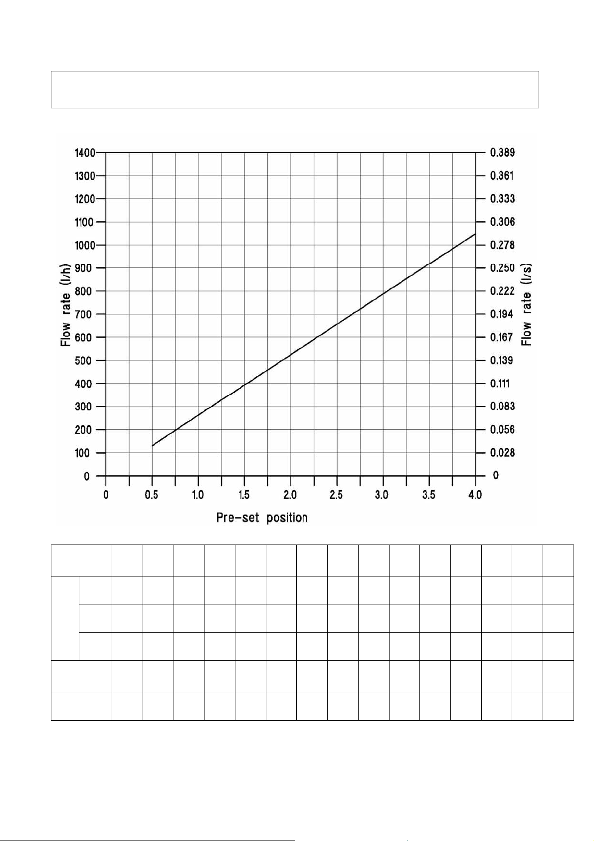
CIM 776 – CIM 777 LOW FLOW 3/4” DN 20
Flow rate according presetting dial device position
Pre-set
position
FLOW RATE
gpm*
Min. ∆p
(KPa)
Kvs
0,50 0,75 1,00 1,25 1,50 1,75 2,00 2,25 2,50 2,75 3,00 3,25 3,50 3,75 4,00
l/h
l/s
131 197 263 328 394 459 525 591 656 722 788 853 919 984 1050
0,036 0,055 0,073 0,091 0,109 0,128 0,146 0,164 0,182 0,201 0,219 0,237 0,255 0,273 0,292
0,58 0,87 1,16 1,44 1,73 2,02 2,31 2,60 2,89 3,18 3,47 3,76 4,04 4,33 4,62
14,5 14,5 14,5 15,1 15,1 15,1 15,1 15,7 15,7 15,7 15,7 16,0 16,0 16,0 16,0
0,34 0,52 0,69 0,84 1,01 1,19 1,35 1,49 1,65 1,83 1,99 2,13 2,30 2,46 2,63
* The “gpm” values are corresponding to US gallon per minute.
Pagina 9 di 16
Technical leaflet Cim 776 & Cim 777
Revisione 0
Emissione 03/2011
Page 10
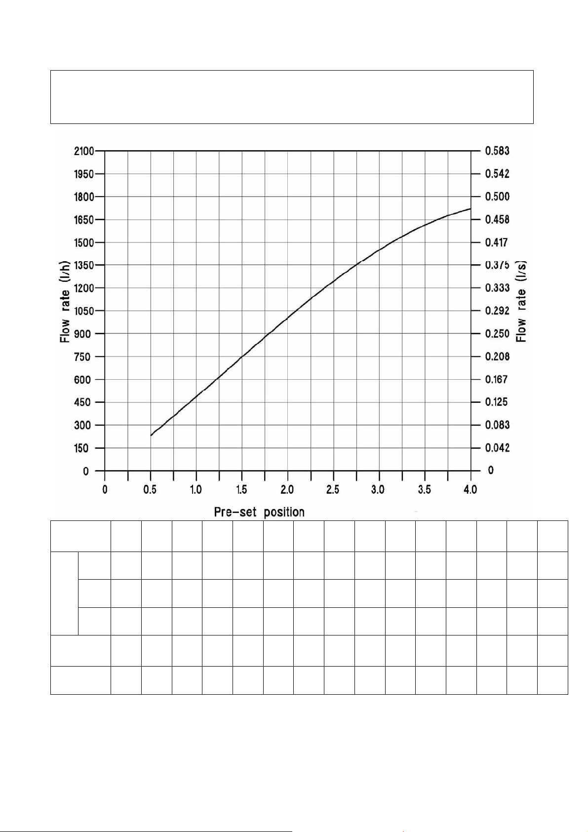
CIM 776 – CIM 777 LOW FLOW 1” DN 25
Flow rate according presetting dial device position
Pre-set
position
FLOW RATE
gpm*
Min. ∆p
(KPa)
Kvs
0,50 0,75 1,00 1,25 1,50 1,75 2,00 2,25 2,50 2,75 3,00 3,25 3,50 3,75 4,00
l/h
l/s
231 357 486 617 749 878 1005 1128 1244 1352 1452 1540 1615 1676 1722
0,064 0,099 0,135 0,171 0,208 0,244 0,279 0,313 0,346 0,376 0,403 0,428 0,449 0,466 0,478
1,02 1,57 2,14 2,72 3,30 3,87 4,43 4,96 5,48 5,95 6,39 6,78 7,11 7,38 7,58
14,0 14,0 14,0 14,8 14,8 14,8 14,8 15,5 15,5 15,5 15,5 16,0 16,0 16,0 16,0
0,62 0,95 1,30 1,60 1,95 2,28 2,61 2,86 3,16 3,44 3,69 3,85 4,04 4,19 4,30
* The “gpm” values are corresponding to US gallon per minute.
Pagina 10 di 16
Technical leaflet Cim 776 & Cim 777
Revisione 0
Emissione 03/2011
Page 11
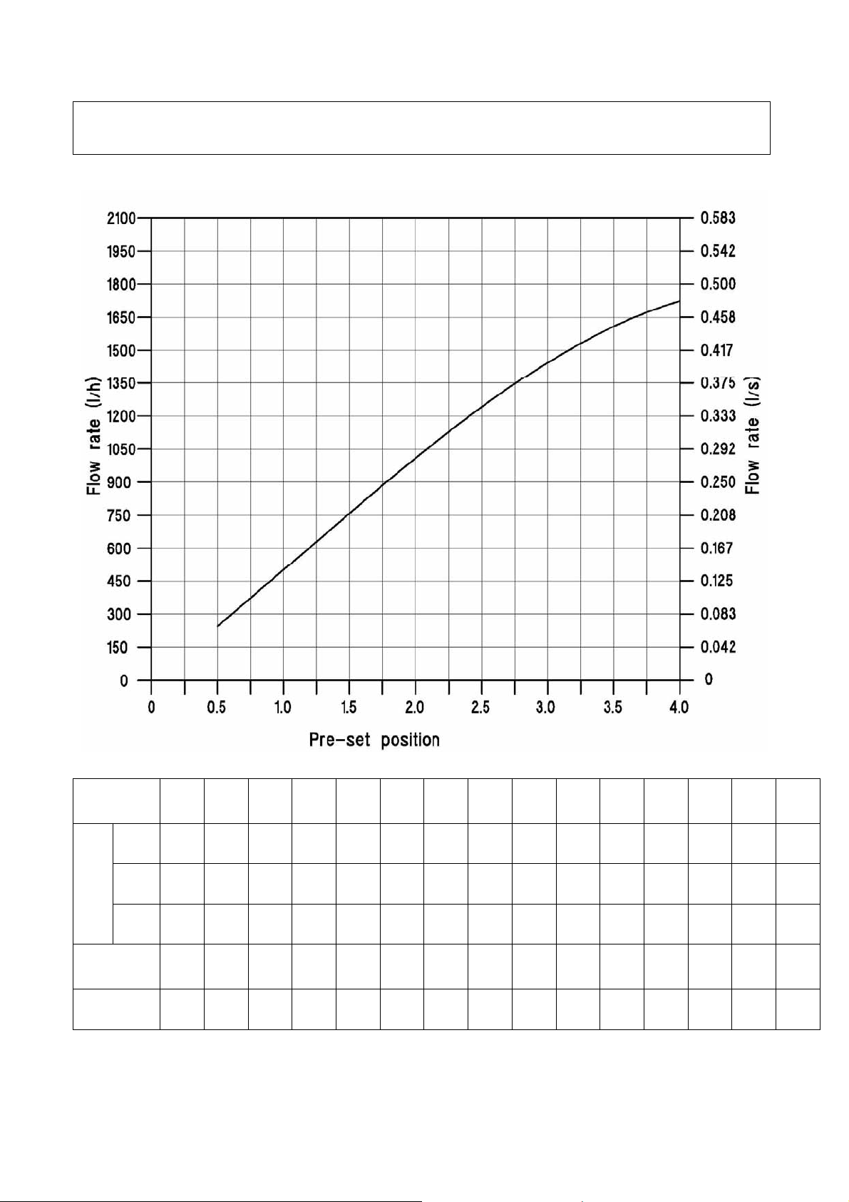
CIM 776 – CIM 777 HIGH FLOW 1/2” DN 15
Flow rate according presetting dial device position
Pre-set
position
FLOW RATE
gpm*
Min. ∆p
(KPa)
Kvs
0,50 0,75 1,00 1,25 1,50 1,75 2,00 2,25 2,50 2,75 3,00 3,25 3,50 3,75 4,00
l/h
l/s
244 372 501 630 759 886 1009 1128 1241 1347 1444 1532 1609 1673 1724
0,068 0,103 0,139 0,175 0,211 0,246 0,280 0,313 0,345 0,374 0,401 0,426 0,447 0,465 0,479
1,08 1,64 2,20 2,77 3,34 3,90 4,44 4,97 5,46 5,93 6,36 6,74 7,08 7,37 7,59
14,0 14,0 14,0 15,8 15,8 15,8 15,8 17,0 17,0 17,0 17,0 18,0 18,0 18,0 18,0
0,65 0,99 1,34 1,58 1,91 2,23 2,54 2,73 3,01 3,27 3,50 3,61 3,79 3,95 4,06
* The “gpm” values are corresponding to US gallon per minute.
Pagina 11 di 16
Technical leaflet Cim 776 & Cim 777
Revisione 0
Emissione 03/2011
Page 12
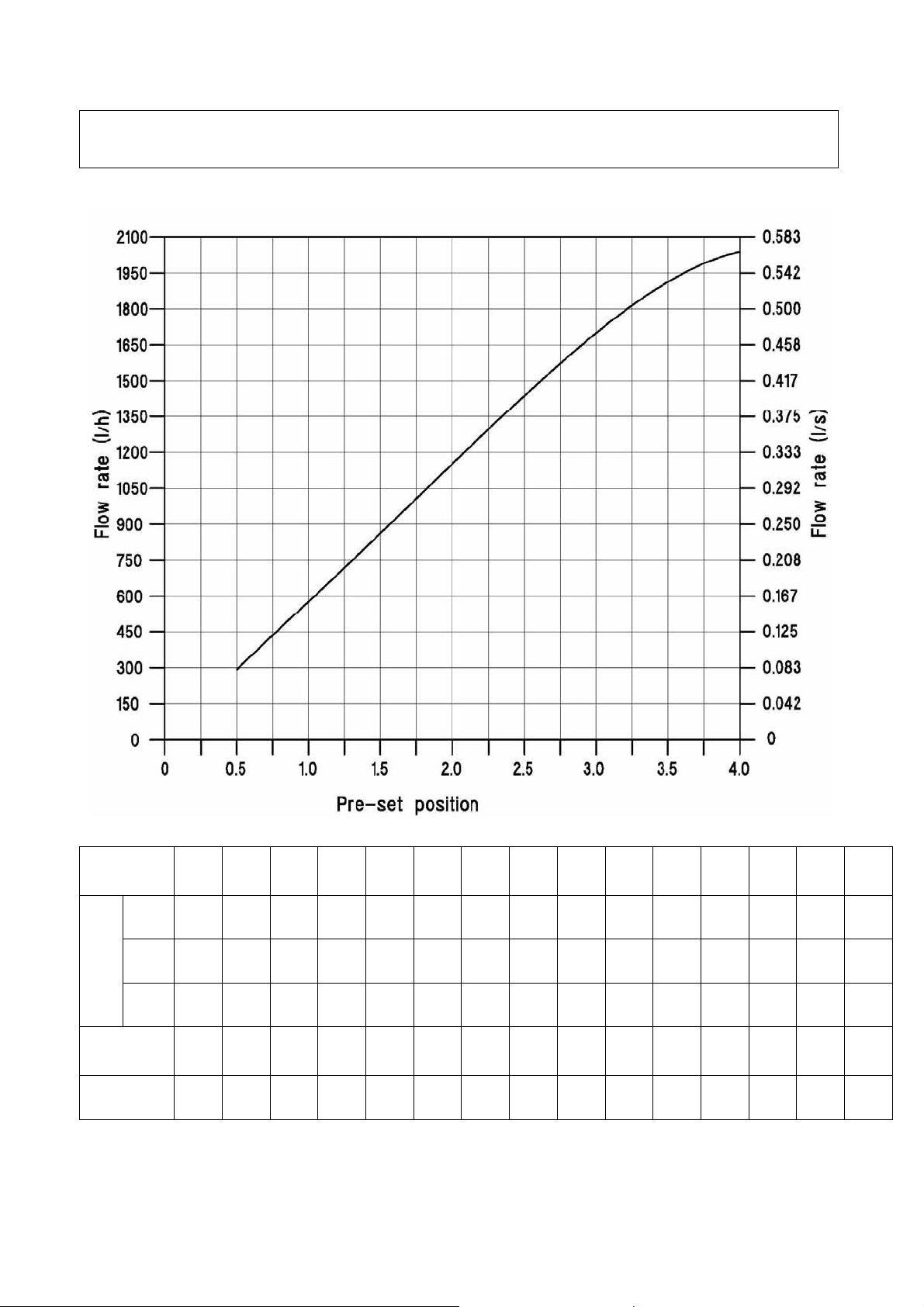
CIM 776 – CIM 777 HIGH FLOW 3/4” DN 20
Flow rate according presetting dial device position
Pre-set
position
FLOW RATE
gpm*
Min. ∆p
(KPa)
Kvs
0,50 0,75 1,00 1,25 1,50 1,75 2,00 2,25 2,50 2,75 3,00 3,25 3,50 3,75 4,00
l/h
l/s
292 435 577 719 863 1007 1152 1296 1437 1573 1700 1815 1913 1990 2039
0,081 0,121 0,160 0,200 0,240 0,280 0,320 0,360 0,399 0,437 0,472 0,504 0,531 0,553 0,566
1,28 1,91 2,54 3,17 3,80 4,43 5,07 5,70 6,33 6,92 7,48 7,99 8,42 8,76 8,98
14,0 14,0 14,0 18,0 18,0 18,0 18,0 20,0 20,0 20,0 20,0 22,0 22,0 22,0 22,0
0,78 1,16 1,54 1,70 2,04 2,38 2,72 2,90 3,21 3,52 3,80 3,87 4,08 4,24 4,34
* The “gpm” values are corresponding to US gallon per minute.
Pagina 12 di 16
Technical leaflet Cim 776 & Cim 777
Revisione 0
Emissione 03/2011
Page 13
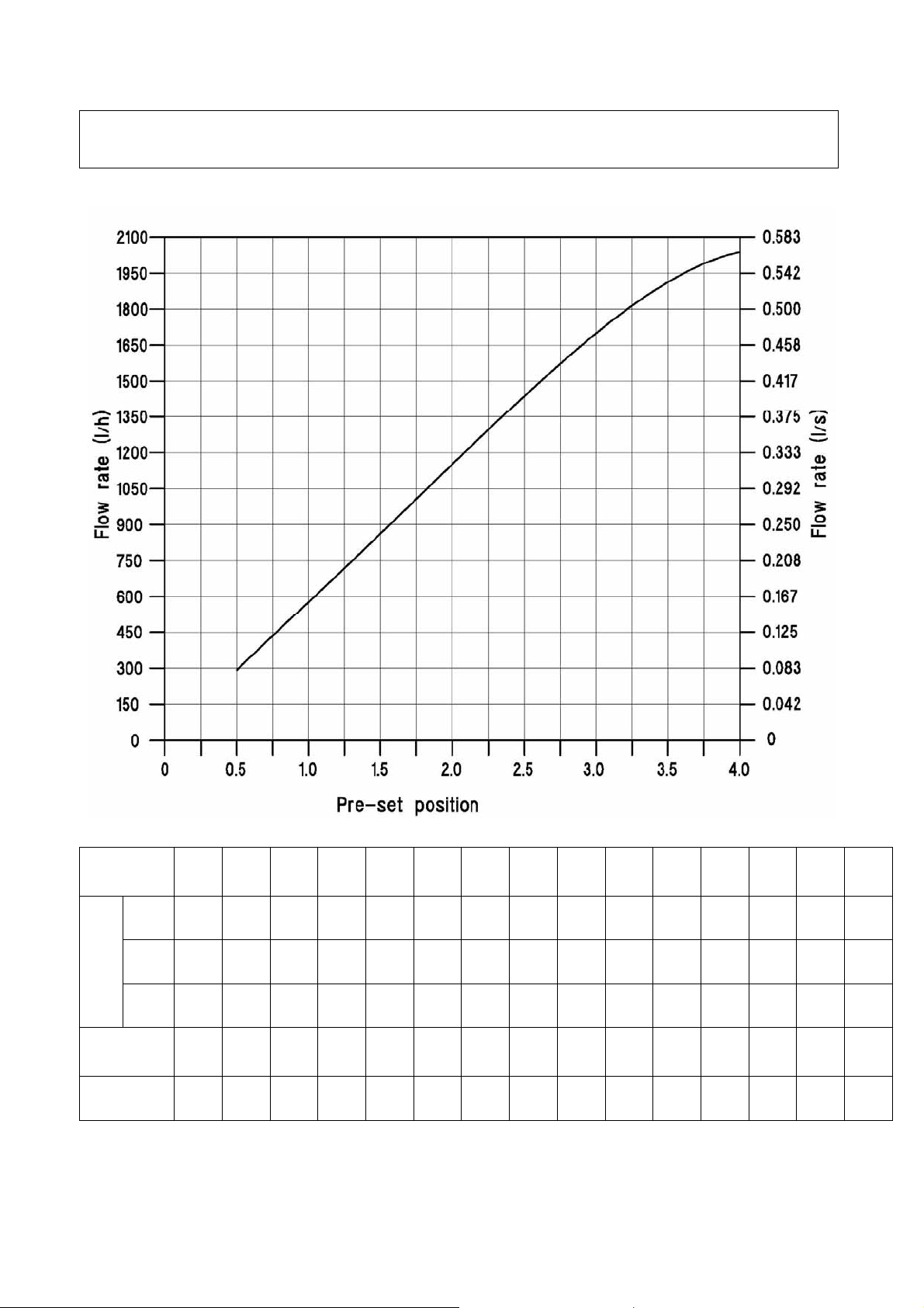
CIM 776 – CIM 777 HIGH FLOW 1” DN 25
Flow rate according presetting dial device position
Pre-set
position
FLOW RATE
gpm*
Min. ∆p
(KPa)
Kvs
0,50 0,75 1,00 1,25 1,50 1,75 2,00 2,25 2,50 2,75 3,00 3,25 3,50 3,75 4,00
l/h
l/s
292 435 577 719 863 1007 1152 1296 1437 1573 1700 1815 1913 1990 2039
0,081 0,121 0,160 0,200 0,240 0,280 0,320 0,360 0,399 0,437 0,472 0,504 0,531 0,553 0,566
1,28 1,91 2,54 3,17 3,80 4,43 5,07 5,70 6,33 6,92 7,48 7,99 8,42 8,76 8,98
14,0 14,0 14,0 18,0 18,0 18,0 18,0 20,0 20,0 20,0 20,0 22,0 22,0 22,0 22,0
0,78 1,16 1,54 1,70 2,04 2,38 2,72 2,90 3,21 3,52 3,80 3,87 4,08 4,24 4,34
* The “gpm” values are corresponding to US gallon per minute.
Pagina 13 di 16
Technical leaflet Cim 776 & Cim 777
Revisione 0
Emissione 03/2011
Page 14
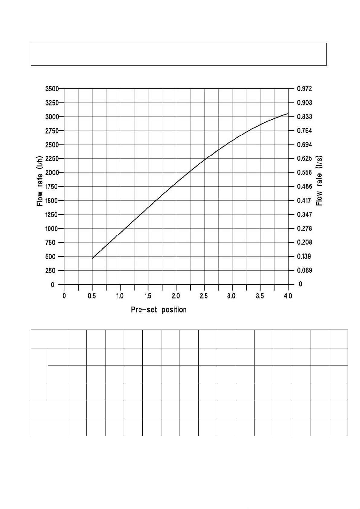
CIM 776 – CIM 777 HIGH FLOW 1”1/4 DN 32
Flow rate according to presetting dial device position
Pre-set
position
FLOW RATE
gpm*
Min. ∆p
(KPa)
Kvs
0,50 0,75 1,00 1,25 1,50 1,75 2,00 2,25 2,50 2,75 3,00 3,25 3,50 3,75 4,00
l/h
l/s
465 692 921 1150 1377 1600 1816 2024 2221 2405 2574 2726 2858 2969 3056
0,129 0,192 0,256 0,319 0,382 0,444 0,504 0,562 0,617 0,668 0,715 0,757 0,794 0,825 0,849
2,05 3,05 4,05 5,06 6,06 7,04 7,99 8,91 9,78 10,59 11,33 12,00 12,58 13,07 13,45
14,5 14,5 14,5 16,0 16,0 16,0 16,0 17,0 17,0 17,0 17,0 18,0 18,0 18,0 18,0
1,22 1,82 2,42 2,87 3,44 4,00 4,54 4,91 5,39 5,83 6,24 6,42 6,74 7,00 7,20
* The “gpm” values are corresponding to US gallon per minute.
Pagina 14 di 16
Technical leaflet Cim 776 & Cim 777
Revisione 0
Emissione 03/2011
Page 15
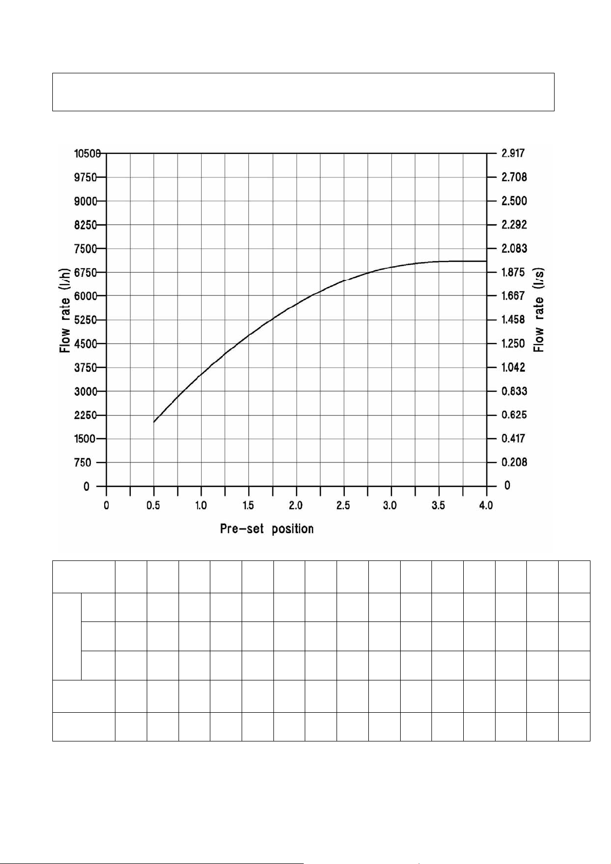
CIM 776 – CIM 777 HIGH FLOW 1”1/2 DN 40
Flow rate according to presetting dial device position
Pre-set
position
FLOW RATE
gpm*
Min. ∆p
(KPa)
Kvs
0,50 0,75 1,00 1,25 1,50 1,75 2,00 2,25 2,50 2,75 3,00 3,25 3,50 3,75 4,00
2022 2825 3538 4179 4758 5279 5741 6139 6470 6729 6916 7033 7090 7105 7105
l/h
0,562 0,785 0,983 1,161 1,322 1,466 1,595 1,705 1,797 1,869 1,921 1,954 1,969 1,974 1,974
l/s
8,90 12,44 15,58 18,40 20,95 23,24 25,27 27,03 28,48 29,62 30,44 30,96 31,21 31,28 31,28
16,0 16,5 16,5 18,0 18,0 20,0 20,0 22,0 22,5 24,0 25,0 26,0 26,0 26,0 26,0
5,06 6,96 8,71 9,85 11,22 11,80 12,84 13,09 13,64 13,73 13,80 13,80 13,90 13,94 13,94
* The “gpm” values are corresponding to US gallon per minute.
Pagina 15 di 16
Technical leaflet Cim 776 & Cim 777
Revisione 0
Emissione 03/2011
Page 16
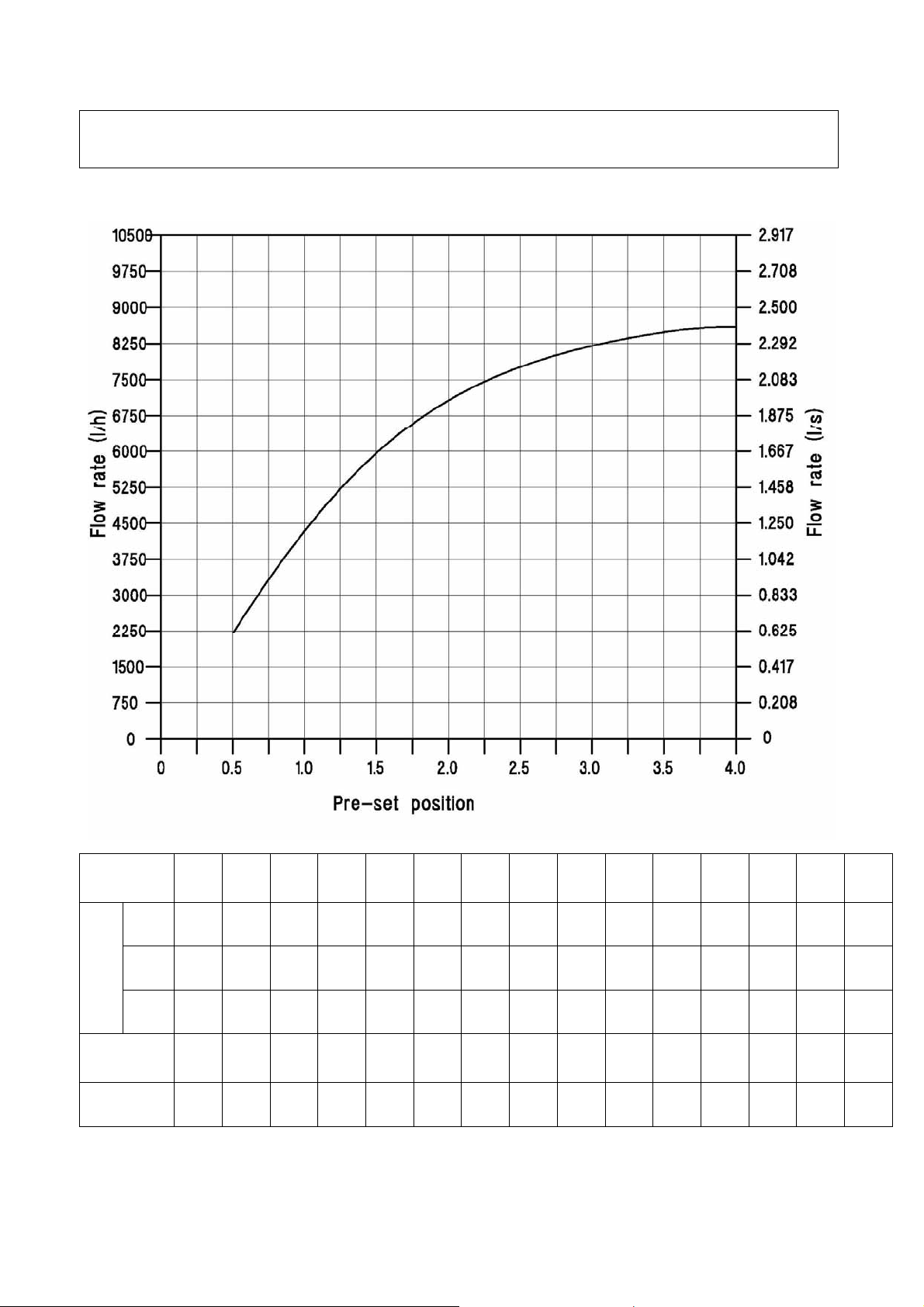
CIM 776 – CIM 777 HIGH FLOW 2” DN 50
Flow rate according to presetting dial device position
Pre-set
position
FLOW RATE
gpm*
Min. ∆p
(KPa)
Kvs
0,50 0,75 1,00 1,25 1,50 1,75 2,00 2,25 2,50 2,75 3,00 3,25 3,50 3,75 4,00
2204 3325 4337 5218 5963 6577 7070 7459 7766 8009 8204 8362 8486 8568 8586
l/h
0,612 0,924 1,205 1,449 1,657 1,827 1,964 2,072 2,157 2,225 2,279 2,323 2,357 2,380 2,385
l/s
9,70 14,64 19,09 22,97 26,25 28,95 31,12 32,84 34,19 35,25 36,11 36,81 37,36 37,72 37,80
19,0 22,0 22,0 25,0 25,0 28,0 28,0 29,0 29,0 30,0 30,0 31,0 32,0 32,0 32,0
5,05 7,09 9,25 10,43 11,93 12,43 13,36 13,85 14,42 14,62 14,98 15,00 15,00 15,15 15,18
* The “gpm” values are corresponding to US gallon per minute.
Pagina 16 di 16
Technical leaflet Cim 776 & Cim 777
Revisione 0
Emissione 03/2011
 Loading...