

Page 1
Page 2

Contents
Safety Precautions
06
Getting Started
09
Product Overview 09
In the Box
09
Names of Parts
10
Manual Feeding, Single-sided Printing 10
Auto Feeding, Single-sided Printing, 1 Input hopper
14
16
Load Blue Cleaning Roller & Ribbon
22
Load Blue Cleaning Roller 22
Load Ribbon
23
Load Cards
24
Place Cards in the Input Hopper 24
Place Cards after Removing the Input Hopper
25
Magnetic Cards
28
Input Hopper & Ribbon Lock
29
Input Hopper Lock 29
Ribbon Lock
29
Print Single Card
27
Install/Remove Output Stacker
30
Open the Output Stacker Cover and Remove the Cards 30
Auto Feeding, Single-sided Printing, 2 Input hoppers
Auto Feeding, Double-sided Printing, 1 Input hopper 18
20
Auto Feeding, Double-sided Printing, 2 Input hoppers
Manual Feeding, Double-sided Printing 12
Page 3

System Requirements 33
Install Program
33
① Supported Operating System
33
② Recommended Specifications
33
Install Software 33
① Install Software Using Local Port (USB)
33
② Install Software for Network Printer
35
③ Configure Networking Settings
40
④ Install Software from the List of Connected Devices (Optional)
47
1)Network Configuration Window
40
2) DHCP (Dynamic Host Configuration Protocol)?
41
3)Network Settings - Automatic (DHCP supported)
41
4)Network Settings - Manual
44
Uninstall Program
49
Print Cards
49
Set as Default Printer 49
Change Printer Port (Using the Printer Driver)
50
Select Input Hopper in the Printer Settings
52
Select Input Hopper 1/2 from External Program
54
Print Using Application Programs 55
Print Using Application Programs & Configure Driver Settings
55
Configure Printer Default Settings in Application Programs 55
① Layout
56
② Output
57
③ Output-Option
58
④ Image
59
⑤ Magnetic
60
Connect Power & Communication Cables
32
Use the Spring Load to Remove a Small Quantity of Cards 31
Remove the Output Stacker and the Cards
31
(Windows Preview)
Page 4

Check IP Address 62
① If Connected to a PC
64
② If Not Connected to a PC: User Mode
65
Print Self-Test Card 64
Maintenance Instructions
67
Supported Cards 67
① Size
67
② Thickness
67
③ Acceptable Cards
67
④ Unacceptable Cards
67
Clean the Printer
67
Clean the Exterior 67
Clean Inside the Printer Using Cleaning Kit
68
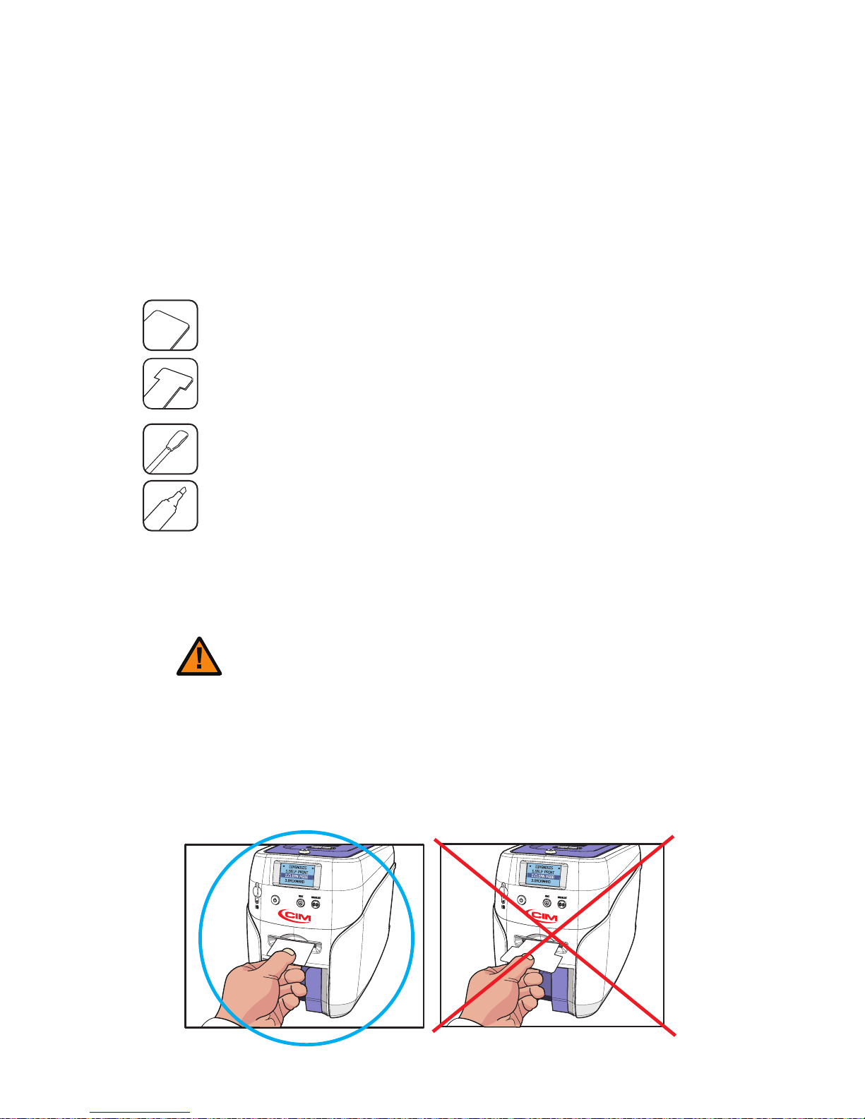
① Cleaning Kit & Use
68
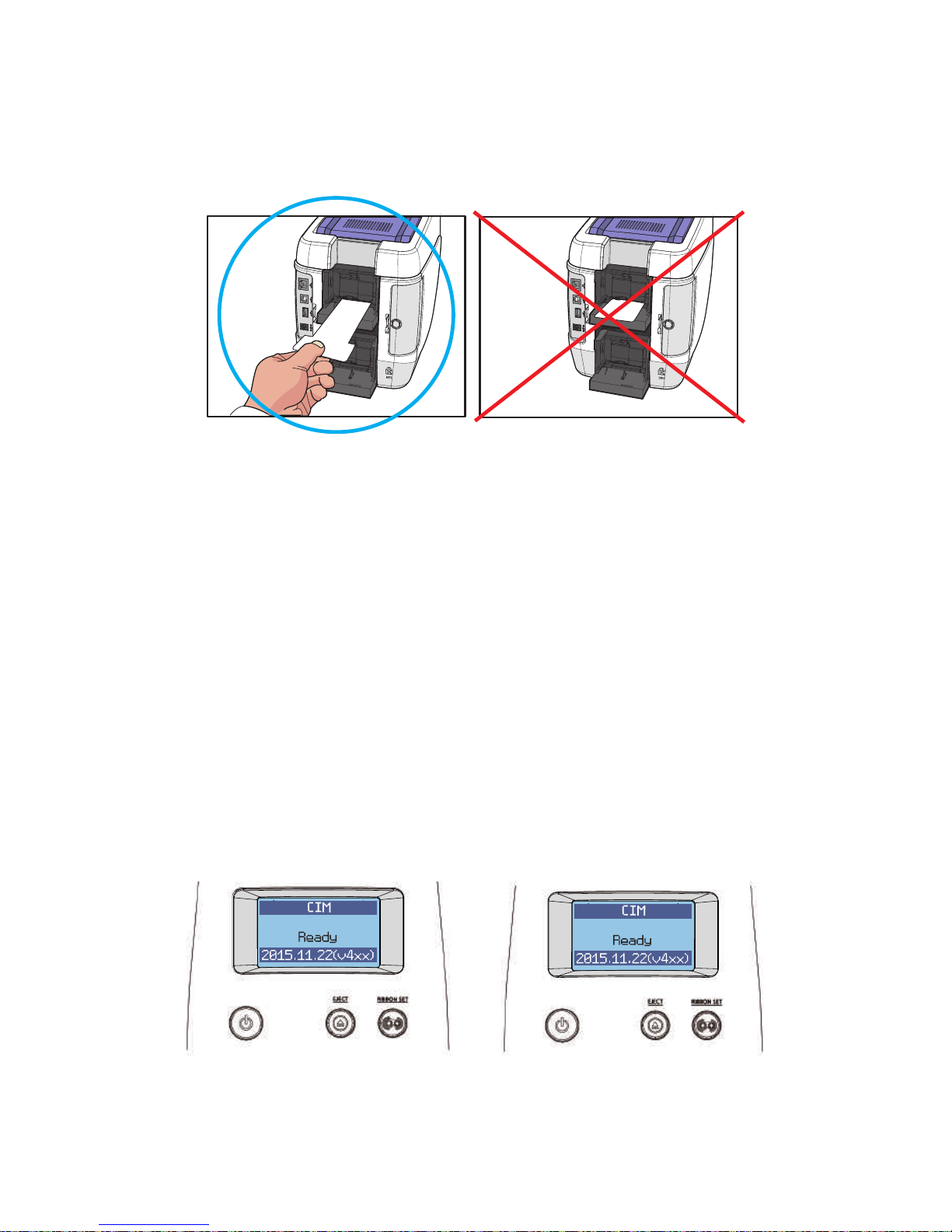
② Clean the Printer Using CR80 Cleaning Card / Long-T Cleaning Card
68
1) Check the Proper Use of CR80 Cleaning Card / Long-T Cleaning Card
68
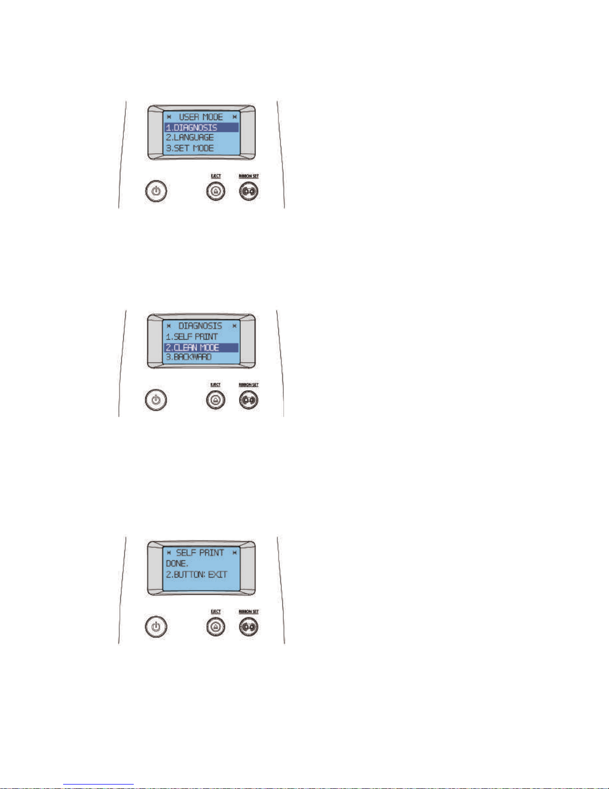
2) Not Connected to a PC: User Mode
69
3) Connected to a PC
72
③ Clean the Printer Using Alcohol Swab
73
1) Clean the Inside of the Printer Using Alcohol Swab
73
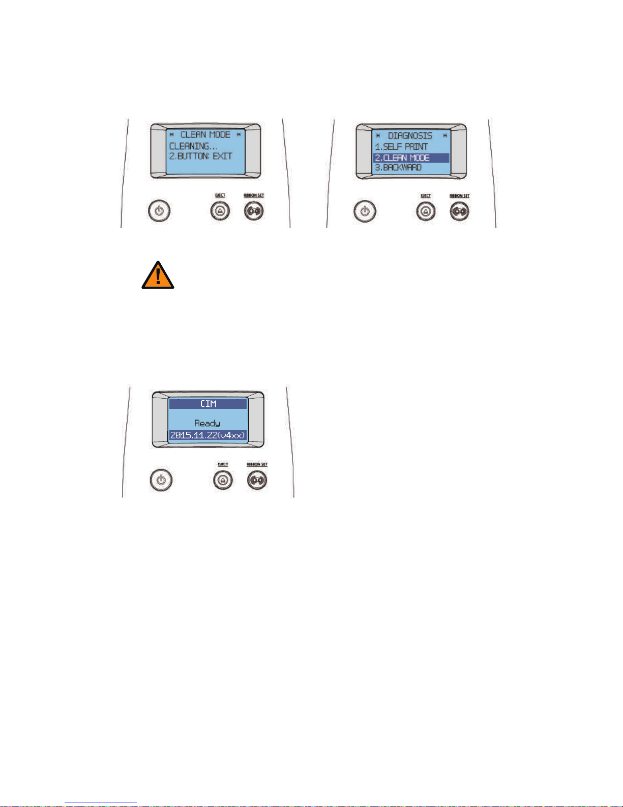
2) Clean the Printer's TPH Using Alcohol Swab
74
Clean the Blue Cleaning Roller 75
Troubleshooting
75
Errors 75
① TPH
75
② Card Feeding
78
1) Remove Jammed Card (Single-sided Printing)
78
③ Ribbon
81
④ Card
81
1) Replace the TPH
76
Check IP Address & Print Test Card
62
⑥ Control
61
⑦ About
62
2) Remove Jammed Card (Double-sided Printing)
79
Page 5

④ Miscellaneous
83
Additional Errors 83
Ribbon Specifications
83
Color Ribbons 83
Monochrome Ribbons
83
Printer Specifications
84
Product Features 84
Standard Specifications
84
① Printing Type
84
② Printing Function
84
③ Resolution
84
④ Printing Speed
84
1) Color Printing
84
2) Monochrome Printing
84
⑤ Card Capacity
85
Optional Accessories 85
Printer Specifications
85
① Dimensions (Width x Length x Height) & Weight
85
1) Manual Feed
85
2) Auto Feed
85
② Power Adapter
85
③ Font
85
⑤ Interface
86
⑥ PC Specifications
86
⑦ Software
86
④ Memory
86
② Ribbon
82
③ SAM
82
① Card
82
Warranty Certificate
86
Warning 82
⑤ Miscellaneous
81
Page 6
Safety Precautions
Before using this product, please make sure that you have read the safety precautions
described below. The safety precautions noted on this page are categorized as Warning,
Caution, Attention,and Note. We are not responsible for any injuries or damage when
the product is not used in compliance with these precautions.
Note
This is a note that provides more details or information that is
useful for users.
Important
Use this information to check and inspect for the proper operation of
the product.
Caution
Not following this caution can cause service interruption or product
damage.
Warning
These warnings must always be followed; otherwise, this may result
in serious injury or damage.
06
Install printer and ready
Page 7

-Warning
These warnings must always be followed; otherwise, serious injury
may result.
- Do not use a damaged plug or loose outlet.
- Do not pull the cable to unplug or touch the plug with wet hands.
- Do not bend the cable by force or place any heavy objects on it.
- Keep it unplugged if not in use for an extended period of time or in
case of lightning or thunder.
Power
Installation
/ Storage
- Do not install the printer in a place where it may be subjected to
moisture, dust, or splashes of water (rain).
- Keep the printer away from heat sources, as well as lit candles and
cigarettes.
- Unplug the printer when moving it.
(If the printer is moved while plugged, the cable may be damaged
and cause electric shock.)
- Keep any inflammable liquid, gas, and aerosol away from the printer.
Cleaning
- Keep the power plug clean, away from dust and water.
- Unplug when cleaning, and do not spray water or use benzene or
thinner.
Misc.
- Do not place metal objects, chemicals, or anything with water on it.
- If you observe strange smoke, odor, or noise from the printer, unplug it
immediately and contact your dealer.
- Use only the specified adapter.
※ Do not use adapters from other devices, e.g. laptop, monitor, game
console.
07
CIM User Guide Manual
Page 8

Installation/
Storage
Misc.
- Do not remove any cover or protective device that is attached with
screws.
- Do not operate the printer while your hand is placed inside.
- Clean and maintain the printer according to the user instructions.
- Do not disassemble, repair, or modify the printer arbitrarily.
-Caution
Not following this caution can cause service interruption or product
damage.
- Do not install the printer on an unstable surface.
- Do not place the printer under direct sunlight as it may cause a
malfunction.
08
Install printer and ready
Page 9
Thank you for purchasing the
This printer is designed to print cards quickly and easily according to your specifications.
It supports IC and RF cards as well as magnetic cards and can print high quality color
images on the surface of the card using the dye-sublimation method.
In addition, the user can edit and print various types of barcodes, magnetic cards, and
photos using software provided together.
This printer is suitable for printing membership cards, rewards cards, employee ID
cards, and access cards as it prints directly to PVC cards for faster and more efficient
printing.
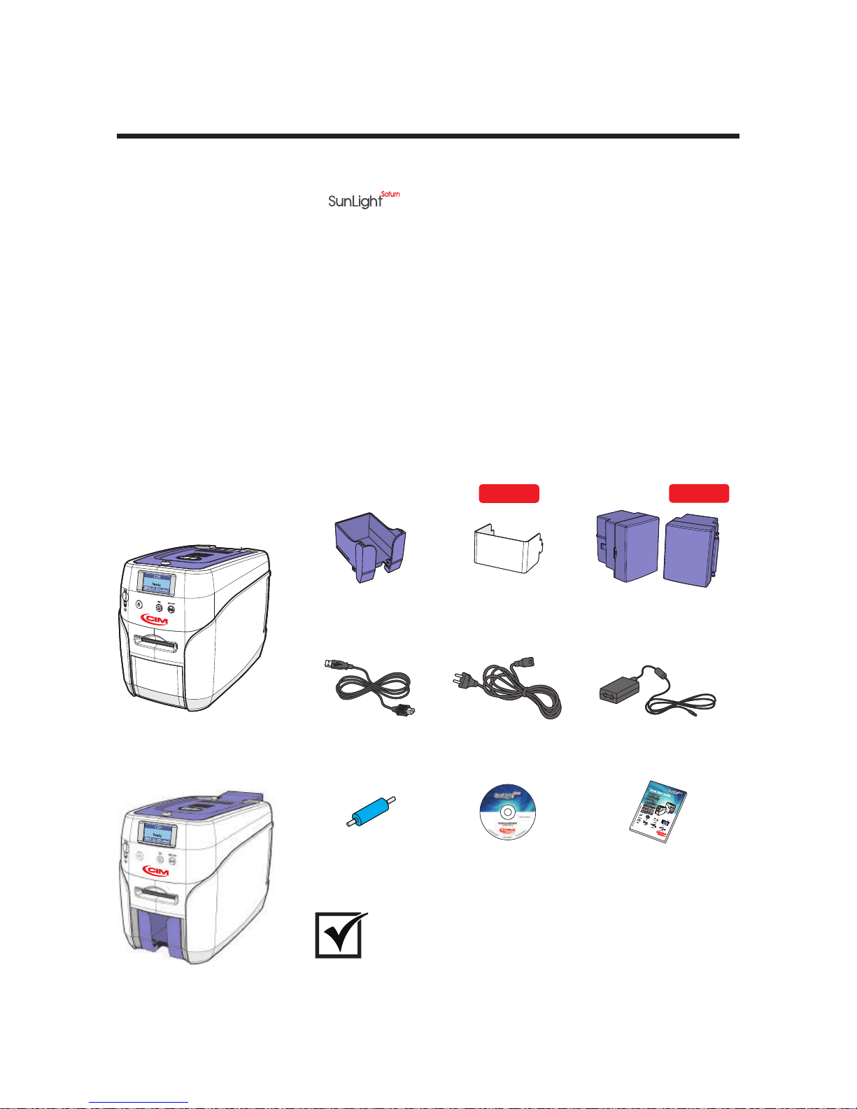
-In the Box
Cleaning Roller
Power Cable Power AdaptorUSB Cable
Installation CD
Quick Start Guide
Output Stacker Input Hopper Lock Input Hopper
Manual Card Printing
Auto feeding Card Printing
Getting Started
Please make sure that all the components and accessories are included in
the box. If there are missing or damaged items, then please contact your
dealer for assistance.
Important
OPTION
OPTION
-Product Overview
09
CIM User Guide Manual
Page 10
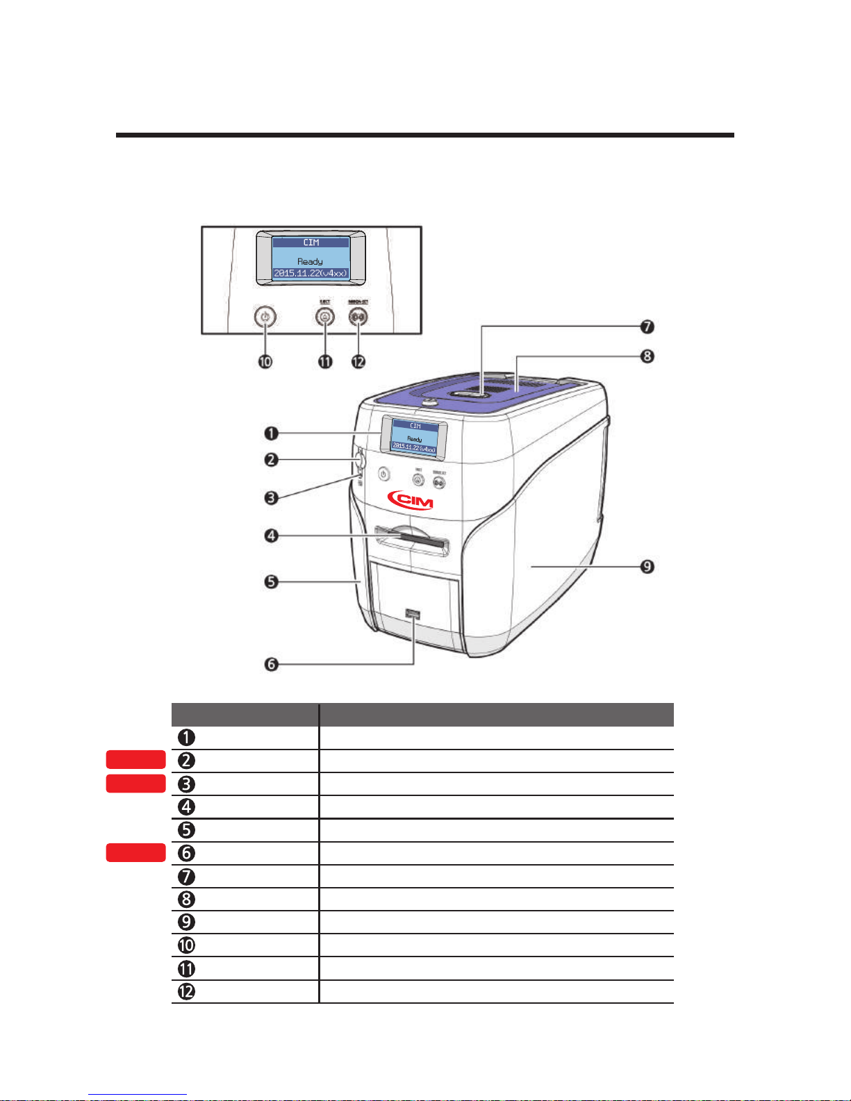
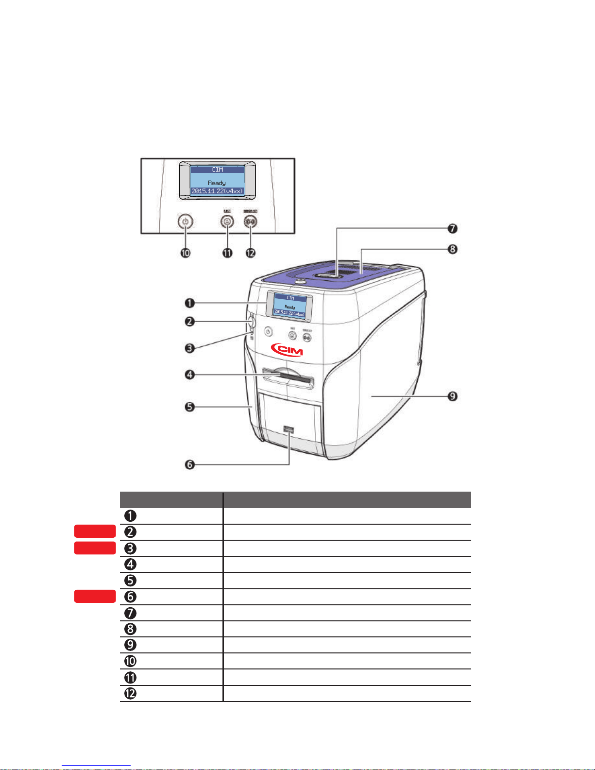
LCD Display Displays the printer’s operation status on the LCD screen.
Mobile Connector Used for inserting mobile chips.
Mobile Connector LED
Indicates the mobile chip status.
Single Card Slot Used to insert or release a single card.
Left Side Cover Open to install optional accessories or fix errors.
USB Socket Used to insert USB memory media or to connect to a PC.
Top Cover Button Opens the Top Cover.
Top Cover Open to replace the cleaning roller.
Right Side Cover Open to replace the main board or fix errors.
Power Switch
Turns the printer on/off.
Card Eject Button Release the card inside the printer.
Names of Parts
Manual Feeding, Single-sided Printing
OPTION
OPTION
OPTION
10
Ribbon Set Button Replace or reposition the ribbon.
Name Description
Install printer and ready
Page 11
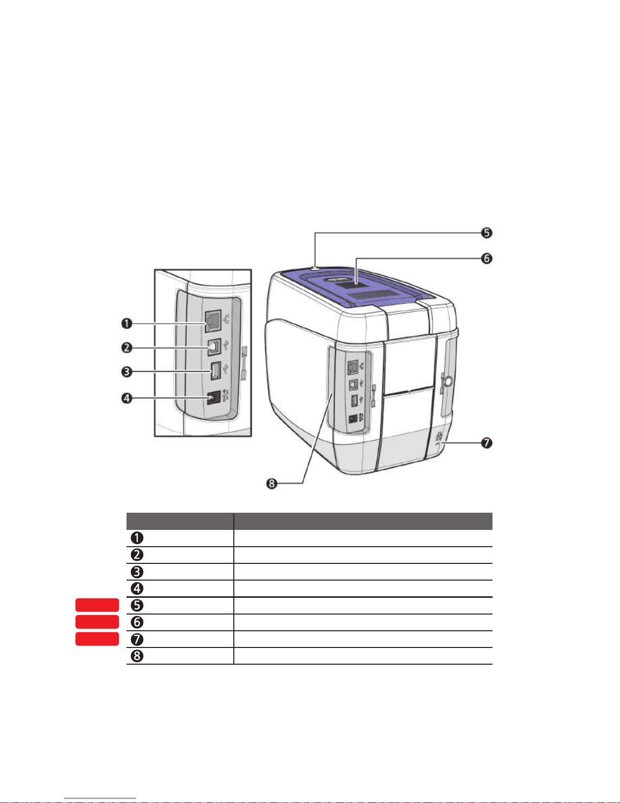
Ethernet Port Used to connect to a network using a LAN cable.
USB Port Used to connect to a PC using a USB cable.
USB Socket Used to insert USB memory media or to connect to a PC.
Power Supply Port Connects to the power supply.
Top Cover Lock Key Locks/unlocks the Top Cover.
External RF Recognizes an RF card.
Printer Lock Use this to mount a security lock.
Side Cover Open Section
Press to open the Side Cover.
OPTION
OPTION
OPTION
11
Name Description
CIM User Guide Manual
Page 12
Manual Feeding, Double-sided Printing
LCD Display Displays the printer’s operation status on the LCD screen.
Mobile Connector Used for inserting mobile chips.
Mobile Connector LED
Indicates the mobile chip status.
Single Card Slot Used to insert or release a single card.
Left Side Cover Open to install optional accessories or fix errors.
USB Socket Used to insert USB memory media or to connect to a PC.
Top Cover Button Opens the Top Cover.
Top Cover Open to replace the cleaning roller.
Right Side Cover Open to replace the main board or fix errors.
Power Switch
Turns the printer on/off.
Card Eject Button Release the card inside the printer.
OPTION
OPTION
OPTION
Ribbon Set Button Replace or reposition the ribbon.
Name Description
12
Install printer and ready
Page 13
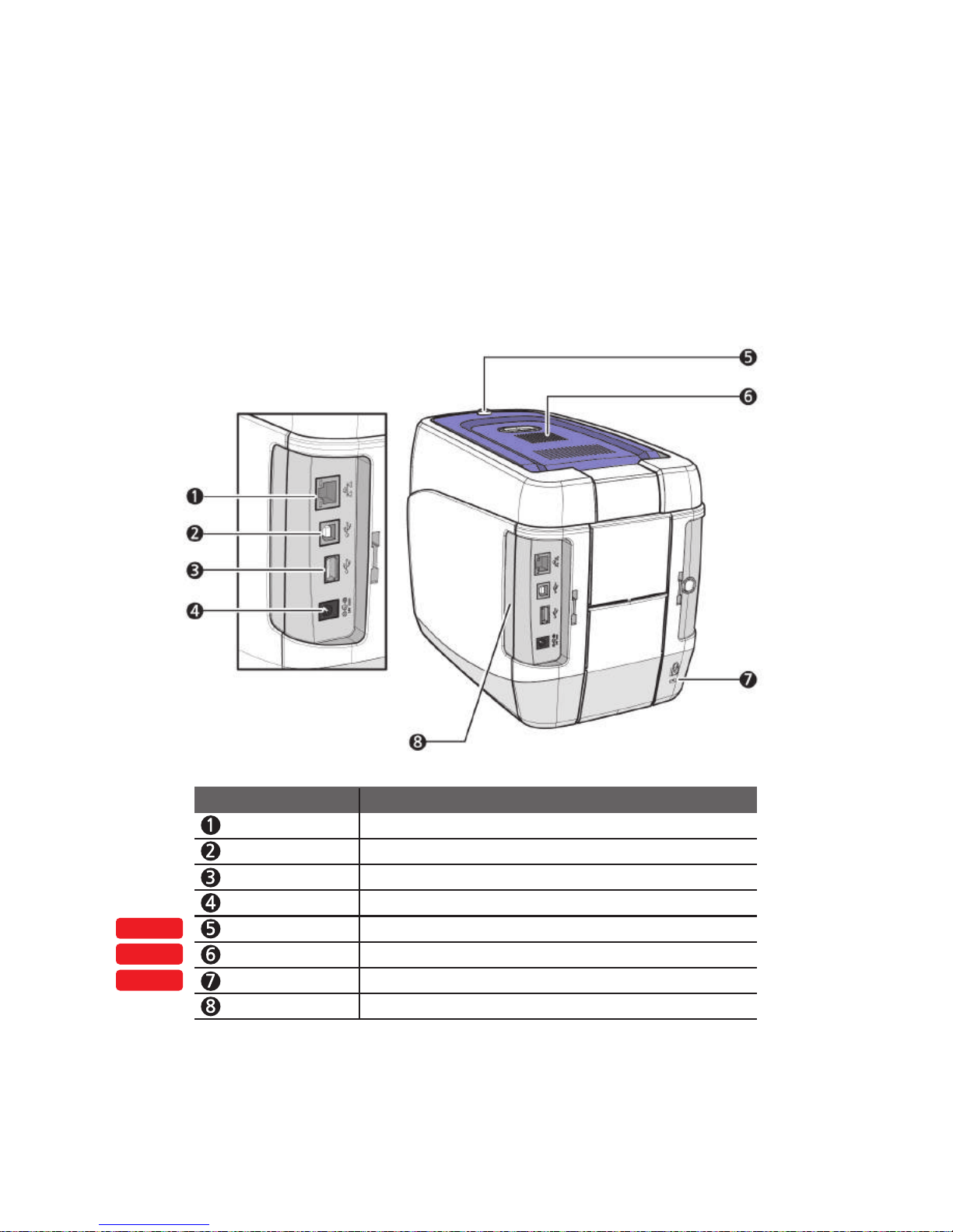
Ethernet Port Used to connect to a network using a LAN cable.
USB Port Used to connect to a PC using a USB cable.
USB Socket Used to insert USB memory media or to connect to a PC.
Power Supply Port Connects to the power supply.
Top Cover Lock Key Locks/unlocks the Top Cover.
External RF Recognizes an RF card.
Printer Lock Use this to mount a security lock.
Side Cover Open Section
Press to open the Side Cover.
OPTION
OPTION
OPTION
Name Description
13
CIM User Guide Manual
Page 14
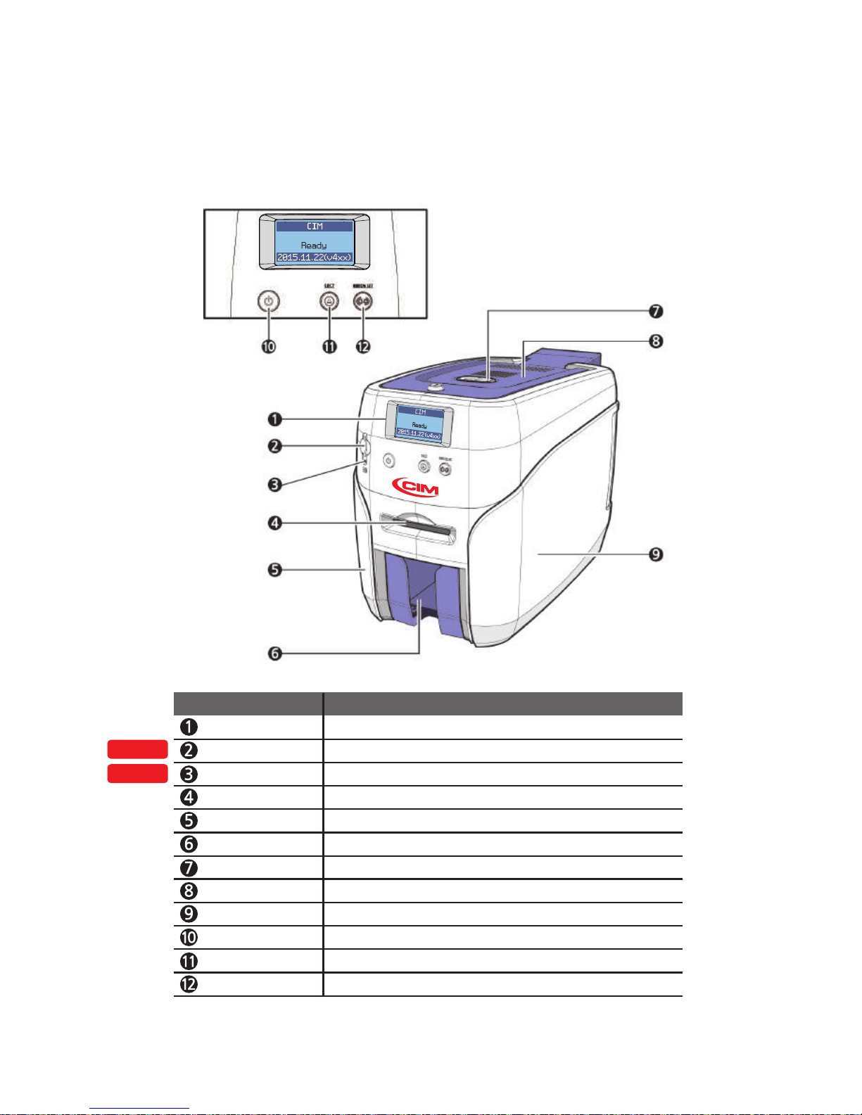
Auto Feeding, Single-sided Printing, 1 Input hopper
OPTION
OPTION
LCD Display Displays the printer’s operation status on the LCD screen.
Mobile Connector Used for inserting mobile chips.
Mobile Connector LED
Indicates the mobile chip status.
Single Card Slot Used to insert or release a single card.
Left Side Cover Open to install optional accessories or fix errors.
Output Stacker Stores printed cards (max. 60 cards).
Top Cover Button Opens the Top Cover.
Top Cover Open to replace the cleaning roller.
Right Side Cover Open to replace the main board or fix errors.
Power Switch
Turns the printer on/off.
Card Eject Button Release the card inside the printer.
Ribbon Set Button Replace or reposition the ribbon.
Name Description
14
Install printer and ready
Page 15
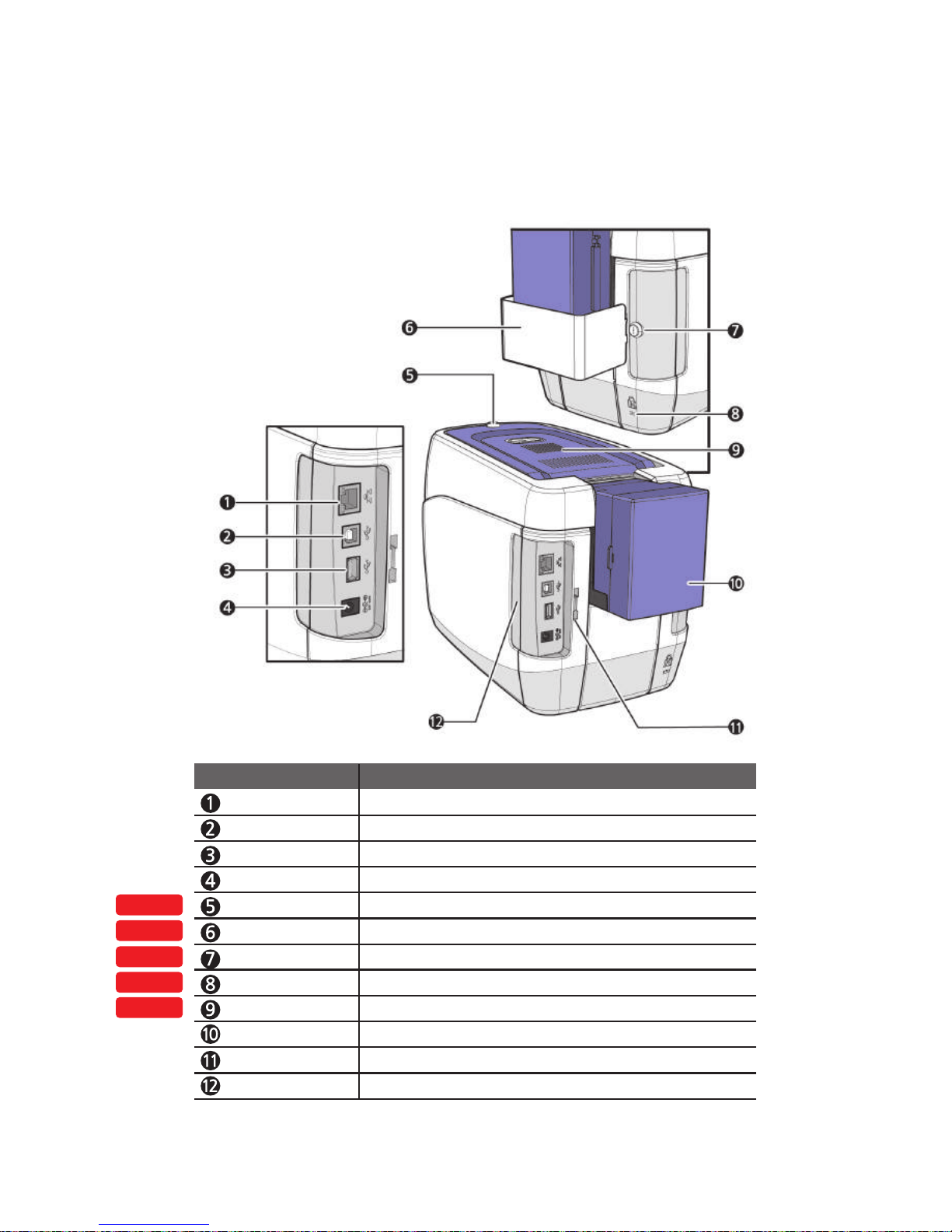
Top Cover Lock Key Locks/unlocks the Top Cover.
External RF Recognizes an RF card.
Printer Lock Use this to mount a security lock.
Side Cover Open Section
Press to open the Side Cover.
Input Hopper (Standard)
Stores cards to print (max. 100 cards).
Locks/unlocks the input hopper.
Lock Connector Link
Used to connect the Back Cover to the Input Hopper Lock.
Input Hopper Lock Used to lock the input hopper for Security.
OPTION
OPTION
OPTION
OPTION
OPTION
Ethernet Port Used to connect to a network using a LAN cable.
USB Port Used to connect to a PC using a USB cable.
USB Socket Used to insert USB memory media or to connect to a PC.
Power Supply Port Connects to the power supply.
Name Description
Input Hopper Lock Key
15
CIM User Guide Manual
Page 16
OPTION
OPTION
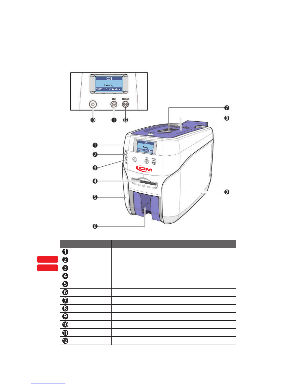
LCD Display Displays the printer’s operation status on the LCD screen.
Mobile Connector Used for inserting mobile chips.
Mobile Connector LED
Indicates the mobile chip status.
Single Card Slot Used to insert or release a single card.
Left Side Cover Open to install optional accessories or fix errors.
Output Stacker Stores printed cards (max. 60 cards).
Top Cover Button Opens the Top Cover.
Top Cover Open to replace the cleaning roller.
Right Side Cover Open to replace the main board or fix errors.
Power Switch
Turns the printer on/off.
Card Eject Button Release the card inside the printer.
Ribbon Set Button Replace or reposition the ribbon.
Name Description
Auto Feeding, Single-sided Printing, 2 Input hoppers
16
Install printer and ready
Page 17
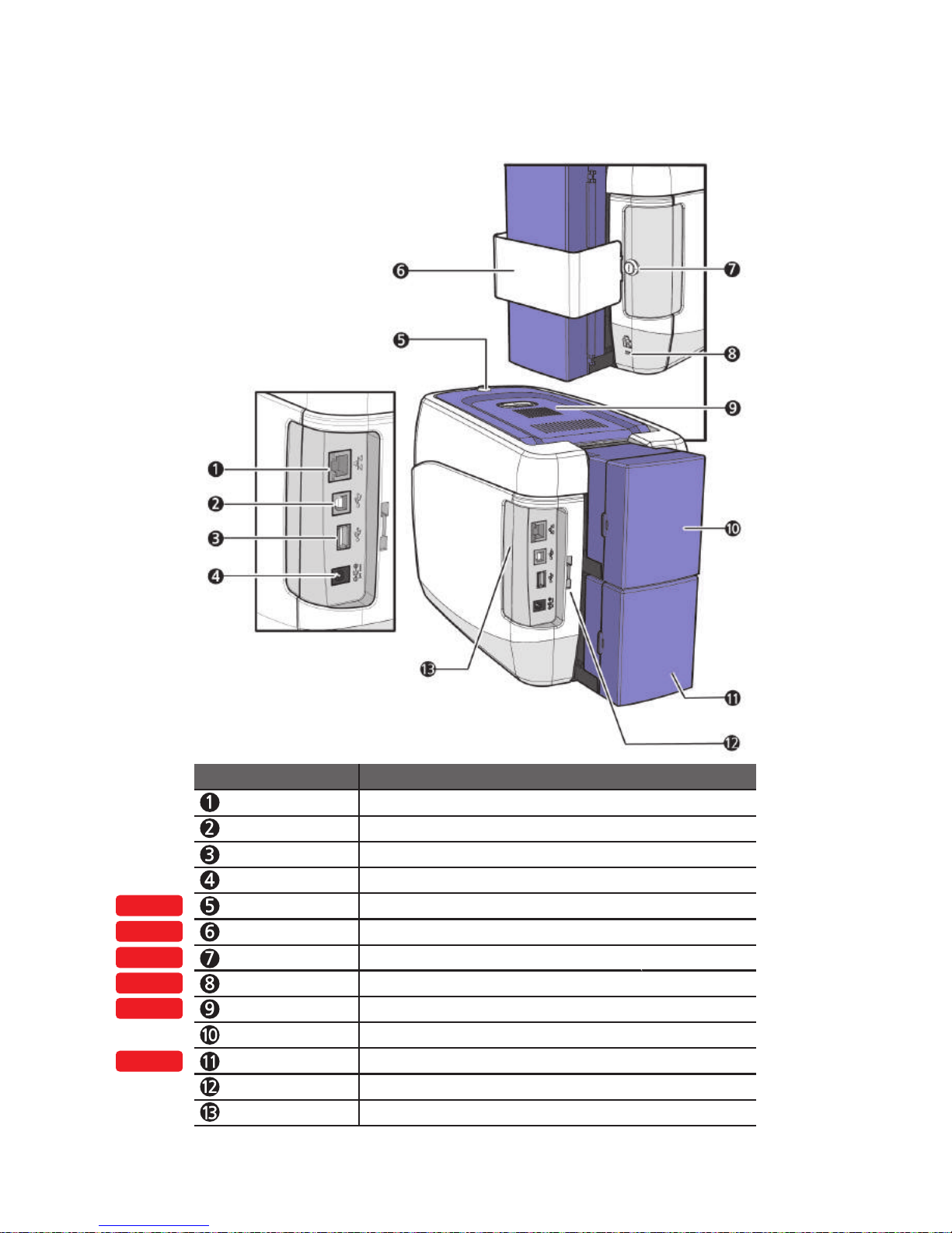
Press to open the Side Cover.
Lock Connector Link
Used to connect the back cover to the Input Hopper Lock.
Input Hopper (Optional)
Stores additional cards (Standard+Optional: max. 200 cards)
OPTION
OPTION
OPTION
OPTION
OPTION
OPTION
Ethernet Port Used to connect to a network using a LAN cable.
USB Port Used to connect to a PC using a USB cable.
USB Socket Used to insert USB memory media or to connect to a PC.
Power Supply Port Connects to the power supply.
Name Description
Top Cover Lock Key Locks/unlocks the Top Cover.
Printer Lock Use this to mount a security lock.
Locks/unlocks the Input Hopper.
Input Hopper Lock Used to lock the Input hopper for security
External RF Recognizes an RF card.
Input Hopper (Standard)
Stores cards to print (max. 100 cards).
Side Cover Open Section
Input Hopper Lock Key
17
CIM User Guide Manual
Page 18
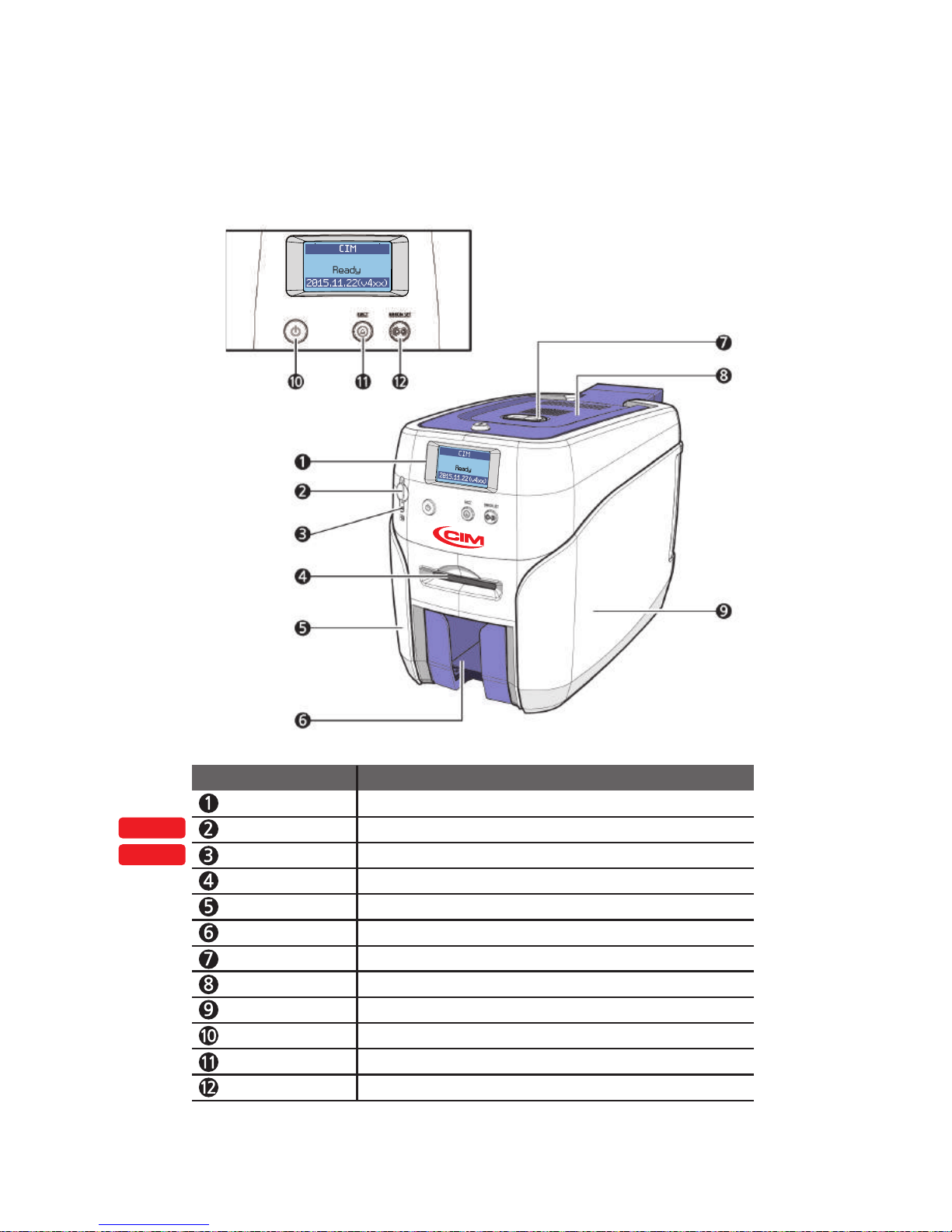
Auto Feeding, Double-sided Printing, 1 Input hopper
OPTION
OPTION
LCD Display Displays the printer’s operation status on the LCD screen.
Mobile Connector Used for inserting mobile chips.
Mobile Connector LED
Indicates the mobile chip status.
Single Card Slot Used to insert or release a single card.
Left Side Cover Open to install optional accessories or fix errors.
Output Stacker Stores printed cards (max. 60 cards).
Top Cover Button Opens the Top Cover.
Top Cover Open to replace the cleaning roller.
Right Side Cover Open to replace the main board or fix errors.
Power Switch
Turns the printer on/off.
Card Eject Button Release the card inside the printer.
Ribbon Set Button Replace or reposition the ribbon.
Name Description
18
Install printer and ready
Page 19
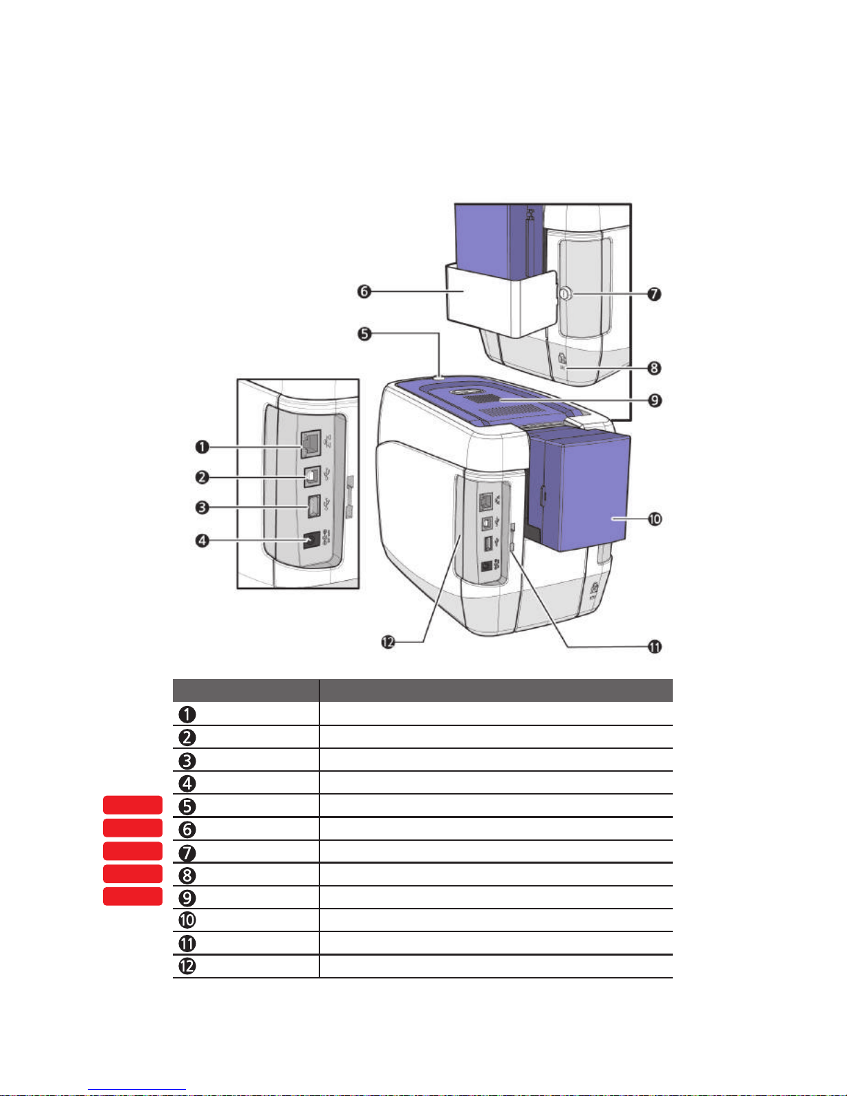
Top Cover Lock Key Locks/unlocks the Top Cover.
External RF Recognizes an RF card.
Printer Lock Use this to mount a security lock.
Side Cover Open Section
Press to open the Side Cover.
Input Hopper (Standard)
Stores cards to print (max. 100 cards).
Locks/unlocks the input hopper.
Lock Connector Link
Used to connect the Back Cover to the Input Hopper Lock.
Input Hopper Lock Used to lock the input hopper for Security.
OPTION
OPTION
OPTION
OPTION
OPTION
Ethernet Port Used to connect to a network using a LAN cable.
USB Port Used to connect to a PC using a USB cable.
USB Socket Used to insert USB memory media or to connect to a PC.
Power Supply Port Connects to the power supply.
Name Description
Input Hopper Lock Key
19
CIM User Guide Manual
Page 20
OPTION
OPTION
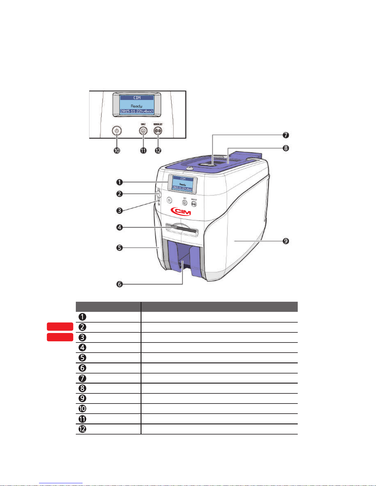
LCD Display Displays the printer’s operation status on the LCD screen.
Mobile Connector Used for inserting mobile chips.
Mobile Connector LED
Indicates the mobile chip status.
Single Card Slot Used to insert or release a single card.
Left Side Cover Open to install optional accessories or fix errors.
Output Stacker Stores printed cards (max. 60 cards).
Top Cover Button Opens the Top Cover.
Top Cover Open to replace the cleaning roller.
Right Side Cover Open to replace the main board or fix errors.
Power Switch
Turns the printer on/off.
Card Eject Button Release the card inside the printer.
Ribbon Set Button Replace or reposition the ribbon.
Name Description
Auto Feeding, Double-sided Printing, 2 Input hoppers
20
Install printer and ready
Page 21
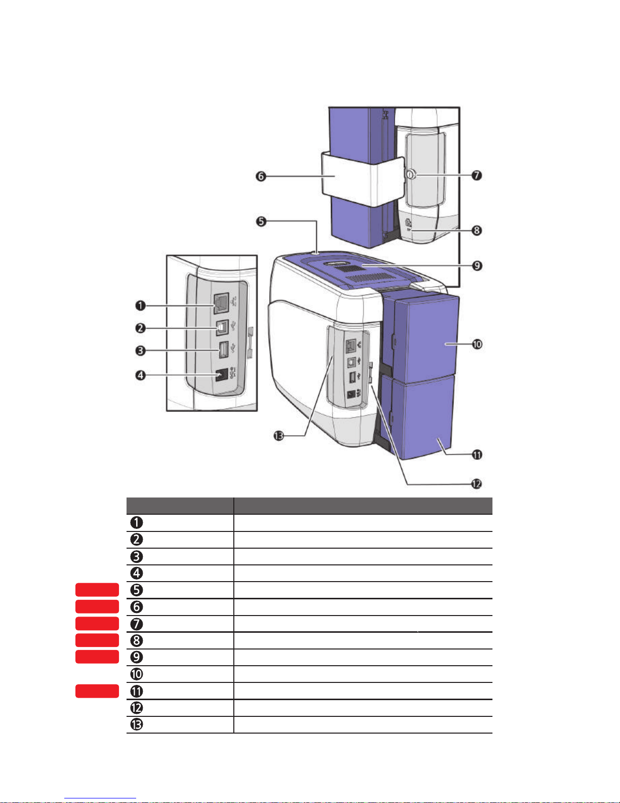
Press to open the Side Cover.
Lock Connector Link
Used to connect the back cover to the Input Hopper Lock.
Input Hopper (Optional)
Stores additional cards (Standard+Optional: max. 200 cards)
OPTION
OPTION
OPTION
OPTION
OPTION
OPTION
Ethernet Port Used to connect to a network using a LAN cable.
USB Port Used to connect to a PC using a USB cable.
USB Socket Used to insert USB memory media or to connect to a PC.
Power Supply Port Connects to the power supply.
Name Description
Top Cover Lock Key Locks/unlocks the Top Cover.
Printer Lock Use this to mount a security lock.
Locks/unlocks the Input Hopper.
Input Hopper Lock Used to lock the Input hopper for security
External RF Recognizes an RF card.
Input Hopper (Standard)
Stores cards to print (max. 100 cards).
Side Cover Open Section
Input Hopper Lock Key
21
CIM User Guide Manual
Page 22
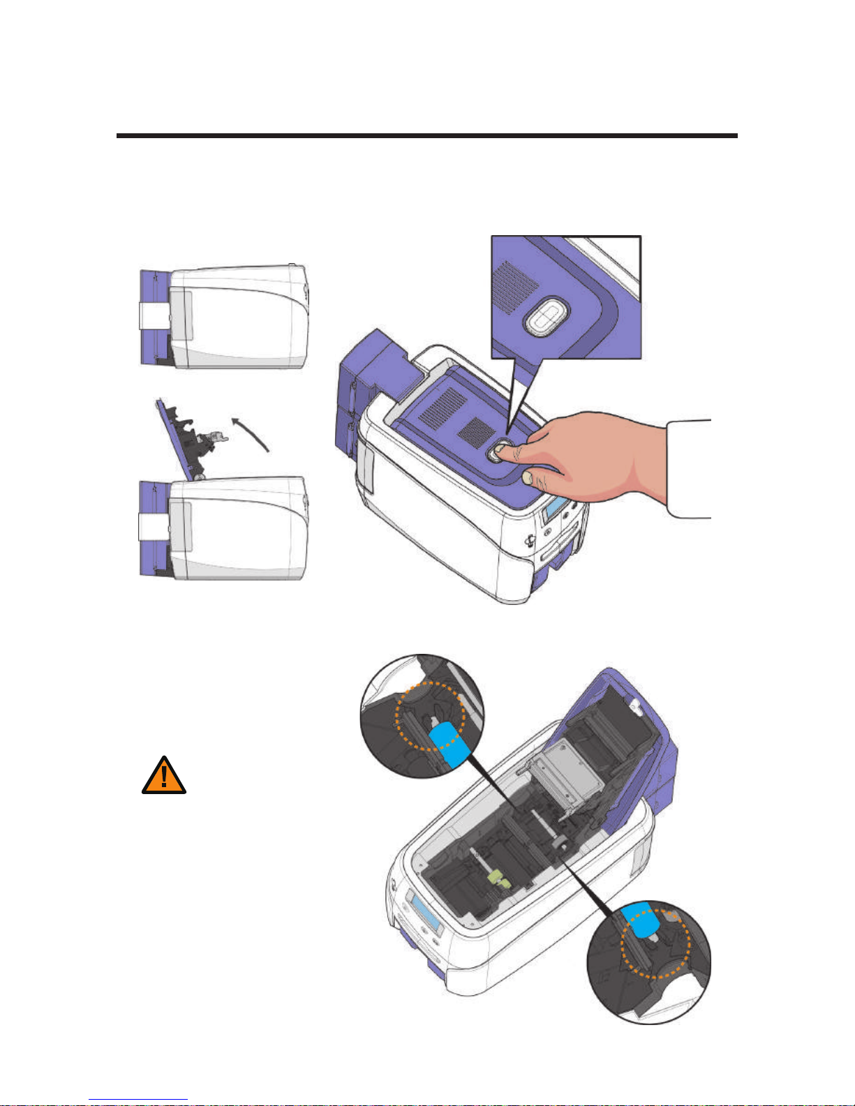
-Load Blue Cleaning Roller
1. Press the “Open” button and lift the Top Cover all the way as shown in
the picture.
Load Blue Cleaning Roller & Ribbon
2. Place the Blue cleaning roller into the “U-shaped holder” and push it
down.
Caution
22
Install printer and ready
- Wash the cleaning roller using running
water and dry every 7 days if the printer
is used frequently or when replacing the
ribbon.
- If the cleaning roller is not cleaned properly,
then the card may be printed unevenly or with
marks across the card.. This may also cause
serious damage to parts (e.g. print head).
Page 23
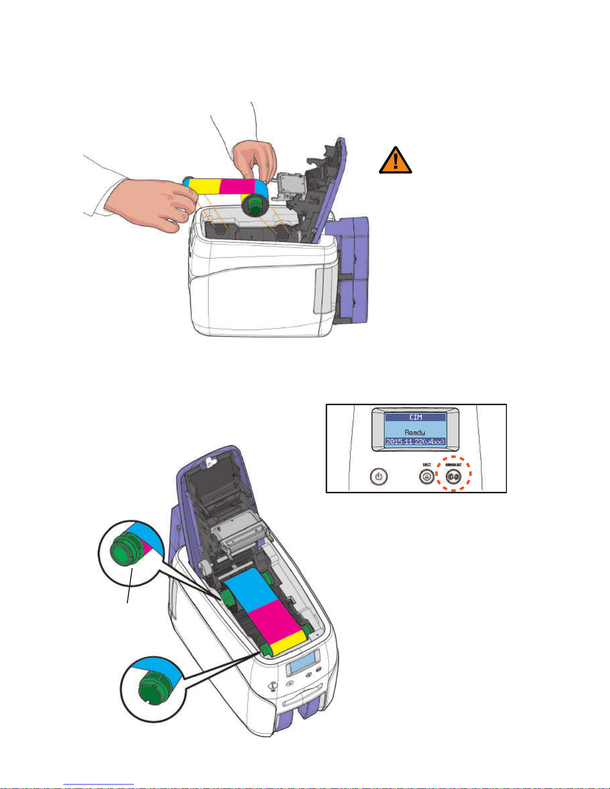
-Load Ribbon
1. Make sure that the ribbon is positioned correctly for loading and rolling.
- Do not close the cover by force
when the ribbon is not placed
properly as this may cause damage.
- If the Top Cover is not closed, the
printer may not print properly (make
sure it is closed completely).
- Make sure that the Ribbon RFID
Tag is positioned correctly.
Caution
23
Ribbon RFID Tag
2. Close the cover and press the “Ribbon
Set” button to complete the process.
CIM User Guide Manual
Page 24
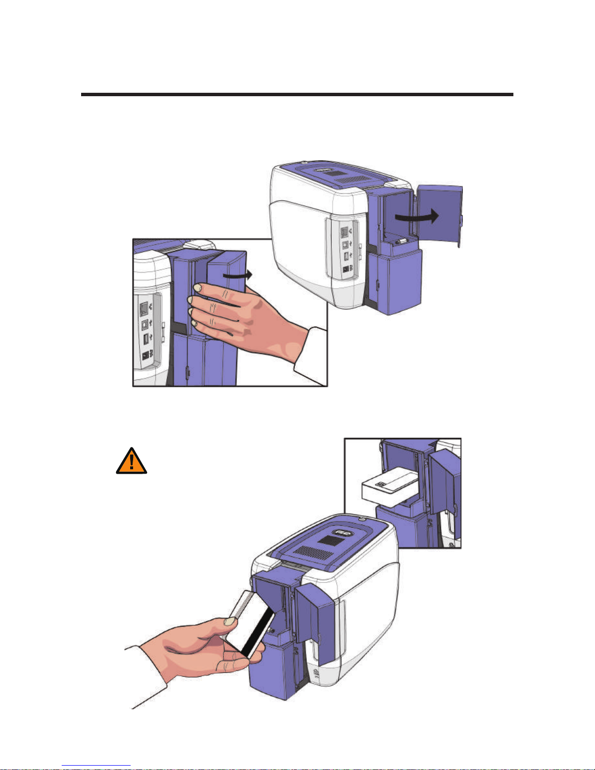
-Place Cards in the Input Hopper
Load Cards
1. Open the Input Hopper by pulling it sideway.
2. Place the cards inside the Input Hopper as shown in the picture.
24
Install printer and ready
- Make sure that the IC chip is facing
the outside.
- If IC Cards are not placed correctly,
then an error will occur.
Caution
Page 25
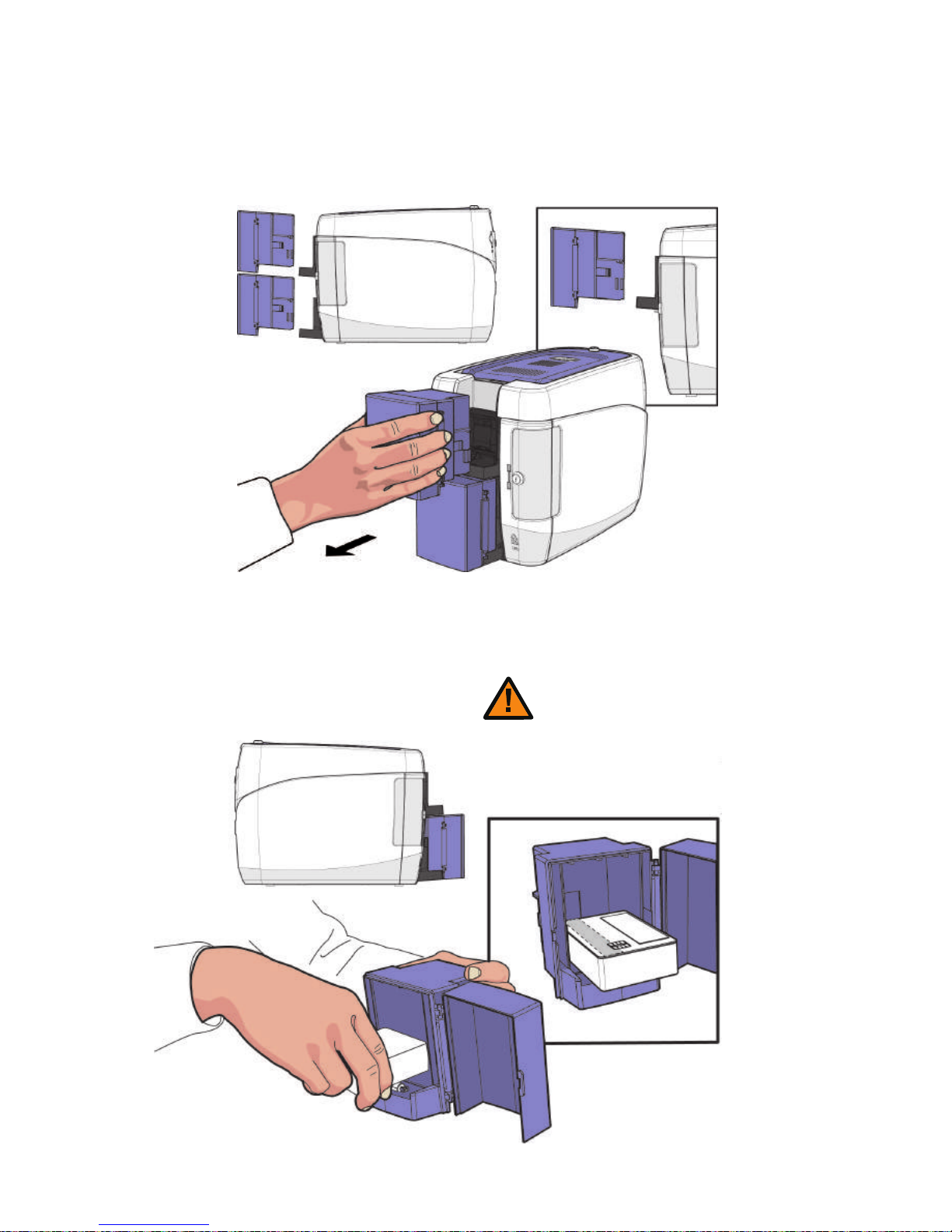
-Place Cards after Removing the Input Hopper
1. Hold the Input Hoppers by the sides, and pull it backward to remove it.
2. Hold the backside of the Input Hopper with one hand and open the cover
with the other. Then, place the cards inside as shown in the picture.
25
- Make sure that the IC chip is facing the outside.
- If IC Cards are not placed correctly, then an error will
occur.
Caution
CIM User Guide Manual
Page 26
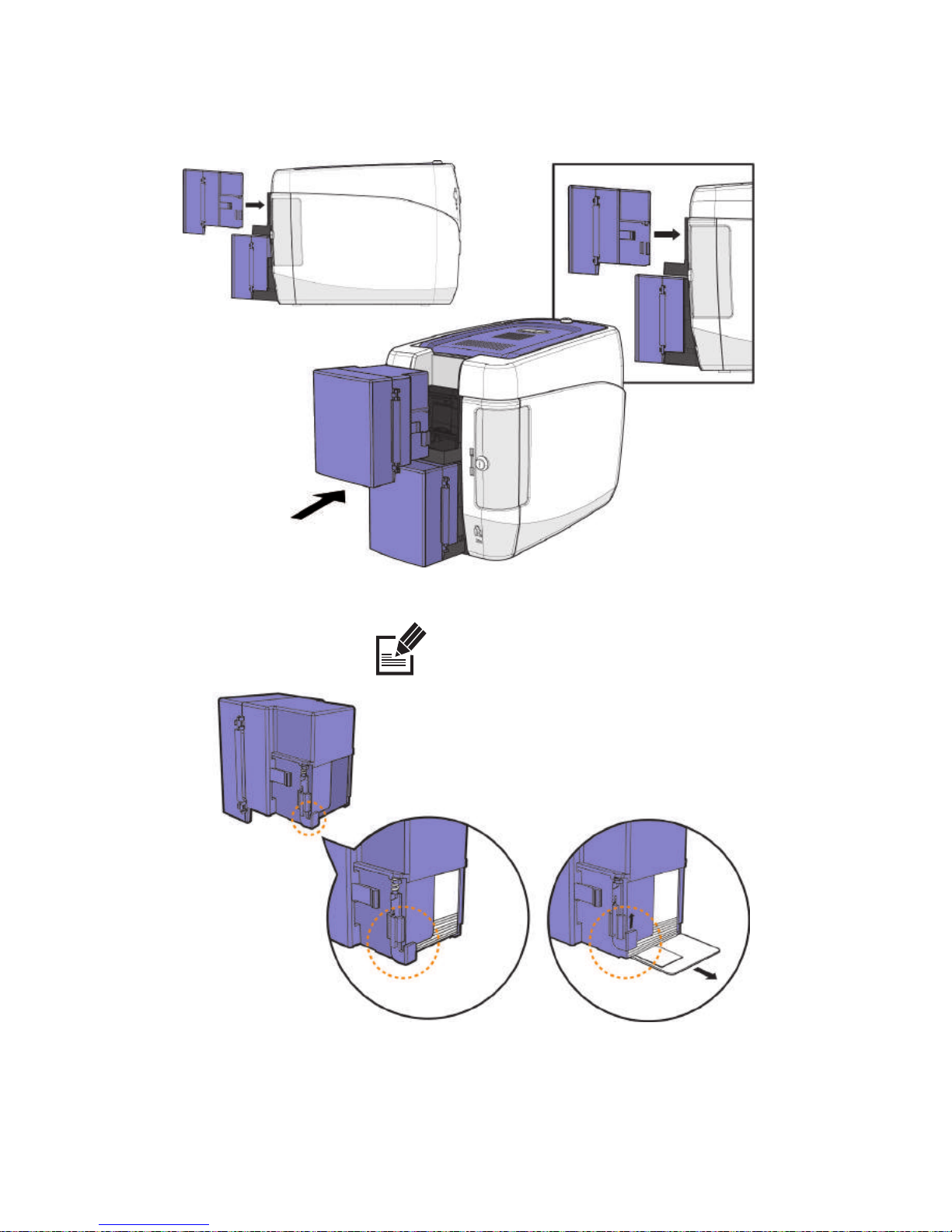
3. Close the cover, and place the Input Hopper in the tray.
Before the card is loaded
When the card is loading
26
Install printer and ready
- The hinge is located where the card is loaded into the
path to prevent displacement.
- The hinge is lifted when the card is loaded into the printer.
Note
Page 27
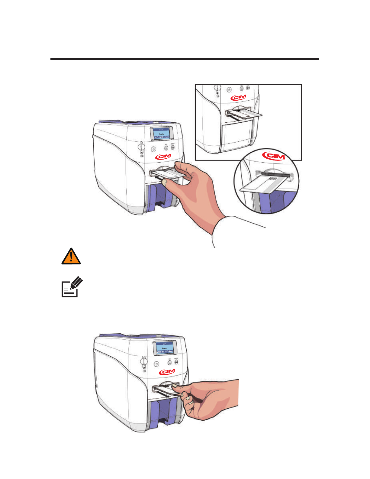
Print Single Card
- The card loaded in the single card slot is printed first, even if there are cards in the
Input Hopper.
1. Insert a card into the front single card slot as shown in the picture.
- This feature is intended for printing both a large quantity of cards (e.g. standard
cards) and a small quantity of cards (e.g. VIP membership cards) without removing
the cards loaded in the input hopper.
- Make sure the IC Chip is on the leading edge into the printer
- If IC Cards are not placed correctly, then an error will occur.
Caution
Note
27
CIM User Guide Manual
Page 28
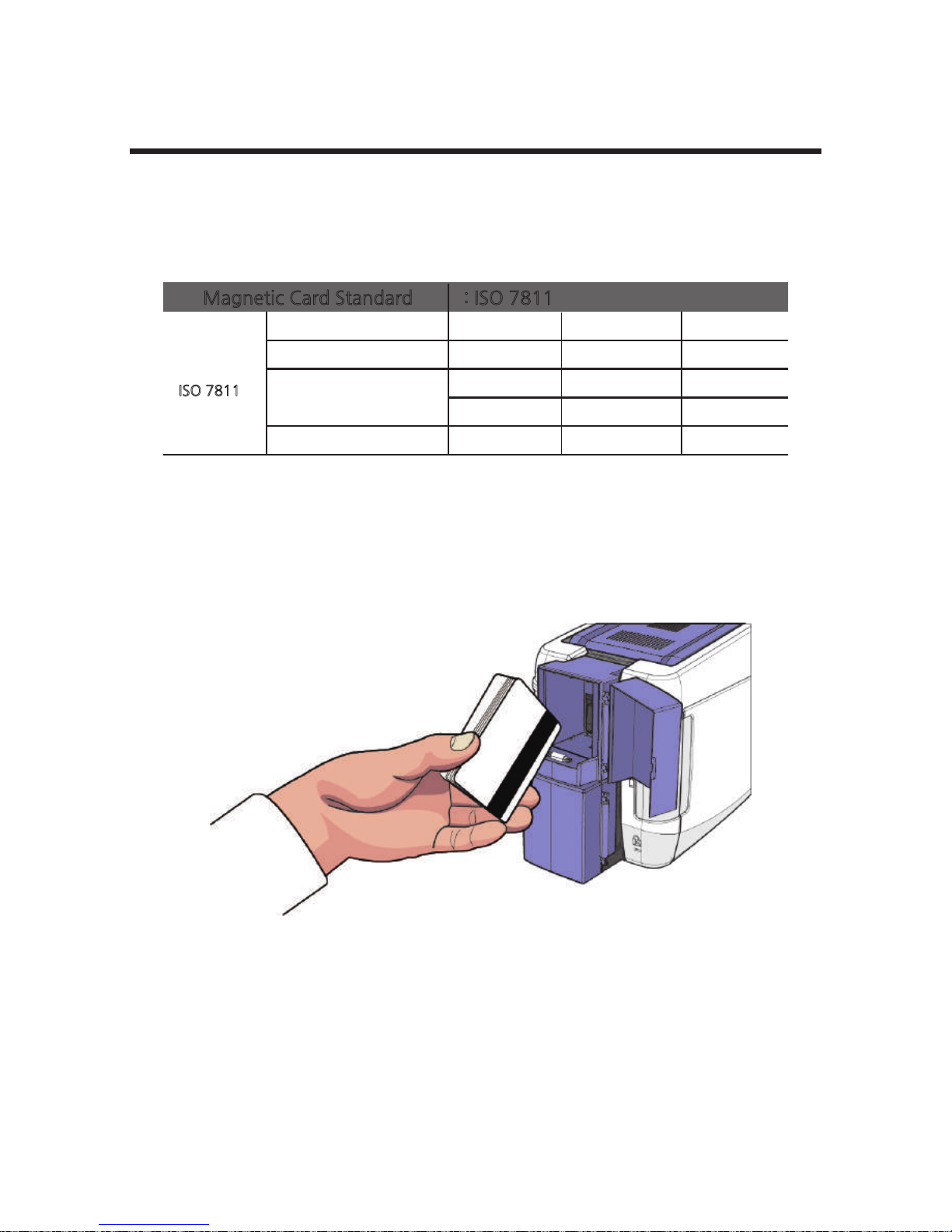
Magnetic Cards
If the printer has the MS module (Single/Triple Track Head), it can encode
information on the Mag. Stripe card.. (ISO 7811 track 1,2,3, Hi-Co/Lo-Co)
ISO 7811
Magnetic Card Standard : ISO 7811
Track
Recording Density
Capacity
Start / End code
Track 1 Track 2 Track 3
210 BPI 75 BPI 210 BPI
79 Characters 40 Characters 107 Characters
(7 bit code) (5 bit code) (5 bit code)
%/? ;/? ;/?
When loading Mag. Stripe cards, make sure the magnetic stripe is facing
down and on the left side as shown in the pictures.
28
Install printer and ready
Page 29
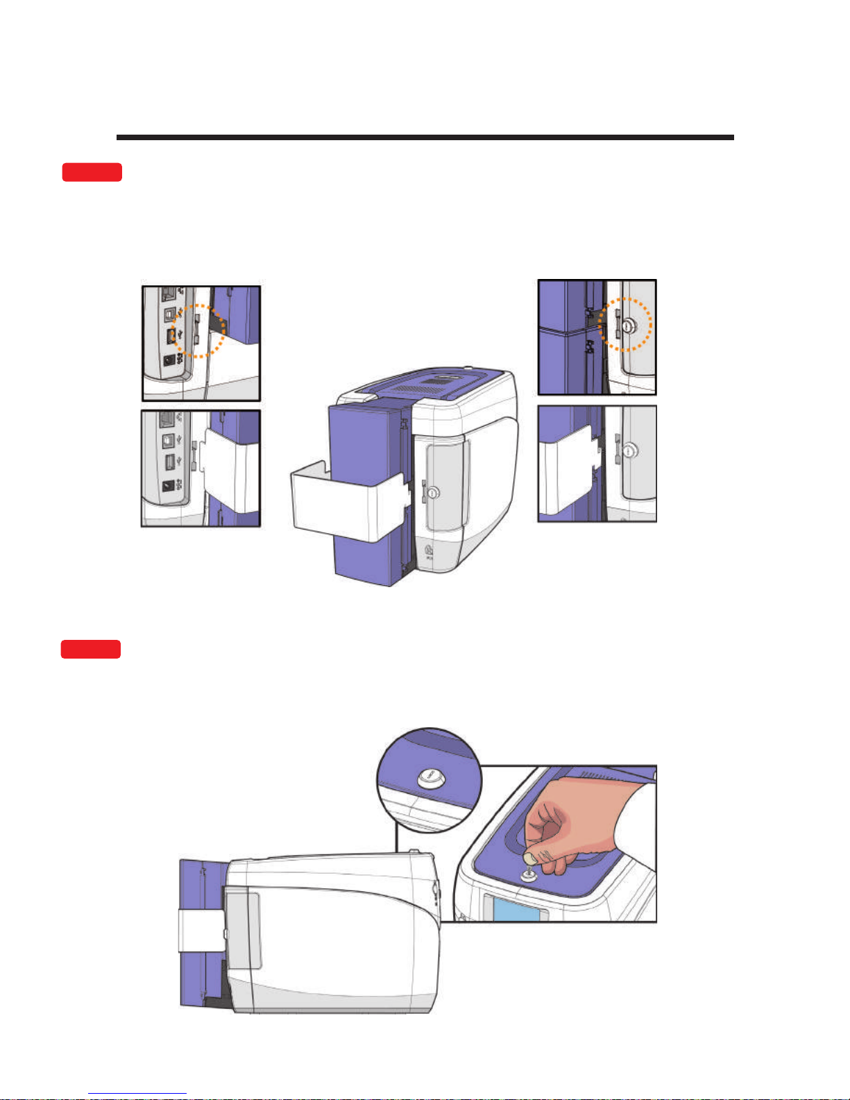
-Input Hopper Lock
Input Hopper & Ribbon Lock
1. Place the Input Hopper Lock in the area highlighted by the circle and push it
down to fix it in the position. Then, use the Lock Key to lock it.
-Ribbon Lock
1. Use the Lock Key to lock the Top Cover.
OPTION
OPTION
29
CIM User Guide Manual
Page 30
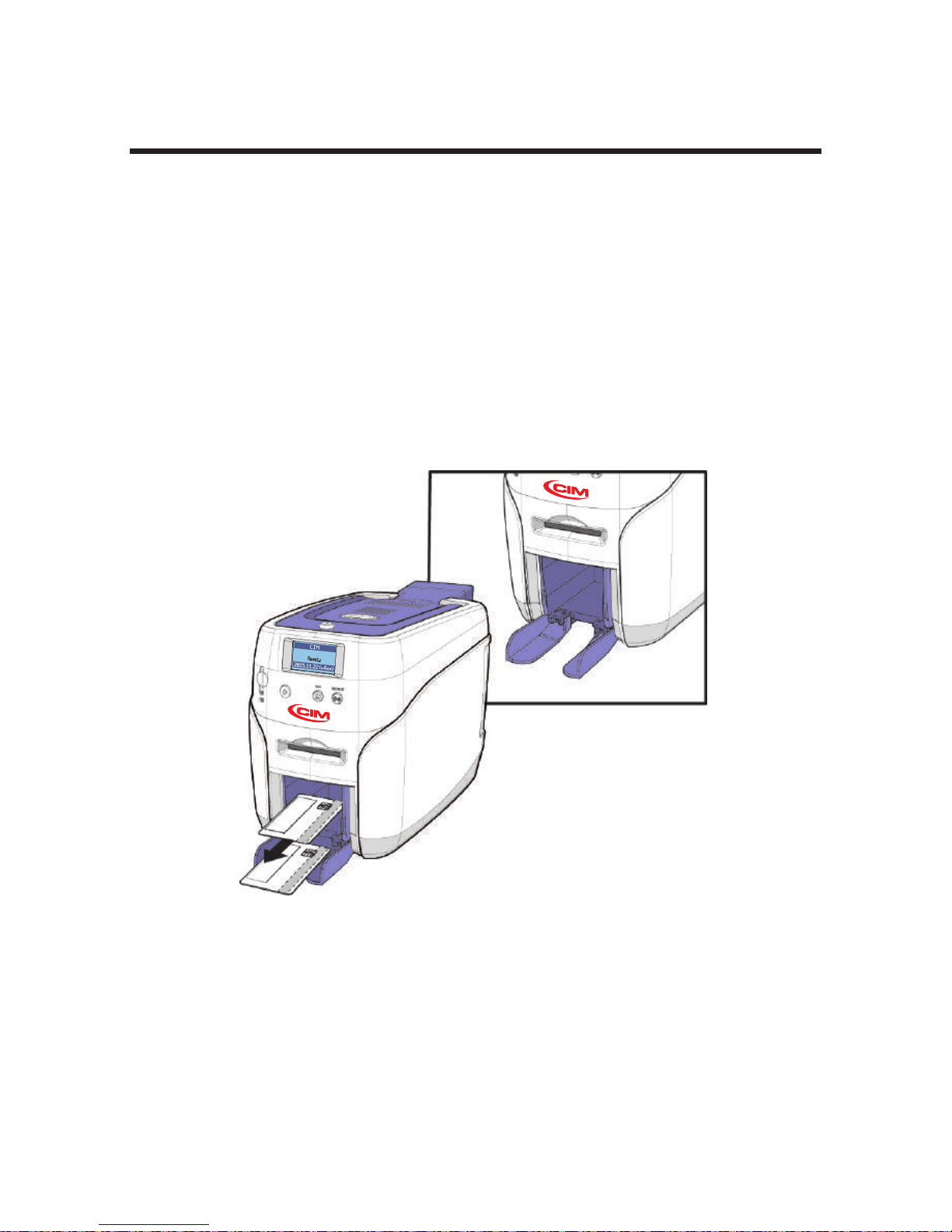
-Open the Output Stacker Cover and Remove
the Cards
Install/Remove Output Stacker
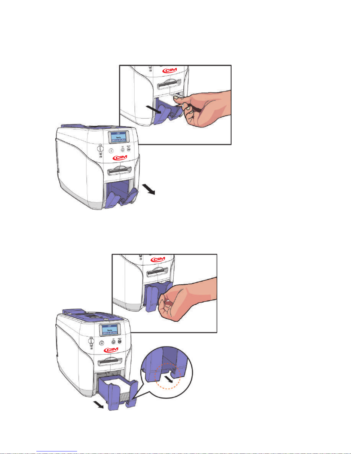
The Output Stacker can be installed or removed as follows:
Option 1: Open the Output Stacker cover and remove the cards.
Option 2: Use the spring load to remove a small quantity of cards.
Option 3: Remove the Output Stacker and the cards.
Lower the Output Stacker cover until it latches as shown in the picture.
Use this method when printing a small quantity of cards and check the
results right away.
30
Install printer and ready
Page 31
-Use the Spring Load to Remove a Small Quantity
of Cards.
- Remove the Output Stacker and the Cards.
Push the Output Stacker
and pull it forward and
then pull it back to remove
it as shown in the picture.
This method is recommended for printing
more than 50 cards,
and up to 60 cards can
be loaded in this way.
31
This method is recommended when printing
fewer than 5 cards.
The Output Stacker is spring loaded so that
it returns to its original position when the
cards are removed.
CIM User Guide Manual
Page 32
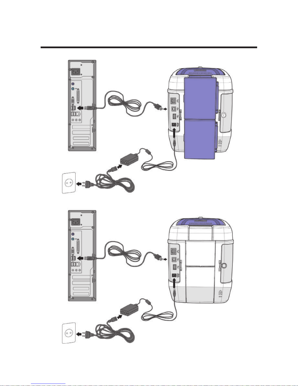
Connect Power & Communication Cables
32
Install printer and ready
Power Adaptor
Power Cable
USB Cable
Power Adaptor
Power Cable
USB Cable
Single, Double-sided Printing
Single, Double-sided Printing
Page 33
Install Program
-System Requirements
① Supported Operating Systems
- CPU: Pentium III 1 Ghz (Pentium IV 1.5 Ghz is recommended)
- Memory: 128 MB (512 MB is recommended)
- HDD: 1 GB (5 GB is recommended)
- Internet Explorer 5.5 or higher (6.0 is recommended)
② Recommended Specifications
You need to log in as an Administrator to install or uninstall the driver
on Windows 2000/XP/Vista/7/8.
Note
-Install Software
It is recommended to close all programs before installing the software.
Caution
1. Insert the CD into the PC’s CD-ROM drive, and the setup program will
start automatically. If the program does not start automatically, then go to
the CD-ROM drive’s root directory and run “install.exe” manually.
① Install Software Using Local Port(USB)
- Windows 2000
- Windows XP (32/64bit)
- Windows Vista (32/64bit)
- Windows 7 (32/64bit)
- Windows 8 (32/64bit)
- Windows 10 (32/64bit)
- Windows 2012 R2 Server
- Windows 2008 Server
- Windows 2003 Server (32/64bit)
33
CIM User Guide Manual
Page 34
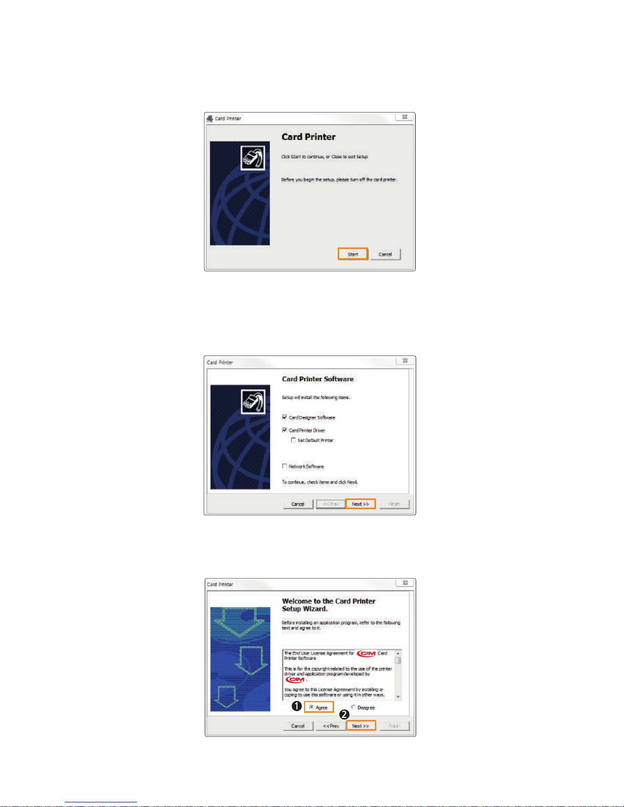
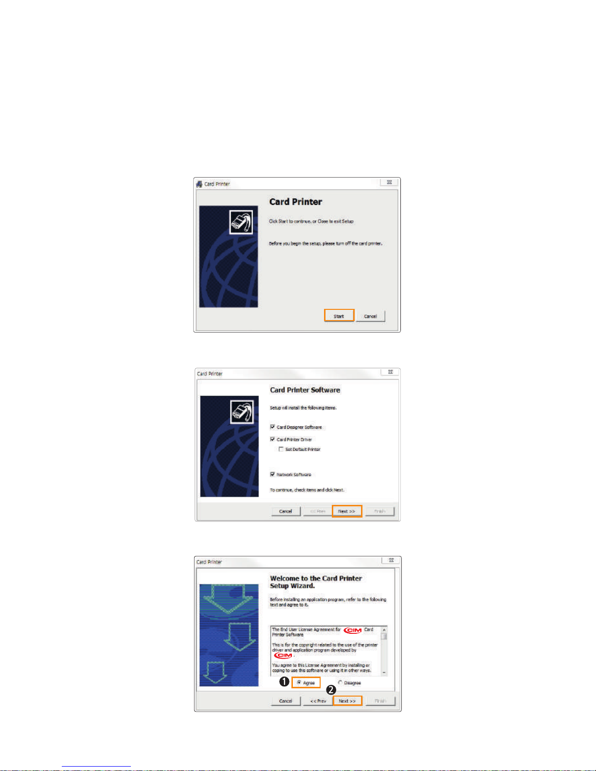
2. The initial screen of the Card Printer Driver is displayed as shown in
the picture. Click “Start” to install the program.
3. Select the software to install and click “Next” to proceed.
(Card Designer Software, Card Printer Driver)
4. Read the Terms of Use and check “Agree”. Then, click “Next” to proceed.
34
Install printer and ready
Page 35
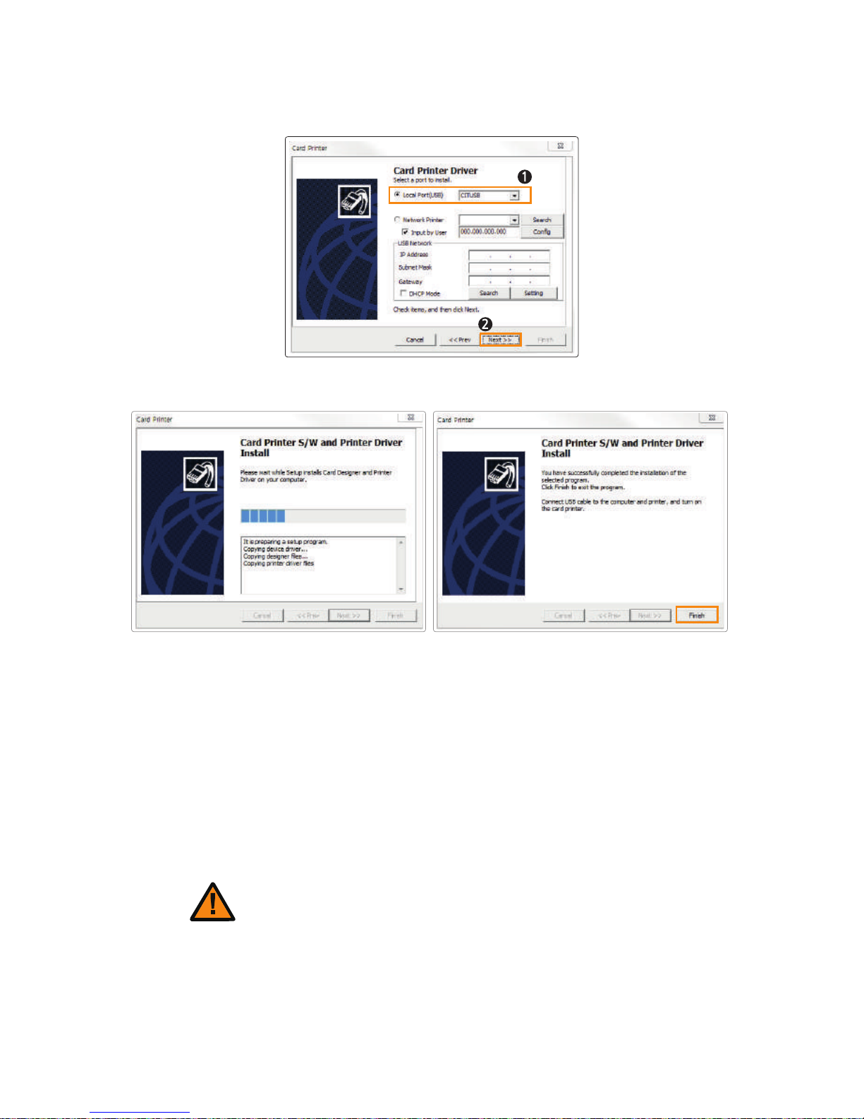
5. Specify the Port Type and click “Next”.
(Select “CITIUSB” when connecting the printer directly to the PC using a USB cable.)
6. Click “Finish” to complete the installation process.
For "Card Printer Driver", check:
"Start → All Programs → CIM → Printer"
Go to "Devices and Printers" and make sure "Card Printer" has been
installed.
7. Make sure that the following programs are installed.
For "Card Designer Software", check:
"Start → All Programs → CIM → Card Designer"
1. Insert the CD into the PC’s CD-ROM drive and the setup program will
start automatically. If the program does not start automatically, then go to
the CD-ROM drive’s root directory and run “install.exe” manually.
② Install Software for Network Printer
Conect the LAN cable between the Ethernet port and the router/server
PC should be connected to network.
Caution
35
CIM User Guide Manual
Page 36
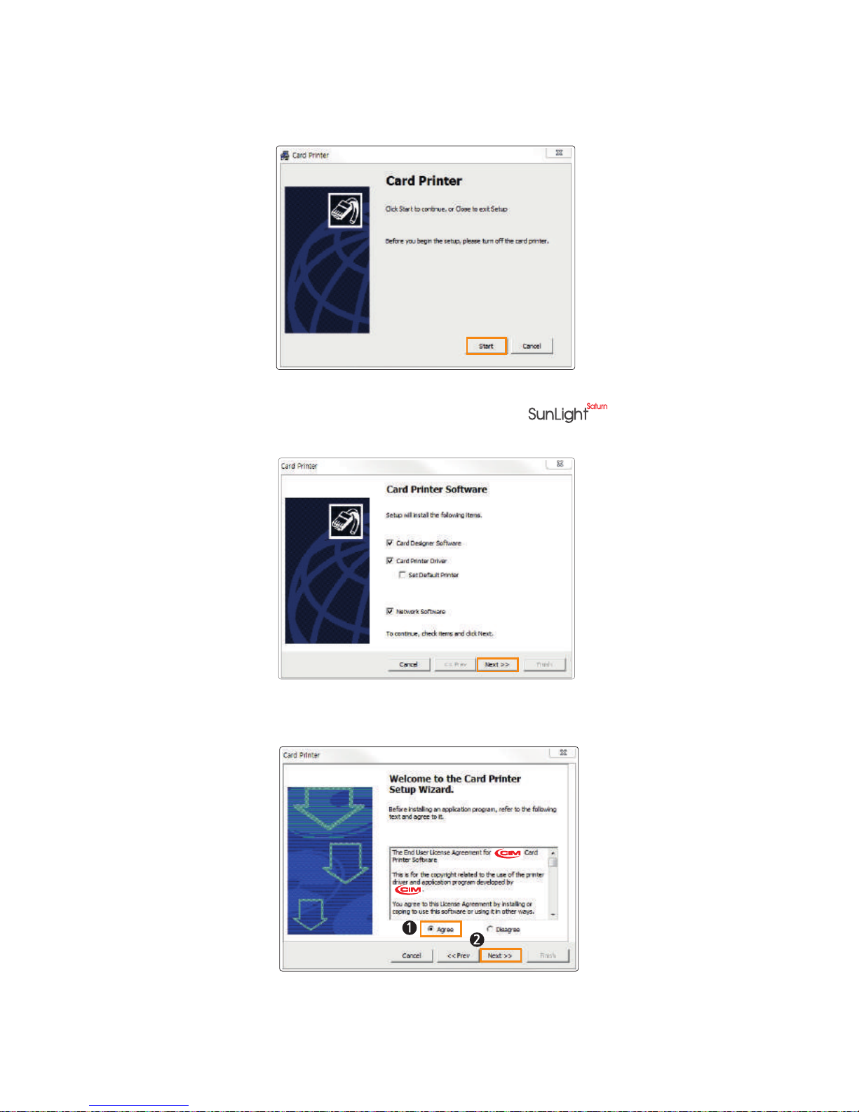
2. The initial screen of Card Printer Driver is displayed as shown in the picture.
Click “Start” to install the program.
3. Select the Printer Driver & Network Driver options to install and click
“Next” to proceed.(Connect a LAN cable to the series-NX0 with
Ethernet option and select “Network Software”.)
4. Read the Terms of Software and check “ Agree”. Then, click “Next” to proceed.
5. Click "Finish" to complete the installation process. Finish.
36
Install printer and ready
Page 37
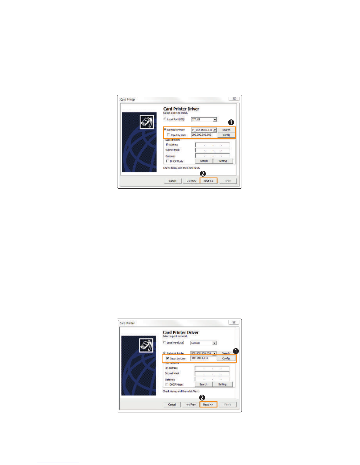
Select “Network Printer” and the printer IP address will be displayed if it is
connected to the network. Click “Next” to continue.
5. Install Network Printer
5-2. Manual Installation
If the printer's IP address is not shown as in the picture, then check the
following.
(Make sure that the printer is in the same IP range.)
(1) If they are in the same IP range
For example, if your PC's IP address is 192.168.0.xxx, then the printer's IP
address must be 192.168.0.yyy.
If they are not in the same IP range, check "Input by user" and enter the
printer's IP address. Then, click "Next" to proceed.
5-1. Auto Installation
37
CIM User Guide Manual
Page 38
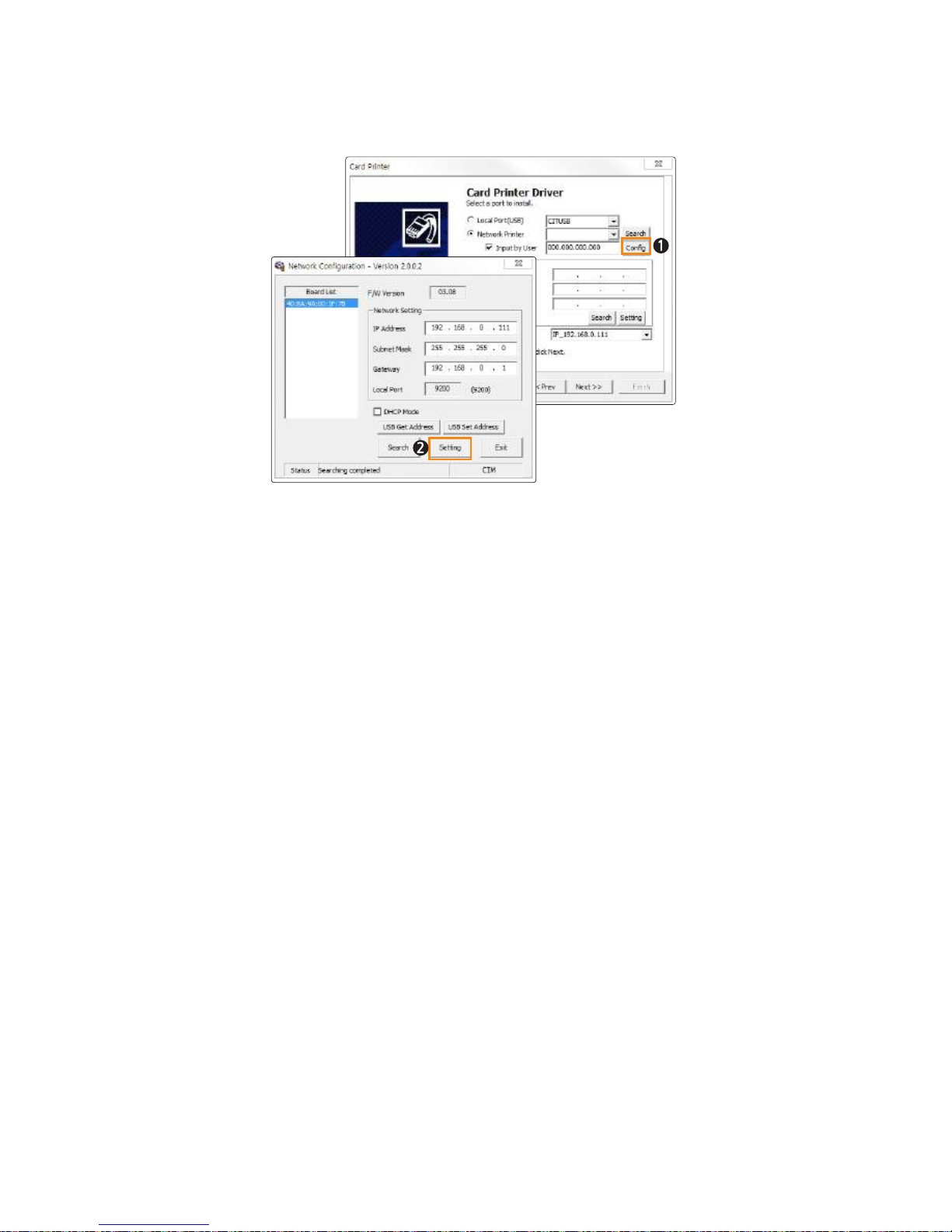
(2) If they are in the same IP range, but the printer cannot be found
Check “Input by user” and click “Setting”.
When the Network Configuration window pops up, the available printers will
be displayed.
Check the IP Address, Subnet Mask and Gateway and click "Setting".
Check DHCP to enable DHCP mode and click “Setting”. If the settings are
entered correctly, the printer will initialize.
If the IP address and Board List are not specified in the Network Configuration
window, then they may be in a different IP address range or the printer is not
connected to the network. You will need to check your network settings.
38
Install printer and ready
Page 39
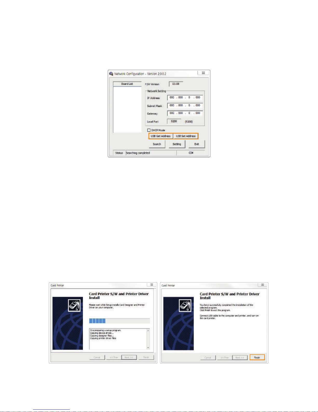
6. Click “Finish” to complete the installation process.
5-3. Manual Installation (Connect to the printer using a USB connection)
(1) Retrieve Address via USB
Connect the printer to a PC using USB connection and click "USB Get
Address" to check the device's IP Address, Subnet Mask, Gateway and MAC
address.
(2) Set Address via USB
Check the values retrieved through "Retrieve Address via USB".
Enter the IP Address, Subnet Mask, and Gateway, and click "Retrieve
Address via USB"
If the printer is not automatically detected, connect to the printer using a USB
connection and configure the network settings.
39
CIM User Guide Manual
Page 40
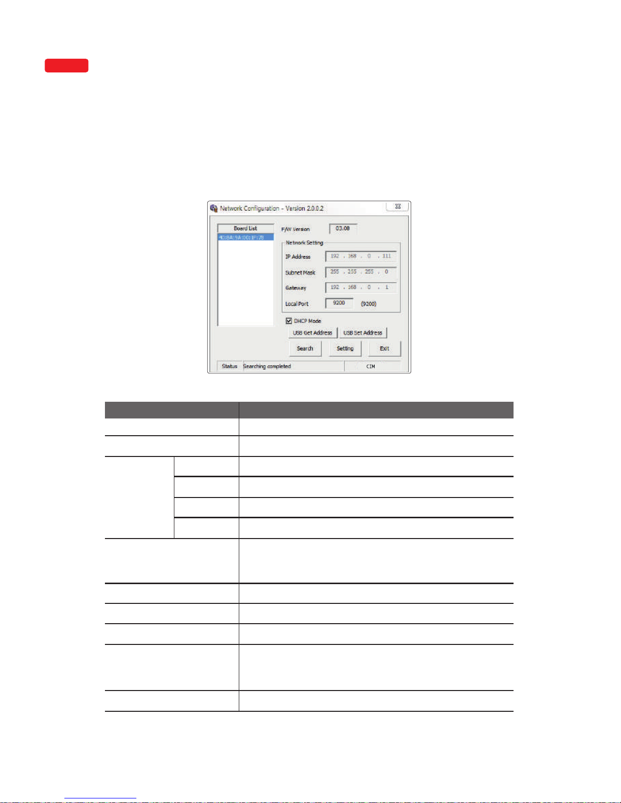
"Start → All Programs → CIM → Network"
After installing the printer driver, go to the following path to configure network
settings. (This feature is only supported by some models.)
③ Configure Network Settings
1) Network Configuration Window
Board List Displays a list of detected printers.
Firmware Version
Displays the firmware version of the selected network board.
IP Address
Displays the IP address of the selected network board.
Item Description
Subnet Mask Displays the subnet mask of the selected network board.
Gateway
Displays the gateway of the selected network board.
Local Port
Sets the port of the network printer.
DHCP Mode
Sets the IP address automatically for network environments that
support DHCP. Otherwise, you need to retrieve the allocated IP
address and enter manually.
USB Get Address
Retrieves the printer’s network address USB.
USB Set Address
Sets the printer’s network address via USB.
Search
Searches the printer’s network.
Setting
Saves the new network information to the printer. After the
settings are applied, the printer reboots. This reboot takes
about 10 seconds.
Exit
Exit the program.
OPTION
Network
Setting
"Start -> Apps (by name) -> CIM -> Network setting"
40
Install printer and ready
Page 41
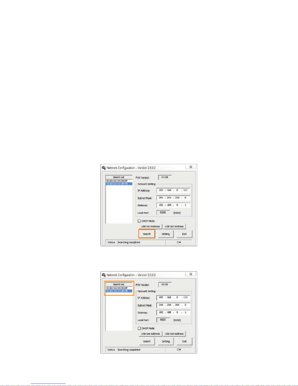
2) DHCP (Dynamic Host Configuration Protocol)?
DHCP (Dynamic Host Configuration Protocol)?
DHCP is a network protocol that automatically allocates TCP/IP to the client PC.
The DHCP server sends the client's network settings (e.g. IP Address,
Subnet Mask, Gateway, DNS server) automatically.
If "Obtain an IP Address automatically" is set in your TCP/IP settings, it means
that DHCP Mode is enabled.
3) Network Setting - Automatic (DHCP supported)
1. Go to “Start → All Programs → CIM → Network” and click OK to
open the settings window.
2. In the Network Configuration window, click “Search” to search the connected
network board.
3. Select the MAC Address from the Board List.
41
CIM User Guide Manual
Page 42
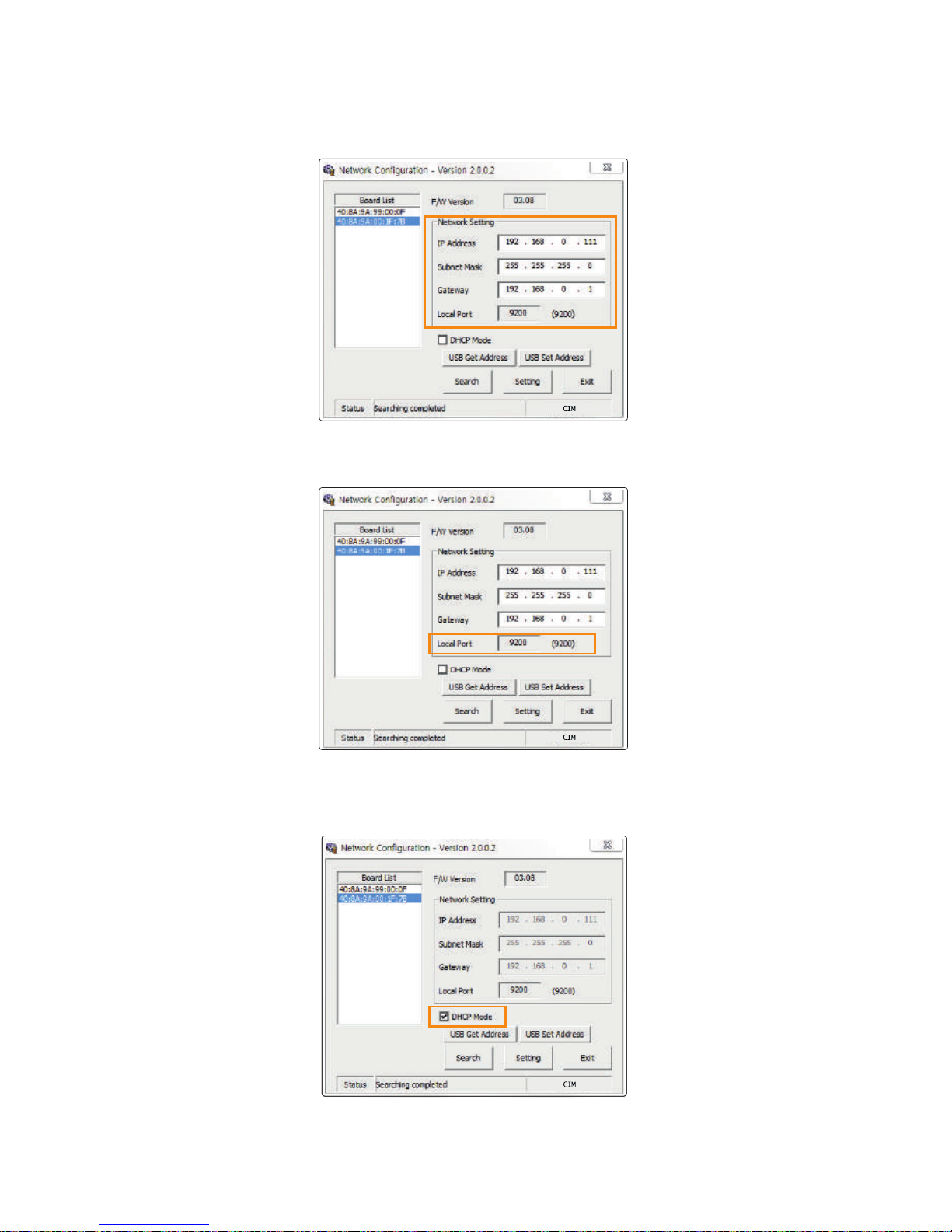
5. Set the Local Port to 9200 (cannot be changed).
4. The IP Address, Subnet Mask and Gateway are allocated automatically
by the DHCP server, and there is no need to set the values.
6. Check the DHCP Mode.
42
Install printer and ready
Page 43
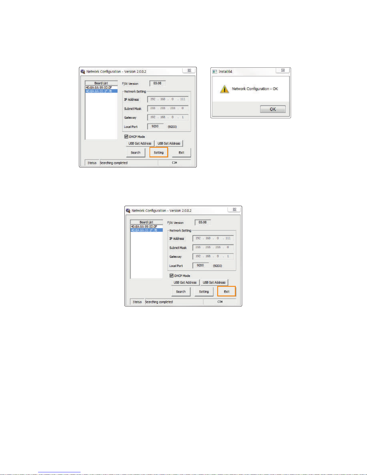
7. Click "Setting". This takes about 30 seconds.
When the settings complete, the printer reboots automatically and retrieves
a new IP address from the server.
8. Click "Exit" to complete the network configuration process.
43
CIM User Guide Manual
Page 44
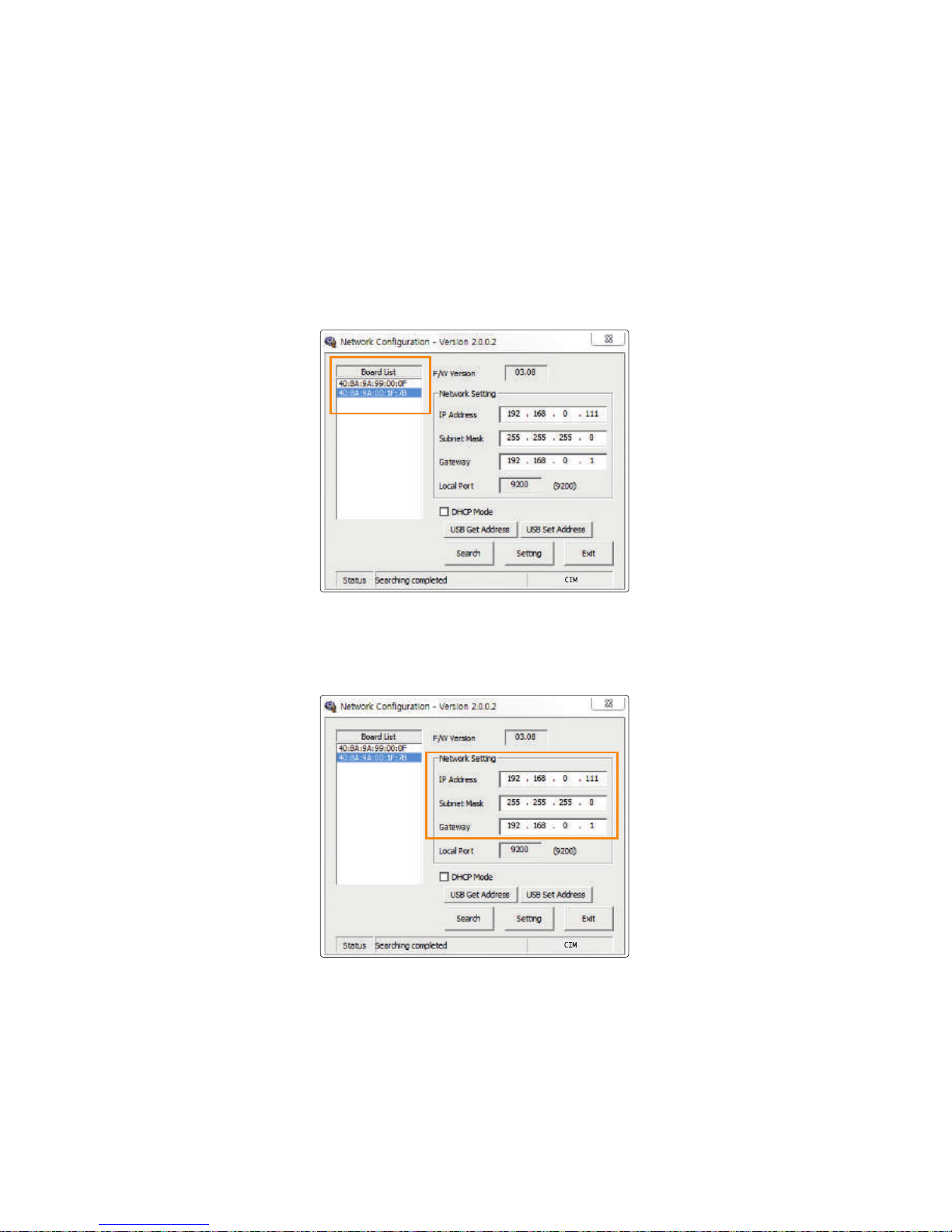
4) Network Setting - Manual
‘1.Go to “Start → All Programs → CIM→ Network” and click “OK”
to open the settings window.
Retrieve the IP Address, Subnet Mask and Gateway to be used by the
printer from the network administrator.
2. Select the MAC address from the Board List.
3. Enter IP Address, Subnet Mask and Gateway.
44
Install printer and ready
Page 45
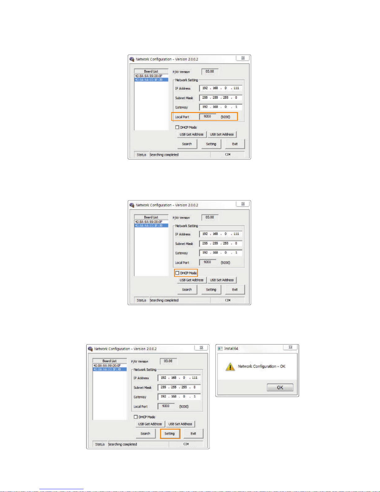
4. Set the Local Port to 9200 (cannot be changed).
5. Do not check the DHCP Mode. Make sure to leave the box unchecked.
6. Click "Setting". This takes about 30 seconds. When the settings
complete, the printer reboots automatically.
45
CIM User Guide Manual
Page 46
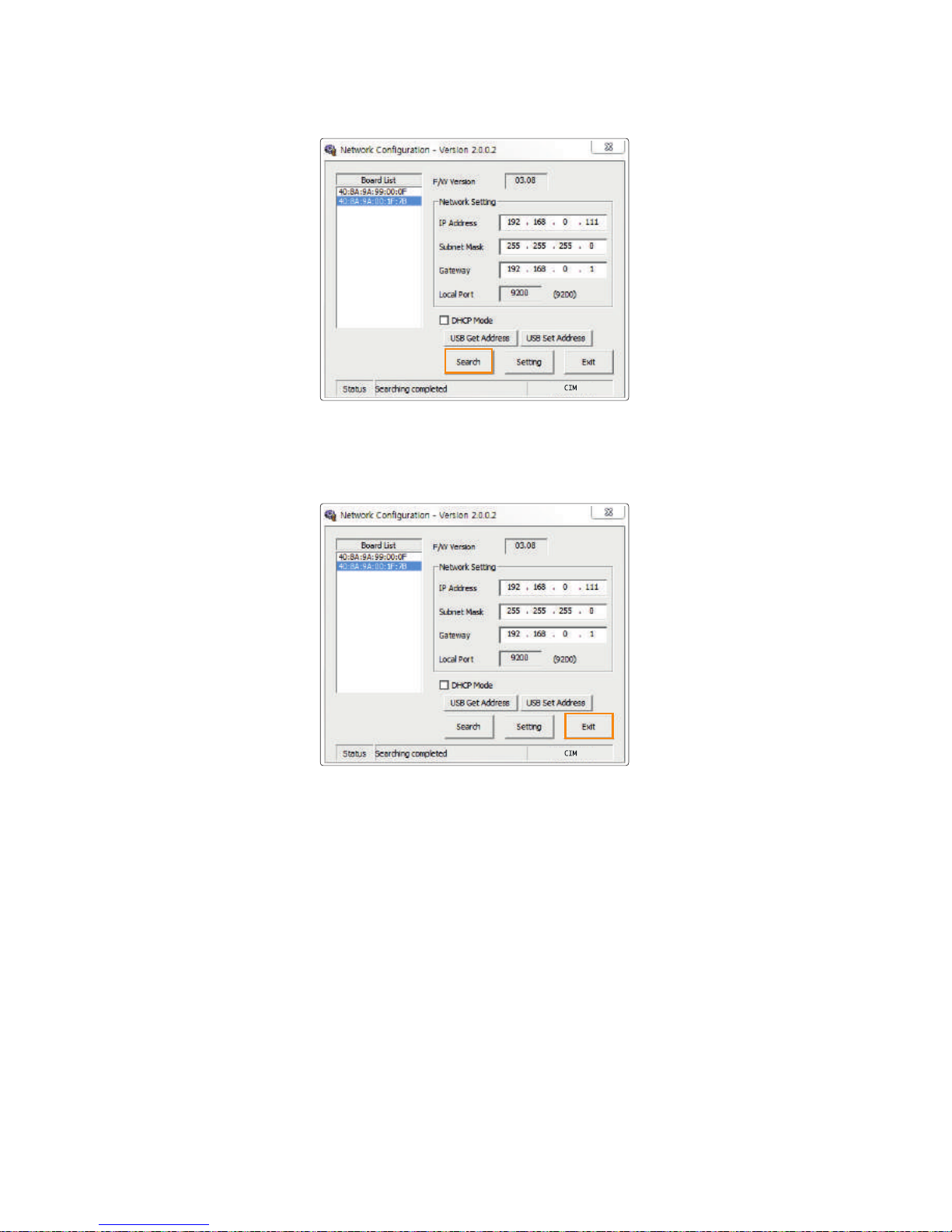
7. Click "Search" to check the network configuration.
8. Click "Exit" to complete the network configuration process.
46
Install printer and ready
Page 47
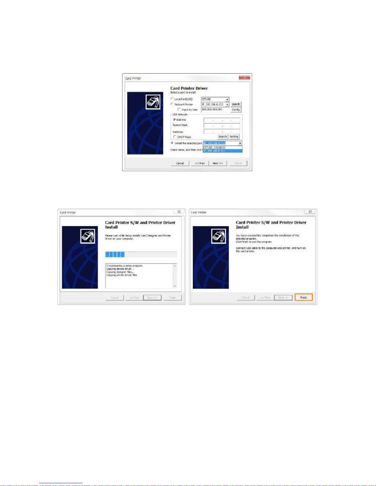
1. Insert the CD into the PC’s CD-ROM drive and the setup program will start
automatically. If the program does not start automatically, then go to the
CD-ROM drive’s root directory and run “install.exe” manually.
④ Install Software from the List of Connected Devices (Optional)
2. The initial screen of the Card Printer Driver is displayed as shown in
the picture. Click “Start” to install the program.
3. Select the option to install and click “Next” to proceed.
4. Read the Terms of Use and check “Agree”. Then, click “Next” to proceed.
47
CIM User Guide Manual
Page 48
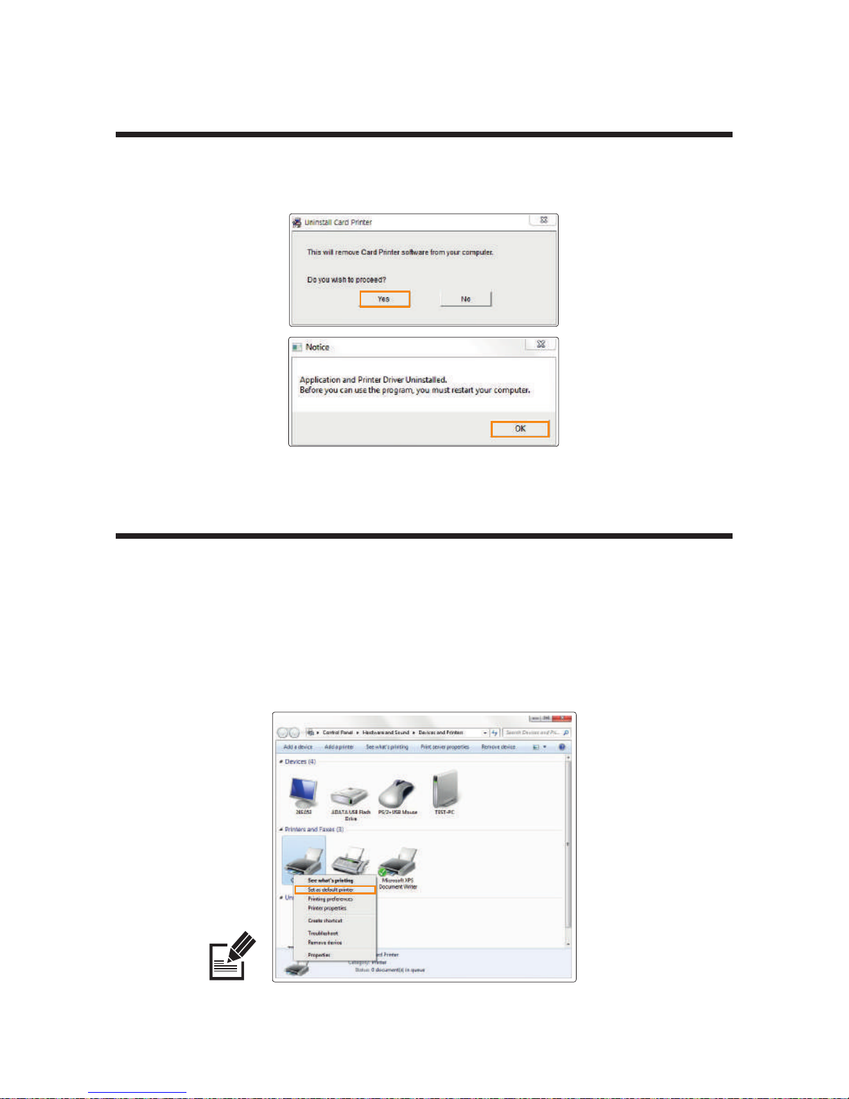
6. Click “Finish” to complete the installation process.
5. Select “Install the Selected port” and it displays the printers that can be
connected to a PC. Printers on other networks are not included in the list.
Click “Next” to proceed.
Go to "Devices and Printers" and make sure "Card Printer" has been
installed.
7. Make sure that the selected items are installed.
48
Install printer and ready
Page 49
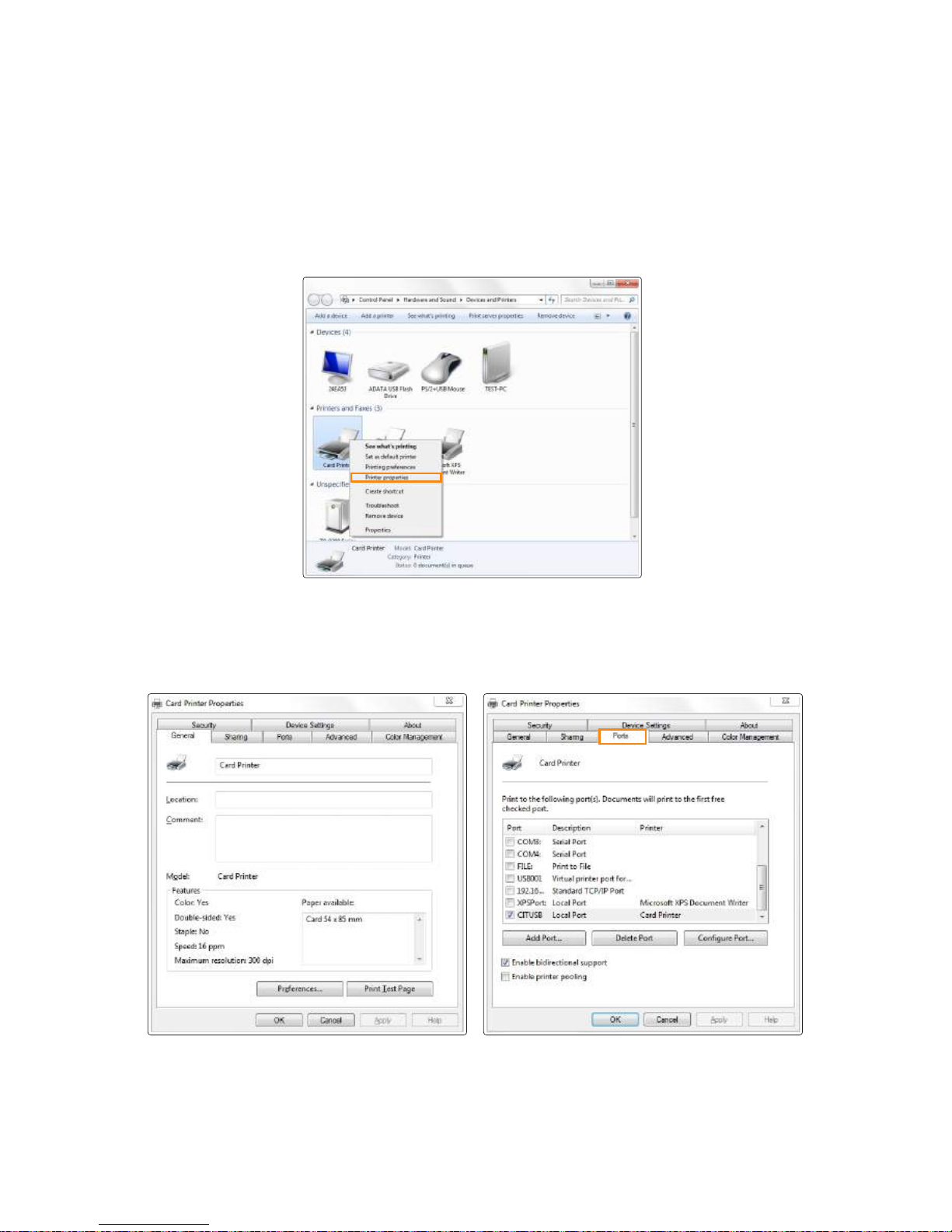
-Set as Default Printer
1. Go to “Hardware and Sound → Devices and Printers” in the “Control Panel”.
2. Right-click “Card Printer” and select “Set as default printer”.
Use this printer settings when there are no other printers
connected to your PC.
Note
1. Go to Control panel → Uninstall Program → Select “Card Printer” on the list
→ Select “Uninstall”
You can change the printer settings using the functions provided by the
printer driver.
Uninstall Program
Print Cards
49
CIM User Guide Manual
Page 50
3. Select “Ports (or Advanced)” tab in the “Card Printer Properties”.
-Change Printer Port (Using the Printer Driver)
1. Go to “Hardware and Sound → Devices and Printers” in the “Control Panel”.
2. Right-click “Card Printer” and select “Properties (or Printer Properties)”.
50
Install printer and ready
Page 51
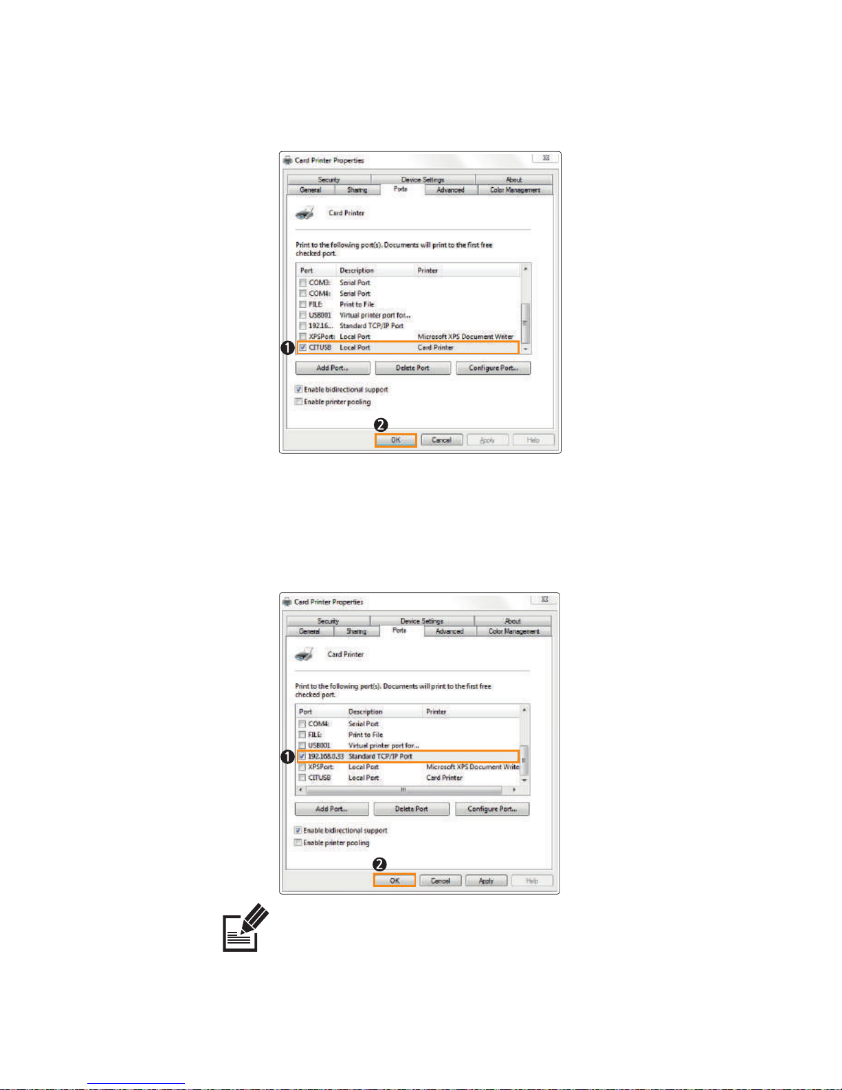
Network Port: Refer to "Configure Network Settings" (P40) and select
the port (IP Address) accordingly.
Note
When the driver is installed successfully, "Two-Way Communication" will be selected automatically.
If there is any problem printing through the network port, make sure to disable "Two-Way
Communication".
4. Select the port you want to use and click “OK”.
USB Port: CITUSB (Local Port)
51
CIM User Guide Manual
Page 52
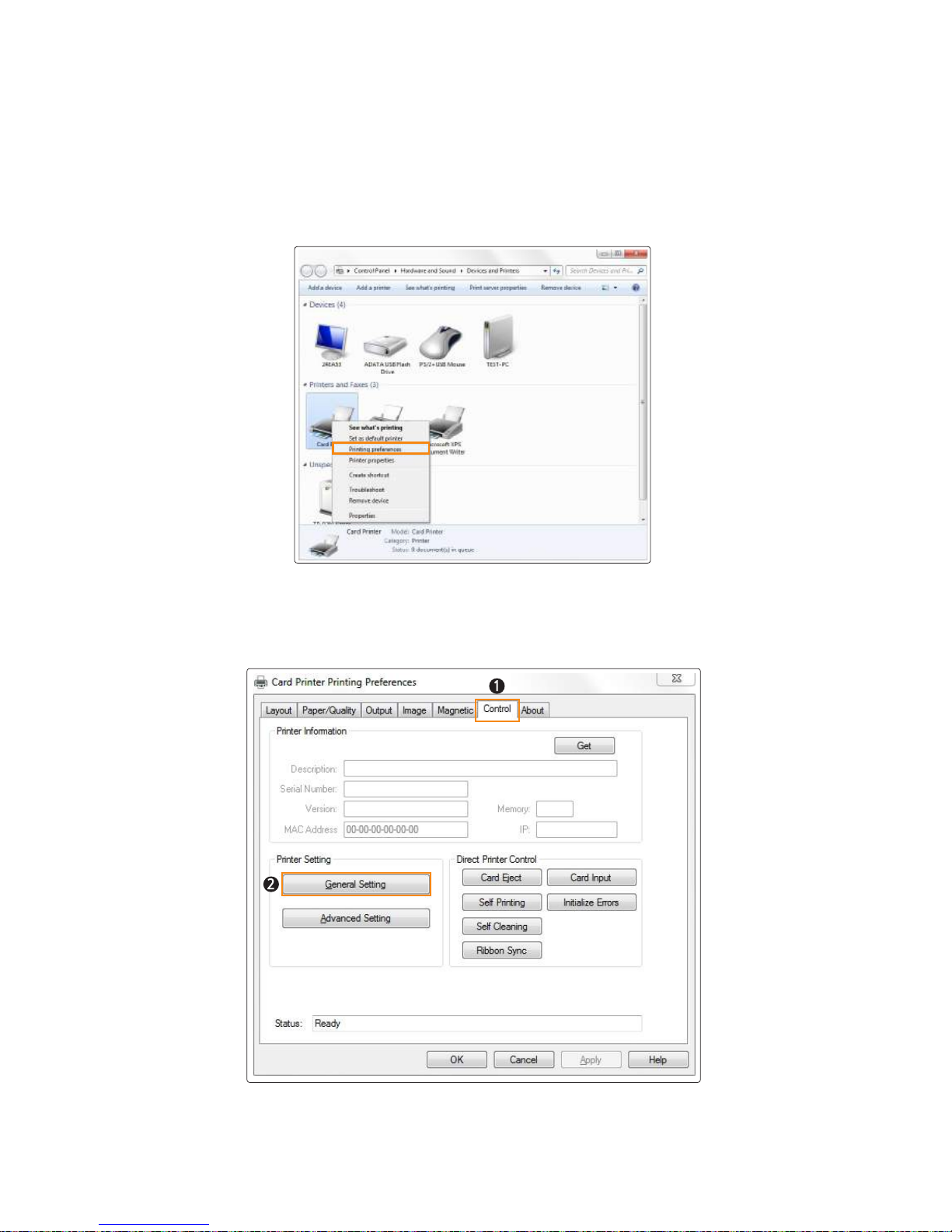
-Select Input Hopper in the Printer Settings
1. Go to “Hardware and Sound → Devices and Printers” in the “Control Panel”.
2. Right-click “Card Printer” and select “Printing Preferences”.
3. Go to “Printer Setting → General Setting” in the “Control” tab.
52
Install printer and ready
Page 53
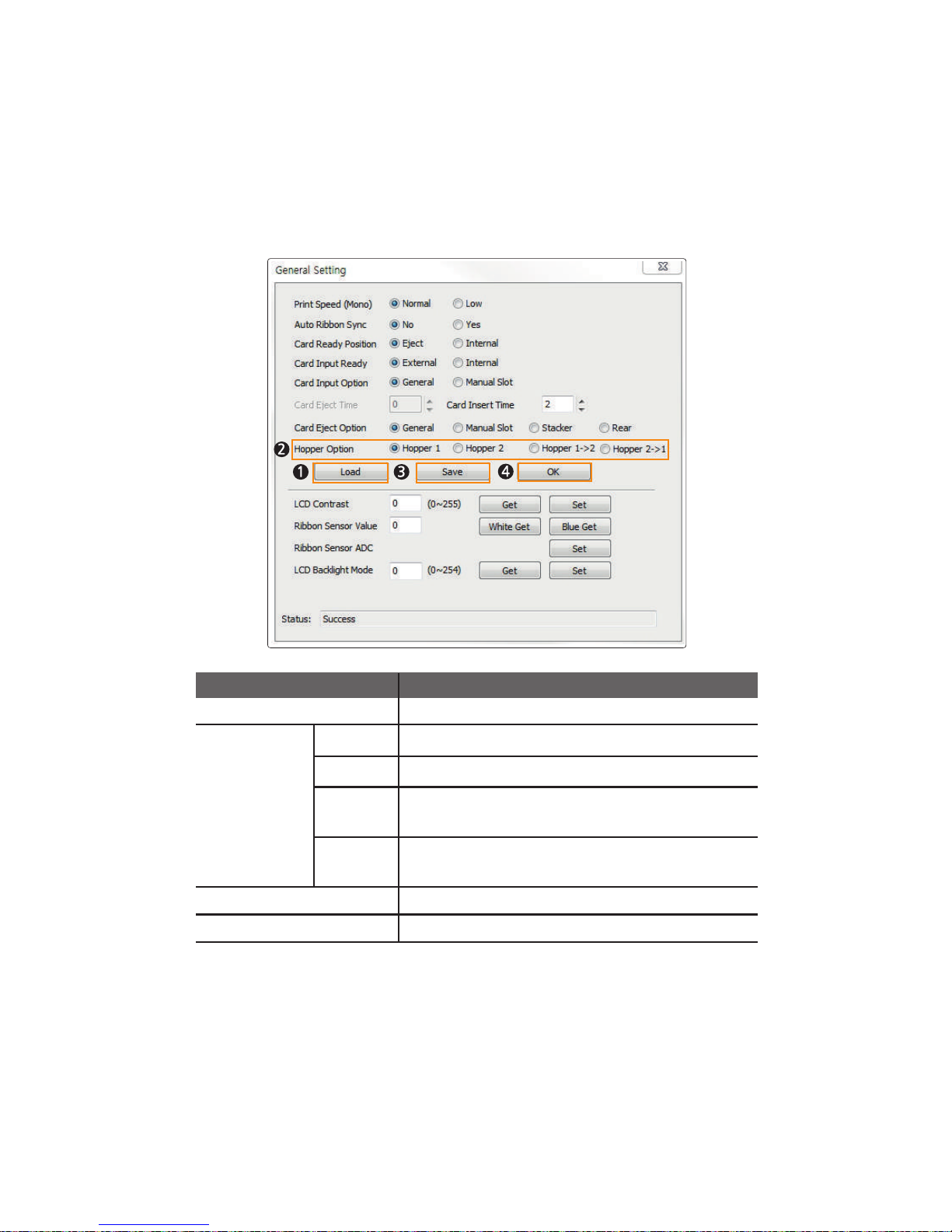
3. Make sure that the printer is on, and click “Load” to activate the Input
Hopper Option.
4. Select “Hopper Option” and click “Save” to save the new settings.
5. Click “OK” to close the General Setting tab.
Load Load the General Settings of the printer.
Hopper Option
Feed cards only from the upper Input Hopper.
Feed cards only from the lower Input Hopper.
Item Description
Feed cards from the upper Input Hopper first. When it is
empty, the printer feeds cards from the lower Input Hopper.
Save the General Settings of the printer.
Hopper 1
Hopper 2
2 →1 reppoH
Hopper 2→ 1
Feed cards from the lower Input Hopper first. When it is
empty, the printer feeds cards from the upper Input Hopper.
Close the General Settings window.
Save
OK
53
CIM User Guide Manual
Page 54
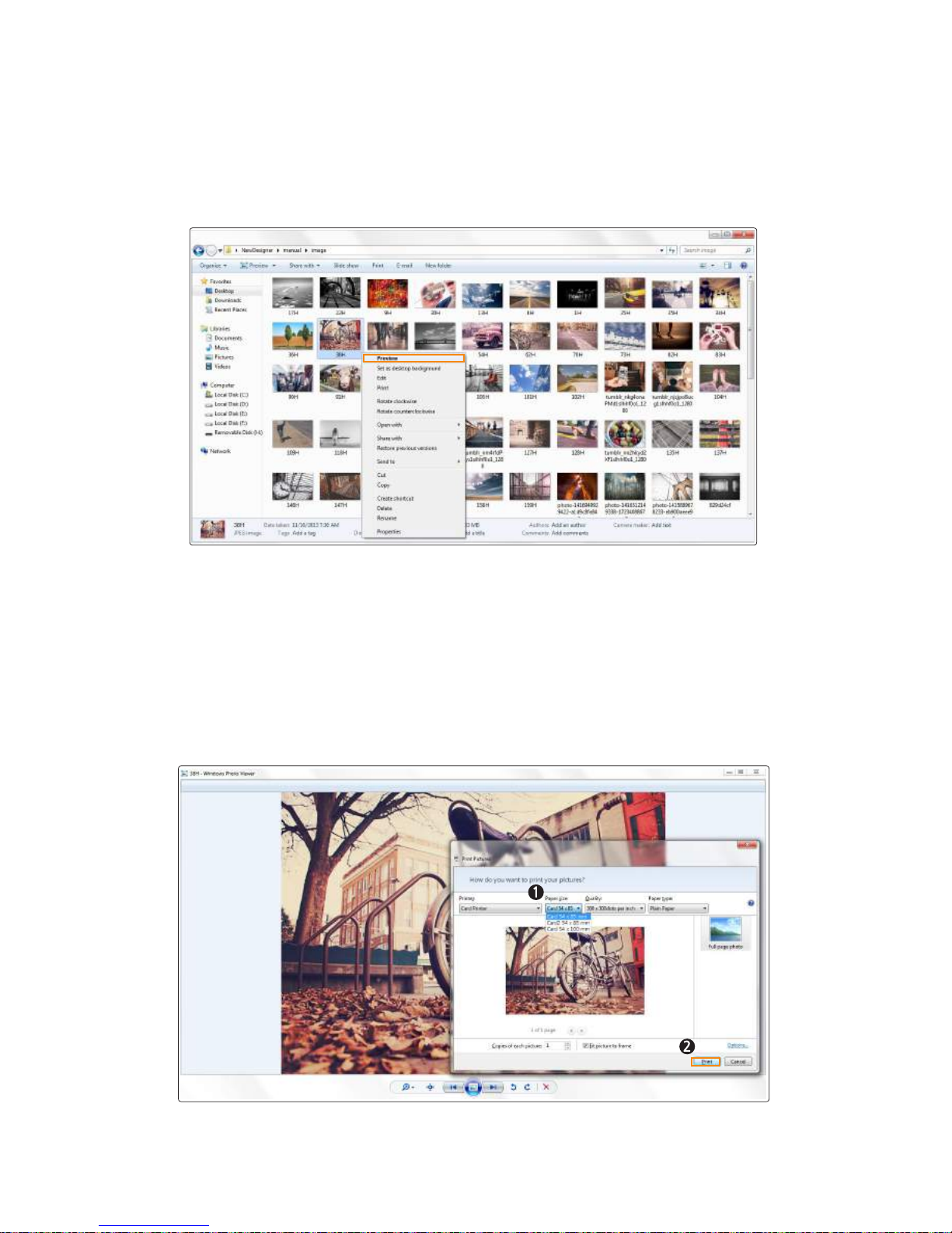
- Select Input Hopper 1/2 from External Program
(Windows Preview)
1. Right-click the image you want to print and select “Preview”.
2. Select “Print” on the Windows Photo Viewer to open the print window.
Make sure that the card printer is selected and specify the Input Hopper
using the paper size menu.
Card 54x85mm → Feed the cards from the upper Input Hopper.
Card2 54x85mm → Feed the cards from the lower Input Hopper.
After specifying the Input Hopper, click "Print" to start printing.
54
Install printer and ready
Page 55
-Print Using Application Programs
1. Specify the paper as 53.98mm x 85.60mm to print cards using application
programs e.g. Excel, Word.
2. Click “Print” in the “File” menu to open the print settings.Select “Card
Printer” in the settings and click “Print” or “OK” to print.
Make sure that the orientation of the image matches the print settings.
You can use the preview option to confirm the print output.
- You can cancel print jobs from either the application program or print spooler.
- If the card is jammed while printing, then press the "EJECT" button in the front
side of the printer.
Note
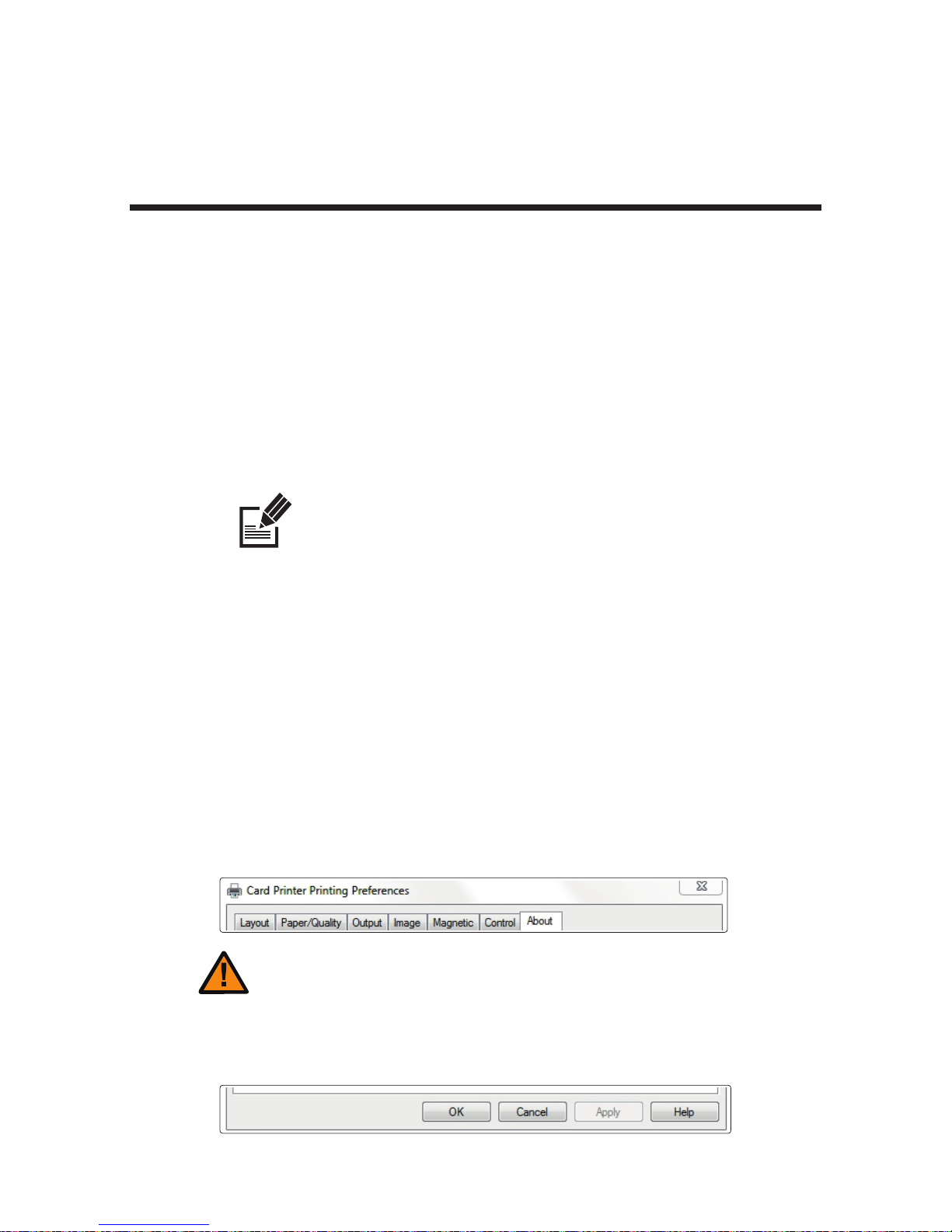
-Configure Printer Default Settings in
Application Programs
Each time you change the print settings in the application program, it will be
reset to the default settings when you exit the program.
Click “Print” in the “File” menu to open the print settings.
Go to “Printer Properties → Card Printer Printing Properties” in the printer
section and change the settings in the “Layout, Output, Image, Magnetic,
Control, and About” tabs. (Click each tab to open the settings.)
Click "OK" to complete the process.
The card printer does not use the "Paper/Quality" tab in the Card Printer
Document Properties.
Print Using Application Programs &
Configure Driver Settings
Caution
55
CIM User Guide Manual
Page 56

① Layout
Orientation Sets the card orientation (Landscape, Portrait)
Page Order
Sets the page sequence.
Page Format
Not applicable.
Item Description
56
Install printer and ready
Page 57
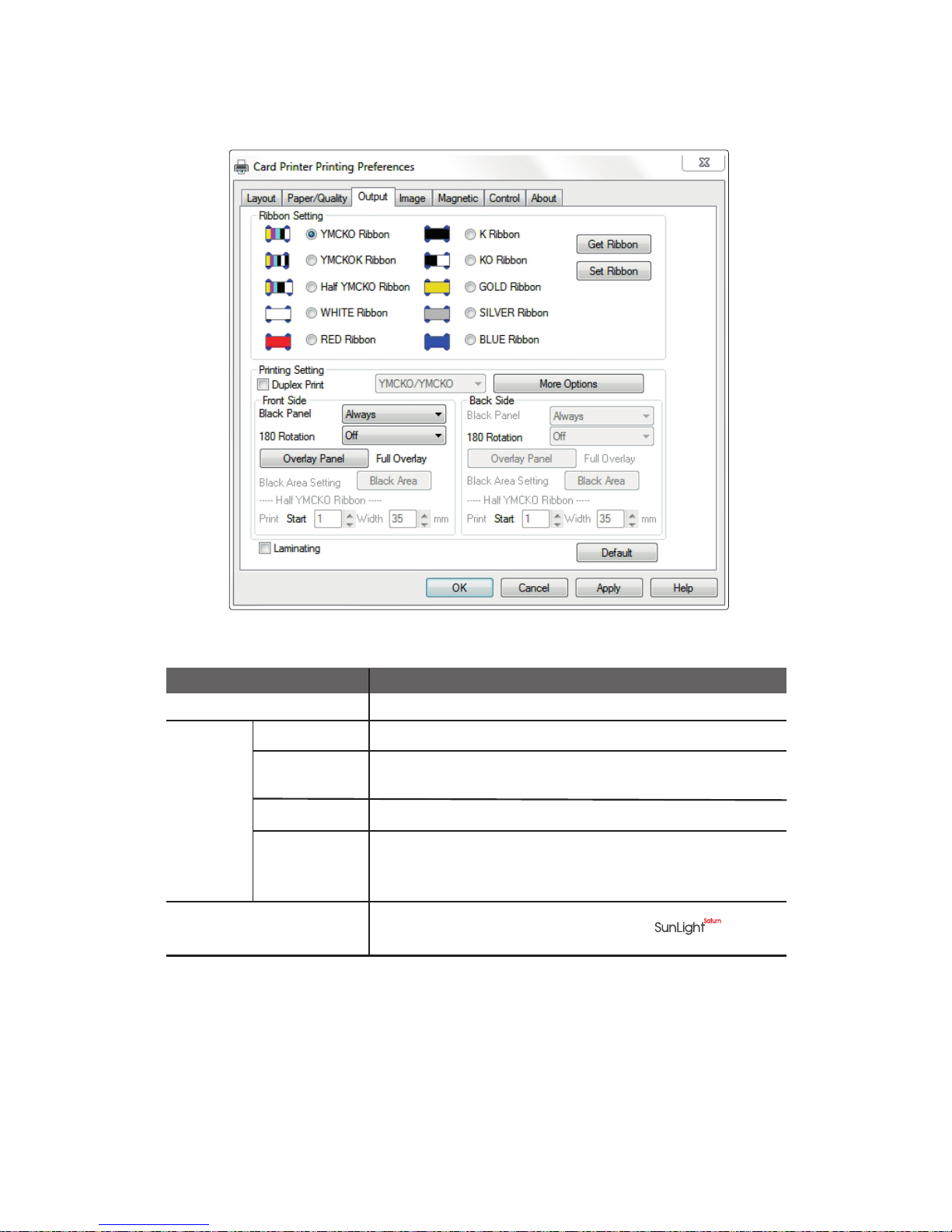
② Output
Ribbon Setting Sets the type of ribbon.
Duplex Print
Prints on both sides of the card.
Black Panel
Selects the K panel for printing black text and black & white
images included in the document.
Item Description
180 Rotation
Rotates the document 180 degrees.
Overlay Panel
Sets the type of overlay panel for protecting the printed card.
-Full Overlay /No Overlay /Selected Area /Use Image File
-Smart Card ISO /Smart Card AFNOR /Magnetic Card
Using the printer command
(TPCL) 2.0
Check the box for more stability when using
Printer
Setting
57
CIM User Guide Manual
Page 58
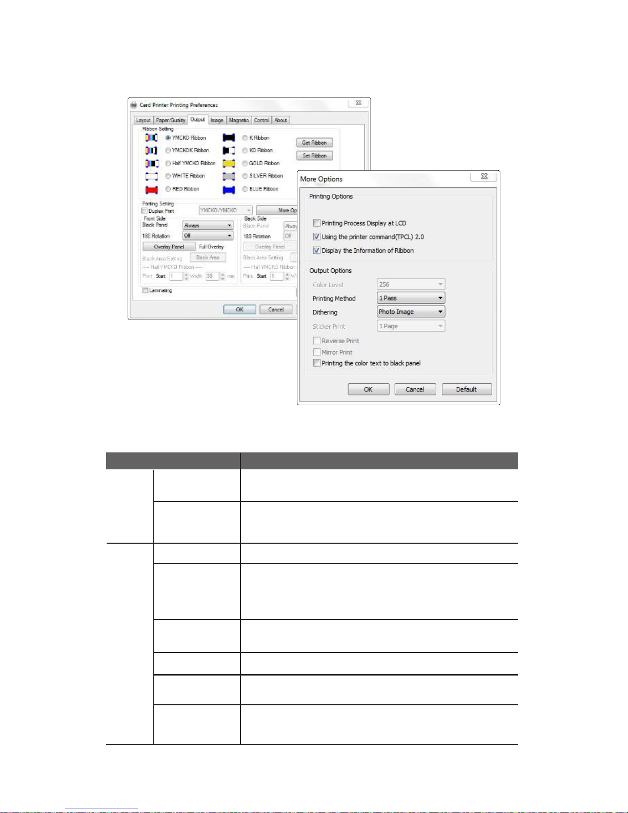
③ Output-Option
Printing Process
Display on LCD
Printing Process Display on LCD
Display the
information of
ribbon
Displays residual count of ribbons.
This information is only available for ribbons with an RFID
tag, and the value is 40 or less.
Color Level Sets the number colors used for printing.
Printing Method
Printing method on ribbon movement.
1 pass: Transmit all YMCKO data at once and print.
3 Pass: Transmit each ribbon panel data of YMCKO separately and
print the transmitted data.
Dithering only applies to the data transmitted to the black panel
of the ribbon.
Dithering
Reverse Print Reverses the document.
Mirror Print
Print a mirror image of the document (flipping the image
horizontally).
Prints any color text in black.
Printing the color
text to black
ribbon(K)
Printing
Options
Item Description
Output
Options
58
Install printer and ready
Page 59
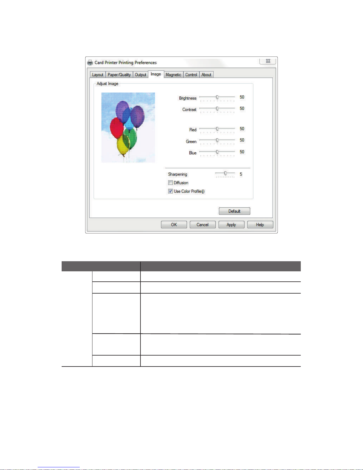
④ Image
Brightness Sets the brightness of the printed card.
Contrast
Sets dark areas as darker and bright areas as brighter.
Sharpening
Increases the contrast of adjacent pixels to make the
image look sharper..
Diffusion
Use Color Profile
This filter adjusts the contrast of the edge details and creates
brighter and darker lines on each plane of the edge, resulting
in a sharper image with clearer outlines.
Mixes the pixels of an image and makes it look blurry. This filter
mixes pixels in such a way to minimize the change of colors.
Supports more colors by using the color profile.
Adjust
Image
Item Description
59
CIM User Guide Manual
Page 60
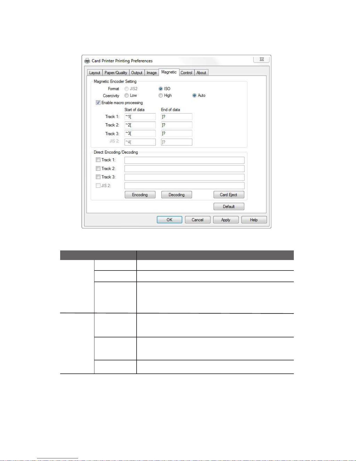
⑤ Magnetic
Format Sets the encoder format of the magnetic stripe.
Coercivity
Sets the coercivity type of magnetic stripe.
Enable macro
processing
Sends data to the magnetic stripe.
Encoding
Writes the data of selected track to the magnetic stripe.
When enabled, it detects the start and end of the encoding
data from text format and processes it with Magnetic Stripe
Encoding data.
Track 1, 2, 3: Inputs the data to write on the magnetic stripe card.
Decoding
Reads the data of the selected track from the magnetic stripe.
Track 1, 2, 3: Displays the data read from the magnetic stripe card.
Card Eject Ejects any card inside the printer.
Magnetic
Encoder
Settings
Direct
Encoding
/Decoding
Item Description
60
Install printer and ready
Page 61
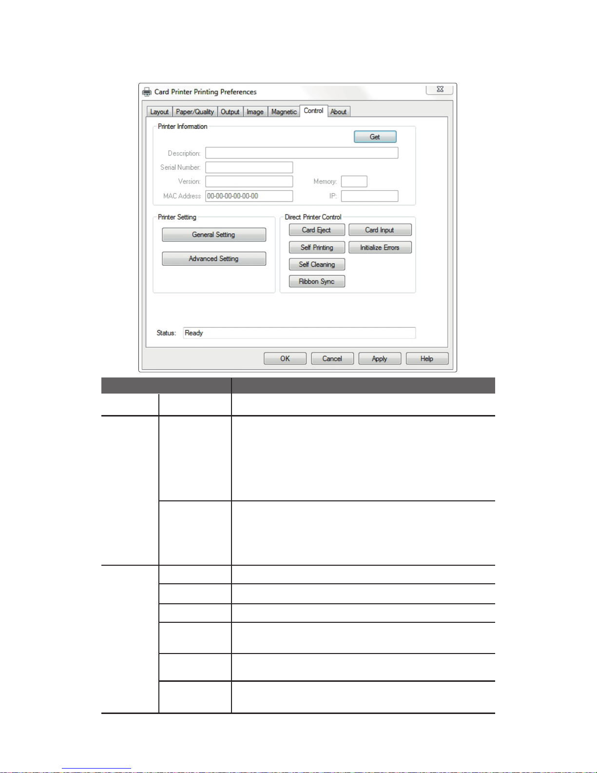
⑥ Control
Get Retrieves and displays the information from the printer.
General
Setting
Retrieves/changes the printer settings.
- Print Speed (Mono): Normal, Low
- Auto Ribbon Sync: No, Yes
- Card Ready Position: Eject, Internal
- Card Input Option: External, Internal
- Card Eject Time: 0 - 30 seconds
- Card Insert Time: 2 - 20 seconds
Advanced
Setting
Retrieves/changes the printer settings.
-TPH Resistance: 2400 ~ 3600
-TPH Model: KEE, KPE, KPE2
- Card Margin Setting: X-Start, X-End, Y-Offset
- Intensity: Color/Mono Ribbon
Card Eject Ejects the card inside the printer.
Card Input Inserts the card placed in the slot.
Self Printing Prints a self-test card.
Self Cleaning
Ribbon Sync
Synchronizes the ribbon. It performs the same function as the
“RIBBON SET” button.
Initialize Errors
Removes the error status of the printer. This does not solve any errors,
but only removes the status so it can process the next command.
Printer
Infomation
Printer
Setting
Direct
Printer
Control
Item Description
Initializes the cleaning cycle. Make sure that the cleaning
card is available.
61
CIM User Guide Manual
Page 62
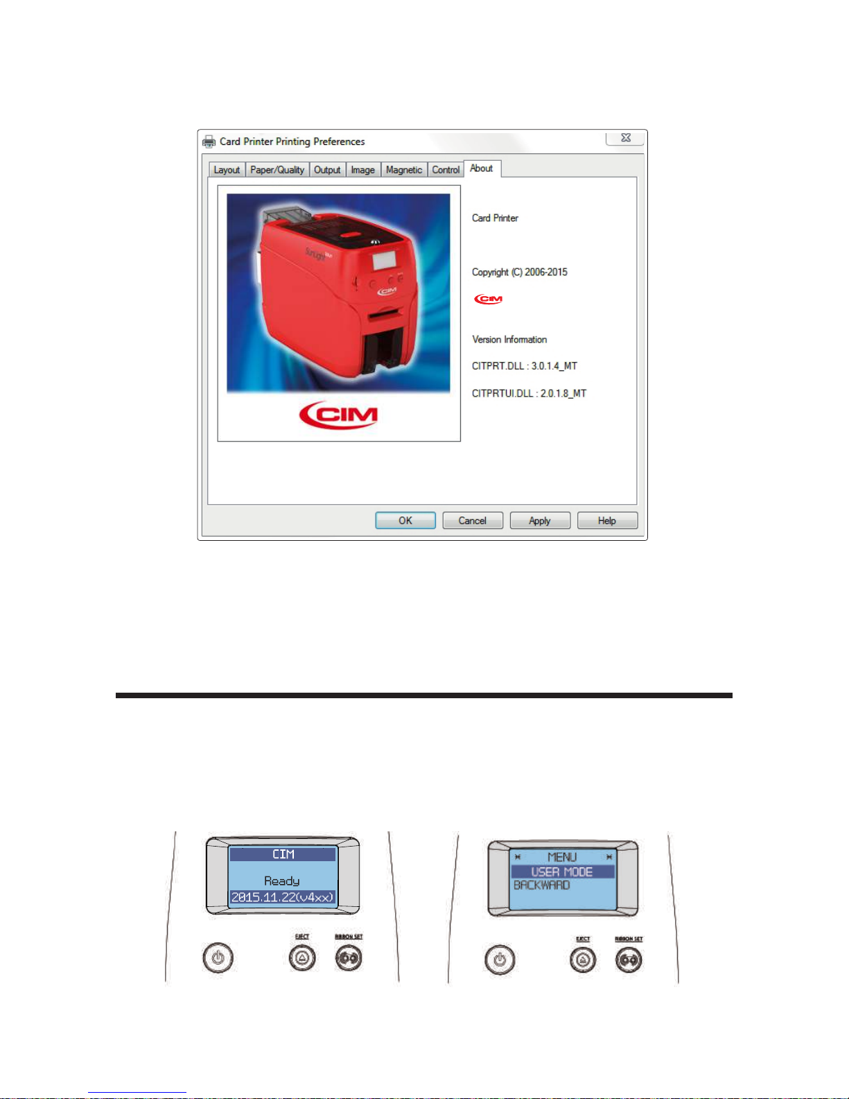
⑦ About
This tab displays the version information.
1. Hold down both the “EJECT” and “RIBBON SET” buttons until “USER MODE”
is indicated in the LCD display.
STAND-BY MODE USER MODE
-Check IP Address
Check IP Address & Print Test Card
62
Install printer and ready
Page 63
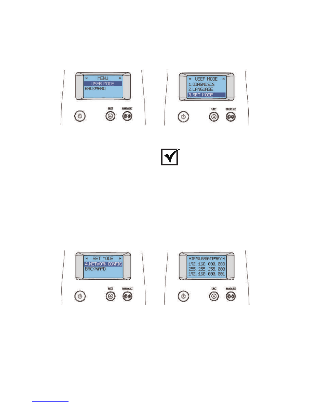
Go up the menu: Pre ss the “EJECT” button.
Go down the m e nu: Press the “RIBBON SET” button.
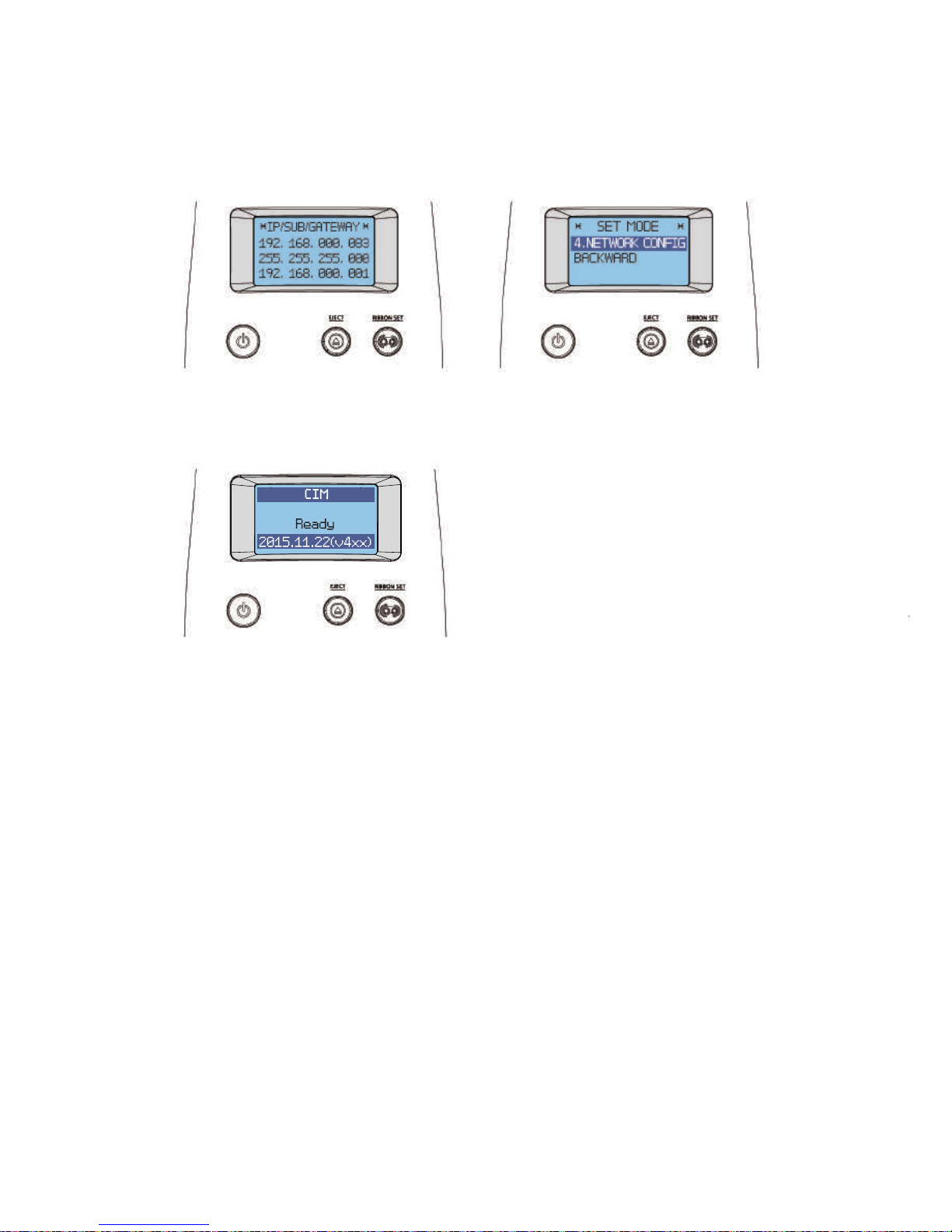
Check
3. When “SET MODE” is indicated in the LCD display, press the “RIBBON
SET” button several times to go to “4. NETWORK CONFIG”. Then, hold
down the “RIBBON SET” button until the IP address displays on the screen.
SET MODE
NETWORK CONFIG IP/SUB/GATEWAY
2. When “USER MODE” is indicated on the LCD display, press the
“RIBBON SET” button to go into “3. SET MODE”. Then, hold down
the “RIBBON SET” button.
USER MODE
63
CIM User Guide Manual
Page 64
-Print Self-Test Card
1. Turn on the printer connected to a PC.
① If Connected to a PC
2. Load the ribbon and press the “RIBBON SET” button.
3. Insert a single card into the slot or load it on the Input Hopper.
4. To go into STAND-BY mode, hold down both the “EJECT” button and
“RIBBON SET” button together to go to the previous menu (“4. NETWORK
CONFIG”). Then, hold down the “EJECT” button to enter STAND-BY mode.
4. Go to "Hardware and Sound → Devices and Printers" in the "Control Panel".
64
Install printer and ready
NETWORK CONFIG
IP/SUB/GATEWAY
STAND-BY MODE
Page 65
② If Not Connected to a PC: User Mode
1. Turn on the printer (there is no need to connect it to a PC).
2. Insert a single card into the slot or load it on the Input Hopper and load
the ribbon.
STAND-BY MODE USER MODE
3. Hold down both the “EJECT” and “RIBBON SET” buttons until “USER
MODE” is indicated on the LCD display.
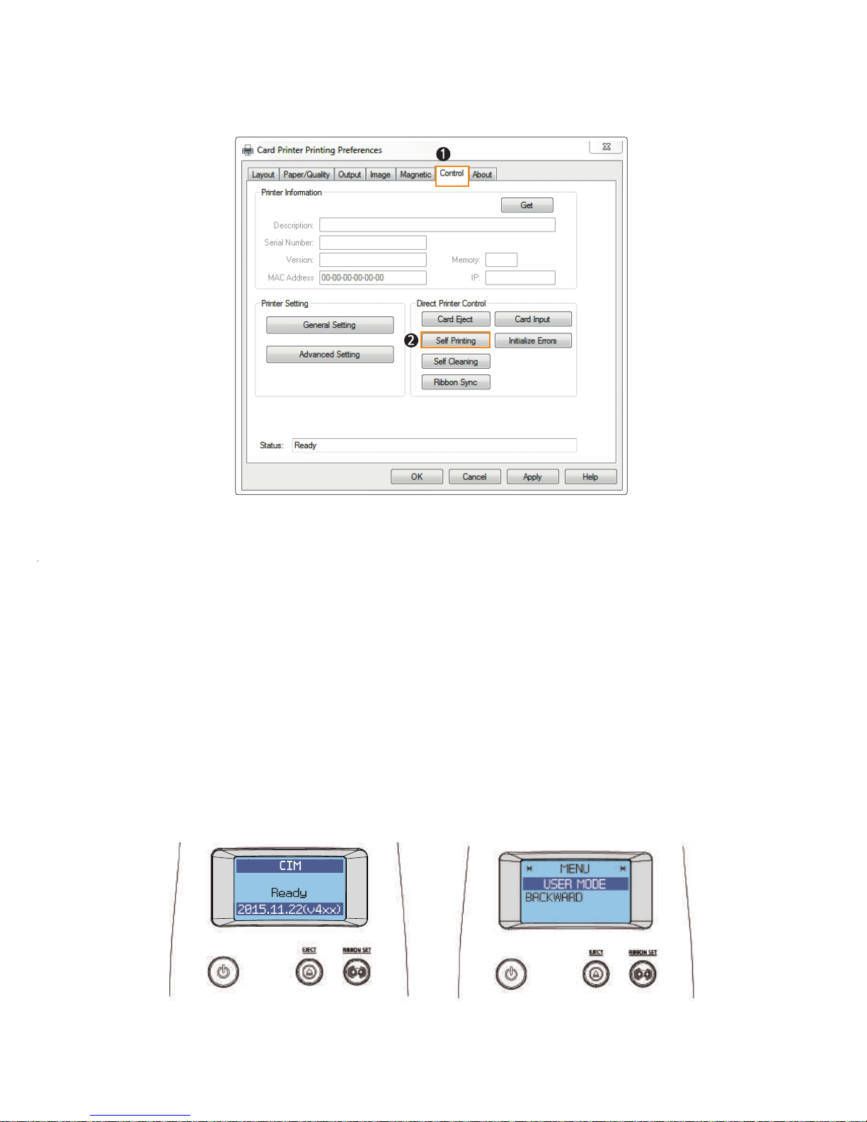
5. Select “Card Printer” and Right click → Printing preferences → Control tab
→ Direct Printer Control → Self Printing.
6. “Self Printing” is indicated on the LCD display as a test card is printed so
that you can check the printing quality.
65
CIM User Guide Manual
Page 66
DIAGNOSIS
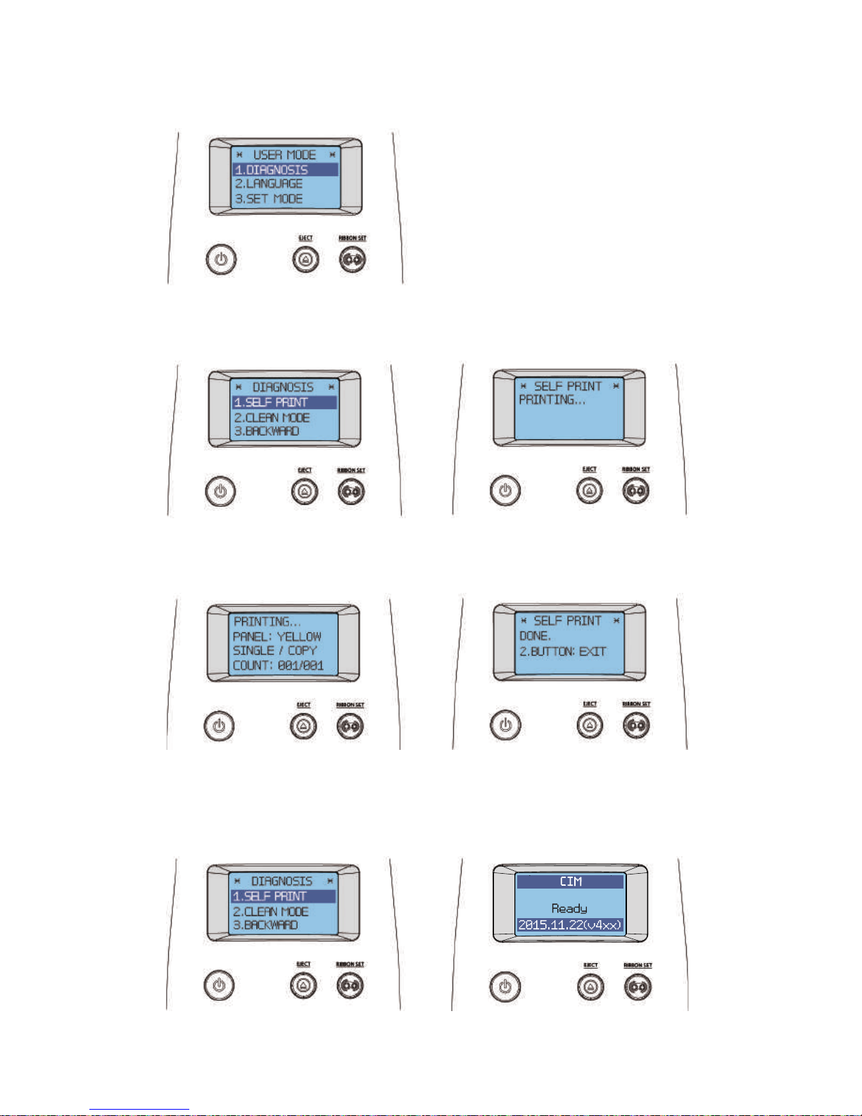
4. Hold down the “RIBBON SET” button in the USER MODE, and go
into the “1. DIAGNOSIS” menu.
5. Hold down the "RIBBON SET" button in the "DIAGNOSIS → 1. SELF
PRINT" menu to start printing a test card.
STAND-BY MODE
SELF PRINTING
SELF PRINTING MODE
6. The printing progress is indicated on the LCD display. The card will be
ejected when the printing is completed.
SELF PRINTING DONE
SELF PRINTING
7. When the "SELF PRINTING DONE" message displays, hold down both the
"EJECT" and "RIBBON SET" buttons to go back to the "DIAGNOSIS-SELF PRINT
MODE" mode. To go into STAND-BY mode, hold down the "EJECT" button.
SELF PRINTING MODE
66
Install printer and ready
Page 67
Maintenance Instructions
-Supported Cards
This card printer may not support certain types of PVC cards.
Please use the following PVC cards to prevent any issues and achieve the
highest printing quality.
- International Standard (ISO CR80-ISO7810)
- 53.98mm (W) x 85.60mm (L)/3.375”x2.215”
① Size
- Minimum: 0.4mm
- Standard: 0.76mm
- Maximum: 1.2mm
② Thickness
- Glossy white
- Free of dirt or grease
- Not contaminated
- Free of scratches or dents
- Completely flat
- Static Free
③ Acceptable Cards
- Heavily damaged
- Stained or contaminated
- Scratched
- Bent or deformed
- Embossed
④ Unacceptable Cards
Do not load or use cards considered as
unacceptable as they may damage the
parts including the head, sensor, TPH,
and roller.
Caution
- Clean the printer with a soft, damp cloth. Make sure to unplug the power
adapter before cleaning it.
- Do not allow any liquid to drip inside the printer.
- Make sure that the printer is dry before turning it on.
Do not use any liquid / gel containing a high content of alcohol or solvent to clean
the printer as it may cause discoloration or fissure on its surface.
Caution
Clean the Printer
-Clean the Exterior
67
CIM User Guide Manual
Page 68
-Clean Inside the Printer Using Cleaning Kit
Clean inside the printer using the cleaning kit every month or every 1000 cards
Make sure to follow the instructions provided below on a regular basis as dusts
or contaminants may affect the printing quality or damage the parts.
① Cleaning Kit & Use
1) CR80 Cleaning Card:
Use for cleaning the printer path, roller, and feeding roller.
2) Long-T Cleaning Card:
Use for cleaning the printer path, roller, and feeding roller.
3) Alcohol Swab:
Use for cleaning the interior case and sensor.
4) Cleaning Pen:
Use for cleaning the TPH and sensor.
② Clean the Printer Using CR80 Cleaning Card / Long-T
Cleaning Card
CR80 Cleaning Card : insert the card to the Single Card Slot.
T Cleaning Card : remove the Input Hopper and insert the card t hrough the tray.
Using the cards in any other way may cause an error.
Caution
Insert the CR80 Cleaning Card to the Single Card Slot as shown in the picture.
1) Check the Proper Use of CR80 Cleaning Card / T Cleaning Card
CR80 Cleaning Card
68
Install printer and ready
Page 69
Insert one third of the Long-T Cleaning Card to the card tray as shown in the
picture. (Make sure to remove the Input Hopper before inserting it.)
2) Not Connected to a PC: User Mode
1. Open the TOP Cover and remove the ribbon, close the cover.
2. Press the “EJECT” button located in front of the printer to eject any card
inside the Single Card Slot. For the cards in the Input Hopper, open the
cover to remove them.
STAND-BY MODE USER MODE
3. Insert the cleaning card to the feeding slot
(Single Card Slot, Input Hopper).
4. Hold down both the “EJECT” and “RIBBON SET” buttons together until
the LCD display indicates that the printer is in “USER MODE”.
Long-T Cleaning Card
69
CIM User Guide Manual
Page 70
5. Hold down the “RIBBON SET” button in the “USER MODE” to go
into “1. DIAGNOSIS”.
6. When the LCD display indicates "1. DIAGNOSIS", press the "RIBBON
SET" button to go into "2. CLEAN MODE".
CLEANING
DIAGNOSIS
7. Hold down the “RIBBON SET” button until cleaning starts. The cleaning
card will be ejected after it moves back and forth 10 times.
USER MODE
70
Install printer and ready
Page 71
8. When the LCD display indicates “CLEAN COMPLETE”, remove the
cleaning card. Then, press both the “EJECT” and “RIBBON SET” buttons
to go back to the “DIAGNOSIS” menu.
USER MODE DIAGNOSIS
9. Hold down the "EJECT" button to go into Stand-by Mode.
STAND-BY MODE
Do not use the printer for 2-3 minutes
until the alcohol solution is fully dried.
Caution
71
CIM User Guide Manual
Page 72
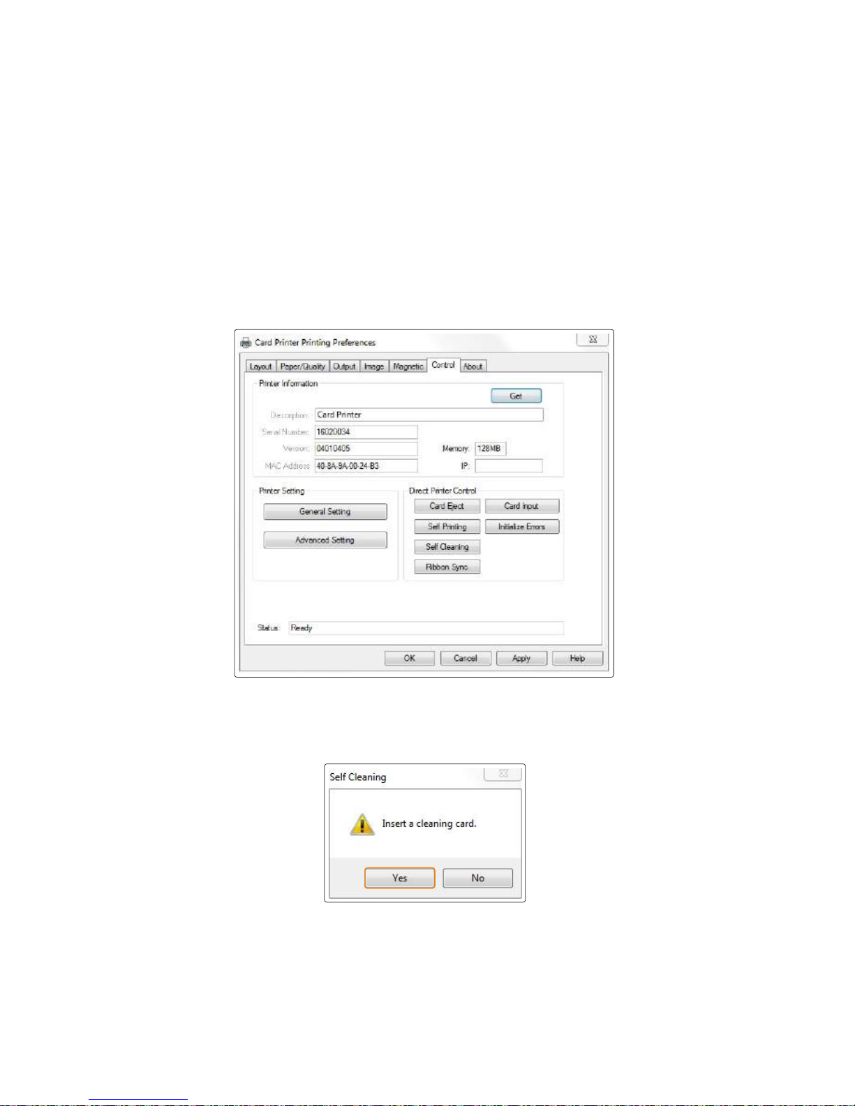
3) Connected to a PC
1. Turn off the printer and open cover, remove ribbon and all cards and close the
cover. And turn it on.
4. Insert a cleaning card when prompted by the “Insert a cleaning card”
message, and then click “Yes”.
2. Go to "Control Panel → Hardware and Sound → Devices and Printers"
and right-click the "Card Printer" driver icon. Then, select "Printing
preferences".
3. Go to “Card Printer Printing preferences → Control” and click
“Self-Cleaning”.
5. The cleaning card will be ejected after it moves back and forth 10 times.
6. Do not use the printer for 2-3 minutes until the alcohol solution is
fully dried.
72
Install printer and ready
Page 73
③ Clean the Printer Using Alcohol Swab and Cleaning Pen
Do not use any liquid / gel containing a high content of alcohol or solvent to clean
the printer as it may cause discoloration or fissure on its surface. Make sure to use
authorized alcohol swabs and cleaning pen only.
Caution
You can clean the printer's TPH and sensor and wipe the ink and dusts using
an alcohol swab and cleaning pen.
1) Clean the Inside of the Printer Using Alcohol Swab
2. Turn off the printer connected to a PC, and unplug the power adapter.
1. Open the Top Cover and remove the ribbon. Press the “EJECT” button located
in front of the printer to eject any card inside the printer. .
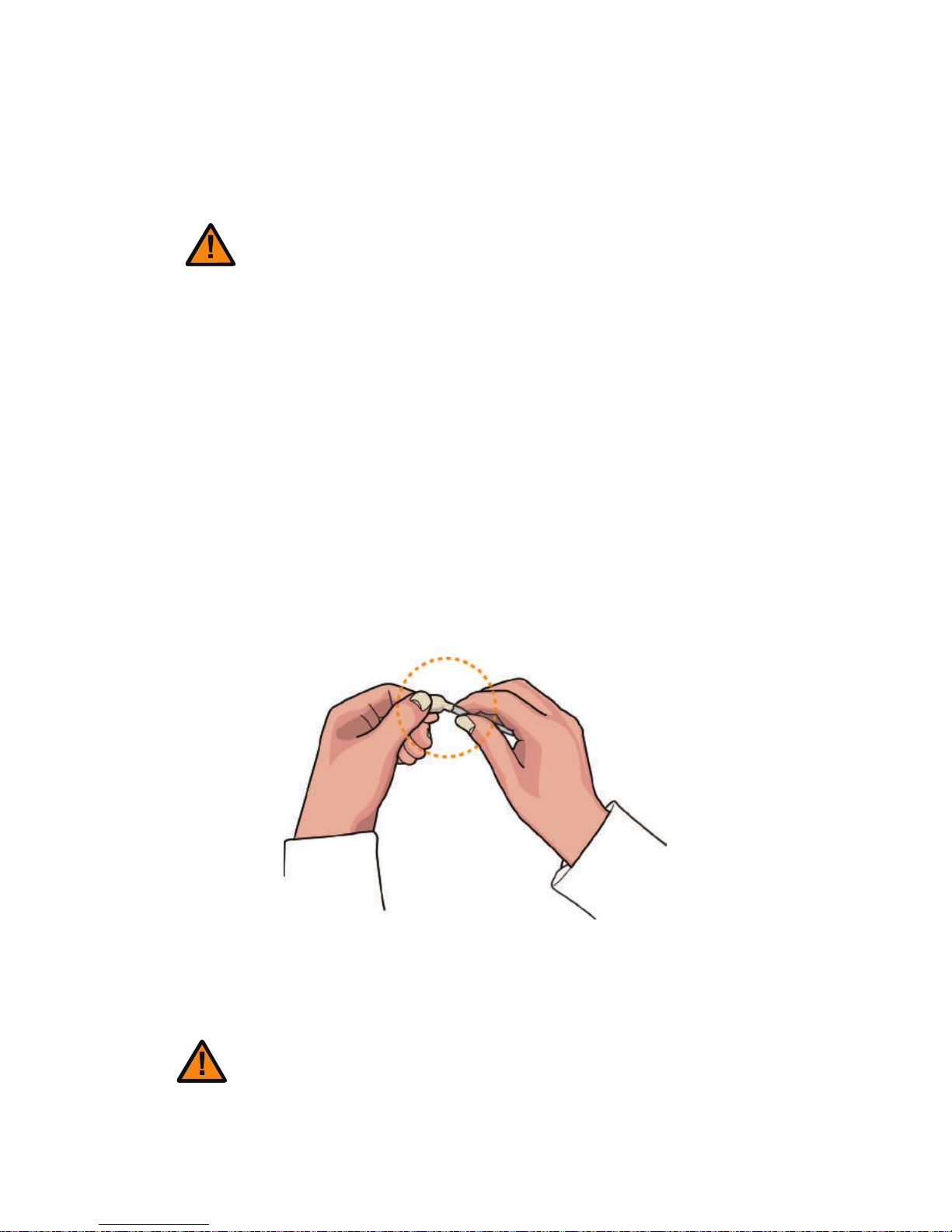
3. Take out an alcohol swab from the Cleaning Kit and fold it at the end as
shown in the picture.
4. Squeeze the transparent part until liquid comes out. Then, clean
places in the printer where you cannot reach with your hands.
Do not use the printer for 2-3 minutes
until the alcohol solution is fully dried.
Caution
73
CIM User Guide Manual
Page 74
It is recommended to clean the printer at least once a month or whenever
you replace the ribbon.
2) Clean the Printer's TPH Using Cleaning Pen and Alcohol Swab
1. Turn off the printer connected to a PC and unplug the power adapter.
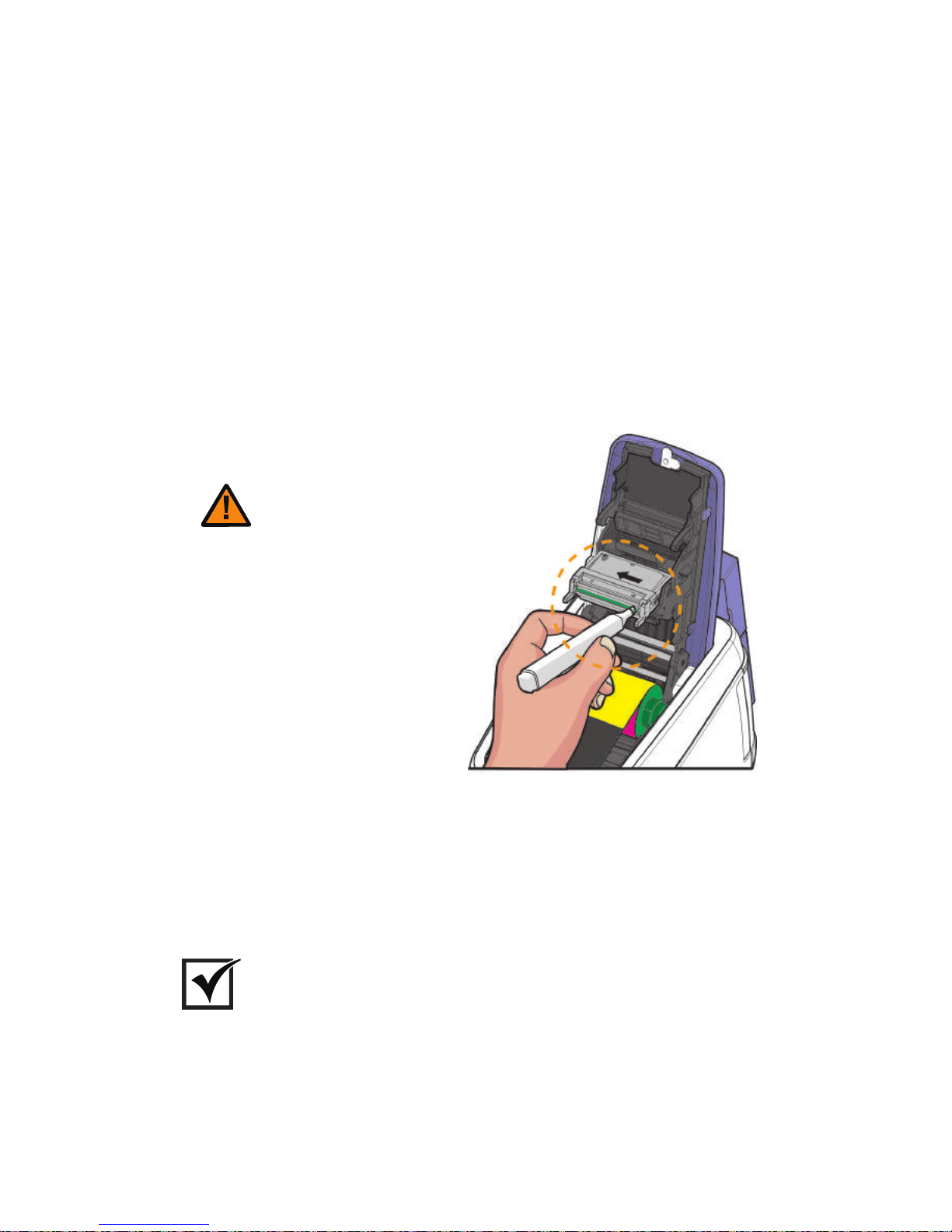
2. Clean the main body of the TPH using the cleaning pen or cotton swab
before cleaning its head.
3. Make sure to clean the ceramic edge of the printhead, as shown in the
picture.
4. Make sure that the TPH is fully dried before turning the printer on;
otherwise, the TPH may get damaged.
Do not touch the TPH head with your
hands as this can damage it.
Caution
Important
The Cleaning Pen is only included in the Advanced set sold by Cim.
74
Install printer and ready
Page 75
Some of the problems you may encounter while using the printer
can be fixed by referring to the following troubleshooting guide. If
the problem persists, then please contact your local dealer.
Code 10Code Name Description Solution
Top Cover
(TPH Module)
Check that the cover is closed
properly.
The Cover opens
while printing
11
TPH Up/Down
Failure
Check the TPH up/down module.
The TPH up/down
movement fails or is
interrupted.
13
The TPH thermistor
Temperature is
abnormal.
Check the temperature of the
TPH thermistor (operating temp.:
0c°~70c°).
Abnormal TPH
Thermistor
Temperature
Rep l ace t h e TP H.
-Errors
① TPH
Replace the TPH open checking
sensor.
-Clean the Blue Cleaning Roller
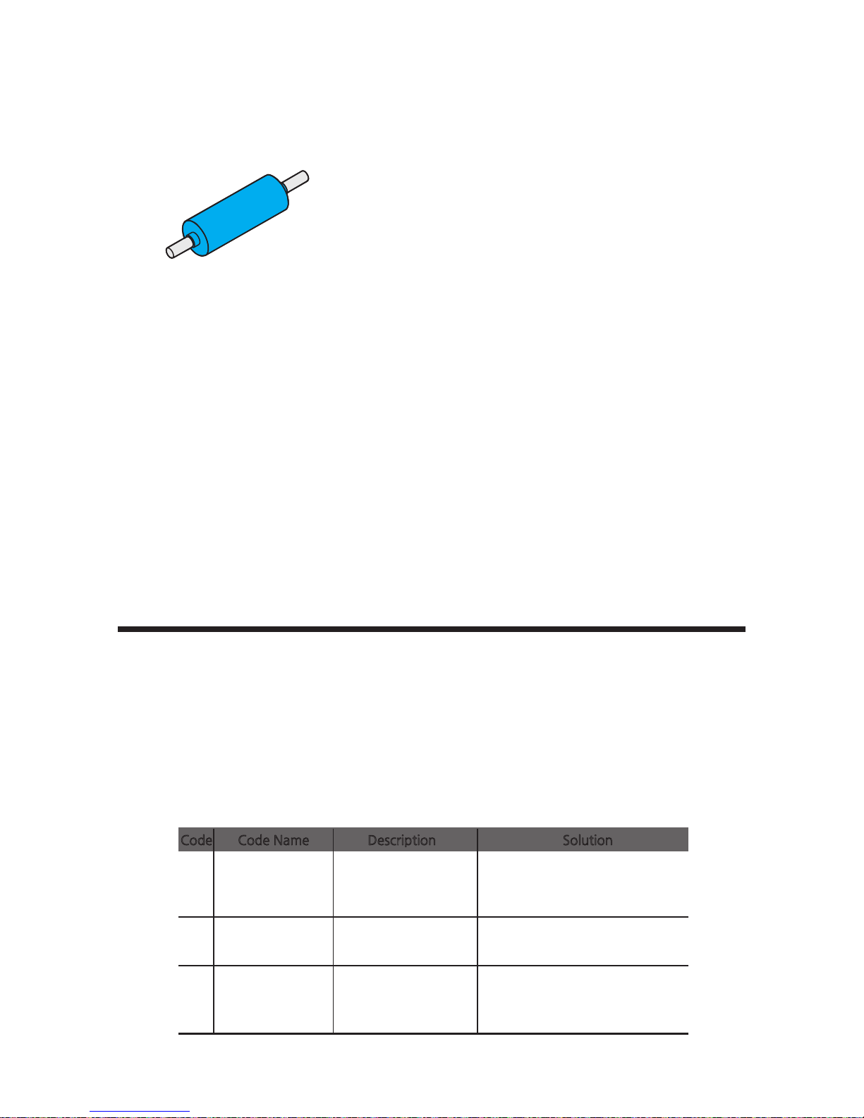
Blue Cleaning Roller
This cleaning tool is designed to remove any unwanted materials from the
surface of cards, and it can be used semi-permanently since it can be washed. It
is recommended to clean it at least once every two weeks or every 200 cards.
1. Remove the cleaning roller from the printer.
2. Wash it under running water.
3. Make sure that it is fully dried before installing it into the printer.
Troubleshooting
75
CIM User Guide Manual
Page 76
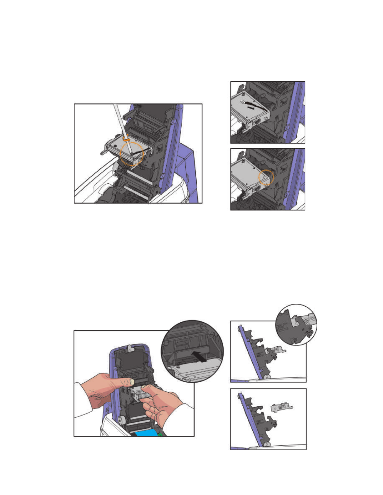
1) Replace the TPH
1. Detach the earth cable on TPH as shown in the below pictures.
2. While pressing down the black bar above printhead, push the TPH by
its body upwards and forwards. Taking care not to touch the ceramic
edge of the printhead.
76
Install printer and ready
Page 77
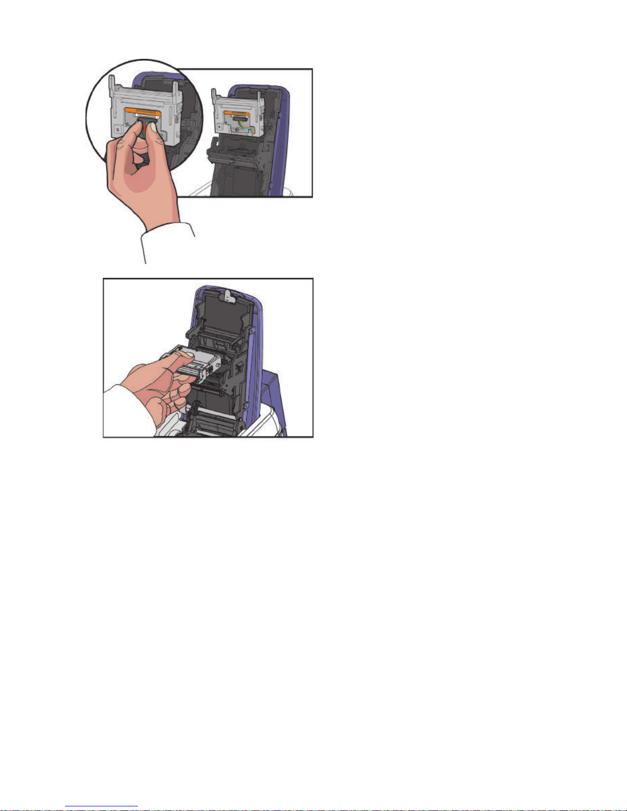
3. Remove the TPH’s connector by
lifting it.
4. Pull it towards you to remove,
and then replace it with a new one.
(Install the TPH in reverse order of
the removal steps.)
77
CIM User Guide Manual
Page 78
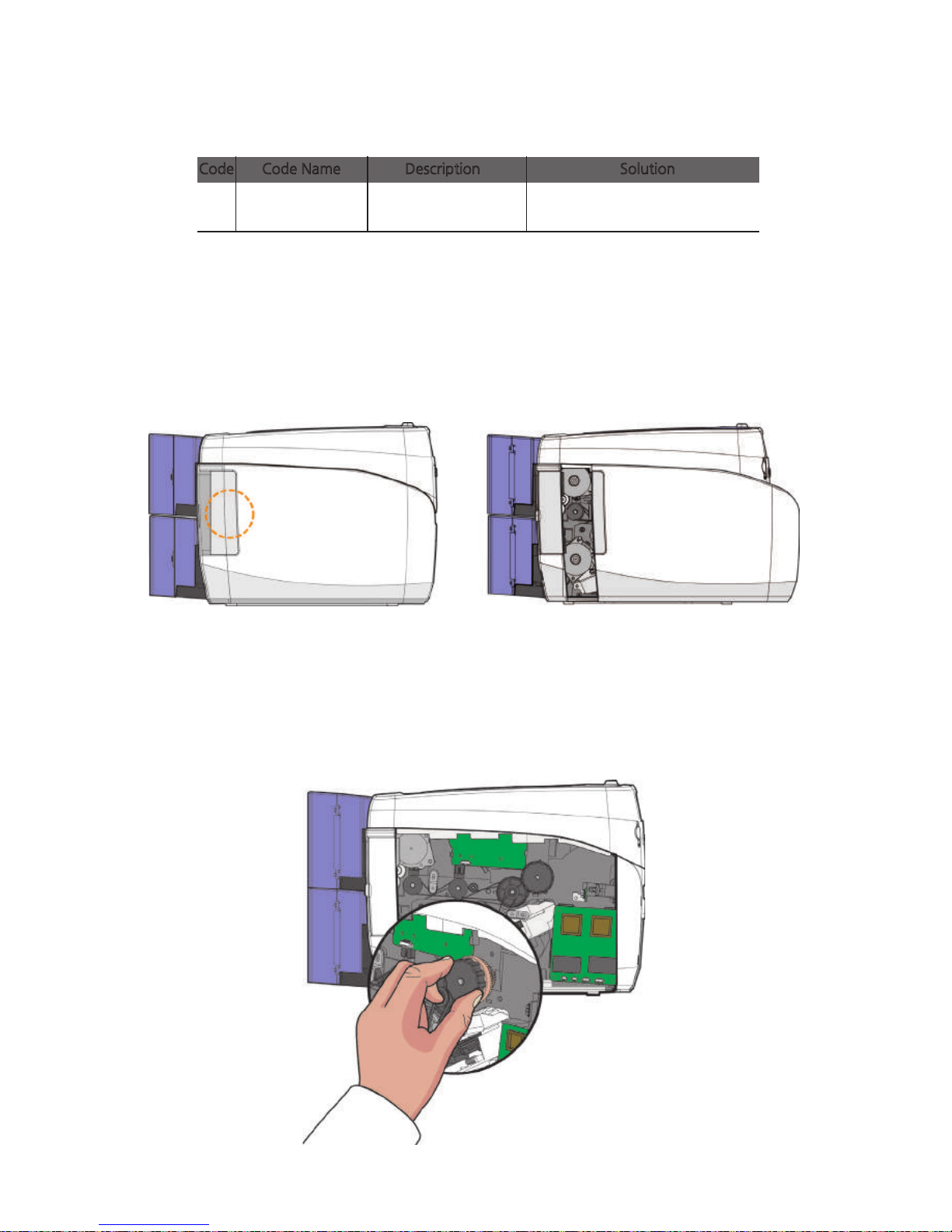
12
Card Jammed
The card is jammed in
the path.
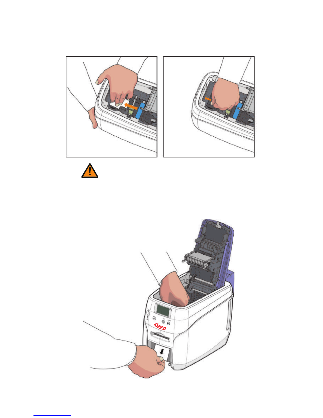
1. Open the side cover by holding the area highlighted by the circle and
pushing it towards the front of the printer as shown in the picture.
② Card Feeding
2. Rotate the knob to remove any jammed card the path as shown in the
picture.
This method can only be used for single-sided printing models (without the
flipper only.
Check the path to see if the card
is jammed.
Code Code Name Description Solution
1) Remove Jammed Card (Single-sided Printing)
78
Install printer and ready
Page 79
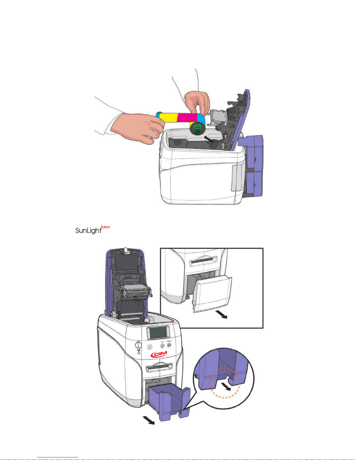
2) Remove Jammed Card (Double-sided Printing)
1. Turn off the printer and open the cover. Remove the ribbon inside.
2. Keep the cover open and remove the output card hopper(stacker).
(For , remove the front cover deco)
79
CIM User Guide Manual
Page 80
80
Install printer and ready
3. Push the card to the front of the printer and then press the card to down.
Tilt the card 70~90 degree down in order to eject the card easily.
4. Pull out the card inside manually as shown in the below pictures.
When the flipper is rotating, a card can be moved back and fort h. Hold
a card tightly in order to prevent any movement of a card.
Caution
Page 81
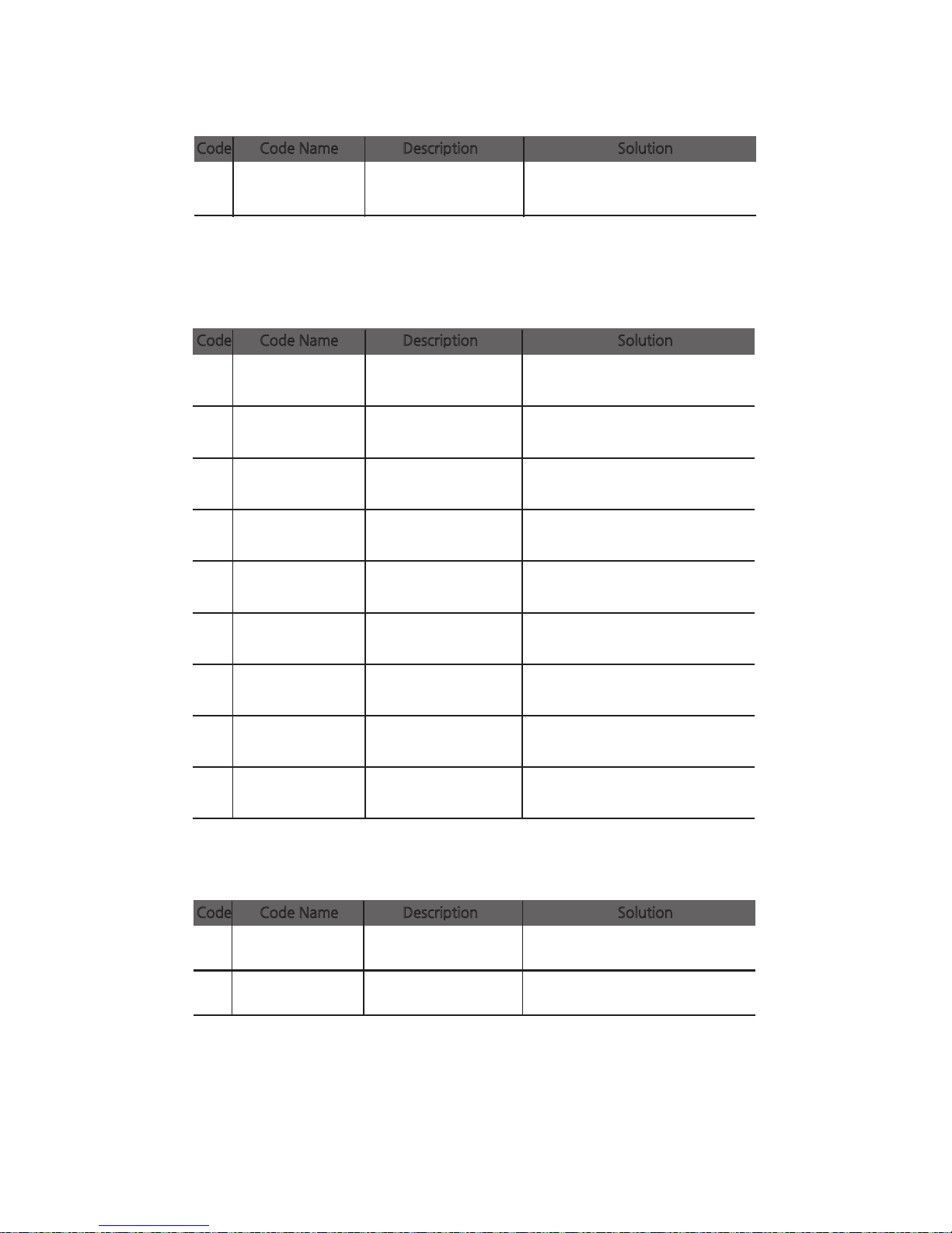
14
Ribbon Encoder
Error
Disconnected ribbon,
Ribbon end or
encoder error occurs.
17
IC Module Up/
Down Error
Repair service is required.
IC Content module
position error occurs.
50
[Changer] Module
Response Timeout
Turn off → Remove any cards →
Reboot
Flipper
communication error
occurs.
51
[Changer] Module
Transmission
Timeout
Turn off → Remove any cards →
Reboot
Flipper
communication error
occurs
52
[Changer] Home
Position Failure
Turn off → Remove any cards →
Reboot
An error occurs at the
Flipper home position.
53
[Changer] Card
Flipper Failure
An error occurs at
the Flipper turn up.
54
[Changer] Card
Input Timeout
The printer stops when
the card is entering the
Flipper.
55
[Changer] Card
Input Jam
The card fails to enter
the Flipper on time.
56
[Changer] Card
Output Jam
A card is jammed in the
Flipper.
57
[Changer] Card
Exist
An abnormal card is
found in the Flipper.
15
Media Error Check the card (media) and
path sensor status.
The media error
occurs.
16 EEPROM Error Reboot or replace the EEPROM.
An EEPROM read/
write error occurs.
③ Ribbon
④ Card
⑤ Miscellaneous
Check the Ribbon and Ribbon
encoder status.
Code Code Name Description Solution
Code Code Name Description Solution
Code Code Name Description Solution
Turn off → Remove any cards →
Reboot
Turn off → Remove any cards →
Reboot
Turn off → Remove any cards →
Reboot
Turn off → Remove any cards →
Reboot
Turn off → Remove any cards →
Reboot
81
CIM User Guide Manual
Page 82
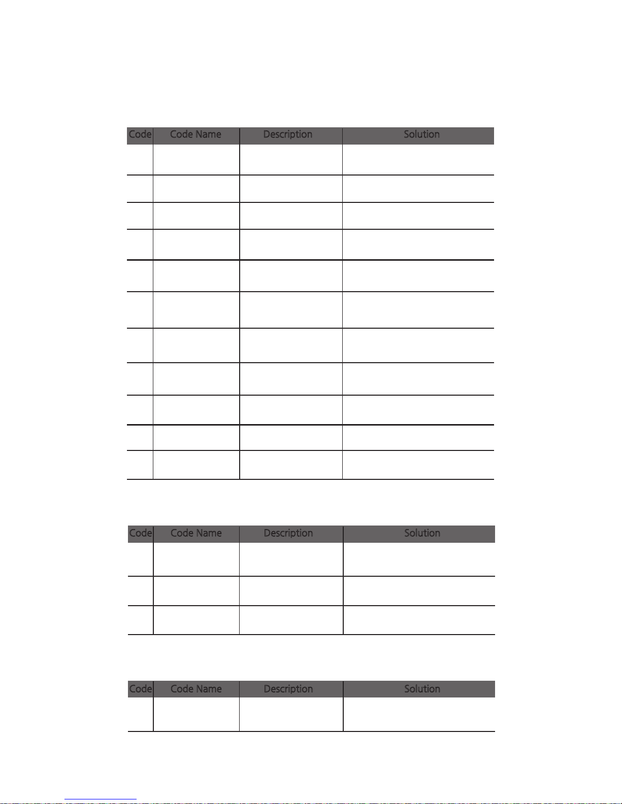
-Warning
①Card
23 [IC] Contact Error Check the IC contact module.
IC fails to make
contact.
24
[MS] Encoder
Error
Check the MS module.
An MS encoding
error occurs.
25 [MS] Read Error
All 3 MS tracks fail to
read.
Check the MS module.
26
[MS] Read STX
Error
No STX is found in the
MS reading.
Check the MS feeding.
27
[MS] Read Parity
Error
A parity error occurs
in the MS reading.
Check the MS feeding
28
[MS] Read ETX
Error
Check the MS feeding.
29
[MS] Read LRC
Error
Check the MS feeding and
replace the MS card.
30
IC Module
Response Timeout
IC module
communication fails.
Check the IFM B/D.
31 RF Module
Response Timeout
RF module
communication fails.
Check the IFM B/D.
33 Card Eject Error
Flipper module
communication fails.
Check the Flipper and Flipper
B/D.
34
Card Input
Timeout
The card input is
interrupted.
Check the Input Hopper and for
any jammed cards.
LRC is inconsistent in the
MS reading.
35
Ribbon Life Low
Prepare to replace the ribbon.
The ribbon life is
reduced to 10% or less.
② Ribbon
36
No Ribbon Life
Replace the ribbon with a new
one.
The ribbon is fully
consumed.
38
RF Tag Ribbon
Error
Check the ribbon and tag
authentication.
The ribbon is not
installed properly.
32
SAM Module
Response Timeout
Check the SAM B/D interface
and SAM B/D.
③ SAM
SAM module
communication fails.
No ETX is found in the
MS reading.
Code Code Name Description Solution
Code Code Name Description Solution
Code Code Name Description Solution
82
Install printer and ready
Page 83
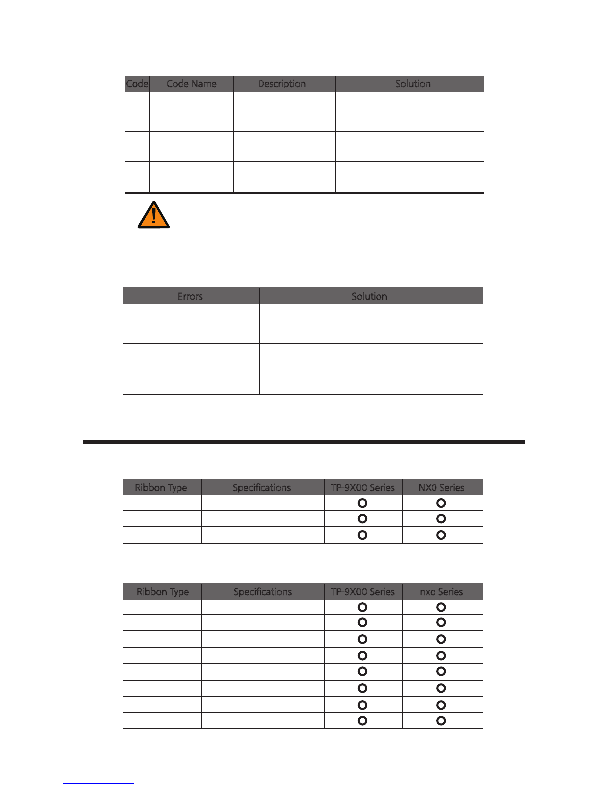
20 Command Error
Send compliant command.
The command is not
compliant with the
specifications.
21 Parameter Error
Send the parameter command.
The parameter is not
valid.
22
Main
Communication
Part Timeout
The command is not
sent on time.
Send the command.
Caution
One of the following steps must be taken to recover the printer from the error state:
1) Press the "RIBBON SET" button with the ribbon installed.
2) Press the "EJECT" button.
3) Turn off and on the power.
-Additional Errors
Errors Solution
The ribbon is frequently cut at
the top of the card.
- Check the X-coordinate in the printer driver.
- The recommended starting value for the X - coordinate
is 14 ± 2.
The printer is unable to find
the Card Designer or other
programs.
- Make sure that the printer driver is installed correctly.
- Check the connections of communication cables.
- Reboot the PC.
Ribbon Specifications
-Color Ribbons
TP-9X00 Series NX0 Series Ribbon Type Specifications
YMCKO
200 Prints/Roll
1/2YMCKO
400 Prints/Roll
YMCKO-K
167 Prints/Roll
-Monochrome Ribbons
TP-9X00 Series nxo SeriesRibbon Type Specifications
Blue
1000 Prints/Roll
Black
1000 Prints/Roll
Red
1000 Prints/Roll
Green
1000 Prints/Roll
White
1000 Prints/Roll
Metallic gold
1000 Prints/Roll
Metallic silver
1000 Prints/Roll
KO(black overlay)
500 Prints/Roll
④ Miscellaneous
Code Code Name Description Solution
83
CIM User Guide Manual
Page 84

Printer Specifications
-Product Features
2 Input Hoppers
- Load up to 200 cards with an optional Input Hopper.
- Load 2 different types of cards at the same time.
(The card type can be selected before printing.)
Compact & Light
- Only requires a small space.
- Easy to carry (4.5kg)
High Level of Security
- The ribbon and card input hopper can be locked with an optional
Kensington lock as a physical locking device (high level of security for card
printers)
Versatile Usage
- Support PCs, smartphones, tablet PCs, and other mobile devices
(Wi-Fi option is required)
-Standard Specifications
① Printing Type
- Thermal Transfer/Dye-sublimation
② Printing Function
- Single/Double-Sided, Edge-to-Edge Printing
④ Printing Speed
- Single-Sided: 180~200 cards/hr.
- Double-Sided: 100 cards/hr.
(1) Color Printing
800 cards/hr.
(2) Monochrome Printing
③ Resolution
- 300 dpi (11.8 DPM), 16.7 Million Colors
84
Install printer and ready
Page 85

⑤ Card Capacity
- Auto Feed Input: 100 standard format cards (0.76mm)
Up to 200 cards with optional input hopper.
- Auto Feed Output: 60 cards (0.76mm)
- Single Card Printing Input/Output: 1 card
-Optional Accessories
-Optional Input Hopper(increase the capacity from 100 to 200 cards)
- Automatic loader
- Ribbon Lock
-
Kensington Lock (for theft prevention of the printer)
- Wi-Fi
-Printer Specifications
① Dimensions (Width x Length x Height) & Weight
- Dimensions: 305.6mm (L) x 184mm (W) x 228mm (H)
- Weight: 3.7kg
1) Manual
Feed
- Dimensions: 366mm (L) x 184mm (W) x 228mm (H)
- Weight: 4.5kg
2) Auto Feed
② Power Adapter
- Manufacturer: CHANNEL WELL TECHNOLOGY
- Model No.: KLP-060M-VI
- Input: 100-240V ~ 50/60Hz 1.7A /Output: + 24V 2.5A 60W
Caution
Only use power adapters provided by the manufacturer;
otherwise, it may affect the printing quality.
③ Font
- MS Windows Type Fonts
85
CIM User Guide Manual
Page 86
④ Memory
- 128 MB RAM
⑤ Interface
- USB 2.0 (High-Speed), RS-232 (Only Debugging), Built in 10/100 Ethernet
⑥ PC Specifications
⑦ Software
- Card Designer
- Windows 2000, Windows XP (32/64bit), Windows Vista (32/64bit),
Windows 7 (32/64bit), Windows 8 (32/64bit), Windows 10 (32/64bit),
Windows 2012 R2 Server, Windows 2008 Server, Windows 2003 Server (32/64bit)
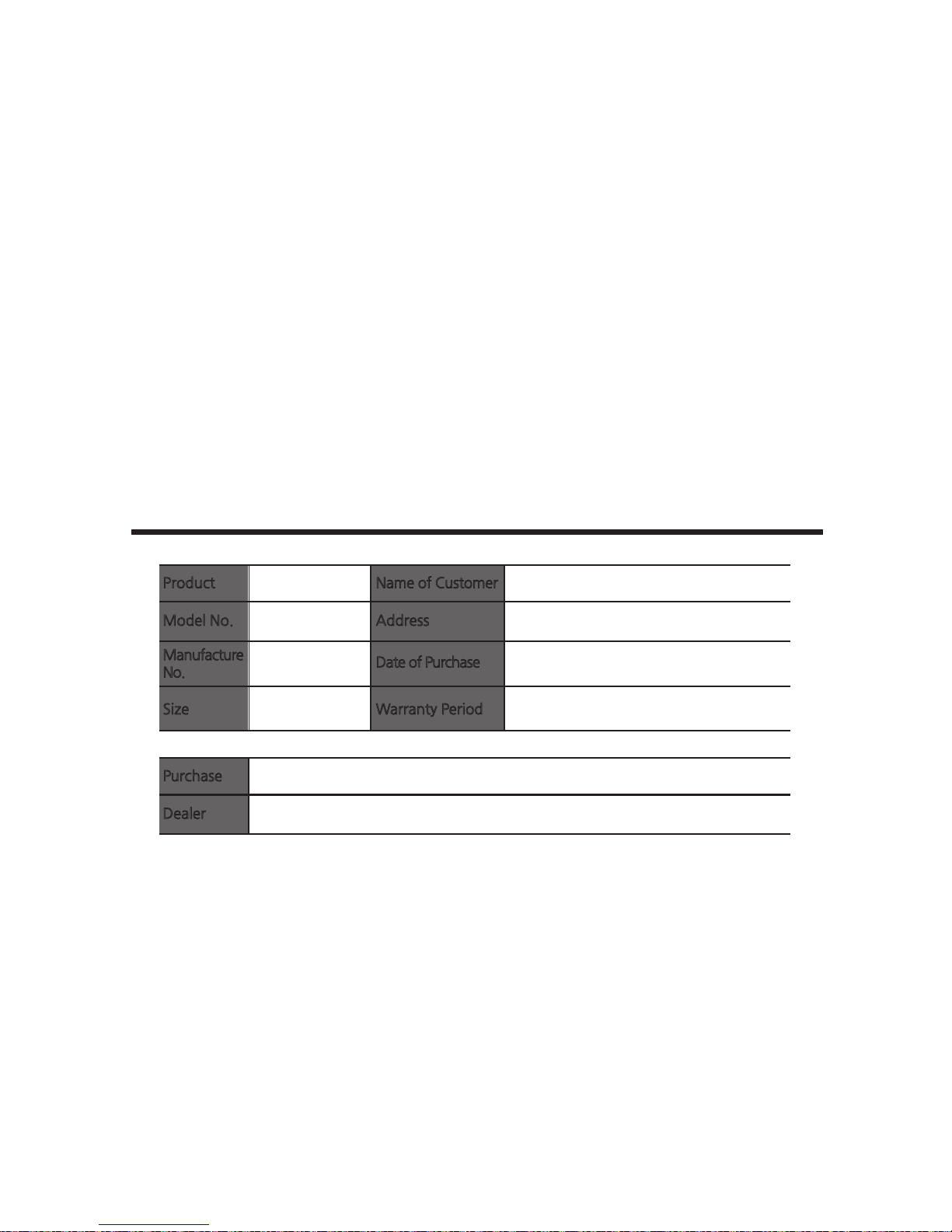
Warranty Certificate
(30 months) from the date of purchase
Product
Model No.
Manufacture
No.
Size
Name of Customer
Address
Date of Purchase
Warranty Period
(YYYY/MM/DD)
Purchase
Dealer
Address: TEL)
-Repaired at cost if any of the following apply.
- The warranty has expired.
- The product is damaged by the negligence or misuse of the consumer
(e.g. impact, water, fire).
- The product is damaged by a natural disaster (e.g. earthquake, flood).
- The product is damaged from unauthorized repair or modification.
- Consumable parts are consumed (according to the company policy).
- The product is damaged by the use of unsupported cards.
86
Install printer and ready
Page 87

87
CIM User Guide Manual
Page 88

MF GROUP srl - CIM
Via O. Serra, 2
40012 Lippo di Calderara di Reno (BO) - Italy
T. +39 051 6465 011
F. +39 051 6465 012
[email protected] - www.cimitaly.it
CIM TRADING (Shanghai) Co., Ltd
Room 506-507, Building 7,
No. 381 Panyu Road - Changning District
200052 Shanghai - P.R. China,
T. +86-21-32560811
F. +86-21-32560883
[email protected] - www.cimchina.com
CIM USA inc. - Americas
10813 N.W. 30th Street, Suite 108
Miami, FL 33172 - USA
T. +1 (305) 639 3040
F. +1 (305) 639 3060
[email protected] - www.cim-usa.com
 Loading...