

Page 1
INSTRUCTION MANUAL
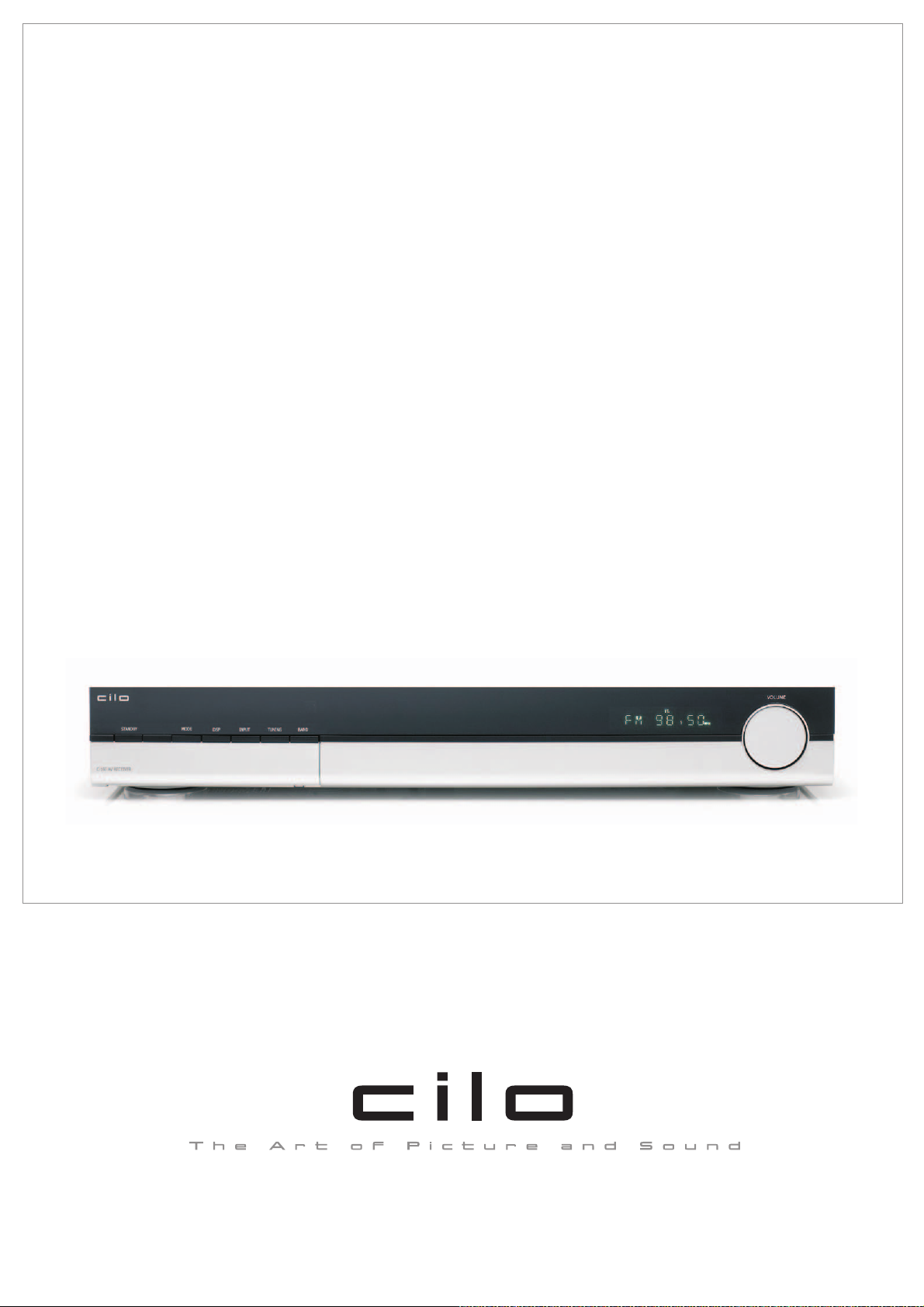
Cilo C-102 AV-Receiver
Page 2

02
Page 3

Tableofcontents
TABLE OF CONTENTS
Table of contents 03
IMPORTANT INSTRUCTIONS
Important safety instructions 04
REMOTE CONTROL
Installation of batteries 05
Using the remote control 05
Remote control functions 05
FRONT PANEL AND CONNECTIONS
Front panel 07
Connections 07
SYSTEM SETUP
Outline of audio-video connections 08
Connection through SCART cable 08
Connection through analogue audio/video cable 09
Connection through digital audio/video cable 10
Connection of loudspeakers 10
Loudspeaker arrangement 11
Installation of AM antenna 12
Connection of AM antenna 12
Installation and connection of FM indoorantenna 13
FM cable connection 13
Connection to the mains supply 14
OPERATION AND FUNCTIONS
STANDBY 15
Selection of input source 15
Loudspeaker setup 16
DSP, Mode, Mute and Bass Boost 16
Selection of input signal 17
Use of radio (tuner) 17
Manual and automatic tuning 18
Storing of radio stations 18
Selection of station and RDS 18
Selection of digital optical/coaxial inputs 19
Selection of analogue AUX 1 / AUX 2 inputs 19
TV selection 19
TECHNICAL DATA
Technical data 20
Batteries 20
TROUBLESHOOTING
Troubleshooting 21
03
Page 4
Important safety instructions
Congratulations on your new AV receiver. Please read this manual carefully to avoid malfunction and damage to the
receiver and to ensure that the receiver will be a source of great pleasure to you for a very long time.
Important safety instructions
1. Do not expose the receiver to direct sunlight,
high humidity, dirt, heavy vibration or extreme
temperatures.
2. Place the unit on a solid and plane surface.
3. Make sure that there is sufficient ventilation
around the receiver. Do not place the unit on a
soft surface such as a carpet. Make sure that
there is a clearance of 20 cm behind the unit.
4. Do not open the cabinet. Only qualified
technicians are allowed clean the internal parts.
5. Make sure that liquid and foreign matter cannot
penetrate the unit.
6. If service or repair is required, this must be
carried out by qualified technicians.
7. Unplug the unit in the following cases:
A.The mains plug or the mains cable is
defective.
B.Foreign matter or liquid has penetrated the
receiver.
C. The unit cannot be operated properly.
D.The unit has fallen down or the cabinet has
been damaged.
8. Store this instruction manual carefully for future
reference.
9. Use a duster or a slightly damp, soft and nonfluffy rag to clean the receiver.
10. Do not use corrosive or strong cleaning agents.
Make sure that no moisture penetrates the
receiver during cleaning. Unplug the unit before
cleaning.
11. The fuse of the unit is accessible to the user but
shall only be replaced by qualified technicians if
required.
12. Check that the mains voltage indicated on the
back of the receiver corresponds to the mains
voltage that the unit is connected to.
13. Read the instructions under "Troubleshooting"
before handing in the receiver for repair.
14. Unplug the unit if the receiver is not to be used
for a long time.
Disclaimer
Despite extensive efforts we cannot guarantee that
the technical data indicated are correct, complete
and updated. We reserve the right to make
technical changes without notice.
Please read these safety instructions carefully before you start using the receiver!
04
Page 5
Installation of batteries
Remote control
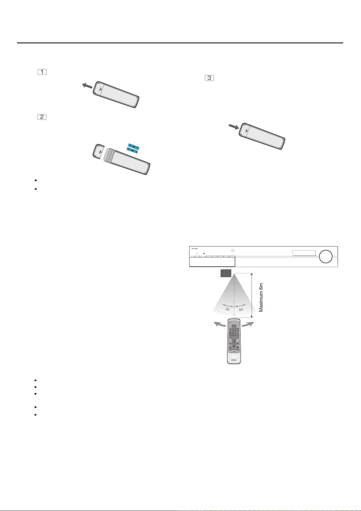
Remove the cover as illustrated.
Replace the cover.
Insert two batteries of the type
AAA/R03/UM4. Make sure that the
terminals correspond to the symbols
shown (see bottom).
Do not mix new and old batteries, and do not use different types of batteries.
If the remote control is not used for prolonged periods, remove the batteries from the remote control
to prevent corrosion.
Using the remote control
Aim the remote control at the sensor on the
receiver's front panel. When the remote control
signal is received, the receiver will respond
accordingly. The remote control works within a
range of about 6m.
STANDBY
C-102HOME THEATRE RECEIVER
MODE
TUNING BANDINPUT
DSP
Infrared-
Sensor
VOLUME
STANDBY
SPEAKER
Do not expose the unit to strong sources of light. This may disable the use of the remote control.
Do not use other remote controls near the unit. This may cause a malfunction.
Do not place any objects on the remote control as the batteries may be discharged if a key is depressed
continuously.
Do not place large objects between the remote control and the receiver.
Do not place the receiver behind tinted glass. This will reduce the range of the remote control.
05
Page 6
Remote control functions
STANDBY
SPEAKER
Remote control
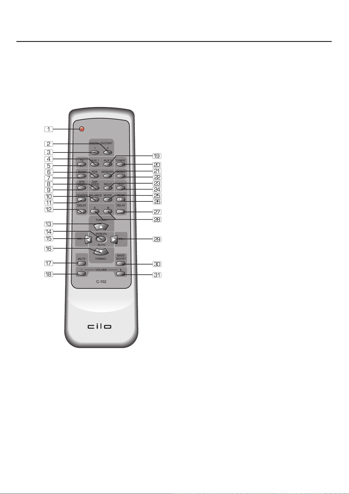
1. Standby
2. Digital Optical Input
3. Digital Coaxial Input
4. AUX 1
5. TV
6. RDS
7. Band (FM/AM)
8. DSP mode
9. SPK mode (Speaker mode)
10. Balance
11. Center delay +
12. Center delay -
13. Tuning up
14. Tuning mode
15. Preset -
16. Tuning down
17. Mute
18. Volume decrease
19. AUX 2
20. Tuner
21. Memory
22. Mono/Stereo (FM)
23. Night (Dynamic Compression)
24. Test
25. Mode [Stereo/PL II Musik/ PL II Movie,
DTS/Dolby Digital]
26. Surround delay +
27. Surround delay -
28. Speaker A/B selector
29. Preset +
30. Bass Boost
31. Volume increase
Some of the AV receiver's functions can only be performed by means of the remote control. Some functions
are connected with the signal input source selected. Some keys on the remote control thus may not be
available if the corresponding signal input source has not been selected.
06
Page 7
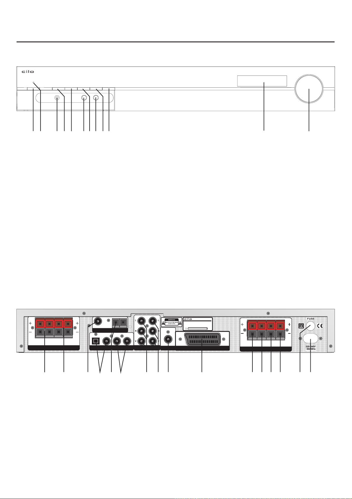
Front panel and connections
Front panel
VOLUME
STANDBY
HEADPHONE
MODE
DSP
SPEAKER A SPEAKER B
TUNING BANDINPUT
12 345 6789 1210 11
1. Standby On/Off
2. Standby LED
3. Headphone
4. Mode (Dolby Digital,
DTS, PL II Movie,
PL II Music, Stereo)
7. Input selector
8. Speaker B selector
9. Tuning
10. Band (FM/AM)
11. Display
12. Multijog
5. DSP Program
6. Speaker A selector
Connections
RL
SPEAKER A
FRONT SPEAKEROUTPUT
RL
SPEAKER B
12 3
1. Front speaker A output
2. Front speaker B output
3. FM antenna input
4. Digital input (Optical + video)
5. AM antenna input
6. Digital input (Coaxial + video)
7. AUX 1 input (Analog stereo + video)
8. AUX 2 input (Analog stereo + video)
FM - ANTENNA - AM
OPT. VIDEO COAX VIDEO AUX 1 AUX 2
5
4
6
7
AV RECEIVER
MODEL:CiloC-102
ITEMNO.: 11098.01
POWERSOURCE: 220-240V~50/60Hz
POWERCONSUMPTION: 200W MAX
SERIALNO.:
SUB SCART INPUT/OUTPUT
CEN. SW SR SL
SPEAKER OUTPUT
8 9 10 11 12 13 14 15 16
9. Subwoofer preout
10. Scart input/output
11. Center speaker output
12. Subwoofer
13. Right surround
14. Left surround
speaker output
speaker output
speaker output
15. Fuse
16. Main power
07
Page 8
System setup
SERIALNO.:
AV RECEIVER
MODEL:CiloC-102
ITEMNO.: 11098.01
POWERSOURCE: 220-240V~50/60Hz
POWERCONSUMPTION: 200W MAX
EO AUX 1 AUX 2
SUB SCART INPUT/OUTPUT
The receiver shall not be connected to the mains supply before all other system connections have been made.
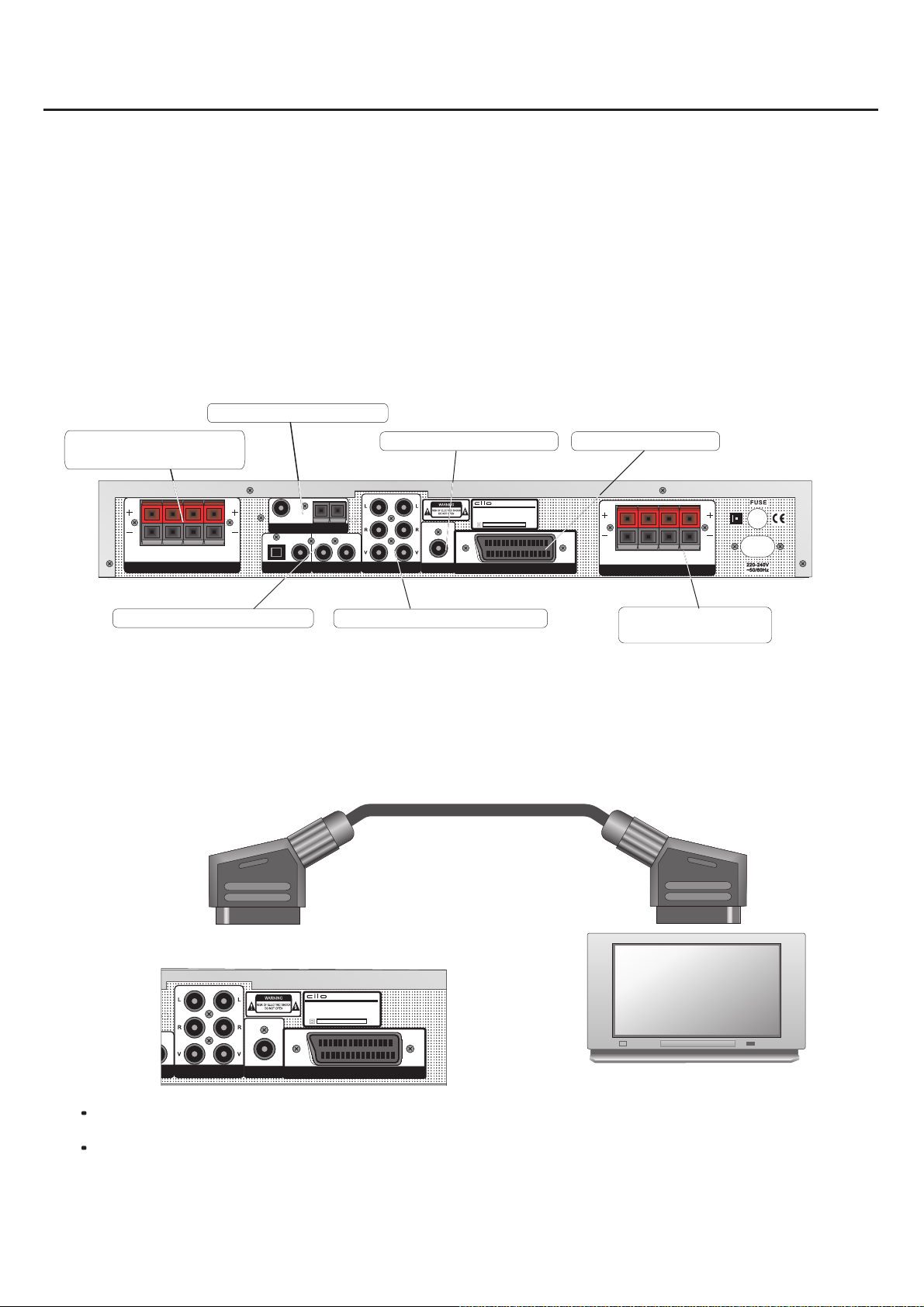
Outline of audio/video connections
The receiver is provided with two analogue and two digital audio/video inputs.
A video or digital camera may e.g. be connected through the analogue audio/video inputs.
The DVD player is connected through the digital inputs (optical or coaxial).
The video signal is transmitted to the television set through the SCART connection.
It is also possible to transmit the audio signal from the television set to the receiver through the SCART connection. This
will allow you to watch films with Dolby Surround sound if the films are coded.
FM/AM antenna input
Front speaker A & B
Active subwoofer output SCART input/output
Connections
AVRECEIVER
MODEL:Cilo C-102
ITEMNO.: 11098.01
POWERSOURCE: 220-240V~50/60Hz
POWERCONSUMPTION: 200W MAX
SERIALNO.:
CEN. SW SR SL
SPEAKER OUTPUT
Surround
RL
RL
SPEAKER A
SPEAKER B
FRONT SPEAKEROUTPUT
Digital Audio/Video in
FM-ANTENNA-AM
OPT. VIDEO COAX VIDEO AUX 1 AUX 2
Analog Audio/video input
SUB SCART INPUT/OUTPUT
Speaker connections
Connection through SCART cable
The Composite video (CVBS) and audio signals (stereo) are available at the television set's SCART output. This means
that you can use the SCART cable to quickly set up an operational system that can reproduce the television set's audio
signals through the receiver.
SCART cable
.........
.........
.........
.........
.........
.........
.........
.........
.........
.........
.........
.........
.........
.........
.........
.........
.........
.........
.........
.........
.........
.........
.........
.........
.........
.........
.........
.........
Some television sets are provided with two SCART connections! Make sure that you pick the SCART
connection marked IN/OUT! If in doubt, please read the manual provided with your television set.
Make sure that you use a fully mounted SCART cable to ensure that the receiver is fully utilised.
08
.........
.........
.........
.........
.........
.........
.........
.........
.........
.........
.........
.........
.........
.........
.........
.........
.........
.........
.........
.........
.........
.........
.........
.........
.........
.........
.........
.........
Page 9
System setup
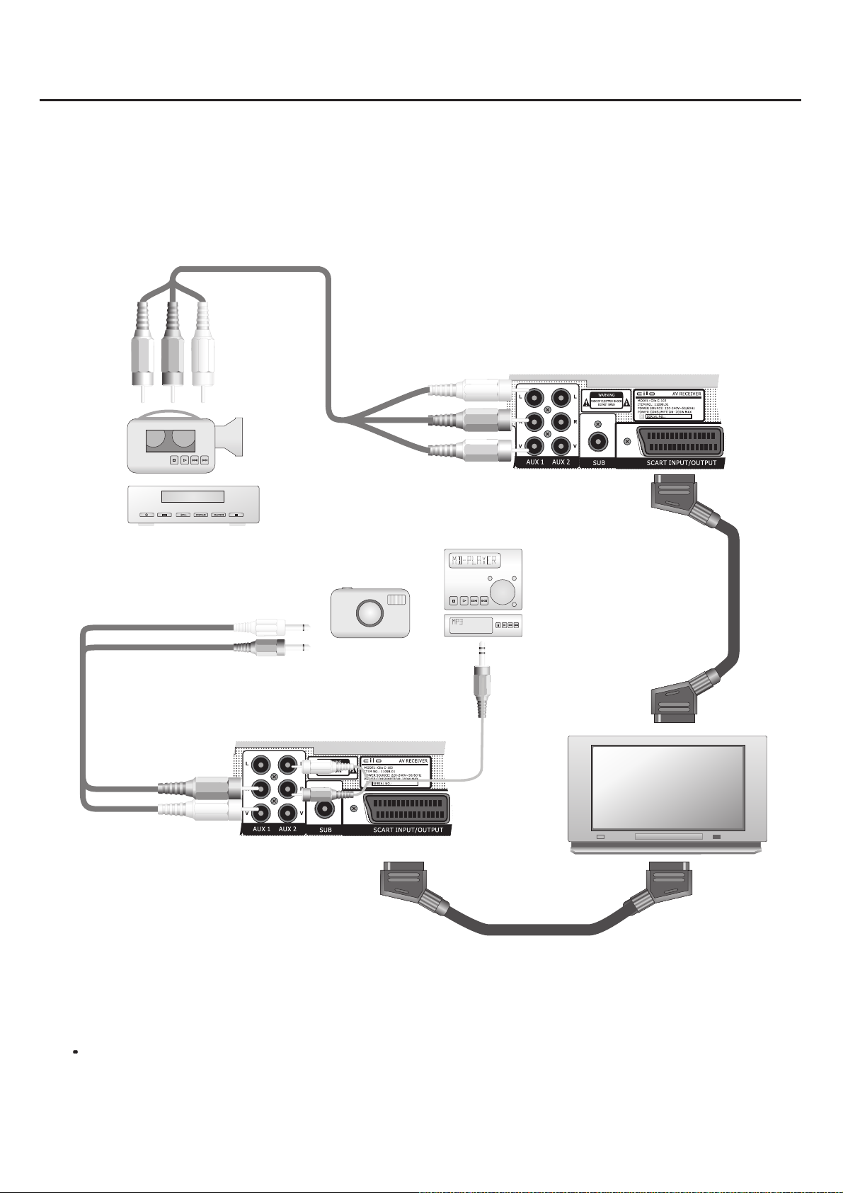
Connection through analogue audio/video cable
The audio/video jacks of the video camera are connected to the Cilo AV receiver through an audio/video cable. As you
wish to see the film through your television set, the camera must also be connected to the television set. Use the SCART
cable for this purpose (see illustration). For simplicity, the individual conductors have been marked by different colours.
3 X RCA audio video cable
Stereo camcorder
VHS
Digital Camera
Minidisc- or Mp3-player
.........
.........
.........
.........
.........
.........
.........
.........
.........
.........
.........
.........
.........
.........
.........
.........
.........
.........
.........
.........
.........
.........
.........
.........
.........
.........
.........
.........
SCART Cable
SCART Cable
.........
.........
.........
.........
.........
.........
.........
.........
.........
.........
.........
.........
.........
.........
.........
.........
.........
.........
.........
.........
.........
.........
.........
.........
.........
.........
.........
.........
The audio/video jacks of the digital camera are connected to the Cilo AV receiver through an audio/video cable. As you
wish to see the film through your television set, the camera must also be connected to the television set. Use the SCART
cable for this purpose (see illustration). For simplicity, the individual conductors have been marked by different colours.
The audio/video cables used in the illustration may deviate a little from camera to camera! If in doubt, please
read the manual provided with your video camera/digital camera.
09
Page 10
System setup
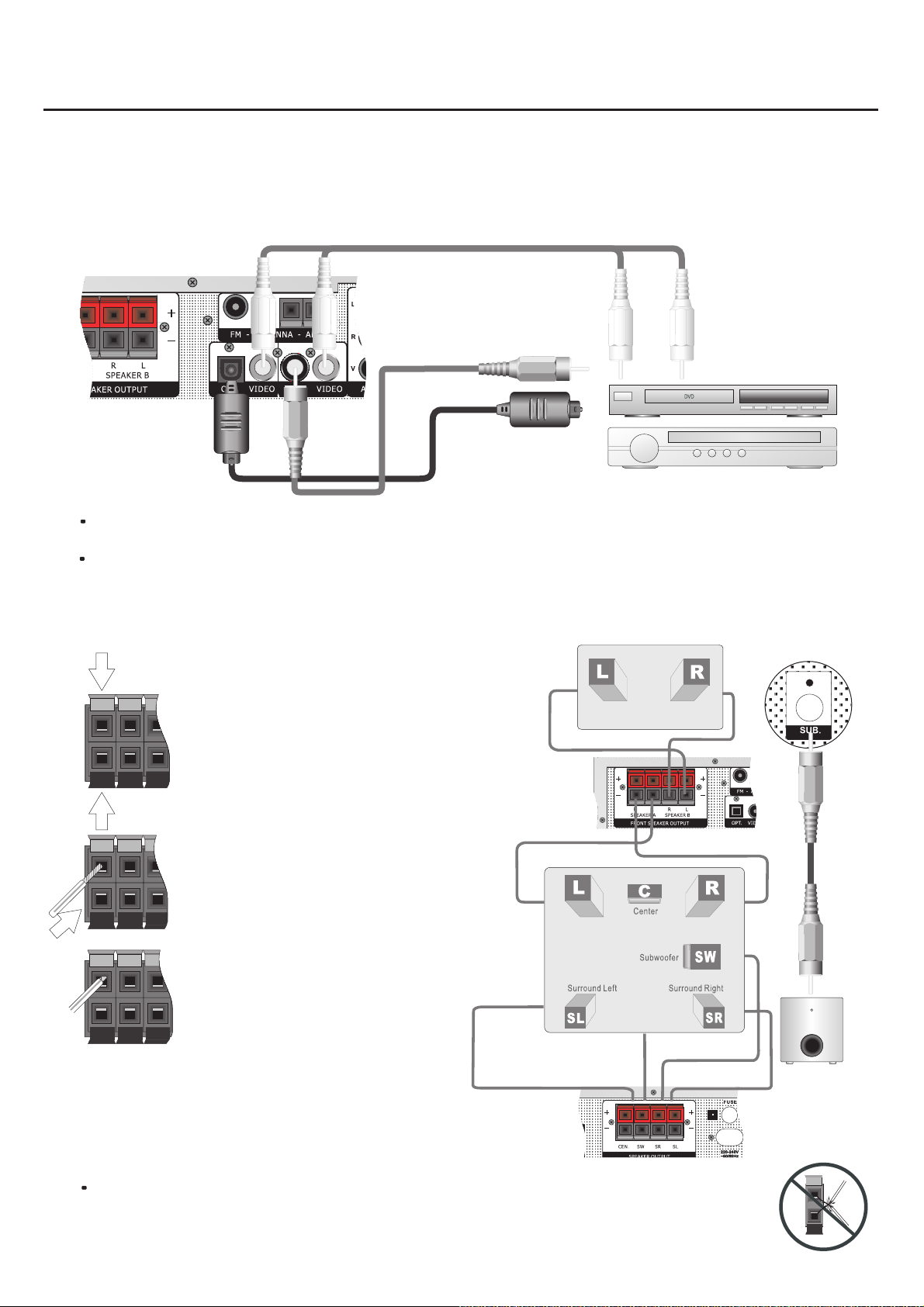
Connection through digital audio/video cable
The DVD player's coaxial or optical digital output must be connected with the corresponding digital input on
the AV receiver (OPT/COAX). Make sure always to use the corresponding video input! Switch to the
corresponding signal source by means of the INPUT key.
Video cable
Coaxial cable
Optical cable
Digital satelite receiver
Most DVD players with digital outputs are factory-set at the PCM data format.
Make sure that the DVD player has the same configuration under Setup.
The video signal may also be transmitted directly from the DVD player to the television set.
DVD-Player
Connection of loudspeakers
Remove about 15 mm of the cable
insulation.
Twist the strands carefully.
Open the terminals by pressing the
small button.
Insert the bare twisted cable ends
into the openings. Release the
button again.
Follow the same procedure to
connect the individual speaker
outputs with the corresponding
loudspeakers. Make sure that the
polarity is correct. The red terminal of
the receiver should always be
connected to the marked conductor
of the connecting cable and the black
terminal to the non-marked
conductor.
Active Subwoofer
Output
Front B RightFront B Left
Front A RightFront A Left
An active subwoofer can be connected
through Subwoofer (SUB)!
To avoid damage to electronic equipment, it must be checked that the two poles of the speaker
cable are not in contact with each other.
10
Page 11
System setup
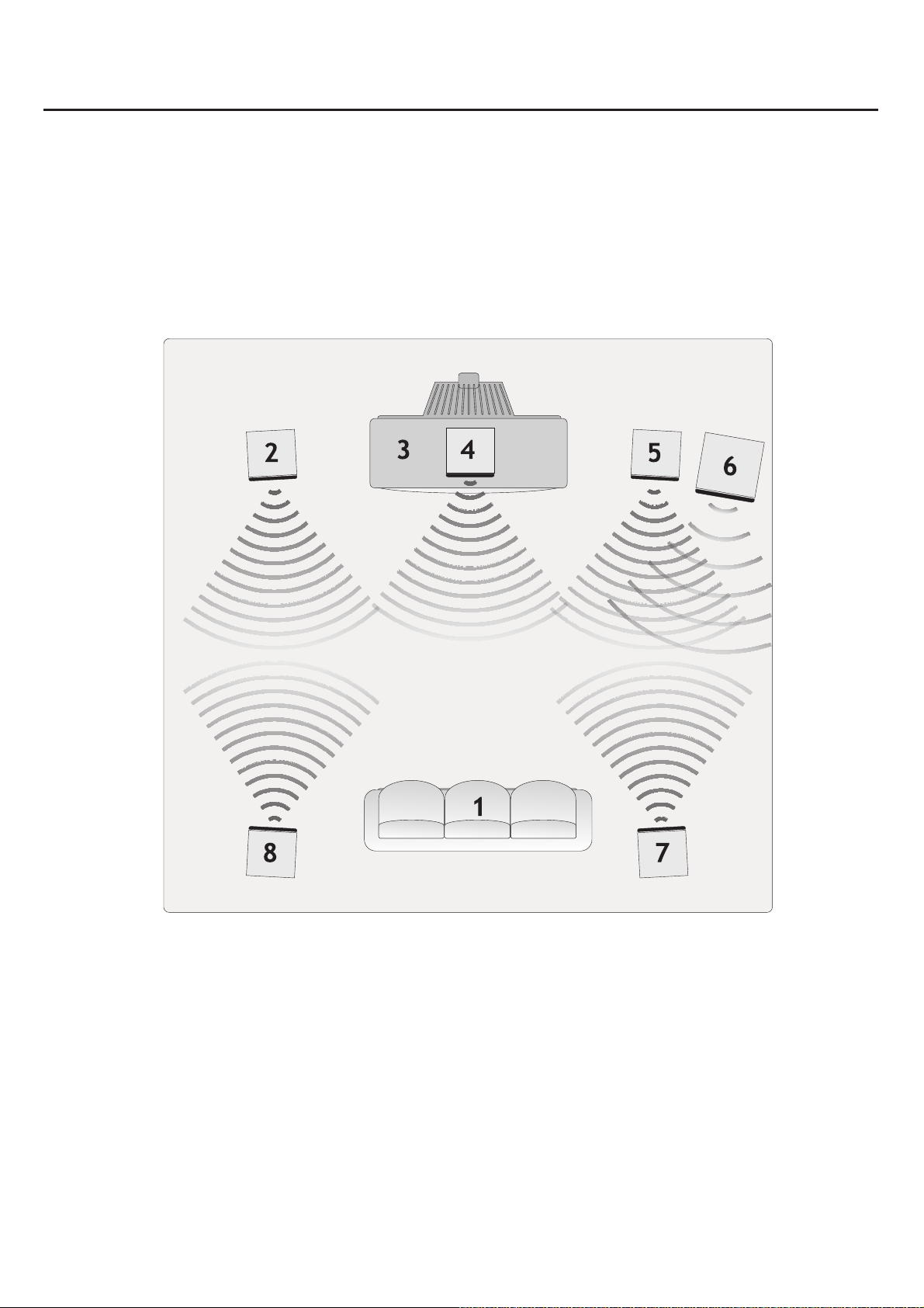
Loudspeaker arrangement
Before connecting the loudspeakers, these should be positioned correctly. Correct positioning is crucial to
ensure optimal sound. The optimal location depends on the characteristics of the room and the walls. The
illustration below shows an example of a speaker arrangement.
1. Listening position
2. Right front speaker
3. TV
4. Centre speaker
The front and centre speakers should be placed in ear height. The rear speakers should be placed a little
above ear height. The subwoofer can be placed anywhere in the room. If the subwoofer is placed in a corner
of the room, its performance will improve. The subwoofer should not be placed too close to the television set
to avoid magnetic disturbance.
5. Left front speaker
6. Subwoofer
7. Right surround speaker
8. Left surround speaker
11
Page 12
System setup
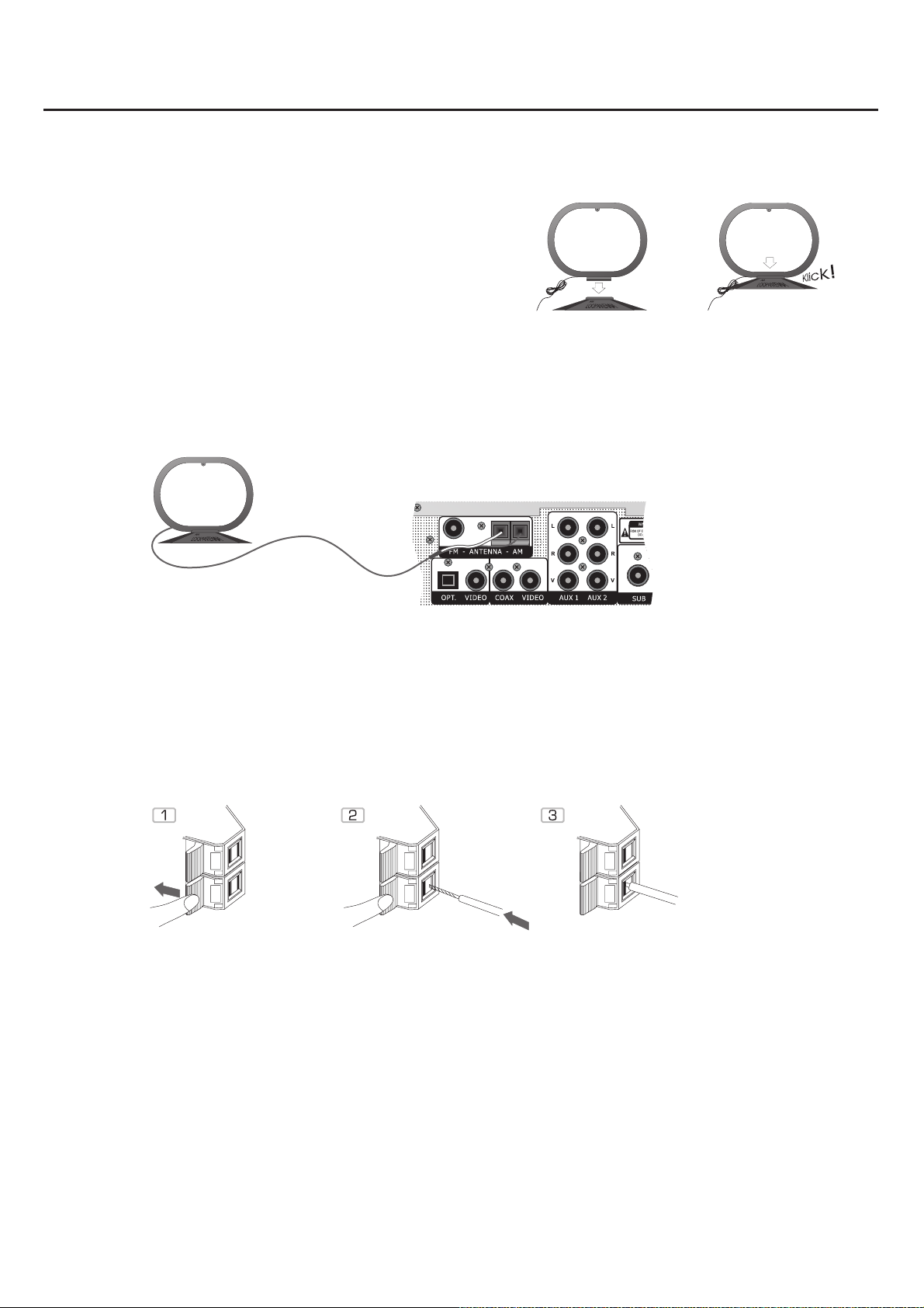
Installation of AM antenna
Install the AM antenna by mounting it on the fixing device (see
illustration).
Place the antenna in the position where the best signal is
received, as far away from the system, the television set and
the cables as possible. If the signal quality is not satisfactory,
an outdoor antenna may be required.
Connection of AM antenna
Connect the two loop antenna wires to the inputs marked AM (see illustration).
Press the corresponding button (1), insert the bare cable end into the opening
(2) and release the button again.
12
Page 13
System setup
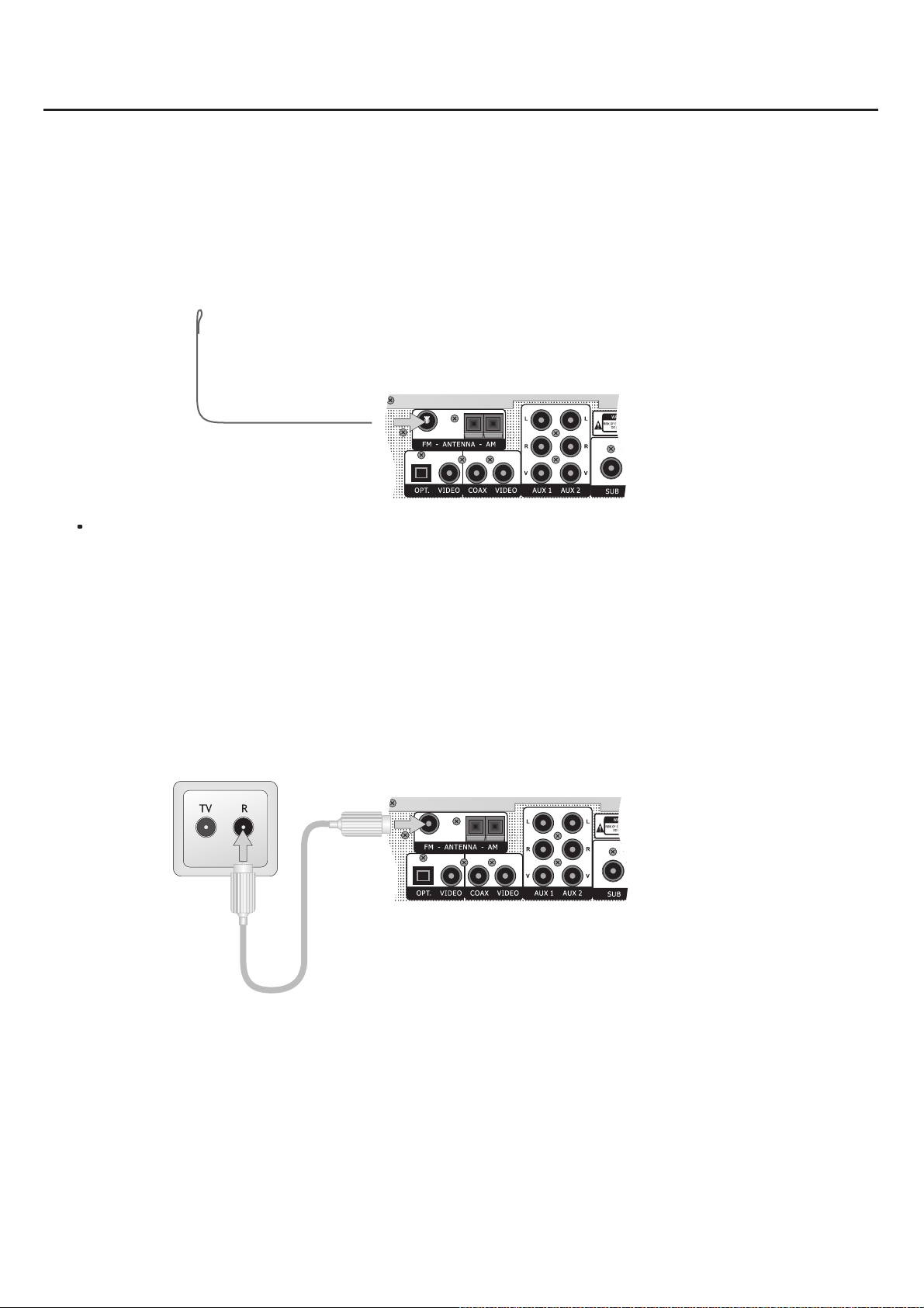
Installation and connection of FM antenna
Connect the FM indoor antenna to the antenna connection marked FM 75. For this
purpose, place the cable shoe on the pin in the middle of the connecting bush.
Tune in to a station and place the antenna in the position where the best and clearest
signal is received. If the signal quality is not satisfactory, an outdoor antenna may be
required.
FM cable connection
If you have cable television, the cable network radio connection may also be connected to this bushing.
Use a 75 Ohm antenna cable for this purpose.
75 Ohm Antenna cable
13
Page 14
System setup
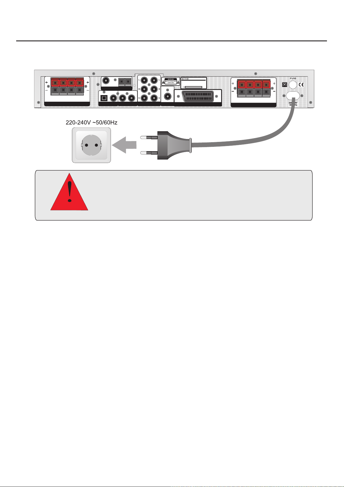
Connection to the mains supply
FM-ANTENNA-AM
RL
SPEAKER A
FRONT SPEAKEROUTPUT
RL
SPEAKER B
OPT. VIDEO COAX VIDEO AUX 1 AUX 2
Do not connect the receiver to the mains supply before all system
connections have been made correctly.
Check that all connections have been made correctly before connecting the
receiver to the mains supply.
Check that the mains voltage is 220-240V~50/60Hz before connecting the
receiver to the mains supply.
AVRECEIVER
MODEL:Cilo C-102
ITEMNO.: 11098.01
POWERSOURCE: 220-240V~50/60Hz
POWERCONSUMPTION: 200W MAX
SERIALNO.:
SUB SCART INPUT/OUTPUT
CEN. SW SR SL
SPEAKER OUTPUT
Connection to the mains supply
Before inserting the power plug into the socket it should be checked that all other system connections are
correct and safe.
Insert the power plug into a suitable socket.
If the receiver is to be used abroad, you may need an adapter.
14
Page 15
Operation and functions
STANDBY
1
DIGITAL DVD/SAT
AUX 1
AUX 2
TUNER
TV
2
MODE
DSP
TUNING BANDINPUT
C-102 HOME THEATRERECEIVER
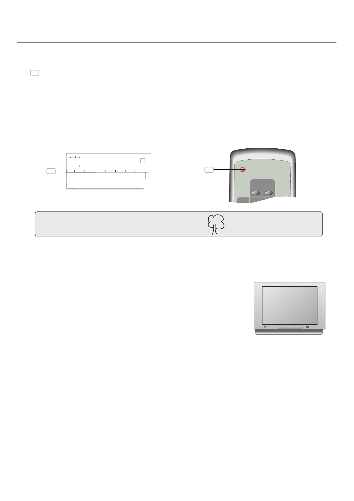
STANDBY
Standby
1
Press the STANDBY key of the remote control to switch to standby mode.
The display is switched off and all functions are reduced to a minimum.
Thus the power consumption of the receiver is reduced to a minimum. In
standby mode the receiver only responds to the STANDBY key of the
remote control.
1
1
Consider the environment and switch off the unit after use.
Selection of input source
Switch on the AV receiver and the television set, if desired.
Select the corresponding audio/video input on the television set.
Now you can call the currently active input source. Select tuner to listen to the
radio, AUX 1 or AUX 2 if an analogue device has been connected, or Optical or
Coaxial in connection with a digital signal from a DVD player or a digital satellite
receiver.
Select TV if you wish to hear a television broadcast through the receiver.
.........
.........
.........
.........
.........
.........
.........
.........
.........
.........
.........
.........
.........
.........
.........
.........
.........
.........
.........
.........
.........
.........
.........
.........
.........
.........
.........
.........
.........
.........
.........
.........
.........
.........
.........
.........
.........
.........
.........
.........
.........
.........
.........
.........
.........
.........
.........
.........
.........
.........
.........
.........
.........
.........
.........
.........
Some television sets require a special setting on the television set to ensure correct use of the SCART
channel.
If in doubt, please read the manual provided with your television set.
15
Page 16
Operation and functions
MUTE
AVR-280
VOLUME
TUNING +
RDS
MEMORY
DELAY
DSP
MODE
SPK
MODE
MODE
TEST
BASS
BOOST
BALANCE
NIGHT
DELAY
++
-
-
MONO
BAND
CENTER
REAR
AUTO
MANUAL
PR +
PR -
TUNING -
VOLUME
RDS
MEMORY
DELAY
DSP
MODE
SPK
MODE
MODE
TEST
BALANCE
NIGHT
DELAY
++
MONO
BAND
CENTER
REAR
MUTE
AVR-280
VOLUME
BASS
BOOST
AUTO
PR +
PR -
TUNING -
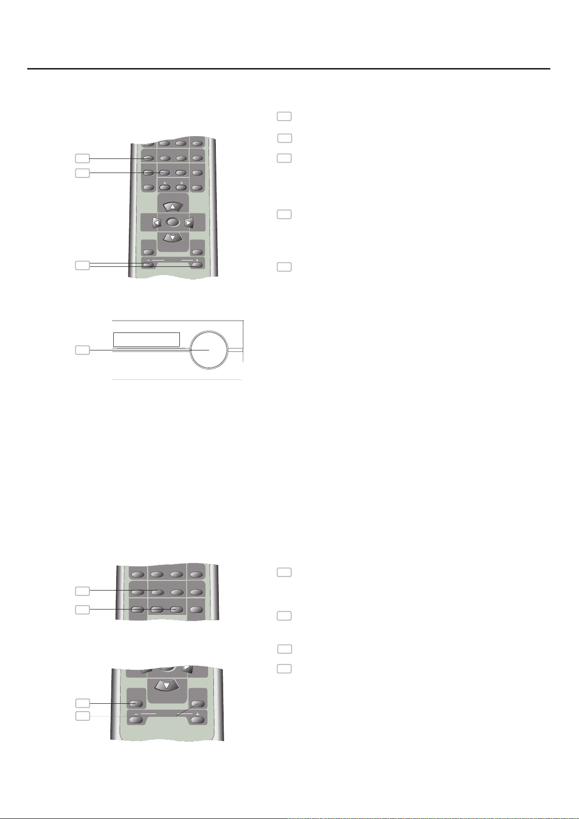
Loudspeaker setup
4
3
1
SPEAKER
Press the VOL+ key to increase the volume, press
1
the VOL- key to decrease the volume.
Turn Multijog to the right to increase the volume and
2
to the left to decrease the volume
3
Press the BALANCE key repeatedly and then the
VOL+/- keys to adjust the volume for all channels.
This way you control the balance of the front
speakers and the volume of the centre speaker,
subwoofer and rear speakers.
Press the BALANCE key repeatedly and then turn
3
Multijog (2) to adjust the volume for all channels. This
way you control the balance of the front speakers and
the volume of centre speaker, subwoofer and rear
speakers.
4
Press the SPK MODE key until "SPK CON I"* or
"SPK CON II"* is displayed. This menu will also
appear if you press the BALANCE key repeatedly.
Select the settings by means of Multijog (2).
2
* SPK CON I: This option should be selected if the
system speakers are powerful enough to reproduce
the entire frequency range.
DSP, Mode, Mute and Bass Boost
2
1
3
4
* SPK CON II: This option should be selected if the
corresponding speakers are not powerful enough to
reproduce the lower frequencies of the audio signal. If
so, channel frequencies below 180 Hz are led to the
subwoofer.
1
Press the MODE key on the remote control or on the
receiver to switch between stereo, ProLogic II-Movie
and ProLogic II-Music. DTS and Dolby Digital can
also be selected in connection with the digital inputs.
2
Press the DSP MODE key to switch between various
preset equaliser modes. The DSP MODE key is also
available on the receiver.
Press the MUTE key to make all speakers silent. This
3
is an advantage for instance if the telephone rings.
4
Use the BASS BOOST key to switch the bass boost
on or off.
16
Page 17
STANDBY
1
DIGITAL DVD/SAT
AUX 1
AUX 2
TUNER
RDS
TV
MEMORY
DSP
MODE
SPK
MODE
TEST
NIGHT
MONO
BAND
2
STANDBY
1
DIGITAL DVD/SAT
AUX 1
AUX 2
TUNER
RDS
TV
MEMORY
DSP
MODE
SPK
MODE
TEST
NIGHT
MONO
BAND
2
STANDBY
1
DIGITAL DVD/SAT
AUX 1
AUX 2
TUNER
RDS
TV
MEMORY
DSP
MODE
SPK
MODE
TEST
NIGHT
MONO
BAND
2
Operation and functions
MODE DSP TUNING BANDINPUT
C-102 HOME THEATRERECEIVER
STANDBY
MODE
DSP
TUNING BANDINPUT
C-102 HOME THEATRERECEIVER
STANDBY
MODE
DSP
TUNING BANDINPUT
C-102 HOME THEATRERECEIVER
STANDBY
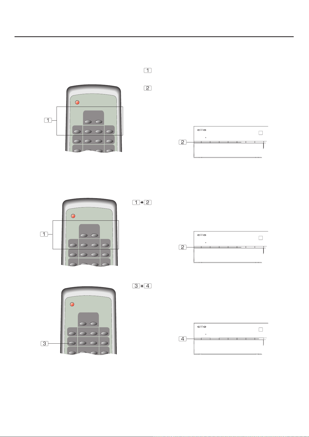
Selection of input signal
Use of radio (tuner)
Press the DIGITAL 1/DIGITAL
2/TUNER/AUX1/AUX2/TV key to select the
corresponding input.
Press the INPUT key on the front panel repeatedly to
switch between the following inputs: DIGITAL
1/DIGITAL 2/TUNER/AUX1/AUX2/TV.
Press the TUNER key on the remote control or the
INPUT key on the receiver to select tuner.
Press the BAND key on the remote control or on the
receiver to select AM or FM band.
If you have cable television, you should use the cable network radio connection for optimal radio reception.
Use a 75 Ohm antenna cable for this purpose (see page 13).
17
Page 18
Operation and functions
MUTE
VOLUME
TUNING +
DELAY
DSP
MODE
SPK
MODE
MODE
TEST
BASS
BOOST
BALANCE
NIGHT
DELAY
++
-
-
CENTER
REAR
AUTO
MANUAL
PR +
PR -
TUNING -
TUNING +
RDS
MEMORY
DELAY
DSP
MODE
SPK
MODE
MODE
TEST
BASS
BALANCE
NIGHT
DELAY
++
-
-
MONO
BAND
CENTER
REAR
AUTO
MANUAL
PR +
PR -
TUNING +
RDS
MEMORY
DELAY
DSP
MODE
SPK
MODE
MODE
TEST
BASS
BALANCE
NIGHT
DELAY
++
-
-
MONO
BAND
CENTER
REAR
AUTO
MANUAL
PR +
PR -
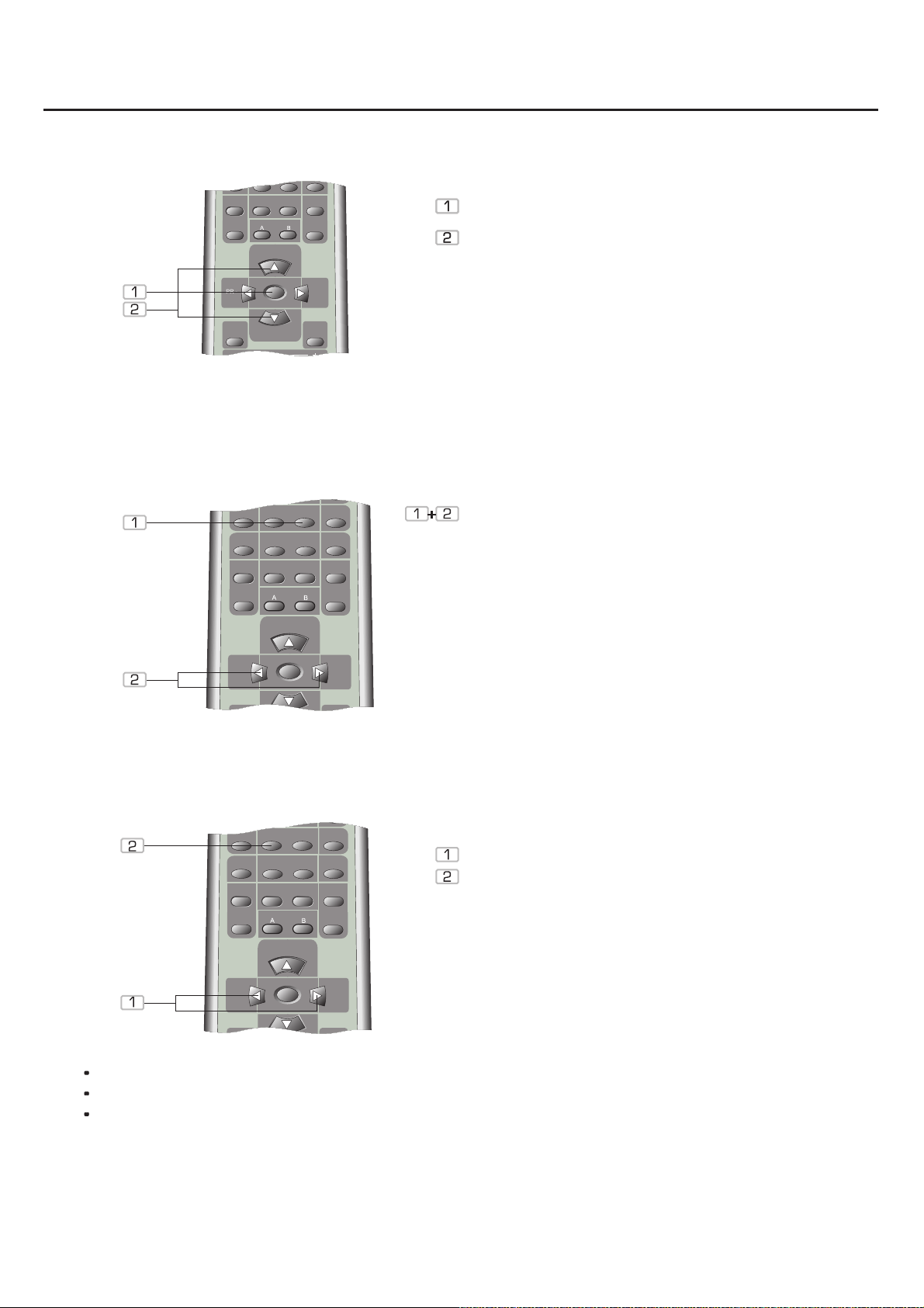
Manual and automatic tuning
SPEAKER
Storing of radio stations
Press the TUNING key to switch between "TUN
STEP" (manual) and "TUN SCAN" (automatic).
Press either the TUNING UP key or the TUNING
DOWN key to start searching.
The search function may also be activated directly
from the front panel. Press the TUNING key and start
searching by means of the Multijog.
To store a radio station, press the MEMORY key and
then the PR+/- keys to select a place to store the
station and then press the MEMORY key again to
store the station.
SPEAKER
Selection of station and RDS
RDS SCAN PS: the name of the programme (name of station)
RDS SCAN PTY: programme type registration (genre)
RDS SCAN TP: traffic radio registration (travel news)
SPEAKER
Press the PR+/- keys to select a stored station.
Press the RDS key to activate the RDS function.
Press the RDS key repeatedly to switch between
"SCAN PS", "SCAN PTY" and "SCAN TP".
18
Page 19
STANDBY
1
DIGITAL DVD/SAT
AUX 1
AUX 2
TUNER
RDS
TV
MEMORY
DSP
MODE
SPK
MODE
TEST
NIGHT
MONO
BAND
2
STANDBY
1
DIGITAL DVD/SAT
AUX 1
AUX 2
TUNER
RDS
TV
MEMORY
DSP
MODE
SPK
MODE
TEST
NIGHT
MONO
BAND
2
Operation and functions
TUNING +
1
DIGITAL DVD/SAT
AUX 1
AUX 2
TUNER
RDS
TV
MEMORY
DELAY
DSP
MODE
SPK
MODE
MODE
TEST
BALANCE
NIGHT
DELAY
++
-
-
MONO
BAND
CENTER
REAR
2
Selection of digital optical / coaxial inputs
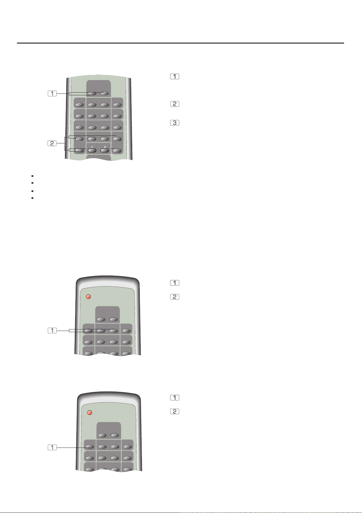
Press the DIGITAL 1/DIGITAL 2 keys to activate the
digital inputs. Check that the Setup (digital output) of
the peripheral devices are set at RAW and bitstream
respectively.
Depending on the size of the room, the speakers may
be configured through CENTRE DELAY and
SURROUND DELAY.
Selection is also possible through the front panel by
pressing the INPUT key repeatedly.
SPEAKER
Digital 1: Optical digital input
Digital 2: Coaxial digital input
Centre delay: The centre channel is delayed if the front speakers are placed very far apart!
Surround delay: Depending on the listening position the surround channels should be reduced or increased.
The distance from the listening position to all the individual speakers should be the same.
Night:
reduce strong dynamic peaks. The difference between the murmur of a river and a bomb explosion is
reduced.
Press this key for dynamic compression of the DTS or Dolby Digital sound. This can be used to
Selection of analogue AUX 1 / AUX 2 inputs
TV selection
Press the AUX 1/ AUX 2 keys to activate the analogue
inputs.
Selection is also possible through the front panel by
pressing the INPUT key repeatedly.
Press the TV key to activate the analogue SCART
input/output.
Selection is also possible through the front panel by
pressing the INPUT key repeatedly.
19
Page 20

Te c h n i c a l d a t a
Frequency respons 20-20.000Hz
S/N >105dB
THD <0.1%
Digital inputs Optical and coaxial
Analog input RCA
Video input RCA
Power 220-240V~50/60Hz
Power consumption 200W
Music power
Measures 430 x 68 x 330mm
Weight ca. 6kg.
5x60W+1x100W
We reserve the right to change the technical data and design without notice as a result of further
development.
20
Page 21
Troubleshooting
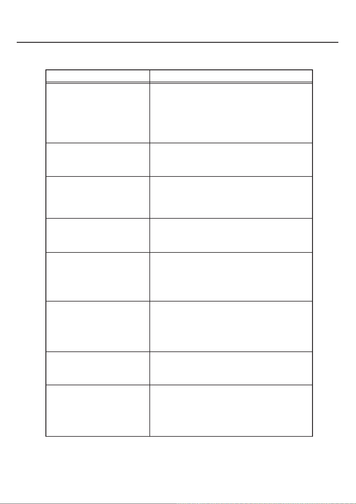
PROBLEM CAUSE/REMEDY
Nothing happens, all displays are
dark.
Only the POWER LED is alight.
The system does not respond to
the remote control.
Systemet leverer ingen lyd. The cable connections of the speaker terminals are
No sound on the digital input.
The mains plug has not been inserted (don't laugh check it out!)
There is no mains voltage. Check that the socket used
carries current (e.g. by means of a lamp).
The receiver is not switched on.
The receiver is in standby mode. Press the STANDBY key
on the remote control.
Check that no objects block the way between remote
control and receiver. Replace the remote control
batteries.
loose or have no contact. Press the TEST key on the
remote control.
Check the setup settings. Set the DVD player in the
Setup menu. Set Audio out to the data format RAW or
bitstream. Check the digital input connected and select
it.
The receiver does not receive the
radio station properly.
No reproduction of TV signals or
incorrect reproduction.
No reproduction of analogue
signals through AUX or incorrect
reproduction.
We reserve the right to change the technical data and design without notice as a result of further
development.
Check that the indoor antenna is correctly positioned and,
if the house connection is used, check that the signal is
correct. Check the cable for fracture.
Check the SCART connection, that the SCART cable is
fully mounted and that SCART IN/OUT has been
selected on the television set.
Check that that the RCA plugs are correctly inserted into
the inputs, that AUX 1 / AUX 2 have been properly
selected, and that the speaker volume is not set at 0 for
reproduction of portable devices (CD/MP3/MiniDisc
players)
21
Page 22
Item No.: 40043
 Loading...