

Page 1
MIGTRN0001 Issue 2 14/09/98
Operating Manual
TRANSMIG 210 Compact Power Source 704832
Remote Power Source 704808
TRANSMIG 250 Compact Power Source 704833
Remote Power Source 704809
2R TRANSMIG 210/250 Wirefeeder 704975
TRANSMIG 310 Compact Power Source 704836
TRANSMIG 330 Remote Power Source 705085
2R TRANSMIG 330 Wirefeeder 704841
Page 2

OperatingManual Transmig 210, 250, 310, 330
CONTENTS
Page
DOC No: MIGTRN0001 Page 1 of 31
Issue No: 2 Date: 14/09/98
1. INTRODUCTION..................................................................................................................7
1.1 Duty Cycle................................................................................................................................................7
2. SPECIFICATIONS................................................................................................................8
2.1 Transmig 210 and Transmig 250 Specifications.........................................................................................8
2.2 Transmig 310 and Transmig 330 Specifications.........................................................................................9
2.3 MIG Torch Specifications.........................................................................................................................9
2.4 Wirefeeder Specifications........................................................................................................................10
2.5 Plant Contents.........................................................................................................................................10
2.6 Optional Accessories...............................................................................................................................11
3. INSTALLATION RECOMMENDATIONS.......................................................................12
3.1 Environment............................................................................................................................................12
3.2 Location..................................................................................................................................................12
3.3 Ventilation..............................................................................................................................................12
3.4 Mains Supply Voltage Requirements.......................................................................................................12
3.5 Alternative Mains Supply Voltage Requirements.....................................................................................13
4. SET UP FOR COMPACT TRANSMIGS...........................................................................14
5. SET UP FOR REMOTE TRANSMIG WITH WIREFEEDER.........................................15
5.1 Power Source Connections......................................................................................................................15
5.2 Wirefeeder Connections...........................................................................................................................15
6. Power Source / 2R Wirefeeder Controls, Indicators and Features.....................................16
6.1 Indicator Light........................................................................................................................................16
6.2 Standby/Coarse Voltage Control Switch and Fine Voltage Control Switch...............................................16
6.3 Digital Ammeter and Voltmeter (Standard for Transmig 330 Only)..........................................................17
6.4 Torch Polarity Lead (Compact Models Only)...........................................................................................17
6.5 Positive and Negative Welding Terminals................................................................................................17
6.6 Wirefeeder Control Socket (Remote Wirefeeder Models Only).................................................................17
6.7 Thermal Overload...................................................................................................................................17
6.8 Choice of Inductance Setting (Transmig 210 & 250 Only).......................................................................18
6.9 Wirespeed Control (Compact Models & 2R Wirefeeder Only)..................................................................18
6.10 Spot Timer (Compact Models & 2R Wirefeeder Only)...........................................................................18
6.11 Dwell Timer (Compact Models & 2R Wirefeeder Only).........................................................................18
6.12 Mode Selector Switch (Compact Models & 2R Wirefeeder Only)...........................................................18
6.13 Burnback Control (Compact Models & 2R Wirefeeder Only).................................................................18
6.14 Wirefeeder Driver Roller Pressure Adjustment (Compact Models & 2R Wirefeeder Only)......................19
6.15 Wire Reel Brake (Compact Models & 2R Wirefeeder Only)...................................................................19
7. TWECO MIG TORCH (P/N 717578 where supplied)........................................................19
7.1 Introduction............................................................................................................................................19
7.2 Torch Consumable Parts.........................................................................................................................19
Page 3

Transmig 210, 250, 310, 33
CONTENTS
Page
Page 2 of 31 DOC No: MIGTRN0001
Date: 14/09/98 Issue No: 2
7.3 MIG Torch Components.........................................................................................................................21
7.4 Installing A New Conduit Liner...............................................................................................................22
7.5 MIG Torch Maintenance.........................................................................................................................22
8. BASIC WELDING TECHNIQUE.......................................................................................23
8.1 Setting of the Power Source & Wirefeeder...............................................................................................23
8.2 Position of MIG Torch............................................................................................................................23
8.3 Distance from the MIG Torch Nozzle to the Work Piece..........................................................................23
8.4 Travel Speed...........................................................................................................................................23
8.5 Stitch Welding Operation........................................................................................................................23
8.6 Spot Welding Operation..........................................................................................................................24
9. ROUTINE MAINTENANCE & INSPECTION..................................................................24
9.1 Improved Current Accuracy Calibration Procedure for the Digital Meter..................................................25
10. BASIC TROUBLESHOOTING.........................................................................................26
10.1 Solving Problems Beyond the Welding Terminals..................................................................................26
10.2 Welding Problems.................................................................................................................................28
10.3 Power Source Problems.........................................................................................................................29
10.4 Key Spare Parts....................................................................................................................................31
Page 4

Transmig 210, 250, 310, 330
CONTENTS
Page
DOC No: MIGTRN0001 Page 5 of 31
Issue No: 2 Date: 14/09/98
TABLES
Table 1 - Factory fitted Mains supply leads fitted to the Transmig Power Sources..................................13
Table 2 - Mains supply lead sizes for alternative Mains supply voltages..................................................13
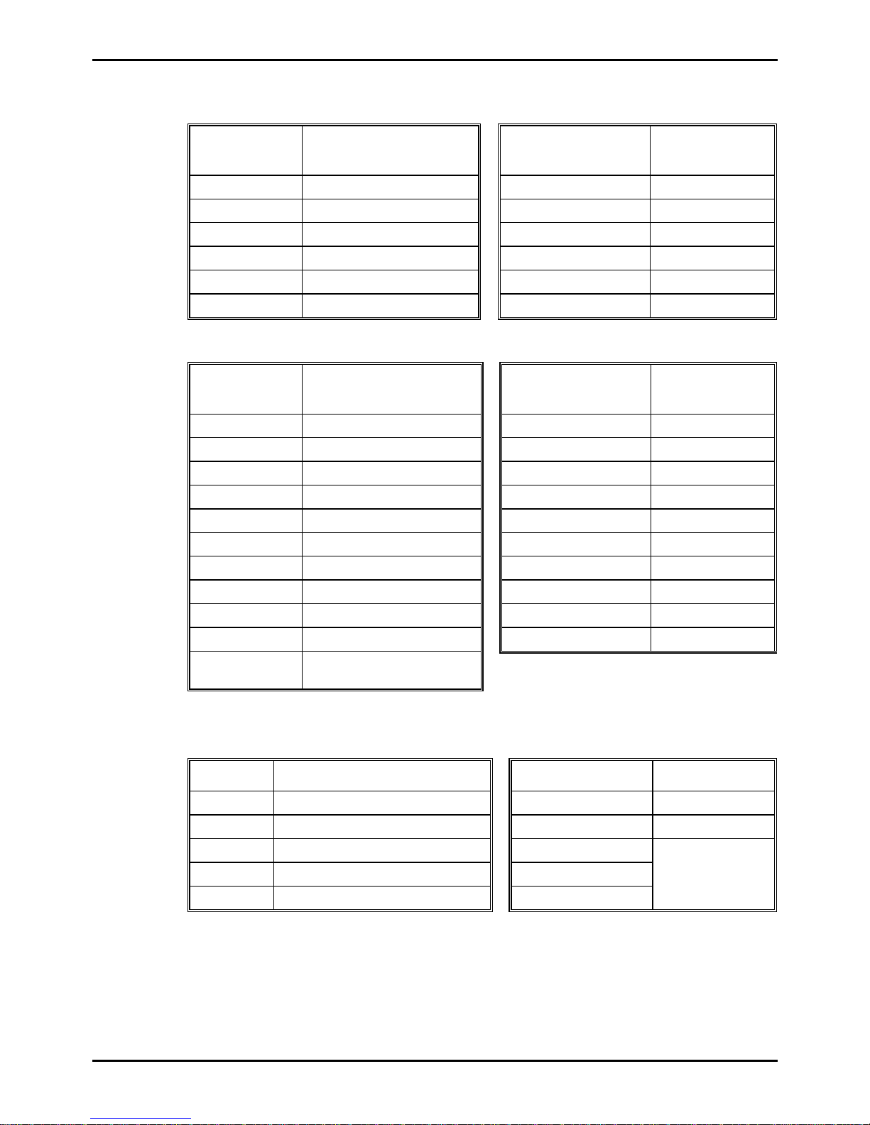
Table 3 - MIG torch gas diffusers..........................................................................................................19
Table 4 - MIG torch contact tips............................................................................................................20
Table 5 - MIG torch nozzles..................................................................................................................20
Table 6 - MIG torch conduit liners.........................................................................................................20
Table 7 - MIG Torch components..........................................................................................................21
Page 5

Transmig 210, 250, 310, 330
FIGURES
Page
Page 6 of 31 DOC No: MIGTRN0001
Date: 14/09/98 Issue No: 2
Figure 1 - Transmig duty cycle curves.....................................................................................................7
Figure 2 - Voltage settings for Transmig 210/250..................................................................................13
Figure 3 - Voltage settings for Transmig 310/330..................................................................................13
Figure 4 - Compact Transmig Setup......................................................................................................14
Figure 5 - Remote Transmig Setup........................................................................................................15
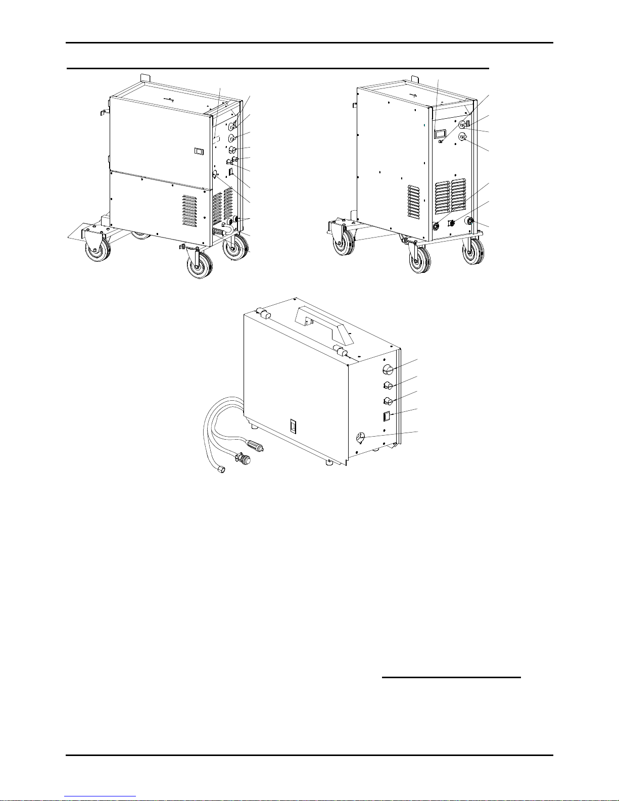
Figure 6 - Compact Transmig controls...................................................................................................16
Figure 7 - Remote Transmig controls.....................................................................................................16
Figure 8 - Wirefeeder controls...............................................................................................................16
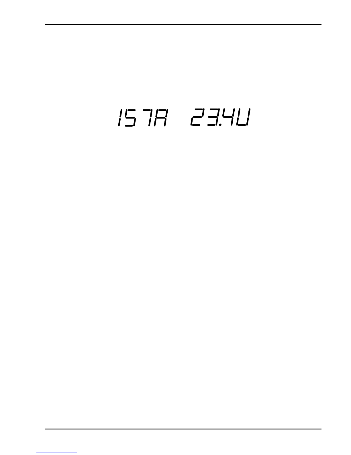
Figure 9 - Examples of the digital read outs...........................................................................................17
Figure 10 - Exploded view of MIG torch...............................................................................................21
Figure 11 - Conduit liner trim length......................................................................................................22
Figure 12 - MIG Torch angle.................................................................................................................23
Page 6
Transmig 210, 250, 310, 330
DOC No: MIGTRN0001 Page 7 of 31
Issue No: 2 Date: 14/09/98
1. INTRODUCTION
The Transmig 210, 250, 310 and 330 are semi-automatic Gas Metal Arc Welder (GMAW-commonly
MIG) with either integrated or separate wire feed unit. These products are designed to meet the broad
operating needs of the metal fabrication industry where production efficiency is vital. They are designed
and manufactured in Australia to Australian Standard AS1966.1-1985.
The Transmig range gives excellent performance on mild steel, stainless steel, aluminium, silicon bronze
and some hard facing wires with the Argon based of shielding gases. The Transmig range also gives
excellent results on mild steel using CO2 (carbon dioxide) shielding gas.
The Transmig Plants are supplied as a complete welding package (apart from gas cylinder and electrode
wire). The following instructions detail how to correctly set up your new Transmig and give guidelines on
gaining the best production efficiency. Please read these instructions thoroughly before using your
Transmig.
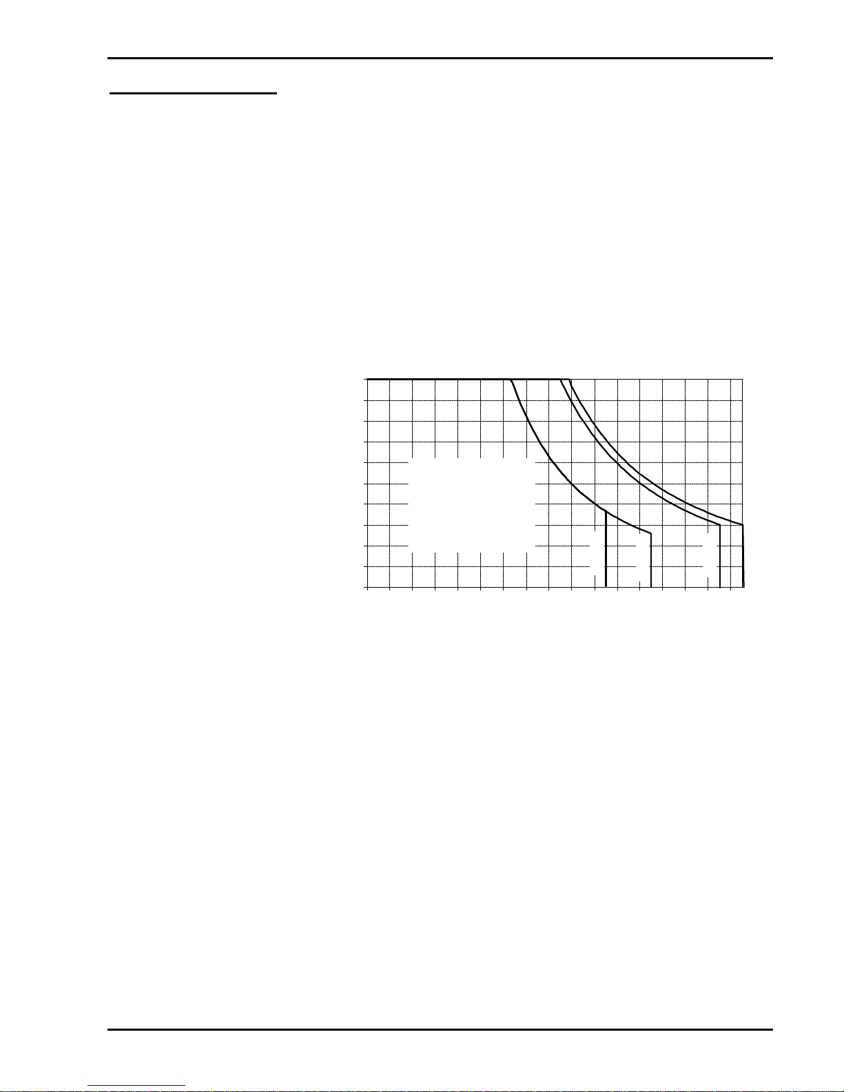
1.1 Duty Cycle
The rated duty cycle
of a welding Power
Source is the
operating time it may
be used at its rated
output current without exceeding the
temperature limits of
the insulation of the
component parts. In
Australia a duty cycle
period of 5 minutes is
specified in Australian
Standard AS 1966
Part 1-1985. To
explain the 5 minute
duty cycle period the following example is used. Suppose a welding Power Source is designed to
operate at 30% duty cycle, 250 amperes at 26 volts. This means that it has been designed and built
to provide the rated amperage (250A) at the rated voltage (26V), for 1.5 minutes out of every 5
minute period (30% of 5 minutes is 1.5 minutes). During the other 3.5 minutes of the 5 minute
period the Power Source must idle and be allowed to cool. The thermal cut-out will operate if the
duty cycle is exceeded.
CAUTION 1: The above times are not accumulative.
0
10
20
30
40
50
60
70
80
90
100
0
20
40
60
80
100
120
140
160
180
200
220
240
260
280
300
320
Welding Current (amp)
Duty Cycle (percentage)
330
Transmig 210
Transmig 250
Safe
Operating
Region
210
250
Transmig 310
Transmig 330
Figure 1 - Transmig duty cycle curves
Page 7
Transmig 210, 250, 310, 330
Page 8 of 31 DOC No: MIGTRN0001
Date: 14/09/98 Issue No: 2
2. SPECIFICATIONS
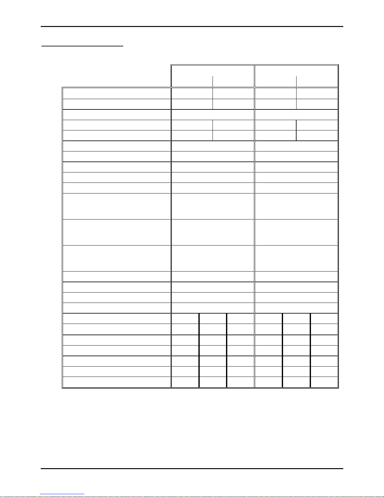
2.1 Transmig 210 and Transmig 250 Specifications
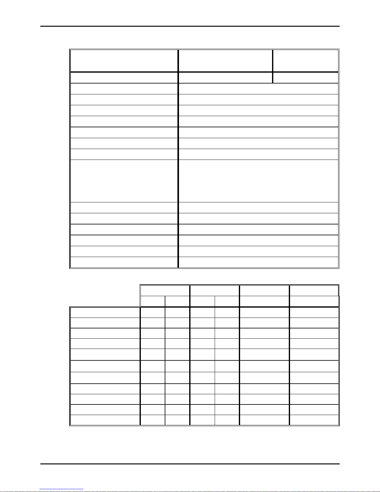
Transmig 210 Transmig 250
Compact Remote Compact Remote
Plant Assembly part number
704830 704831 704833 704834
Plant Mass 77Kg 107Kg 78Kg 108Kg
Plant Dimensions 860mm x 490mm x 845mm 860mm x 490mm x 845mm
Power Source part number
704832 704808 704835 704809
Power Source Mass 60Kg 58.5Kg 61Kg 59.5Kg
Power Source Dimensions 640 x 310 x 732 640 x 310 x 732
Number of Phases Single Phase Single Phase
Frequency 50 / 60 Hz 50 / 60 Hz
Open Circuit Voltage Range 18.9 to 34.2V 19 to 43V
Output Current Range 25 to 210A 30 to 250A
Rated Output for 15A Outlet at 240V
210A @ 25%
148A @ 50%
105A @ 100%
184A @ 25%
130A @ 50%
92A @ 100%
µRated Output for 20A Outlet at 240V
210A @ 36%
164A @ 60%
127A @ 100%
¾
ÙRated Output for 25A Outlet at 240V
¾
250A @ 25%
180A @ 50%
127A @ 100%
Duty Cycle Period 5 minutes or 10 minutes 5 minutes or 10 minutes
Number of Output Voltage Values 16 16
Wire Size Range 0.6 - 0.9 Hard / 0.9 - 1.2 Soft 0.6 - 0.9 Hard / 0.9 - 1.2 Soft
Operating Temperature Range 0°C to 40°C 0°C to 40°C
Primary input voltage 200V 220V 240V 200V 220V 240V
ÑRated Input Current (output of 127A)
25A 23A 21A 30A 27A 25A
Rated kVA (output of 127A)
5kVA 5kVA 5kVA 6kVA 6kVA 6kVA
Maximum Input Current 42A 38A 35A 52A 47A 43A
Generator Requirements 8.5kVA 8.5kVA 8.5kVA 10kVA 10kVA 10kVA
Rated Outlet @ Max Duty Cycle 25A 23A 20A 30A 27A 25A
ªFuse Size @ Max Duty Cycle 50A 50A 40A 60A 60A 50A
Ñ The Rated Input Current should be used for the determination of cable size & supply
requirements.
ªMotor start fuses or motor start thermal circuit breakers are recommended for this application.
Australian Standard AS3000 (Clause 2.4.3.4) permits the use of a fuse or circuit breaker rated at
two times the rated input current.
µTo achieve this rating, the 15 Amp plug and primary supply lead (as supplied) must be replaced
with a 20 Amp plug & lead. This must be carried out by a qualified electrical tradesperson.
Page 8
Transmig 210, 250, 310, 330
DOC No: MIGTRN0001 Page 9 of 31
Issue No: 2 Date: 14/09/98
ÙTo achieve this rating, the 15 Amp plug and primary supply lead (as supplied) must be replaced
with a 25 Amp plug & lead. This must be carried out by a qualified electrical tradesperson.
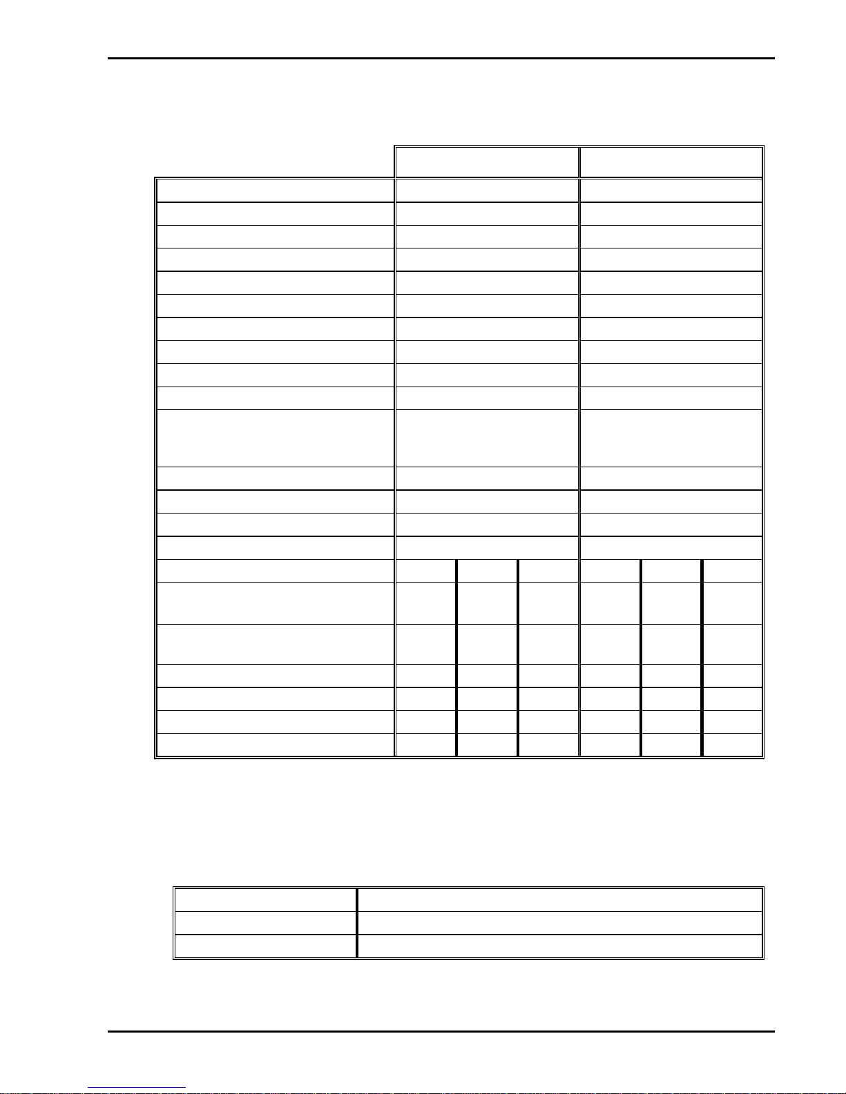
2.2 Transmig 310 and Transmig 330 Specifications
Transmig 310 Transmig 330
Plant Assembly part number
704836 704839
Plant Mass 87Kg 117Kg
Plant Dimensions 860mm x 490mm x 845mm 860mm x 490mm x 845mm
Power Source part number
704838 705085
Power Source Mass 71Kg 70Kg
Power Source Dimensions 640 x 310 x 732 640 x 310 x 732
Number of Phases Three Phase Three Phase
Frequency 50 / 60 Hz 50 / 60 Hz
Open Circuit Voltage Range 17.5 to 41.2V 17.5 to 41.2V
Output Current Range 25 to 310A 25 to 330A
Rated Output Duty Cycle
310A @ 30%
220A @ 60%
170A @ 100%
330A @ 30%
228A @ 60%
177A @ 100%
Duty Cycle Period 5 minutes or 10 minutes 5 minutes or 10 minutes
Number of Output Voltage Values 24 24
Wire Size Range 0.6 - 1.2 Hard / 0.9 - 1.2 Soft 0.6 - 1.2 Hard / 0.9 - 1.2 Soft
Operating Temperature Range 0°C to 40°C 0°C to 40°C
Primary input voltage 220V 380V 415V 220V 380V 415V
ÑRated Input Current for output current
at 100% duty cycle.
21A 12A 11A 21A 12A 11A
Rated kVA for output current at
100% duty cycle.
8kVA 8kVA 8kVA 8kVA 8kVA 8kVA
Maximum Input Current 36A 21A 19A 38A 22A 20A
Generator Requirements 13.7kVA13.7kVA13.7kVA14.4kVA14.4kVA14.4kVA
Rated Outlet @ Max Duty Cycle 25A 15A 15A 25A 15A 15A
ªFuse Size @ Max Duty Cycle 50A 30A 20A 50A 30A 20A
Ñ The Rated Input Current should be used for the determination of cable size & supply
requirements.
ªMotor start fuses or motor start thermal circuit breakers are recommended for this application.
Australian Standard AS3000 (Clause 2.4.3.4) permits the use of a fuse or circuit breaker rated at
two times the rated input current.
2.3 MIG Torch Specifications
Torch Part Number 717578
Torch Type TWECO 250A (Eliminator Consumables)
Torch Cable Length 3.6 metre
Page 9
Transmig 210, 250, 310, 330
Page 10 of 31 DOC No: MIGTRN0001
Date: 14/09/98 Issue No: 2
2.4 Wirefeeder Specifications
Wirefeeder
704975
(Transmig 210 & 250 Remote)
704841
(Transmig 330)
Mass 21Kg 23Kg
Dimensions 600 x 245 x 475
Motor Supply Voltage 36V AC
Motor Supply VA 180VA
Control Supply Voltage 24V AC
Control Supply VA 30VA
Minimum Wire Speed One metre per minute
Maximum Wire Speed 17 metres per minute
Wire Diameter: Mild Steel 0.6, 0.8, 0.9
Stainless Steel 0.8, 0.9
Aluminium 0.9, 1.0, 1.2
Flux Cored 0.8, 0.9, 1.2
Operating Temperature Range 0°C to 40°C
Wire Spool Size 15Kg Maximum
Spot Time Range 0 to 2.5 Seconds
Stitch ‘ON‘ Time 0 to 2.5 Seconds
Stitch ‘OFF‘ Time 0 to 2.5 Seconds
Burnback Time Range 0 to 0.15 Seconds
2.5 Plant Contents
Transmig 210 Transmig 250 Transmig 310 Transmig 330
CompactRemoteCompactRemote Compact Remote
Wheeling Kit
4 4 4 4 4 4
Roll on Cylinder Carrier
4 4 4 4 4 4
Power Source
4 4 4 4 4 4
Operating Instructions
4 4 4 4 4 4
3 Metre Work Lead
4
¾
4
¾
4
¾
8 Metre Work Lead
¾
4
¾
4
¾
4
2R Wirefeeder (8 metre)
¾
4
¾
4
¾
4
Regulator / Flowmeter
4 4 4 4 4 4
TWECO MIG torch 250A
4 4 4 4 4 4
Feed Roller 0.6/0.8 Hard
4 4 4 4 4 4
Feed Roller 0.9/1.2 Hard
4 4 4 4 4 4
Page 10

Transmig 210, 250, 310, 330
DOC No: MIGTRN0001 Page 11 of 31
Issue No: 2 Date: 14/09/98
2.6 Optional Accessories
Part Description Transmig 210 Transmig 250 Transmig 310Transmig 330
Number
CompactRemoteCompactRemote Compact Remote
705103 Digital Meter Kit
4 4 4 4 4
Standard
704914 Wirefeeder Swivel Base
¾
4
¾
4
¾
4
704913 Wirefeeder Trolley
¾
4
¾
4
¾
4
704917 110Volt Aux Supply Kit
4 4 4 4 4 4
ELC2123035250A Eliminator torch (3.6M)
(fits Transmig adaptor)
4 4 4 4 4 4
ELC4123545450A Eliminator torch (3.6M)
(fits Transmig adaptor)
4 4 4 4 4 4
704343 Torch trigger lead to suit
Eliminator torch
4 4 4 4 4 4
704099 Work lead (3m)
4 4 4 4
¾ ¾
705163 Work lead (3m)
¾ ¾ ¾ ¾
4 4
704829 Work lead (8m)
4 4 4 4
¾ ¾
704828
Work lead (8m)
¾ ¾ ¾ ¾
4 4
704912 8 M Interconnection Extension
¾
4
¾
4
¾ ¾
704465 8 M Interconnection Extension
¾ ¾ ¾ ¾ ¾
4
717162 TWECO No.2 torch (3.6M)
(adaptor 704915 required)
4 4 4 4 4 4
717201 TWECO No.4 torch (3.6M)
(adaptor 704915 required)
4 4 4 4 4 4
704915 TWECO No.2 & 4 Adaptor
4 4 4 4 4 4
7977036 Feed roll, 0.6/0.8 Hard Wire
4 4 4 4 4 4
7977660 Feed roll, 0.9/1.2 Hard Wire
4 4 4 4 4 4
7977037 Feed roll, 1.0/1.2 Hard Wire
4 4 4 4 4 4
7977731 Feed roll, 0.8/0.9 Soft Wire
4 4 4 4 4 4
7977264 Feed roll, 1.0/1.2 Soft Wire
4 4 4 4 4 4
7977732 Feed roll, 0.8/0.9 Flux cored
4 4 4 4 4 4
704277 Feed roll, 1.0/1.2 Flux cored
4 4 4 4 4 4
ELC94L Eliminator Torch trigger lock
4 4 4 4 4 4
705000 MIG pliers (size No 1)
4 4 4 4 4 4
705001 MIG pliers (size No 2)
4 4 4 4 4 4
646265 Weld measurement gauge
4 4 4 4 4 4
705277 Auxiliary transformer kit
240/36/24V
4 4
¾ ¾ ¾ ¾
705278 Auxiliary transformer kit 240-
220-200/36/24V
¾ ¾
4 4
¾ ¾
705126 Auxiliary transformer kit 415-
380-220/36/24V
¾ ¾ ¾ ¾
4 4
Page 11

Transmig 210, 250, 310, 330
Page 12 of 31 DOC No: MIGTRN0001
Date: 14/09/98 Issue No: 2
3. INSTALLATION RECOMMENDATIONS
3.1 Environment
The Transmigs are NOT designed for use in environments with increased hazard of electric shock as
defined in AS3195-1990.
a) Examples of environments with increased hazard of electric shock are -
i) In locations in which freedom of movement is restricted, so that the operator is
forced to perform the work in a cramped (kneeling, sitting or lying) position with
physical contact with conductive parts;
ii) In locations which are fully or partially limited by conductive elements, and in which
there is a high risk of unavoidable or accidental contact by the operator, or
iii) In wet or damp hot locations where humidity or perspiration considerable reduces the
skin resistance of the human body and the insulation properties of accessories.
b) Environments with increased hazard of electric shock do not include places where
electrically conductive parts in the near vicinity of the operator, which can cause increased
hazard, have been insulated.
3.2 Location
Be sure to locate the Power Source according to the following guidelines:
a) In areas, free from moisture and dust.
b) Ambient temperature 0°C to 40°C.
c) In areas, free from oil, steam and corrosive gases.
d) In areas, not subjected to abnormal vibration or shock.
e) In areas, not exposed to direct sunlight or rain.
f) Place at a distance of 30cm or more from walls or similar that could restrict natural air flow
for cooling.
g) The minimum ground clearance for these products is 140mm.
3.3 Ventilation
Since the inhalation of welding fumes can be harmful, ensure that the welding area is effectively
ventilated.
3.4 Mains Supply Voltage Requirements
The Mains supply voltage should be within ± 10% of the rated Mains supply voltage. Too low a
voltage may cause poor welding performance or the wirefeeder malfunction. Too high a supply
voltage will cause components to overheat and possibly fail.
The Transmig is supplied with an input lead to which an appropriate plug should be fitted.
Install a power outlet for each Power Source and fit fuses as per Transmig 210 and Transmig 250
Specifications or Transmig 310 and Transmig 330 Specifications.
WARNING 1: CIGWELD advises that your Transmig be electrically connected by a qualified
electrical tradesperson.
Refer to Table 1 for the ratings of the Mains supply leads that are supplied with the various Transmig
Power Sources.
Page 12
Transmig 210, 250, 310, 330
DOC No: MIGTRN0001 Page 13 of 31
Issue No: 2 Date: 14/09/98
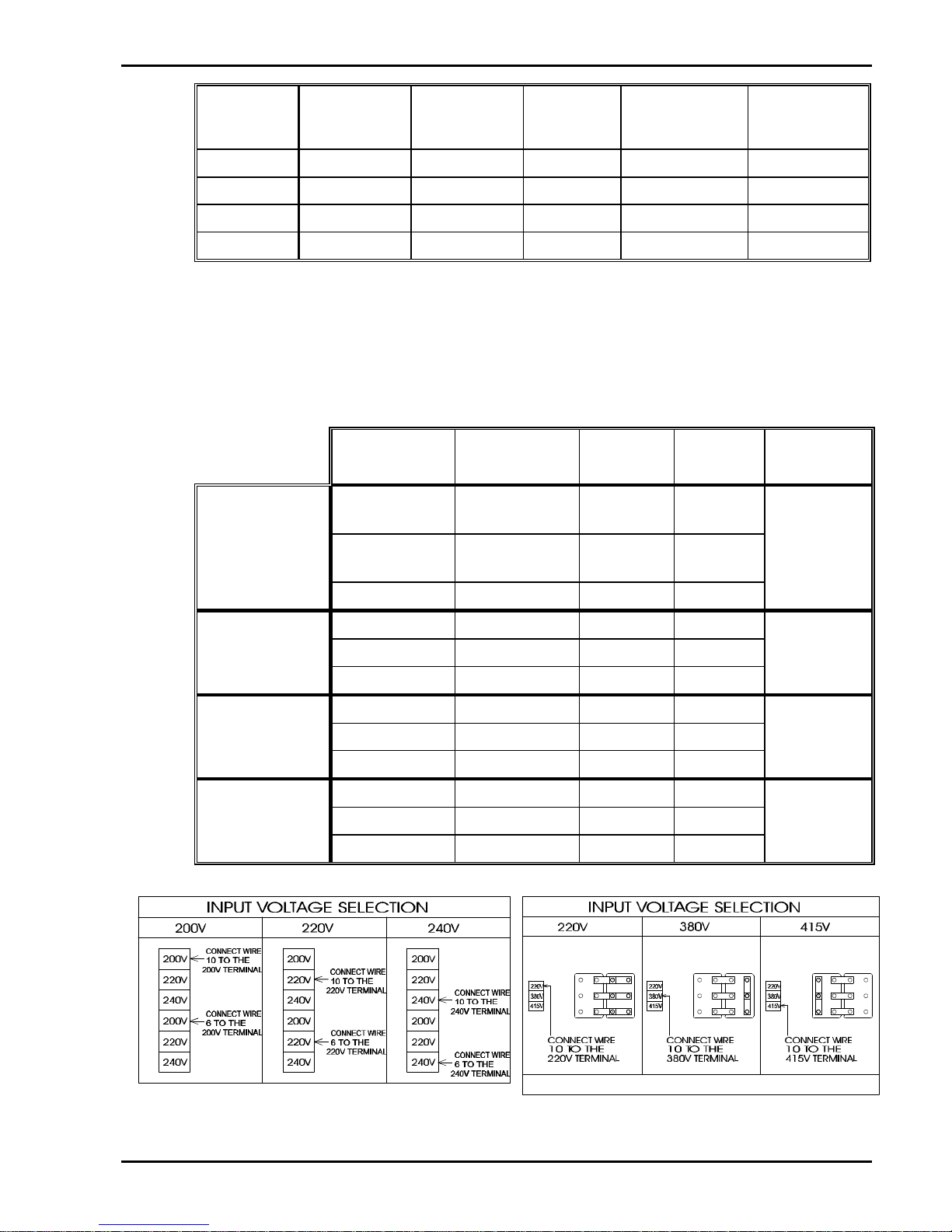
Transmig
Mains
Supply Lead
Size
Lead
Current
Rating
Lead
Length
Machine
Voltage
Setting
Duty Cycle
210 1.5mm
2
16 Amps 3 metre 240 Volt 210A @ 25%
250 1.5mm
2
16 Amps 3 metre 240 Volt 184A @ 25%
310 1mm
2
12 Amps 3.7 metre 415/440 Volt 310A @ 30%
330 1mm
2
12 Amps 3.7 metre 415/440 Volt 330A @ 30%
Table 1 - Factory fitted Mains supply leads fitted to the Transmig Power Sources
CAUTION 2:The Transmig Mains supply leads should be replaced with leads as specified in Table
2 when the Transmigs Mains supply voltage is changed or when it is plugged into a
higher rated Mains outlet.
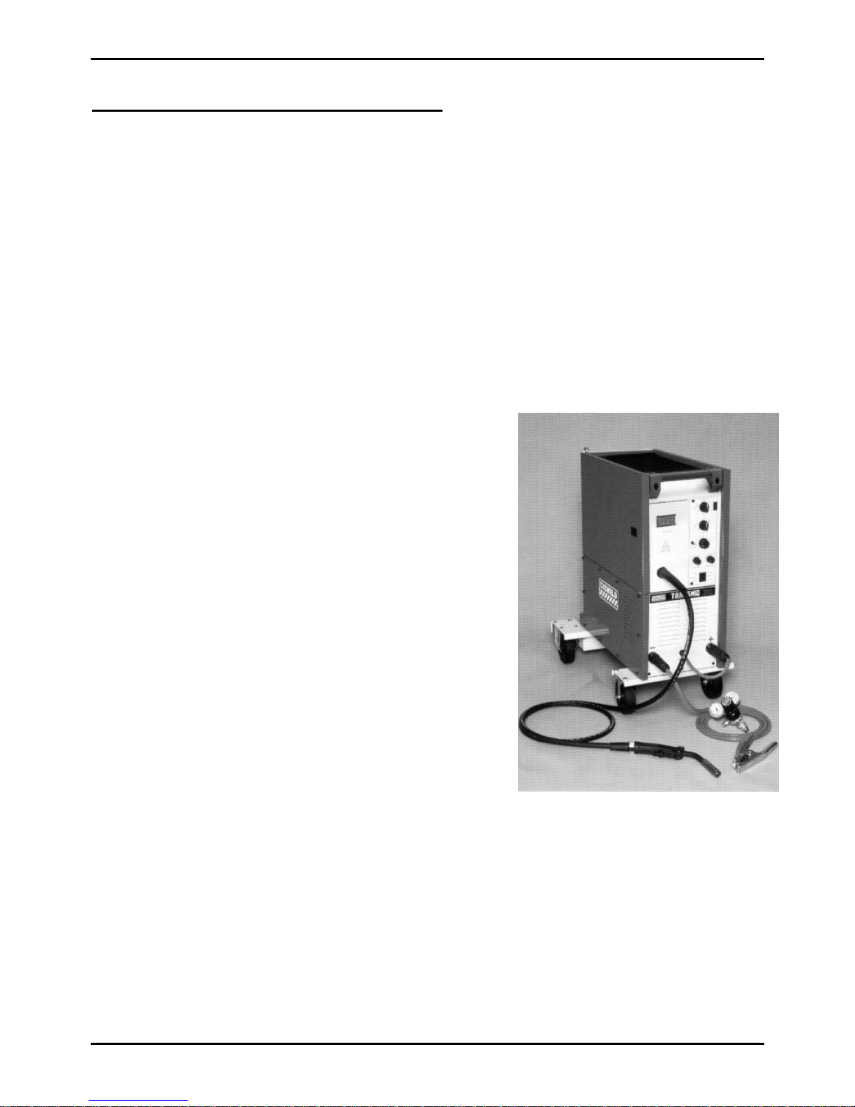
3.5 Alternative Mains Supply Voltage Requirements
The Power Sources are suitable for the following Mains supply voltages:
Mains Supply
Voltage Setting
Mains Supply
Lead Size
Mains
Outlet Size
Fuse Size Machines
Duty Cycle
Export Model
Only
200 Volt 4mm
2
25 Amp ª 50 Amp
Export Model
Only
220 Volt 4mm
2
25 Amp ª 50 Amp210A @ 36%
Transmig 210 240 Volt 2.5mm
2
20 Amp ª 40 Amp
200 Volt 6mm
2
30 Amp ª 60 Amp
Transmig 250 220 Volt 6mm
2
30 Amp ª 60 Amp250A @ 25%
See Figure 2 240 Volt 4mm
2
25 Amp ª 50 Amp
220 Volt 2.5mm
2
20 Amp ª 40 Amp
Transmig 310 380 Volt 1.5mm
2
15 Amp ª 20 Amp310A @ 30%
See Figure 3 415/440 Volt 1mm
2
15 Amp ª 20 Amp
220 Volt 2.5mm
2
20 Amp ª 40 Amp
Transmig 330 380 Volt 1.5mm
2
15 Amp ª 20 Amp330A @ 30%
See Figure 3 415/440 Volt 1mm
2
15 Amp ª 20 Amp
Table 2 - Mains supply lead sizes for alternative Mains supply voltages
Figure 2 - Voltage settings for Transmig 210/250 Figure 3 - Voltage settings for Transmig 310/330
Page 13
Transmig 210, 250, 310, 330
Page 14 of 31 DOC No: MIGTRN0001
Date: 14/09/98 Issue No: 2
4. SET UP FOR COMPACT TRANSMIGS
Refer to Figure 4 for the plant setup of a compact Transmig.
a) Remove all packaging materials.
b) Fit the fixed and swivel wheels to the Power Source.
WARNING 2: To obtain adequate air flow and cooling for the Power Source components, the
four wheels must be fitted. Alternatively, the Power Source may be raised
140mm from the floor using supports that do not restrict airflow.
c) Connect the work lead to the negative welding terminal (-) [positive welding terminal (+)
for flux cored wire].
d) Connect the TORCH lead to the positive welding terminal (+) [negative welding terminal
(-) for flux cored wire].
e) Position a gas cylinder on the rear tray and lock securely to the Power Source cylinder
bracket with the chain provided. If this arrangement is not used then ensure that the gas
cylinder is secured to a building pillar, wall bracket or otherwise securely fixed in an
upright position.
f) Fit the gas Regulator/Flowmeter to the gas
cylinder.
g) Connect the gas hose from the rear of the Power
Source to the Flowmeter outlet.
h) Two dual groove feed rollers are supplied as
standard with the plant. These can accommodate
0.6, 0.8, 0.9 and 1.2 diameter hard wires. Select
the roller required with the chosen wire size
marking facing outwards.
i) Fit the electrode wire spool to the wire reel hub
located behind the wire compartment door.
Ensure that the drive dog-pin engages the mating
hole in the wire spool. Push the 'R' clip into place
to retain the wire spool securely. The wire should
feed from the bottom of the spool.
j) Fit the TWECO MIG torch to the wire feed unit
by releasing the torch locking screw in the brass
torch adaptor and pushing in the torch fitting until
the plastic torch casing meets the brass adaptor.
Tighten the torch locking screw securely. Also
ensure that the adjacent black knurled screw in the
wire feeder casting is securely tightened. Remove the contact tip from the torch.
k) Connect the two black torch trigger leads to the torch trigger terminals.
l) Lift up the wire feeder pressure lever and pass the electrode wire through the inlet guide,
between the rollers, through the outlet guide and into the torch.
m) Lower the pressure lever and with the torch lead reasonably straight, feed the wire through
the torch. Fit the appropriate contact tip.
CAUTION 3: The electrode wire will be at welding voltage potential whilst it is being fed
through the system.
Figure 4 - Compact Transmig Setup
Page 14
Transmig 210, 250, 310, 330
DOC No: MIGTRN0001 Page 15 of 31
Issue No: 2 Date: 14/09/98
5. SET UP FOR REMOTE TRANSMIG WITH WIREFEEDER
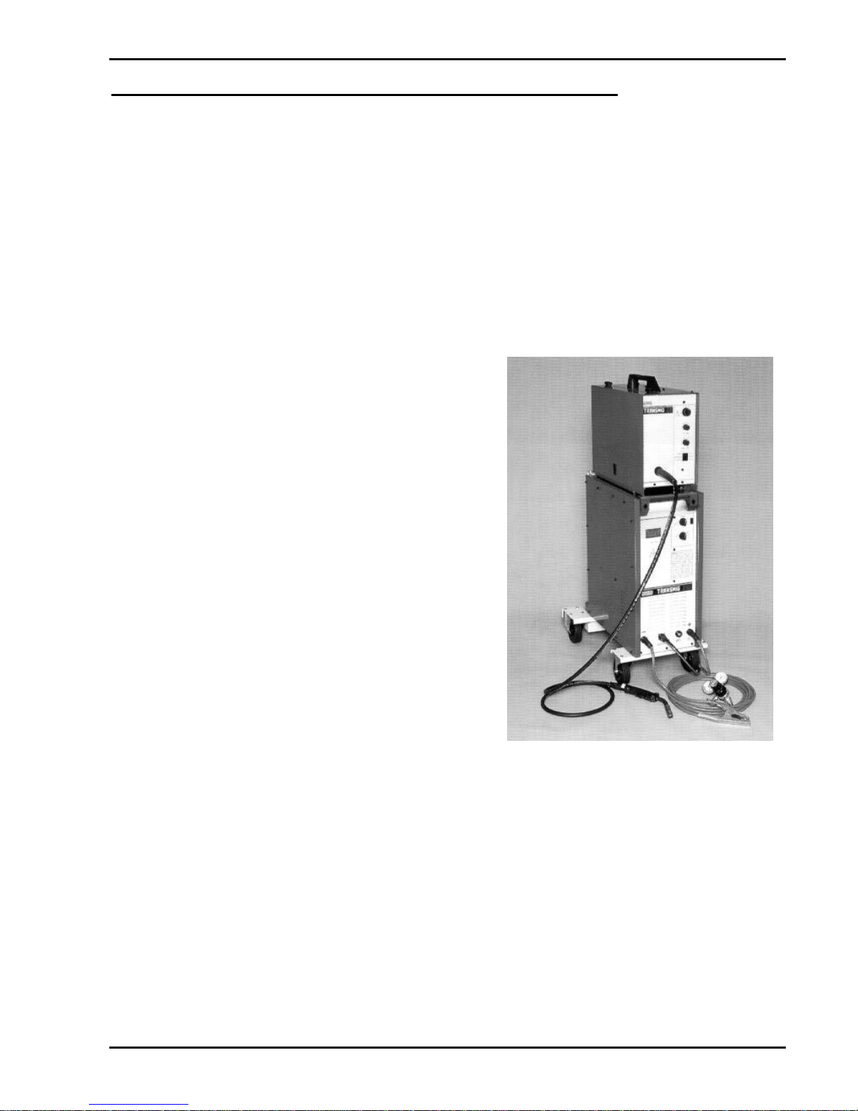
Refer to Figure 5 for the plant setup of a remote Transmig with wirefeeder.
5.1 Power Source Connections
a) Remove all packaging materials.
b) Fit the fixed and swivel wheels to the Power Source. Refer to WARNING 2.
c) Connect the work lead to the negative welding terminal (-) [positive welding terminal (+)
for flux cored wire].
d) Position a gas cylinder on the rear tray and lock securely to the Power Source cylinder
bracket with the chain provided. If this arrangement is not used then ensure that the gas
cylinder is secured to a building pillar, wall bracket or otherwise securely fixed in an
upright position.
e) Fit the gas regulator and Flowmeter to the gas cylinder.
5.2 Wirefeeder Connections
a) Connect the welding power cable to the
positive welding terminal (+) [negative
welding terminal (-) for flux cored wire].
b) Connect the control cable to the front of the
Power Source of the Transmig 210 remote or
Transmig 250 remote or Transmig 330.
c) Connect the gas hose from the rear of the
wire feeder unit to the Flowmeter outlet.
d) Two dual groove feed rollers are supplied as
standard with the plant. These can
accommodate 0.6, 0.8, 0.9, 1.0 and 1.2
diameter hard wires. Select the roller
required with the chosen wire size marking
facing outwards.
e) Fit the electrode wire spool to the wire reel
hub located behind the wire compartment
door. Ensure that the drive dog-pin engages
the mating hole in the wire spool. Push the
'R' clip into place to retain the wire spool
securely. The wire should feed from the
bottom of the spool.
f) Fit the torch to the wire feed unit by releasing the torch locking screw in the brass torch
adaptor and pushing in the torch fitting until the plastic torch casing meets the brass
adaptor. Tighten the torch locking screw securely. Also ensure that the adjacent black
knurled screw in the wire feeder casting is securely tightened. Remove the contact tip from
the torch.
g) Connect the torch trigger lead to the torch trigger terminals.
h) Lift up the wire feeder pressure lever and pass the electrode wire through the inlet guide,
between the rollers, through the outlet guide and into the torch.
i) Lower the pressure lever and with the torch lead reasonably straight, feed the wire through
the torch. Fit the appropriate contact tip. Refer to CAUTION 3.
Figure 5 - Remote Transmig Setup
Page 15
Transmig 210, 250, 310, 330
Page 16 of 31 DOC No: MIGTRN0001
Date: 14/09/98 Issue No: 2
6. Power Source / 2R Wirefeeder Controls, Indicators and Features
WirespeedControl
SpotTimerControl
DwellTimerControl
ModeSelector
Switch
BrassTorchAdaptor
IndicatorLight
On/Off&Coarse
VoltageControlSwitch
FineVoltage
ControlSwitch
NegativeWelding
CurrentTerminal
PositiveWelding
CurrentTerminal
OptionalMeter
(standardontheTransmig330)
TorchPolarityLead
IndicatorLight
On/Off&Coarse
VoltageControlSwitch
FineVoltage
ControlSwitch
NegativeWelding
CurrentTerminal
WirefeederControl
Socket
PositiveWelding
CurrentTerminal
OptionalMeter
(standardontheTransmig330)
Ammeter/Voltmeter
Switch
Figure 6 - Compact Transmig controls Figure 7 - Remote Transmig controls
6.1 Indicator Light
The indicator light is provided to indicate when the Transmig is connected to the Mains supply
voltage.
WARNING 3: When the light is lit, the machine is connected to the Mains supply voltage and
the internal electrical components are at Mains voltage potential.
6.2 Standby/Coarse Voltage Control Switch and Fine Voltage Control Switch
The Coarse Voltage Control switch turns off the fan and auxiliary power in the STANDBY position.
It sets the voltage level to the welding terminals in the remaining positions, increasing the voltage as
it is rotated in the clockwise direction. The Fine Voltage Control switch increases the voltage (in
smaller increments than the Coarse switch) as it is rotated in the clockwise direction.
WARNING 4: The Coarse & Fine Voltage Control switches MUST NOT BE SWITCHED
during the welding process.
Wirespeed
Control
SpotTimer
Control
PowerCable
ControlCable
GasHose
DwellTimer
Control
ModeSelector
Switch
BrassTorch
Adaptor
Figure 8 - Wirefeeder controls
Page 16
Transmig 210, 250, 310, 330
DOC No: MIGTRN0001 Page 17 of 31
Issue No: 2 Date: 14/09/98
6.3 Digital Ammeter and Voltmeter (Standard for Transmig 330 Only)
Where fitted an average reading ammeter and voltmeter is provided to allow accurate monitoring
(5% tolerance) of welding current and voltage. Refer to section 9.1 on page 25 for the Improved
Current Accuracy Calibration Procedure for the Digital Meter.
The Digital Meter will display both welding current and voltage. To toggle between the current and
voltage readings depress the push button switch mounted below the meters display. See Figure 9 for
an example of current and voltage displays.
Value displayed for 157 Amp Value displayed for 23.4 Volts
Figure 9 - Examples of the digital read outs
6.4 Torch Polarity Lead (Compact Models Only)
This lead selects the welding voltage polarity of the electrode wire. Plug it into the positive welding
terminal ( + ) when using steel, stainless steel or aluminium electrode wire. Plug the Torch Polarity
Lead into the negative welding terminal ( - ) when using gasless electrode wire. If in doubt, consult
the manufacturer of the electrode wire for the correct polarity.
6.5 Positive and Negative Welding Terminals
Welding current flows from the Power Source via heavy duty bayonet type terminals. It is essential,
however, that the male plug is inserted and turned securely to achieve a sound electrical connection.
WARNING 5: Loose welding terminal connections can cause overheating and result in the
male plug being fused in the bayonet terminal.
6.6 Wirefeeder Control Socket (Remote Wirefeeder Models Only)
This socket accepts the male plug on the control cable from the Wirefeeder. The male plug should
be fully inserted into the control socket then locked into position by turning the retaining ring on the
male plug in a clockwise direction.
6.7 Thermal Overload
The critical component for thermal protection is the rectifier stack, which is fitted with a thermal
overload cutout device. If the overload operates then the machine should be left to cool for
approximately 15 minutes before resuming welding. There will be no danger of transformer damage
if the Power Source is operated within its duty cycle, refer to section 1.1 for an explain of duty cycle
and section 2 for the Power Source specifications.
Page 17

Transmig 210, 250, 310, 330
Page 18 of 31 DOC No: MIGTRN0001
Date: 14/09/98 Issue No: 2
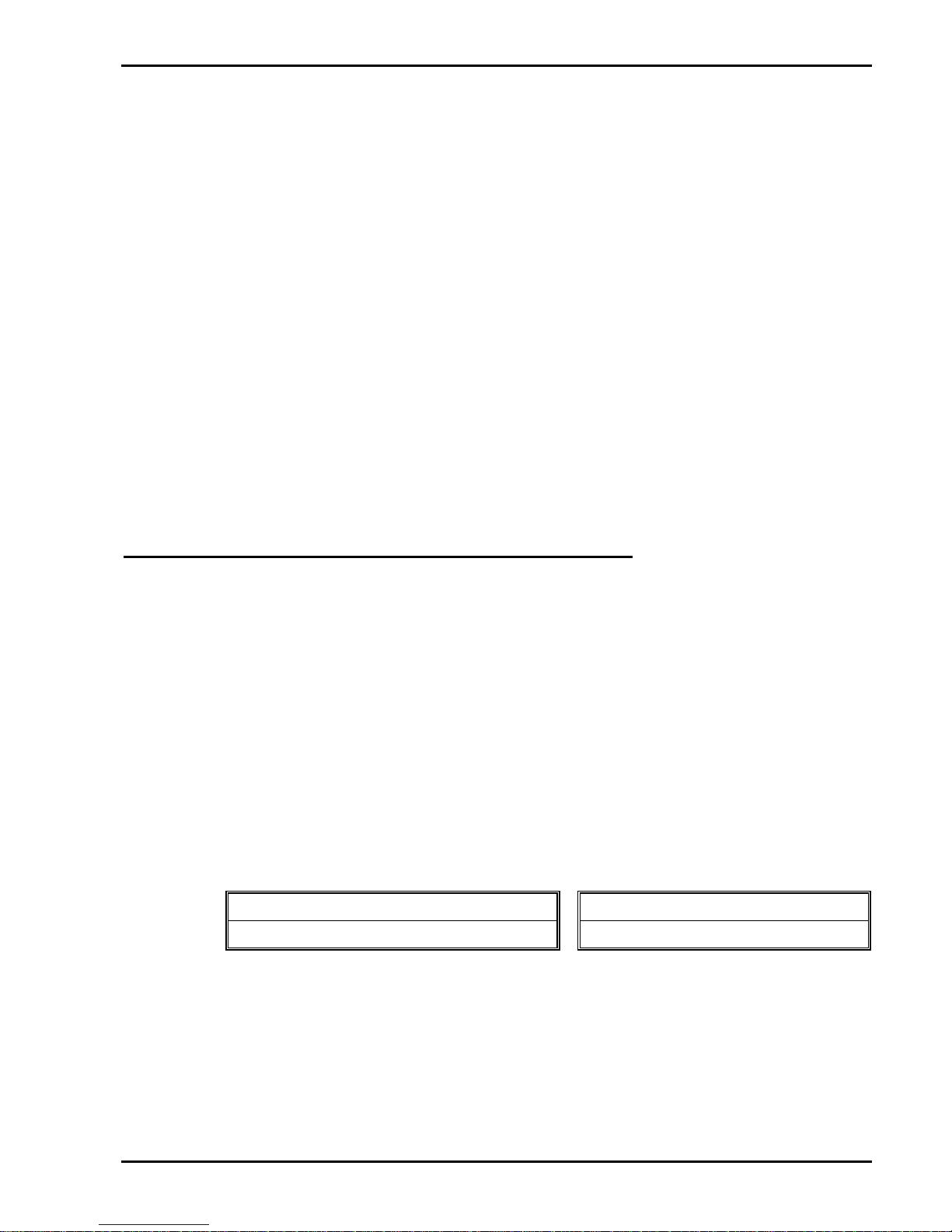
6.8 Choice of Inductance Setting (Transmig 210 & 250 Only)
The Transmig 210 & 250 have two inductance taps. These inductance terminals are the positive
welding terminals. Inductance selection can effect the spatter level and penetration characteristics of
the weld. The correct choice depends upon the shielding gas, transfer mode and the material type.
Used for:
1. CO2 shielded welding.
2. Dip transfer with Æ1.2mm wires (CO2 or mixed gas).
3. Gives a hotter weld in DIP transfer.
Used for:
1. Spray transfer
2. Aluminium and Flux Cored wires.
3. Gives a cooler weld in DIP transfer.
CAUTION 4:If in doubt, use the high inductance setting.
6.9 Wirespeed Control (Compact Models & 2R Wirefeeder Only)
The Wirespeed Control knob controls the welding current via the electrode wire feed rate. ie the
speed of the wire feed motor.
6.10 Spot Timer (Compact Models & 2R Wirefeeder Only)
With the MODE SELECTOR switch is switched to the SPOT position, the SPOT TIME knob
controls the duration of a single spot weld.
With the MODE SELECTOR switch is switched to the STITCH position, the SPOT TIME knob
controls the welding or 'ON' time whilst stitch welding.
6.11 Dwell Timer (Compact Models & 2R Wirefeeder Only)
The DWELL TIME knob controls the interval or 'OFF' time whilst stitch welding.
6.12 Mode Selector Switch (Compact Models & 2R Wirefeeder Only)
The Mode Selector switch selects the method of welding mode.
a) SPOT
This mode of welding is used to weld two plates together at a desired
location by melting the top & bottom plates together to form a nugget
between them. The spot time period is set by the SPOT TIME control
knob. Refer to CAUTION 5.
CAUTION 5:A spot nozzle (P/N
EL22I62FAS) should be used on the MIG torch to obtain
consistent spot welds.
b) CONTINUOUS
This mode of welding is used to weld two or more components together
with a continuous weld.
c) STITCH
This mode of welding is used to weld two or more components together
with a stitch weld. The SPOT TIME knob controls the welding or 'ON'
time whilst the DWELL TIME knob controls the interval or 'OFF' time
for stitch welding.
6.13 Burnback Control (Compact Models & 2R Wirefeeder Only)
The amount of electrode wire that is burnt back out of the weld pool, when the torch trigger switch
is released, can be adjusted by the potentiometer shaft that is located inside the wire spool cavity
compartment above the wire feed motor.
High Inductance Symbol
Low Inductance Symbol
Page 18
Transmig 210, 250, 310, 330
DOC No: MIGTRN0001 Page 19 of 31
Issue No: 2 Date: 14/09/98
6.14 Wirefeeder Driver Roller Pressure Adjustment (Compact Models & 2R
Wirefeeder Only)
The moveable roller applies pressure to the grooved roller via screw adjustable spring pressure. The
adjustable spring screw should be adjusted to a minimum pressure that will provide satisfactory wire
feed without slippage. If slipping occurs, and inspection of the wire contact tip reveals no wear,
distortion or burn-back jam, the correct feed roll groove size is used, the feed roll groove is not
worn, the conduit liner should be checked for kinks and clogging by metal flakes and swarf. If this is
not the cause of slipping, the feedroll pressure can be increased by rotating the adjustable spring
screw clockwise. Excessive pressure may cause rapid wear of the feed roller, motor shaft and motor
bearings. Refer to CAUTION 7.
6.15 Wire Reel Brake (Compact Models & 2R Wirefeeder Only)
The wire reel hub incorporates a friction brake which is adjusted during manufacture for optimum
braking. If it is considered necessary, adjustment can be made by turning the large nut inside the
open end of the wire reel hub. Clockwise rotation will tighten the brake. Correct adjustment will
result in the reel circumference continuing no further than 20mm after release of the Torch trigger
switch. The electrode wire should be slack without becoming dislodged from the reel.
CAUTION 6: Excessive tension on the brake will cause rapid wear of mechanical wire feed
parts, overheating of electrical componentry and possibly an increased incidence
of wire Burnback into the contact tip.
7. TWECO MIG TORCH (P/N 717578 where supplied)
7.1 Introduction
The TWECO 250A gun fitted to the Transmig offers robust construction, unparalleled reliability and
easy replacement of consumable parts. The TWECO 250A has an operating capacity in excess of
the capacity of the Transmigs and can be expected to give trouble free service.
TWECO MIG Torches may be fitted to many different types of MIG welding plants so that your
whole shop can be converted to TWECO. Not only will this give greater reliability (and hence
greater productivity), but it will reduce stockholdings of consumable parts. See your CIGWELD
distributor for details.
CAUTION 7:Genuine TWECO contact tips and lines should be used. Many non-genuine liners
use inferior materials which can cause wire feed problems.
7.2 Torch Consumable Parts
NOTE 1: * denotes parts that are supplied as standard with MIG torch 717578.
a) Gas Diffusers
Part No. Part No.
* EL52 (slide on nozzles) EL52CT (screw on nozzles)
Table 3 - MIG torch gas diffusers
Page 19
Transmig 210, 250, 310, 330
Page 20 of 31 DOC No: MIGTRN0001
Date: 14/09/98 Issue No: 2
b) Contact Tips
STANDARD TAPERED
Wire Size
(mm)
Part No. Wire Size (mm) Part No.
0.6 not available 0.6 EL16T23
0.8 EL1630 0.8 EL16T30
0.9 * EL1635 0.9 EL16T35
1.0 EL1640 1.0 EL16T40
1.2 EL1645 1.2 EL16T45
1.2 Alum EL16A364 1.2 Alum EL16AT364
Table 4 - MIG torch contact tips
c) Nozzles
Bore Size
(mm)
Part No. Bore Size (mm) Part No.
9.5 EL22A37 9.5 EL22CT37
9.5 EL22A37F 9.5 EL22CT37F
12.7 EL22A50 12.7 EL22CT50
12.7 EL22A50F 12.7 EL22CT50F
12.7 EL22I50P 12.7 EL22CT50P
15.9 EL22A62 15.9 EL22CT62
15.9 EL22A62F 15.9 EL22CT62F
15.9 * EL22I62P 15.9 EL22CT62P
19.1 EL22A75 19.1 EL22CT75
19.1 EL22A75F 19.1 EL22CT75F
15.9 EL22I62FAS (Spot Nozzle)
CT = Coarse Thread
F = Flush Tip
P=Protruding Tip
Table 5 - MIG torch nozzles
d) Conduit liners
HARD ELECTRODE WIRE SOFT ELECTRODE WIRE
Wire Size Part No. Wire Size (mm) Part No.
0.6 OTW42/23 0.6 Alum not available
0.8 OTW42/3035 0.8 Alum not available
0.9 * OTW42/3035 0.9 Alum OTW42N/3545
1.0 OTW42/4045 or OTW44/3545 1.0 Alum or
1.2 OTW42/4045 or OTW44/3545 1.2 Alum OTW44N/3545
Table 6 - MIG torch conduit liners
Page 20
Transmig 210, 250, 310, 330
DOC No: MIGTRN0001 Page 21 of 31
Issue No: 2 Date: 14/09/98
7.3 MIG Torch Components
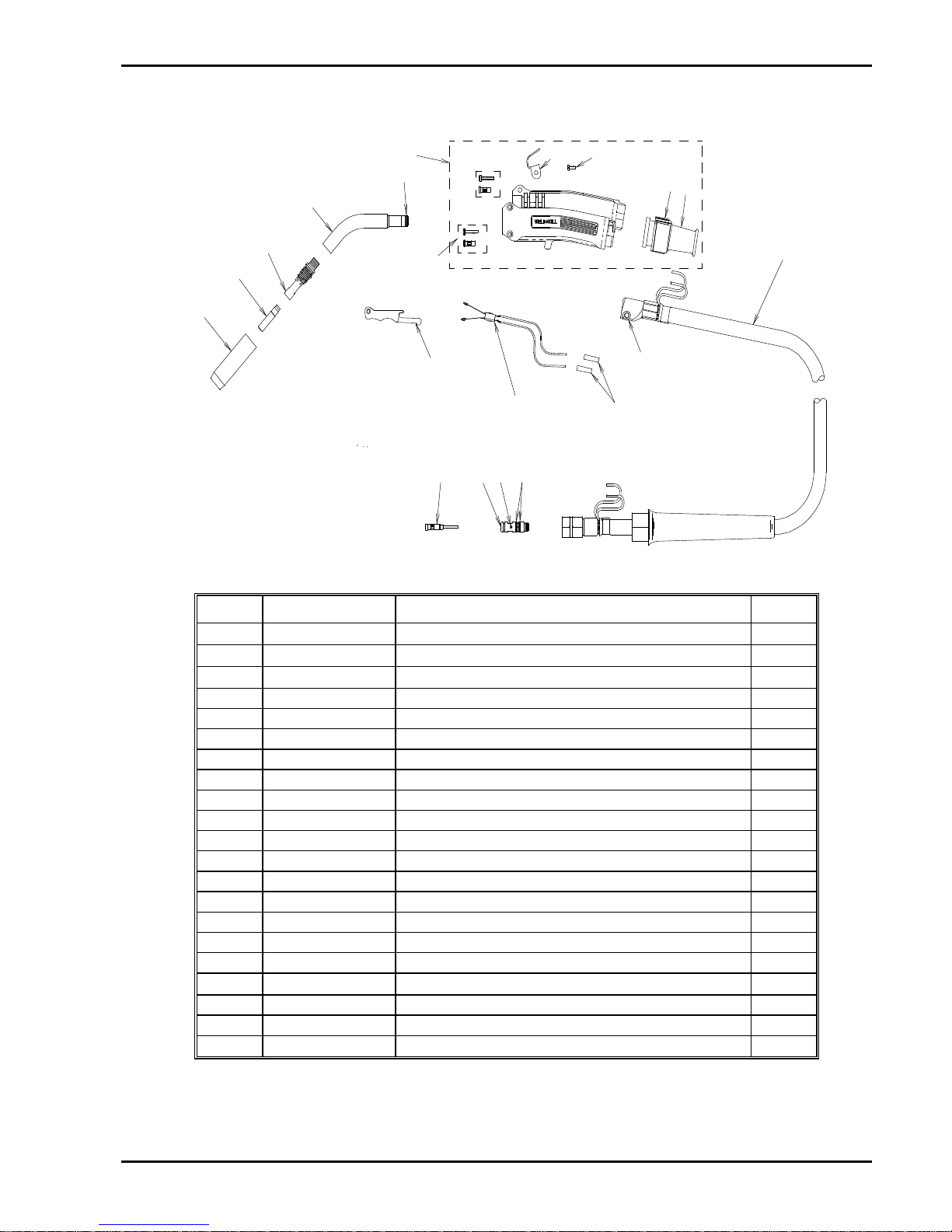
Refer to Figure 10 for a pictorial representation of the components listed in Table 7.
1
2
3
4
5
6
7
22
23
8
14
9
13
12
10
11
18
17 1516
Figure 10 - Exploded view of MIG torch
Item Part No. Description Qty
1
¾
Nozzle (refer to Table 5)
1
2
¾
Contact tip (refer to Table 4)
1
3
¾
Gas diffuser (refer to Table 3)
1
4 WM6345 Conductor tube 1
5 OTW45B O-Ring, Gun Handle 1
6 OTW90721H Handle kit (includes items 7, 22 & 23) 1
7
Insert & screw (refer to item 6) 2
8 n/a Handle cap 1
9
n/a
Support 1
10 ELC94 Trigger Lever 1
11 ELC94B Trigger blades 1
12
¾
Butt Splice (insulated crimp link 1.5mm2 ) 2
13 ELC1042 Cap screw 1
14 OTW9072110 Cable assembly 1
15 OTW224 O-Ring, Connector Plug 2
16 OTW44C Set screw 8/32 UNC 1
17 OTW350174 Connector plug 1
18
¾
Conduit liner (refer to Table 6)
1
22
¾
Gun hanger (refer to item 6) 1
23
¾
Hanger screw (refer to item 6) 1
24 ELC94L Locking Trigger (not shown) (option)
Table 7 - MIG Torch components
Page 21
Transmig 210, 250, 310, 330
Page 22 of 31 DOC No: MIGTRN0001
Date: 14/09/98 Issue No: 2
7.4 Installing A New Conduit Liner
a) Be sure the MIG Torch cable is arranged in a straight line, free from twists, when installing
or removing a conduit liner. Remove the old conduit liner by first removing the MIG
Torches nozzle, contact tip and gas diffuser. Then loosen set screws (8/32 UNC) in the
conductor tube and connector plug and pull the old conduit liner out of the cable assembly
from the connector plug end.
b) To install a new conduit liner, first inspect the o-ring gas seal on the conduit liner for cuts
or damage. Start from the connector plug end of the assembly and begin pushing the
conduit liner through the connector plug, cable assembly and into the gun. If the conduit
liner should lodge along the way, gently whip or work the cable assembly to aid forward
movement.
c) When the conduit liner stop meets the end of the connector plug and the new raw end
extends through the end to the conductor tube, the Allen screw in the connector plug must
be securely tightened onto the conduit liner to prevent its backward movement.
IMPORTANT 1: When the conduit liner is fully inserted into the cable assembly and the conduit
liner stop is firmly against the Connector Plug, the "raw end" of the conduit
liner will protrude out of the open end of the gun conductor tube. Trim the
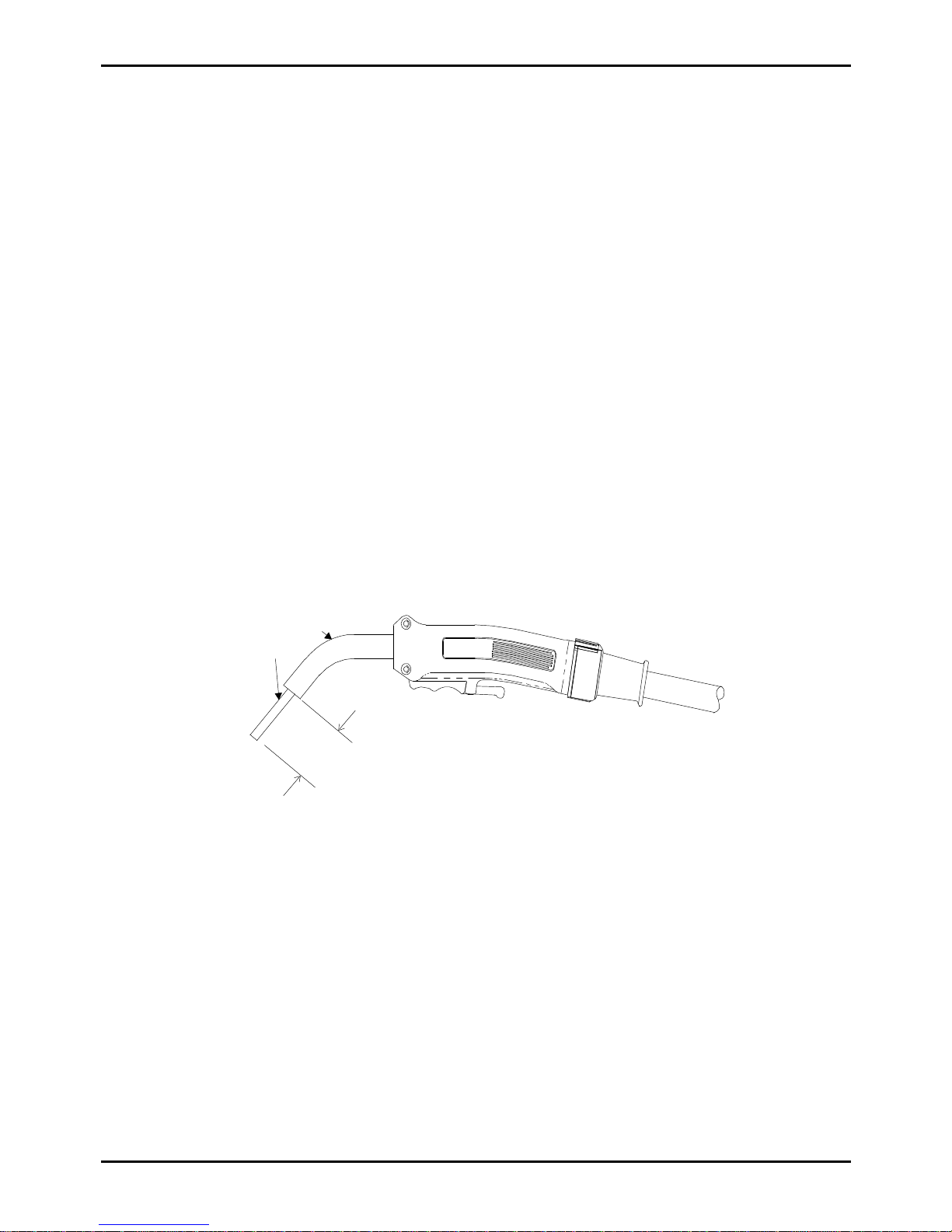
conduit liner as shown in Figure 11. The trimmed end which seats in the Gas
Diffuser must be filed and reamed smooth on the inside and outside radii so the
electrode wire will not be obstructed.
d) Replace Gas Diffuser, Contact Tip, and Nozzle.
e) Tighten the Allen screw in the conductor tube.
WARNING 6: Do not over tighten the conductor tube screw as this action will result in the
distortion of the conduit liner and will lead to wire feedability problems.
34mm
(1.34")
Conductortube
Conduit
Figure 11 - Conduit liner trim length
7.5 MIG Torch Maintenance
Remove dust and metallic particles from the torch conduit liner by forcing clean, dry compressed air
into the conduit liner once a week. This will minimise wire feeding problems.
Page 22
Transmig 210, 250, 310, 330
DOC No: MIGTRN0001 Page 23 of 31
Issue No: 2 Date: 14/09/98
8. BASIC WELDING TECHNIQUE
8.1 Setting of the Power Source & Wirefeeder
The setting of the Transmig requires some practice by the operator, the welding plant having two
control settings that have to balance. These are the Wirespeed control and the welding Voltage
Control switches. The welding current is determined by the Wirespeed control, the current will
increase with increased Wirespeed, resulting in a shorter arc. Less wire speed will reduce the current
and lengthen the arc. Increasing the welding voltage hardly alters the current level, but lengthens the
arc. By decreasing the voltage, a shorter arc is obtained with a little change in current level.
When changing to a different electrode wire diameter, different control settings are required. A
thinner electrode wire needs more Wirespeed to achieve the same current level.
A satisfactory weld cannot be obtained if the Wirespeed and Voltage control switch settings are not
adjusted to suit the electrode wire diameter and the dimensions of the work piece.
If the Wirespeed is too high for the welding voltage, “stubbing” will occur as the wire dips into the
molten pool and does not melt. Welding in these conditions normally produces a poor weld due to
lack of fusion. If, however, the welding voltage is too high, large drops will form on the end of the
wire, causing spatter. The correct setting of voltage and Wirespeed can be seen in the shape of the
weld deposit and heard by a smooth regular arc sound.
8.2 Position of MIG Torch
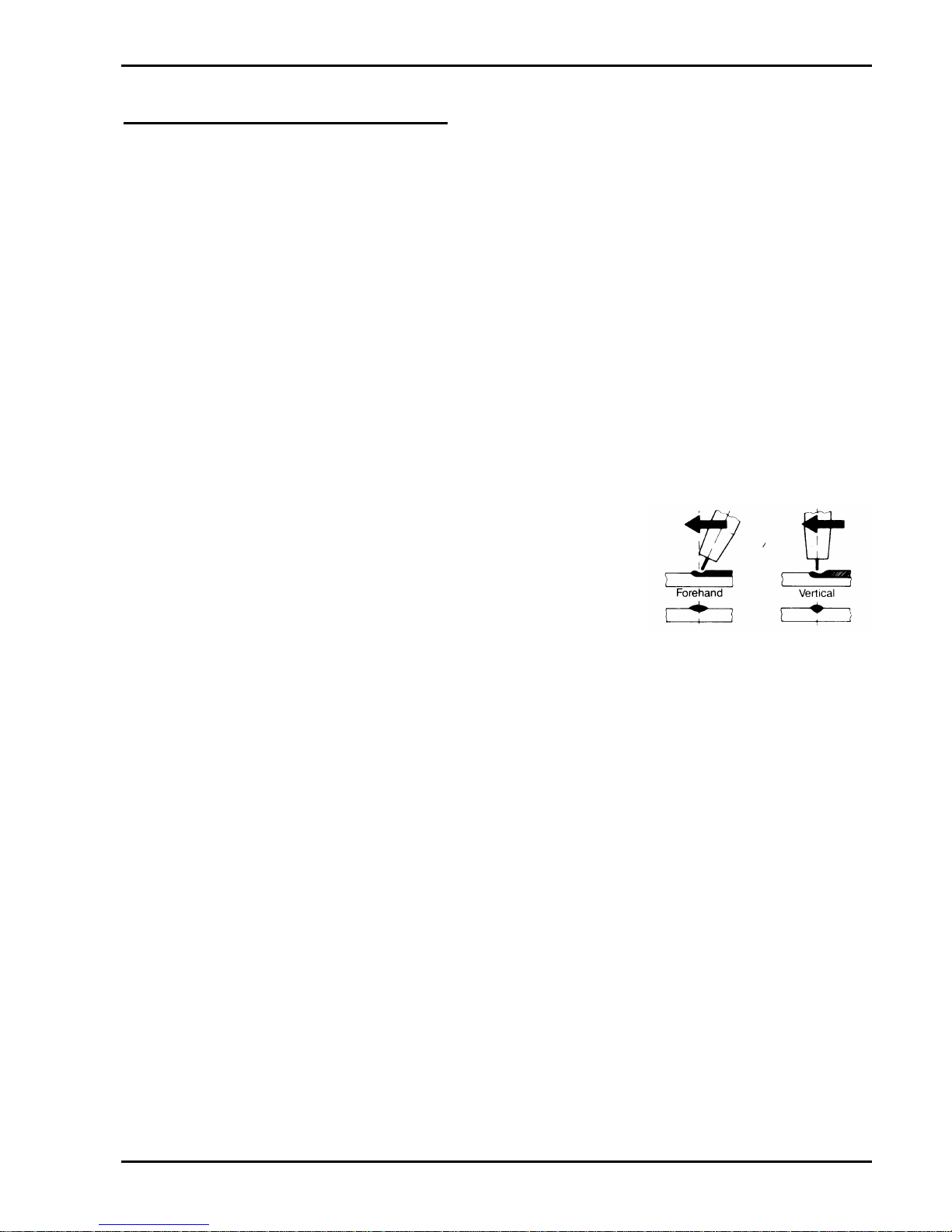
The angle of MIG torch to the weld has an effect on the width of
the weld run. Refer to Figure 12.
8.3 Distance from the MIG Torch Nozzle to the Work
Piece
The electrode wire stick out from the MIG Torch nozzle should
be between 2.0mm to 5.0mm. This distance may vary depending on the type of joint that is being
welded.
8.4 Travel Speed
Speed at which a weld travels influences the width of the weld and penetration of the welding run.
8.5 Stitch Welding Operation
Stitch welding is normally used to bridge excessive gaps between panels or when welding very thin
material to prevent heat build up and distortion. Set the controls as follows for stitch welding:
a) Coarse & Fine Voltage Control Switches and Wirespeed Control
Set these controls to obtain the desired welding conditions for the wire and material being
welded.
b) Mode Selector Switch
Set the MODE SELECTOR switch to STITCH.
c) Spot Time
Adjust the SPOT TIME control knob for the desired weld or 'ON' time whilst stitch welding.
d) Dwell Time
Adjust the DWELL TIME control knob for the desired interval or 'OFF' time whilst stitch
welding.
Figure 12 - MIG Torch angle
Page 23

Transmig 210, 250, 310, 330
Page 24 of 31 DOC No: MIGTRN0001
Date: 14/09/98 Issue No: 2
8.6 Spot Welding Operation
Fit a spot welding nozzle to the MIG Torch for consistent spot welding operations. The Transmigs
will operate effectively using 0.8mm electrode wire when spot welding. Penetration depth is limited
when using 0.6mm electrode wire for spot welding. Set the controls as follows for spot welding:
a) Coarse & Fine Voltage Control Switches and Wirespeed Control
Select higher Voltage Control switch positions and set the Wirespeed Control between 9 to 15
m/min for maximum penetration.
b) Mode Selector Switch
Set the MODE SELECTOR switch to SPOT.
c) Spot Time
Adjust the SPOT TIME control knob for the desired weld or 'ON' time for spot welding.
d) Dwell Time
The DWELL TIME control knob has no affect in this mode of operation.
9. ROUTINE MAINTENANCE & INSPECTION
The only routine maintenance required for the Transmig is a thorough cleaning and inspection. For
operating environments with high levels of air born metallic dust particles clean out the Power
Source/Wirefeeder once a week. For operating environments with low levels of air born metallic dust
particles clean out the Power Source/Wirefeeder once every six months.
WARNING 7: Disconnect the Transmig from the Mains supply voltage before disassembling.
Special maintenance is not necessary for the control unit parts in the Power Source / Wirefeeder. If these
parts are damaged for any reason, replacement is recommended.
CAUTION 8: Do not blow air into the Power Source / Wirefeeder during cleaning. Blowing
air into the Power Source / Wirefeeder can cause metal particles to interfere with
sensitive electronic components and cause damage to the Power Source /
Wirefeeder.
To clean the Power Source / Wirefeeder, disconnect the Power Source from the Mains supply voltage,
remove the covers and use a vacuum cleaner to remove any accumulated dust. The Power Source /
Wirefeeder should also be wiped clean. If necessary, solvents that are recommended for cleaning electrical
apparatus may be used.
Troubleshooting and repairing the Transmig should be carried out only by those who are familiar with
electrical equipment.
WARNING 8: Do not attempt to diagnose or repair unless you have had training in electronic
measurement and troubleshooting techniques.
Page 24

Transmig 210, 250, 310, 330
DOC No: MIGTRN0001 Page 25 of 31
Issue No: 2 Date: 14/09/98
9.1 Improved Current Accuracy Calibration Procedure for the Digital Meter
CAUTION 9: This calibration procedure should be carried out by a qualified electrical
tradesperson.
The following procedure will give a current measurement accuracy of better than the factory
standard of approximately 5%.
a) Equipment Required:
Transmig
210
Transmig
250
Transmig
310
Transmig
330
DC Ammeter
(certified up to ±1%
accuracy)
250A 300A 400A 400A
LOAD RESISTANCE of
0.1W
5kW 8kW 12kW 12kW
Output Connecting Leads
4 4 4 4
b) Procedure:
i) With the Transmig switched off, connect the LOAD RESISTANCE and DC
AMMETER to the output terminals.
ii) Open the wirefeeder compartment door or remove the lefthand side cover (when
viewing the Transmig from the front) from the Power Source.
iii) Select maximum voltage switch positions Coarse 4 Fine 4(MIG 210/250)
Coarse 4 Fine 6(MIG 310/330)
iv) Switch the Mains supply voltage to the Transmig ON.
v) Ensure the DIGITAL METER is selected to read current.
vi) Short circuit the TORCH TRIGGER terminals to energise output welding terminals.
CAUTION 10: Do not allow the Transmig to remain ON under load for more than ONE
minute!
vii) Determine the output current as given by the DC AMMETER.
viii) Adjust SHUNT CAL. potentiometer on DIGITAL METER to read identically with
DC AMMETER.
ix) Open circuit the TORCH TRIGGER terminals to deactivate output welding
terminals.
x) Select minimum voltage switch positions Coarse 1 Fine 1
xi) Short circuit the TORCH TRIGGER terminals to energise output welding terminals.
Refer to CAUTION 10.
xii) Determine output current as given by the DC AMMETER.
xiii) Confirm the minimum DIGITAL METER reading is within ±2% of DC AMMETER.
xiv) If the above is not met, offset the SHUNT CAL. potentiometer such that both the
minimum and maximum values are within ±2%.
xv) The improved accuracy for DIGITAL METER is now complete.
xvi) Where fitted, position the meter cover over the hexagonal brass spacers taking care
not to trap loom wiring.
xvii) Fit the M3 flat washers and M3x10 screws through the meter cover and into the
hexagonal brass spacers.
Page 25

Transmig 210, 250, 310, 330
Page 26 of 31 DOC No: MIGTRN0001
Date: 14/09/98 Issue No: 2
xviii) Close wire-feeder compartment or replace side panel.
10. BASIC TROUBLESHOOTING
The basic level of troubleshooting is that which can be performed without special equipment or knowledge,
and without removing the covers from the Power Source / Wirefeeder.
If major components are faulty, then the Power Source / Wirefeeder should be returned to an Accredited
CIGWELD Service Agent for repair.
10.1 Solving Problems Beyond the Welding Terminals
The general approach to fix Gas Metal Arc Welding (GMAW) problems is to start at the wire spool
then work through to the MIG torch. There are two main areas where problems occur with
GMAW:
a) Porosity
When there is a gas problem the result is usually porosity within the weld metal. Porosity
always stems from some contaminant within the molten weld pool which is in the process of
escaping during solidification of the molten metal.
Contaminants range from no gas around the welding arc to dirt on the work piece surface.
Porosity can be reduced by checking the following points.
1. Gas cylinder contents and flow meter. -Ensure that the gas cylinder is not empty and the
flow meter is correctly adjusted to 15 litres per
minute.
2. Gas leaks. -Check for gas leaks between the regulator/cylinder
connection and in the gas hose to the Power
Source.
3. Internal gas hose in the Power Source. -Ensure the hose from the solenoid valve to the
torch adaptor has not fractured and that it is
connected to the torch adaptor.
4. Welding in a windy environment. -Shield the weld area from the wind or increase the
gas flow.
5. Welding dirty, oily, painted, oxidised or
greasy plate.
-Clean contaminates off the work piece.
6. Distance between the MIG torch nozzle
and the work piece.
-Keep the distance between the MIG torch nozzle
and the work piece to a minimum. Refer to section
8.3 on page 23.
7. Maintain the MIG torch in good working
order.
-Ensure that the gas holes are not blocked and gas
is exiting out of the torch nozzle. Refer to
CAUTION 11.
Do not restrict gas flow by allowing spatter to
build up inside the torch nozzle.
Check that the MIG torch O-rings are not
damaged.
CAUTION 11: Disengage the drive roll when testing for gas flow by ear.
Page 26

Transmig 210, 250, 310, 330
DOC No: MIGTRN0001 Page 27 of 31
Issue No: 2 Date: 14/09/98
b) Inconsistent wire feed
Wire feeding problems can be reduced by checking the following points.
1. Wire spool brake is too tight -Feed roller driven by motor in the cabinet will
slip.
2. Wire spool brake is too loose -Wire spool can unwind and tangle.
3. Worn or incorrect feed roller size -Use 'U' groove drive feed roller matched to the
aluminium wire size you are welding.
Use 'V' groove drive feed roller matched to the
steel wire size you are welding.
Use ‘knurled V’ groove drive feed roller matched
to the flux cored wire size you are welding.
4. Mis-alignment of inlet/outlet guides -Wire will rub against the mis-aligned guides and
reduces wire feedability.
5. Liner blocked with swarf -Increased amounts of swarf is produced by the
electrode wire passing through the feed roller
when excessive pressure is applied to the
pressure roller adjuster.
Swarf can also be produced by the wire passing
through an incorrect feed roller groove shape or
size.
Swarf is fed into the conduit liner where it
accumulates thus reducing wire feedability.
6. Incorrect or worn contact tip -The contact tip transfers the weld current to the
electrode wire. If the hole in the contact tip is too
large then arcing may occur inside the contact tip
resulting in the wire jamming in the contact tip.
When using soft wire such as aluminium it may
become jammed in the contact tip due to
expansion of the wire when heated. A contact tip
designed for soft wires should be used.
7. Poor work lead contact to work piece -If the work lead has a poor electrical contact to
the work piece then the connection point will heat
up and result in a reduction of power at the arc.
8. Bent liner -This will cause friction between the wire and the
liner thus reducing wire feedability
Page 27

Transmig 210, 250, 310, 330
Page 28 of 31 DOC No: MIGTRN0001
Date: 14/09/98 Issue No: 2
10.2 Welding Problems
FAULT CAUSE REMEDY
1 Undercut AWelding arc voltage too
high.
AReduce voltage by reducing the
Voltage Control switches positions or turn the Wirespeed con-
trol knob clockwise.
BIncorrect torch angle BAdjust angle
CExcessive heat input CIncrease the torch travel speed or
reduce welding current by
reducing the Voltage Control
switches positions and turn the
Wirespeed control knob anti-
clockwise.
2 Lack of penetration AWelding current too low AIncrease welding current by
increasing turn the Wirespeed
control knob clockwise and
increasing Voltage Control
switch positions.
BJoint preparation too
narrow or gap too tight
BIncrease joint angle or gap
CShielding gas incorrect CChange to a gas which gives
higher penetration
3 Lack of fusion Arc voltage to low Increase Arc voltage by
increasing the Voltage Control
switches position.
4 Excessive spatter AArc voltage too high ALower voltage by reducing the
Voltage Control switches
positions or turn the Wirespeed
control knob clockwise.
BArc voltage too low BRaise voltage by increasing the
Voltage Control switches or turn
the Wirespeed control knob anti-
clockwise.
5 Irregular weld shape AIncorrect voltage and
current settings. Convex,
Arc voltage too low
Concave,
voltage too high.
AAdjust voltage and current by
adjusting the Voltage Control
switches positions and the
Wirespeed control knob.
BWire is wandering BReplace contact tip
CIncorrect shielding gas CCheck gas selection
DInsufficient or excessive
heat input
DAdjust the Wirespeed control
knob or the Voltage Control
switches.
6 Arc does not have a crisp
sound that short arc
exhibits when the wirefeed
speed and voltage are
adjusted correctly.
The MIG torch has been
connected to the wrong
voltage polarity on the front
panel.
Connect the MIG torch to the
positive welding terminal (+) for
solid wires and gas shielded flux
cored wires.
Page 28

Transmig 210, 250, 310, 330
DOC No: MIGTRN0001 Page 29 of 31
Issue No: 2 Date: 14/09/98
Welding Problems (continued)
FAULT CAUSE REMEDY
7 Weld cracking AWeld beads too small ADecrease torch travel speed
BWeld penetration narrow
and deep
BReduce current and voltage and
increase the MIG Torch travel
speed or select a lower
penetration shielding gas.
CExcessive weld stresses CIncrease weld metal strength or
revise design
DExcessive voltage DDecrease voltage by reducing the
Voltage Control switches.
ECooling rate too fast ESlow the cooling rate by
preheating part to be welded or
cool slowly.
8 Cold weld puddle AFaulty rectifier unit AHave an Accredited CIGWELD
Service Agent test then replace
the faulty component.
BLoss of a phase in the
Mains supply voltage.
BCheck mains power
CLoose welding cable
connection.
CCheck all welding cable
connections.
DLow Mains supply voltage DContact supply authority
10.3 Power Source Problems
FAULT CAUSE REMEDY
1 Indicator light is ON but
welding arc can not be
established.
Coarse Voltage Control
switch is in the STANDBY
position.
Switch the Coarse Voltage
Control switch to a welding
setting.
2 Mains supply voltage is
ON. Indicator light is not lit
and welding arc can not be
established.
ABPrimary fuse is blown.
Broken connection in
primary circuit.
ABReplace primary fuse.
Have an Accredited CIGWELD
Service Agent check primary
circuit.
3 Mains indicator light is not
lit but welding arc can be
established.
Burnt out Indicator light. Have an Accredited CIGWELD
Service Agent replace Indicator
light.
4 Mains supply voltage is
ON and Indicator light is lit
but when the torch trigger
switch is depressed nothing
happens.
Torch trigger switch leads
are disconnected.
Reconnect.
5 Mains supply voltage is
ON, no wire feed but gas
flows from the MIG Torch
when the torch trigger
switch is depressed.
AElectrode wire stuck in
conduit liner or contact tip
(burn-back jam).
ACheck for clogged / kinked MIG
Torch conduit liner or worn
contract tip. Replace faulty
components.
BFaulty control PCB BHave an Accredited CIGWELD
Service Agent investigate the
fault.
Page 29

Transmig 210, 250, 310, 330
Page 30 of 31 DOC No: MIGTRN0001
Date: 14/09/98 Issue No: 2
Power Source Problems (continued)
FAULT CAUSE REMEDY
6 Wire feeds when the torch
trigger switch is depressed
but arc can not be
established.
Poor or no work lead
contact.
Clean work clamp area and
ensure good electrical contact.
7 Mains supply voltage is
ON and contactor in the
Power Source operates but
wire does not feed when the
torch trigger switch is
depressed.
TWECO Torch has been
damaged internally, trigger
wires are making contact
with welding power cable.
Have an Accredited CIGWELD
Service Agent repair torch &
replace PCB.
8 Jerky wire feed AWorn or dirty contact tip AReplace
BWorn feed roll. BReplace
CExcessive back tension
from wire reel hub.
CReduce brake tension on spool
hub
DWorn, kinked or dirty
conduit liner
DClean or replace conduit liner
9 No gas flow AGas hose is cut. AReplace or repair.
BGas passage contains
impurities.
BDisconnect gas hose from the
rear of Power Source or wire-
feeder then raise gas pressure
and blow out impurities.
CGas regulator turned off. CTurn on.
10Gas flow continues after
the torch trigger switch has
been released.
Gas valve has jammed open
due to impurities in the gas
or the gas line.
Have an Accredited CIGWELD
Service Agent repair or replace
gas valve.
Page 30

Transmig 210, 250, 310, 330
DOC No: MIGTRN0001 Page 31 of 31
Issue No: 2 Date: 14/09/98
10.4 Key Spare Parts
Description Transmig 210 Transmig 250 Transmig 310 Transmig 330
Main Transformer 705164 705165 704983 705166
Auxiliary Transformer 705275 705278 705126 705126
Rectifier 7977657 7977657 7977658 7977658
Capacitor 22000µF 63V
7977178 7977178
¾ ¾
Control PCB (704882) 705150 705150 705150 705150
Contactor 7977752 7977752 7977752 7977752
Wirespeed Knob 7977709 7977709 7977709 7977709
Spot & Dwell Knob 7977708 7977708 7977708 7977708
Wirespeed Potentiometer 704807 704807 704807 704807
Spot & Dwell Potentiometer 704806 704806 704806 704806
Coarse Voltage Switch 7977677 7977678 7977667 7977667
Fine Voltage Switch 7977665 7977666 7977668 7977668
Solenoid Valve KK281 KK281 KK281 KK281
Wire Reel Lock Pin OTWAK1P OTWAK1P OTWAK1P OTWAK1P
Wire Reel Hub 702337 702337 702337 702337
Indicator Light 7977680 7977680 7977681 7977681
Welding Current Terminals 7977159 7977159 704460 704460
Work Lead Plug 705152 705152 704461 704461
Wire Drive Assembly 7977659 7977659 7977659 7977659
Wire Drive Motor 7977693 7977693 7977693 7977693
Two roll wire drive system 7977684 7977684 7977684 7977684
Fan Motor 7976341 7976341 7977679 7977679
Fan Impellor 7977288 7977288 7977288 7977288
Swivel Wheel 7977566 7977566 7977566 7977566
Fixed Wheel 7977567 7977567 7977567 7977567
7 Pin Control Plug 7977162 7977162 7977162 7977162
7 Pin Plug Cable Clamp 703255 703255 703255 703255
7 Pin Control Socket 7977163 7977163 7977163 7977163
Roll on cylinder carrier 704961 704961 704961 704961
Cylinder bracket 704692 704692 704692 704692
Cylinder chain 703625 703625 703625 703625
Front wheel bracket 704960 704960 704960 704960
Wirefeeder to suit Remote Power
Source only
704975 704975
¾
704841
Regulator/Flowmeter 301526 301526 301526 301526
MIG Torch 250A 717578 717578 717578 717578
 Loading...