

Page 1
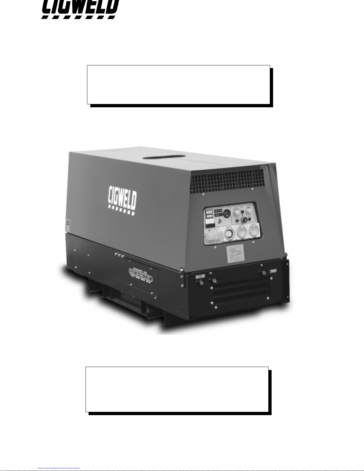
ENGINE DRIVEN WELDER
GENERATING SET
MPM 20/600 I-PS
(Part Number 636806)
DOC No: EDW0007 Date: 16-July-97
Issue No: 2
Page 2
GENERAL USE INSTRUCTIONS
Read the in structions carefully; proceed according to the regulations in use in t he
country where the machine will operate.
TRANSPORTATION
Y
The machine must be fixed securely to t he motor vehicle if it has to be moved to t he
place of use. Raise the machine using the lifting eye if the model provides it;
o the rwise , lift it u sing a fo rk lift, ta king ca re t hat t he we ight is w ell bala nced on t he
two forks. Keep well clear during these operat ions; furthermore, we suggest not t o
keep the machine suspended for long.
Y
If the machine is mounted on a wheels trolley or trailer, be sure the machine is stable
and secure before use.
CAUTION
Y
Note: The generating set or the welder is furnished WITHOUT lubricating oil.
Provide the machine with "10 W 40" multi-grade oil indicated for temperatures
from - 20°C to 40° C in the quantity indicated in the engine SPECIFICATION
section.
Y
Note: If the mach ine is fitte d with a water c ooled engine fill the radiat or circuit with a
solution made up by 50% water and 50% antifreeze liquid in the quantity indicated in
the engine SPECIFICATION section.
Y
Note: T he gen e r a tin g s e t is fur nis h e d w ith a fla t ba tte r y a n d w ithou t a c id . Fill it u s in g
sulphuric acid in a 30% - 40% concentrated solution to cover t he elements. During
this operation, we suggest the operat or use prot ective gloves and goggles; accidental
skin contact with the sulphuric acid solut ion must be washed up immediat ely with
cold water and, if necessary, a doctor must be consulted.
Y
Note: Do not disconnect battery cables when the engine runs. This could result in
serious damage to the machine.
Y
Note: BEFORE OPERATING THE MACHINE the neutral, or the equivalent
winding point, MUST be connected effectively to earth using an earth stake (without
any switch or other device that may interrupt the electrical connection) from the earth
stud available on the machine, and identified by the symbol:
Y
Y
Note: for normal transportation, follow the instructions as specified in the
TRANSPORTATION section.
1
Page 3
RUNNING IN
For the first 50 hours of operation of the machine do not employ more than 70% of the
maximum power indicated in the technical specifications.
STARTING AND WORKING
1- Make the earth connection (see the USE INSTRUCTIONS).
2- If the machine model IS NOT equipped with a earth leakage circuit breaker the
available socket is intended ONLY for connecting the machine to a switchboard
equipped with all protection devices imposed by current law regulations.
3- Check the state and efficiency of the cables.
4- Make sure that all the switches and electric connections are in the right position for
starting (see USE INSTRUCTIONS and CONTROL PANEL DESCRIPTIONS).
5- Use the machine in well ventilated places, taking care that the exhaust gas and the
welding fumes produced (where welders are used) do not st agnate. Keep the machine
away from walls or other obstacles in order to avoid air or gas recycling. If the
machine is employed in closed places, use forced ventilation in order to ensure pro per
air recycling.
6- While welding, eyes and body must be protected by gloves, mask and appropriate
clothes.
7- Fu e l r e fill mu s t not be made while s mok in g or c los e to flame s . This op e ration mu s t
be done when the engine is switched off.
8- Do not over fill the tank and clean up any spillage.
9- Check daily for loss of fuel or lubricating oil.
10-For machines provided with a liftable canopy engage the canopy securing brackets
where fitted.
WARNING
Y
Do not connect the machine to the commercial electric network.
Y
Do not work close to flammable materials or where there is explosive gas or vapours.
Y
Do not work in confined or poorly ventilated places.
Y
Do not touch the exhaust muffler or adjacent components.
Y
Do not carry out service operations while the engine is running.
Y
Any service on the electrical circuit must be done when the engine is stopped and only
by qualified technicians.
Y
Keep clear of moving parts of the engine while it is operat ing and do not approach the
machine with loose fitting clothing.
SERVICE AND CLEANING
We suggest frequent cleaning of the machine since the presence of dirt can co mpromise
efficiency.
The frequency of this operation depends on the environment in which the machine is
used. We advise to pay special care to the service of::
OIL LEVEL, OIL FILTER, AIR FILTER, FUEL FILTER, COOLING LIQUID
LEVEL, RADIATOR, VENTILATION DUCTS AND INTAKES, BATTERY
ENGINE USE AND SERVICE manual and the SPECIFICATION section to know
how and when it is useful to do it. The extraordinary service operations not mentioned
herein require the aid of specialised technicians (see the Engine Dealers list).
2
Page 4

For service intervals consult the ENGINE USE AND SERVICE manual and the
SPECIFICATION.
ADJUSTMENTS AND REGULATIONS
All necessary contr ols are located on the main control panel and are properly explained
in the section FRONT PANEL DESCRIPTION.
We advise the operator against tampering with the engine or the internal electrical
components.
Note: Modification of the normal parameters can compromise the reliability of the
machine.
PROLONGED STANDING PERIODS
If the machine has to be stopped for a long period (more t han one year), we suggest to
leave the motor oil and the fuel in and the water in the radiator in order to avoid
oxidising effects.
When the machine is to be used, the liquids must be replaced, the battery must be
charged; the belts, pipes and rubber hoses must be checked and a visual inspection of the
electrical connections must be done.
SCRAPPING
In order to pr eserve the environment, it is advised to dispose of the oil, fuel and battery
in an approved manner. For the complete range of materials, see the list below:
FERROUS and NON-FERROUS MATERIALS:
steel, cast iron, aluminium, copper, brass are used in the struct ure of engine,
alternator, transformers, etc.
PLASTIC MATERIALS:
rubber, bakalite, epovit, lexan are used for the instruments, engine pipes,
junction boxes and connectors, fuel tank, fuel cap, wheels, anti-vibration
dampers, condenser housings, fans, belts, filters and hoses.
ELECTRONIC MATERIALS:
various components, diodes, resistors, electronic panels.
VARIOUS MATERIALS:
rock wool, sound proofing materials.
LIQUIDS:
fuel, gasoline, cooling liquids, battery acid.
3
Page 5
TECHNICAL SPECIFICATION
POWER PLANT INFORMATION
636806 Part number
MPM 20/600 I-PSDescription
WELDING GENERATOR D.C.
600A @ 40VRated output at 60% duty cycle
500A @ 40VRated output at 100% duty cycle
5 minutesDuty cycle period
30A to 600ARange of continuous control
70VDC open circuit voltage
FInsulation class
IP 23Mechanical protection
30A to 600A CC mode
18V to 40VCV mode
AUXILIARY GENERATOR
Asynchronous Generator type
20kVA @ 400VThree phase power
12kVA @ 230VSingle phase power
50 HzFrequency
RECOMMENDED MANUAL METAL ARC WELDING ELECTRODE
Maximum Electrode DiameterElectrode Description
10.0mmGeneral purpose & low hydrogen
10.0mmCellulose
10.0mmIron powder
4
Page 6
ENGINE
Perkins 4.236 Make/Type
4Number of cylinders
3861 cc.Displacement
64.4 HPDiesel engine output
1500 rpmEngine speed
WaterCooling
60 LitresFuel tank capacity
9.1 LitresOil capacity
ElectricStarter
12V - 92 AhBattery
98 dB(A)Acoustic energy emission
90 dBAcoustic pressure @ 1 metre
78 dBAcoustic pressure @ 4 metre
220 gram/kW/hour Average fuel consumption
DIMENSIONS AND WEIGHT
1950mm x 800mm x 1100 mmDimensions (Length x Width x Height)
1000 KgWeight
5
Page 7
ENGINE WARRANTY
AND SPARE PARTS
1.1 INTRODUCTION
Car efully follow t he PERKIN S engine opera tion manua l for sa fe oper ation a nd long service life of
this product.
1.2 ENGINE WARRANTY
To secure warranty for the engine you must notify your local authorised Perkins service outlet.
New engine warr anty does not a pply to maintenance items such as filt ers, hoses, belts, pr eheaters,
injection nozzles, packing and seals, etc.
Defects
This warranty covers Engine REPAIRS to correct any failure occurring during the WARRANTY
PERIOD due to defect in the workmanship or material thereof.
Warranty Period
The engine is wa rra nted for twelve (12 ) months fr om date of delivery t o the first user pr oviding the
Engine is sold t o the fir st user within 1 2 months from the da te of dis pa tc h by the Compa ny. Engines
sold af ter 12 months fr om the date of disp at ch by the Compa ny must ha ve had the self-life wa rr ant y
reinstated, registered and be current prior to retail sale or the engine is void of warranty.
Repairs
To ob tain war ra nty repa irs, you must r equest the needed repa irs within t he WARRANT Y PER IOD
from an authorised Perkins service outlet. Only new genuine parts or re-manufactured parts or
components s upplied or a pproved by Per kins will be used. Per kins may, at it's discretion, replace
ra ther tha n repair components. A reasona ble time must b e allowed to perfor m the war ranty r epair
after taking the engine to the authorised service outlet. Repairs due to accident, misuse,
misapp lication, s torage da mage, negligence or modificat ion exceeding Perkins specif ications a re not
covered by this warranty.
Maintenance
Perkins is not r esp onsib le for t he cos t of maint ena nce or r epa irs du e to la ck of per f or manc e of nor mal
maintenance service or the failure to use fuel, oil, lubricants and coolant meeting Perkins
recommended specifica tions . Pr oof of pr oper maintena nce and us e of pr oper fuel, oil, lub rica nt s a nd
coolant are the responsibility of the owner. See "Perkins Operator's Handbook" for full details.
1.3 SPARE PARTS
PERKINS engine: Contact authorised Perkins Dealer for spare parts and service assistance. Specify
the engine model number, serial number, name of part (with code number), Engine
Driven Welder model name (with code number) and manufacturers name when you
contact your Perkins Dealer.
Generator and equipment: Contact your local CIGWELD Distributor for spare parts. Specify the
Engine Driven Welders model number, serial number and name of part
(with code number) when ordering spare parts. Refer to the Spare Parts
List from page 12.
6
Page 8
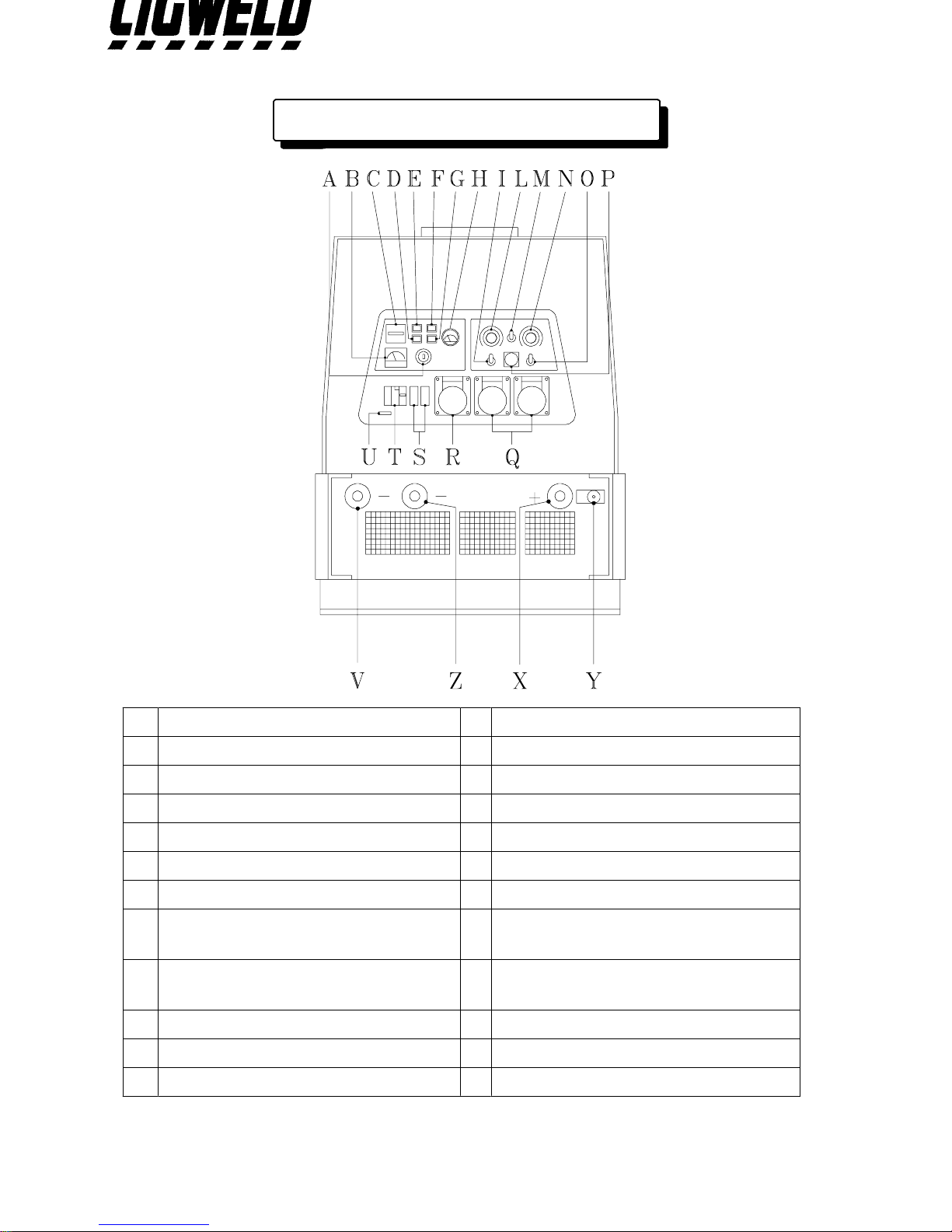
FRONT PANEL DESCRIPTIONS
Ignition key
A
Single phase voltmeter
B
Hourmeter
C
Water temperature lamp
D
Battery charge lamp
E
Oil pressure lamp
F
Overspeed lamp
G
Fuel meter
H
CC/CV mode select
I
Welding current control
L
Remote control switch
M
Arc force regulator
N
Basic-Cellulose switch
O
Wire feeder connector 14 pin
P
230V single phase outlet
Q
400V three phase outlet
R
16A single phase circuit breaker
S
ELCB (25A earth fault protection)
T
Serial number
U
Welding socket : negative connection
V
for CV-WORK
Welding socket : negative connection
Z
for CC-WORK
Welding socket : positive connection
X
Earth clamp connection
Y
7
Page 9
OPERATING INSTRUCTIONS
1.1 EQUIPMENT GROUNDING CONNECTION
^
This machine has auxiliary power capability and grounding of the frame and case is
recommended. Refer to your local Supply Authority or Australian Standard AS3000 for
detailed earthing instructions. Connect the eart h wire to the Eart h connection located
on the front of the machine.
2.1 EARTH FAULT PROTECTION
^
Supply Authorities recommend that protection devices immediately disconn ect all power
in the event of an earthing fault. This equipment is fitted with a Eart h Leakage Circuit
Br e a ker ( ELC B ) t h a t inte rr u p ts the a u x ilia ry pow e r c ir c u it w ith in 0 .2 s e c onds w h e n the
earth leakage is greater than 30 mA.
^
If a fa ult o c c ur s in eq u ipme nt c o nn ec t e d t o t he a ux iliar y pow er s upply, the outer casing
may become live and result in serious injury. The Engine Driven Welder must be
properly earthed. Refer to your local Supply Authority or Australian Standard AS3000
for detailed earthing instructions. The user is responsible for connecting this Engine
Driven Welder to earth.
3.1 USE AND TESTING OF EARTH FAULT PROTECTION
Switch the ELCB lever up to setting
^
I (ON)
. Test by pressing the test button while the
eng ine is ru nning . T his w ill re sult in t he ELC B t rip ping re sult ing th e lev er r et ur ning to
setting
^
If t he ELCB trip s rep eat edly while o perat ing au xiliary equ ipment , have t he eq uipment
0 (OFF)
. Reset to setting
I (ON)
.
tested by a qualified electrical tradesperson .
8
Page 10
4.1 STARTING ENGINE
^
Che c k t h a t en g ine s fuel tan k h a s be e n fille d with d ie s e l a nd th e su mp h a s be e n fille d w ith
lubricating oil as specified in the Engine Manual.
^
Pos itio n the ig n ition k e y on the first s te p for p re limina ry he a tin g the n s tart th e e n g ine by
moving key completely clockwise.
^
Aft er st art ing t he en gine , a llow it t o wa rm u p by w ait ing 5 minu te s befo r e lo ad ing t he
Engine Driven Welder.
^
Do not move the throttle control lever.
5.1 USE OF ENGINE DRIVEN WELDER AS A WELDER
^
Insert welding cable plugs into relevant sockets.
^
Set the current/voltage control knob on the front panel to the desired value on the
Engine Driven Welder. Take care that the REMOTE CONTROL switch is in 0 (OFF)
position.
^
Set the Arc Force control.
^
Remote current control can be achieved by using a remote control device.
^
When operating with remote control switch the remote switch control to position I
(ON) and connect the cable of the remote control unit to the 14 pin remote control
socket.
^
Connected the Electrode Lead to the positive terminal and the work lead to the
negative terminal.
Note: Stick electrodes are generally connected to the positive terminal but if in doubt
consult the electrode manufactures literature.
9
Page 11
6.1 CONSTANT CURRENT (CC) MODE
^
Set the CC/CV mode switch to the mode CC position.
^
If using a remote contro l pendant, plug remote pendant into the 14 pin remote co ntrol
socket and set the REMOTE CONTROL switch to the REMOTE position. Set the
REMOTE CONTROL switch to the PANEL position if a remote pendant is not used.
Note: When a remote control pendant is fitted (see 'P' on page 7), the Welding
current/voltage control is switched out of the circuit and remote control pendant
has full control over the welding current.
^
For MMAW (stick) welding connected the Electrode Lead to the positive terminal (see
'X' on page 7) and the work lead to the negative terminal (see 'Z' on page 7).
Note: Stick electrodes are generally connected to the positive terminal but if in doubt
consult the electrode manufactures literature.
^
For GTAW (TIG) welding connected the Electrode Lead to the negative terminal (see
'Z' on page 7) and the work lead to the positive terminal (see 'X' on page 7).
7.1 CONSTANT VOLTAGE (CV) MODE
^
Set the CC/CV mode switch to the mode CV position.
^
Connect wire feeder cable to 14 pin remote control socket.
^
If a remote co ntrol pendant is plugged into the remote contr ol socket of the wirefeeder
then set the REMOTE CONTROL switch to the REMOTE position. Set the REMOTE
CONTROL switch to the PANEL position if a remote pendant is not used.
Note: When a remote control pendant is fitted (see 'P' on page 7), the Welding
current/voltage control is switched out of the circuit and remote control pendant
has full control over the welding voltage.
^
For GMAW (MIG) welding connected the Electrode Lead to the positive terminal (see
'Y' on page 7) and the work lead to the negative terminal (see 'V' on page 7).
10
Page 12
8.1 USE OF ENGINE DRIVEN WELDER AS A
GENERATING SET
^
Start the engine ass described in section 4.1
^
Switch the ELCB lever up to setting I (ON). Switch the single phase 16A CB lever up
to setting I (ON).
^
The single phase voltmeter (see 'I' on page 7) reads approximately 170V when the
engine is at idle speed.
9.1 STOPPING ENGINE
^
Dis co nnec t a ny loa d fr om t he aux iliar y out let s a nd t he weld ing t er minals of t he E ng ine
Driven Welder.
^
Wait approximately 1 minute then turn the ignition key to the 0 position and the motor
will stop.
10.1 ENGINE PROTECTION
^
The DAS Engine Protection Device checks for low oil pressure, no battery charge, over
speed, high water temperature and low fuel level conditions when the Engine Driven
Welder is in operation.
^
When a low oil pressure, no battery charge, over speed, high water temperature or low
fuel level c o nd itio n o c cu rs t he D AS st o ps t he e ngin e a nd illu mina t es th e c or r es po nd ing
lamp o n t he c o nt r o l ( e xp ec t fo r t he lo w fue l lev el c o nd it io n ) . Whe n t he fau lt y c o nd it io n
has been removed the engine can be re-started.
^
Note that if the low oil pressure, no battery charge, over speed, high water temperature
or low fuel level c ond itio n is st ill pr ese nt w hen a fte r t he en gine is re- st art ed the n th e
DAS E ng ine P ro t ec t io n De vic e will s t op th e e ng ine af te r ap pr o ximat e ly one minu t e ha s
elapsed.
11.1 WARNING
^
In order t o preserve the engine performance CIGWELD strongly recommends that the
maintenance schedule is adhered to as specified in the engine manufacturer "Use and
maintenance" user manual. Poor maintenance could result in a shorter operating life,
decreased performance and loss of engine warranty.
^
DO NOT disconnect the battery from the Engine Driven Welder when the engine is
running as this action will cause the alternator regulator to fail.
11
Page 13
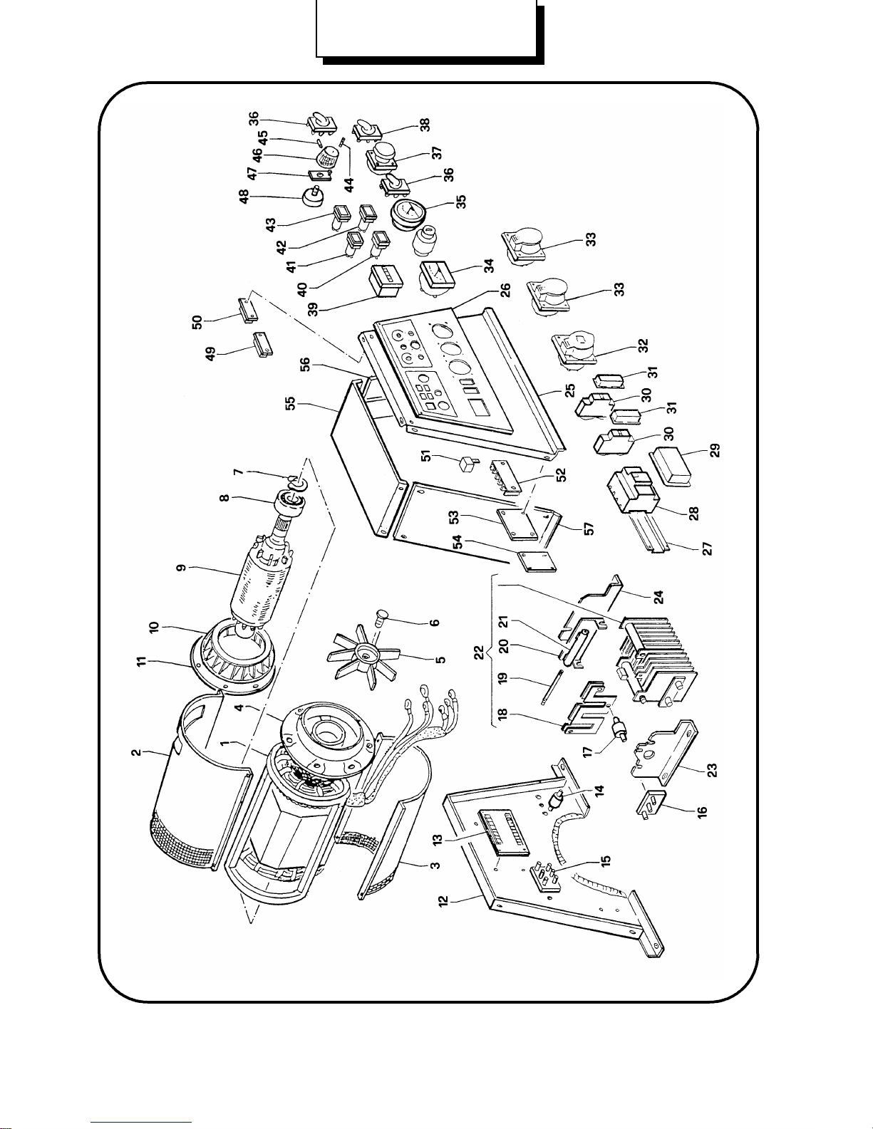
MPM 20/600 I-PS
(Part Number 636806)
12
Page 14
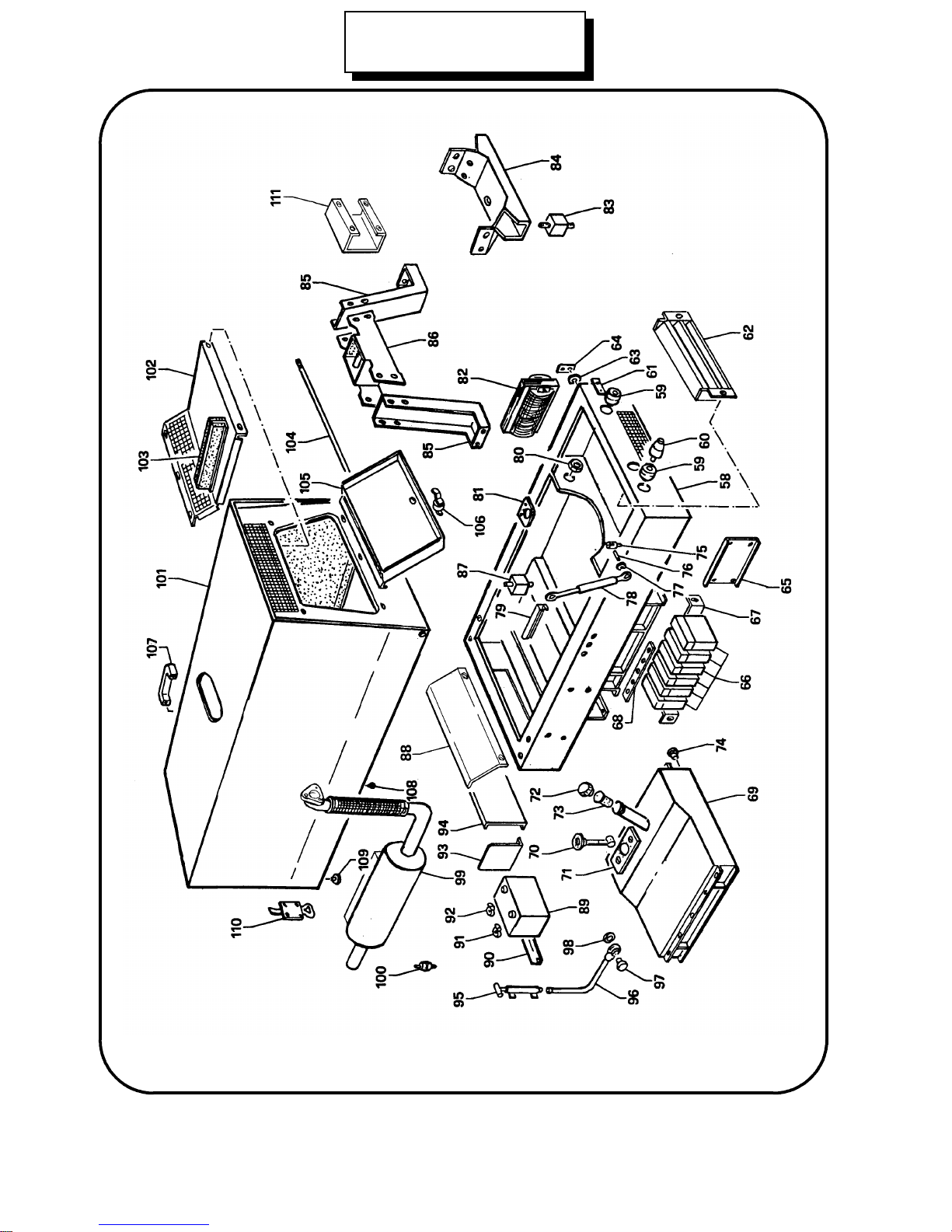
MPM 20/600 I-PS
(Part Number 636806)
13
Page 15
Spare parts list MPM 20/600 I-PS (Part Number 636806)
Item
no.
no.
DescriptionOrdering
StatorOGS194841
Stator protectionOGS193132
Stator protectionOGS193143
Flange with bearing seatOGS105104
FanOGS105255
ScrewOGS105246
Seeger ringOGSO9057
Bearing 100/45/25 2RSOGS9038
Shaft with rotorOGS193109
FanOGS1930910
Flex plateOGS1509211
PanelOGS1872612
Electronic panel GS9603/AOGS1857613
InsulatorOGS1170714
6 poles terminal boardOGS1036415
3 poles terminal boardOGS61416
20x20 shock absorberOGS1724517
ShuntOGS1872318
Tie rodOGS84619
Resistor supportOGS1872420
100Ohm-75W resistor OGS1277621
Rectifier assemblyOGS1872022
Left plate rectifierOGS1872123
Right plate rectifierOGS1872224
Front and coverOGS1870825
Front plateOGS1948726
Circuit breaker plateOGS1005727
25A earth fault protectionOGS83928
ProtectionOGS1393329
16A circuit breakerOGS63230
ProtectionOGS1319131
14
Page 16
Spare parts list MPM 20/600 I-PS (Part Number 636806)
Item
no.
no.
DescriptionOrdering
400V 20A three phase socket OGS1948332
230V 15A single phase socketOGS1948233
F.S. 300V voltmeterOGS32234
Fuel meterOGS1168835
Switch assemblyOGS1216336
Socket for remote control and wire feeder 14 polesOGS1822537
Basic/Cellulosic switch assemblyOGS91038
HourmeterOGS91239
Water temperature lampOGS1695940
Battery charge lampOGS1026441
Overspeed lampOGS1026342
Oil pressure lampOGS1945843
PinOGS1751944
Grub screwOGS1752145
Potentiometer knobOGS1884446
PlateOGS1872847
1K potentiometerOGS90948
115Vac relayOGS1437049
24Vac relayOGS1419750
12V relayOGSO33651
Terminal boardOGS1275852
DAS : automatic stop for engine protection OGS1561253
OGS1743554
DAS : automatic stop for engine protection
(over speed GS9407)
CoverOGS1660055
Right and coverOGS1660156
Left and coverOGS1660257
FrameOGS1913558
Welding outletOGS92359
Plug for welding outletOGS1477760
Earth clamp plateOGS1751461
Grate protectionOGS1913462
15
Page 17
Item
no.
no.
Spare parts list MPM 20/600 I-PS (Part Number 636806)
DescriptionOrdering
WasherOGS1698863
PlateOGS1698964
CoverOGS1919265
3x80µF capacitorOGS1734766
Plate for capacitorsOGS1948667
Plate for capacitorsOGS1576268
Fuel tankOGS1873269
Fuel floatOGS1571570
CoverOGS1832971
Fuel filter cap 2" gasOGS1662172
Fuel prefilter 2" gasOGS1662073
Fuel drain capOGSO92374
PinOGS1141075
TierodOGS1253176
WasherOGS1253277
Gas spring filterOGSO90778
Plate for gas spring filterOGS1913879
Rubber wire holderOGS1017480
Plate for fuel tankOGS1886581
ReactorOGS1528682
Shock absorberOGS1831483
Stator bracketOGS1931684
PlateOGS1895485
HookOGS1895586
Shock absorberOGS1827587
Radiator plateOGS1917388
92Ah 12V batteryOGS1057389
Battery clampOGS1008290
Positive battery charging clipOGS1424791
Negative battery charging clipOGS1424892
Battery plateOGS1917093
16
Page 18
Spare parts list MPM 20/600 I-PS (Part Number 636806)
Item
no.
no.
DescriptionOrdering
Battery coverOGS1913694
Oil drain pumpOGSO87095
Oil drain pipeOGS1811196
Oil pipe capOGS1722297
PackingOGS1873898
SilencerOGS1913799
Fuel prefilterOGS16468100
CanopyOGS18960101
Internal cover deflectorOGS18740102
Internal short deflectorOGS18741103
Pivot shaftOGS16005104
OGS18743105
OGS13859106
Instrument front cover
(*)
Pin
(*)
HandleOGS14916107
Rubber pufferOGS14300108
Shock absorberOGS12230109
Frame locking hookOGS10530110
Air filter supportOGS18965111
(*) Only on request
17
 Loading...