

Page 1
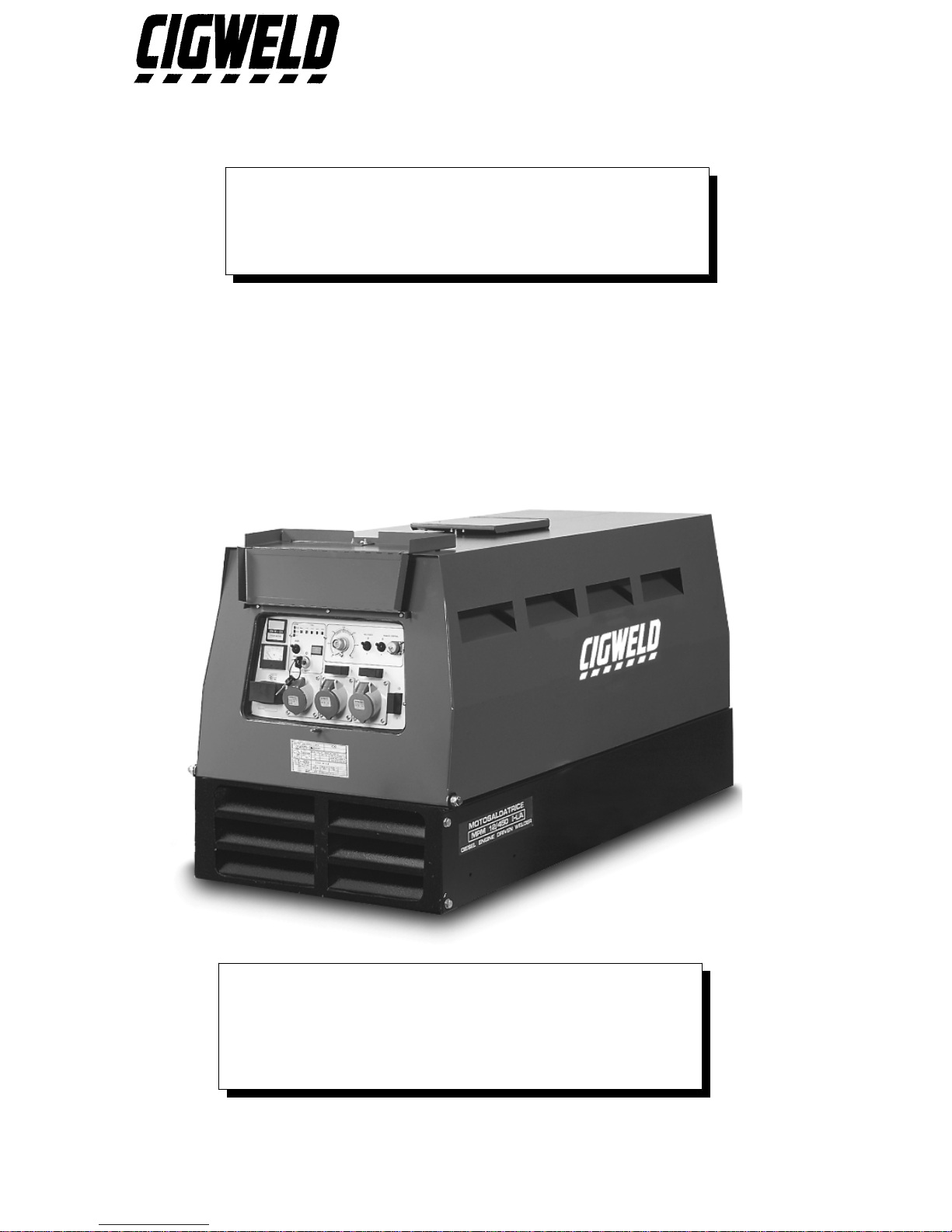
ENGINE DRIVEN WELDER
GENERATING SET
MPM 12/400 I-KA
(Part Number 636804)
DOC No: EDW0005 Date: 16-July-97
Issue No: 2
Page 2
GENERAL USE INSTRUCTIONS
Read the in structions carefully; proceed according to the regulations in use in t he
country where the machine will operate.
TRANSPORTATION
Y
The machine must be fixed securely to t he motor vehicle if it has to be moved to t he
place of use. Raise the machine using the lifting eye if the model provides it;
o the rwise , lift it u sing a fo rk lift, ta king ca re t hat t he we ight is w ell bala nced on t he
two forks. Keep well clear during these operat ions; furthermore, we suggest not t o
keep the machine suspended for long.
Y
If the machine is mounted on a wheels trolley or trailer, be sure the machine is stable
and secure before use.
CAUTION
Y
Note: The generating set or the welder is furnished WITHOUT lubricating oil.
Provide the machine with "10 W 40" multi-grade oil indicated for temperatures
from - 20°C to 40° C in the quantity indicated in the engine SPECIFICATION
section.
Y
Note: If the mach ine is fitte d with a water c ooled engine fill the radiat or circuit with a
solution made up by 50% water and 50% antifreeze liquid in the quantity indicated in
the engine SPECIFICATION section.
Y
Note: T he gen e r a tin g s e t is fur nis h e d w ith a fla t ba tte r y a n d w ithou t a c id . Fill it u s in g
sulphuric acid in a 30% - 40% concentrated solution to cover t he elements. During
this operation, we suggest the operat or use prot ective gloves and goggles; accidental
skin contact with the sulphuric acid solut ion must be washed up immediat ely with
cold water and, if necessary, a doctor must be consulted.
Y
Note: Do not disconnect battery cables when the engine runs. This could result in
serious damage to the machine.
Y
Note: BEFORE OPERATING THE MACHINE the neutral, or the equivalent
winding point, MUST be connected effectively to earth using an earth stake (without
any switch or other device that may interrupt the electrical connection) from the earth
stud available on the machine, and identified by the symbol:
Y
Y
Note: for normal transportation, follow the instructions as specified in the
TRANSPORTATION section.
1
Page 3
RUNNING IN
For the first 50 hours of operation of the machine do not employ more than 70% of the
maximum power indicated in the technical specifications.
STARTING AND WORKING
1- Make the earth connection (see the USE INSTRUCTIONS).
2- If the machine model IS NOT equipped with a earth leakage circuit breaker the
available socket is intended ONLY for connecting the machine to a switchboard
equipped with all protection devices imposed by current law regulations.
3- Check the state and efficiency of the cables.
4- Make sure that all the switches and electric connections are in the right position for
starting (see USE INSTRUCTIONS and CONTROL PANEL DESCRIPTIONS).
5- Use the machine in well ventilated places, taking care that the exhaust gas and the
welding fumes produced (where welders are used) do not st agnate. Keep the machine
away from walls or other obstacles in order to avoid air or gas recycling. If the
machine is employed in closed places, use forced ventilation in order to ensure pro per
air recycling.
6- While welding, eyes and body must be protected by gloves, mask and appropriate
clothes.
7- Fu e l r e fill mu s t not be made while s mok in g or c los e to flame s . This op e ration mu s t
be done when the engine is switched off.
8- Do not over fill the tank and clean up any spillage.
9- Check daily for loss of fuel or lubricating oil.
10-For machines provided with a liftable canopy engage the canopy securing brackets
where fitted.
WARNING
Y
Do not connect the machine to the commercial electric network.
Y
Do not work close to flammable materials or where there is explosive gas or vapours.
Y
Do not work in confined or poorly ventilated places.
Y
Do not touch the exhaust muffler or adjacent components.
Y
Do not carry out service operations while the engine is running.
Y
Any service on the electrical circuit must be done when the engine is stopped and only
by qualified technicians.
Y
Keep clear of moving parts of the engine while it is operat ing and do not approach the
machine with loose fitting clothing.
SERVICE AND CLEANING
We suggest frequent cleaning of the machine since the presence of dirt can co mpromise
efficiency.
The frequency of this operation depends on the environment in which the machine is
used. We advise to pay special care to the service of::
OIL LEVEL, OIL FILTER, AIR FILTER, FUEL FILTER, COOLING LIQUID
LEVEL, RADIATOR, VENTILATION DUCTS AND INTAKES, BATTERY
ENGINE USE AND SERVICE manual and the SPECIFICATION section to know
how and when it is useful to do it. The extraordinary service operations not mentioned
herein require the aid of specialised technicians (see the Engine Dealers list).
2
Page 4

For service intervals consult the ENGINE USE AND SERVICE manual and the
SPECIFICATION.
ADJUSTMENTS AND REGULATIONS
All necessary contr ols are located on the main control panel and are properly explained
in the section FRONT PANEL DESCRIPTION.
We advise the operator against tampering with the engine or the internal electrical
components.
Note: Modification of the normal parameters can compromise the reliability of the
machine.
PROLONGED STANDING PERIODS
If the machine has to be stopped for a long period (more t han one year), we suggest to
leave the motor oil and the fuel in and the water in the radiator in order to avoid
oxidising effects.
When the machine is to be used, the liquids must be replaced, the battery must be
charged; the belts, pipes and rubber hoses must be checked and a visual inspection of the
electrical connections must be done.
SCRAPPING
In order to pr eserve the environment, it is advised to dispose of the oil, fuel and battery
in an approved manner. For the complete range of materials, see the list below:
FERROUS and NON-FERROUS MATERIALS:
steel, cast iron, aluminium, copper, brass are used in the struct ure of engine,
alternator, transformers, etc.
PLASTIC MATERIALS:
rubber, bakalite, epovit, lexan are used for the instruments, engine pipes,
junction boxes and connectors, fuel tank, fuel cap, wheels, anti-vibration
dampers, condenser housings, fans, belts, filters and hoses.
ELECTRONIC MATERIALS:
various components, diodes, resistors, electronic panels.
VARIOUS MATERIALS:
rock wool, sound proofing materials.
LIQUIDS:
fuel, gasoline, cooling liquids, battery acid.
3
Page 5
TECHNICAL SPECIFICATION
POWER PLANT INFORMATION
636804 Part number
MPM 12/400 I-KADescription
WELDING GENERATOR D.C.
400A @ 36VMaximum power
350A @ 34VRated output at 60% duty cycle
30A to 400ARange of continuous control
5 minutesDuty cycle period
70VDC open circuit voltage
FInsulation class
IP 23Mechanical protection
30A to 400A CC mode
18V to 40VCV mode
AUXILIARY GENERATOR
Asynchronous Generator type
12kVA @ 400VThree phase power
10kVA @ 230VSingle phase power
50 HzFrequency
RECOMMENDED MANUAL METAL ARC WELDING ELECTRODE
Maximum Electrode DiameterElectrode Description
6.0mmGeneral purpose & low hydrogen
6.0mmCellulose
6.0mmIron powder
4
Page 6
ENGINE
Kubota D 1105-E Make/Type
3Number of cylinders
1124 cc.Displacement
25 HPDiesel engine output
3000 rpmEngine speed
WaterCooling
36.5 Litres Fuel tank capacity
5.1 LitresOil capacity
ElectricStarter
12V - 43 AhBattery
97 dB(A)Acoustic energy emission
89 dBAcoustic pressure @ 1 metre
77 dBAcoustic pressure @ 4 metre
275 gram/kW/hourAverage fuel consumption
15 hours Average operating hours
DIMENSIONS AND WEIGHT
1590mm x 730mm x 920 mmDimensions (Length x Width x Height)
460 KgWeight
5
Page 7
ENGINE WARRANTY
AND SPARE PARTS
1.1 INTRODUCTION
Car efully follow the KUBOTA engine opera tion manua l for s afe opera tion and long service life of
this product.
1.2 ENGINE WARRANTY
To secu r e war r a nt y for the engine ensur e tha t the war r a nt y cer t ific a te is fill in and mailed t o the Tutts
state branch office (KUBOTAs Australian engine distributor)
The engine is warranted for twelve (12) months from date of purchase or one thousand (1000) hours
which ever is sooner . T his wa r r a nt y is limit ed to t he rep la cement or r ep a ir , a t T ut t s wor ks hop of a ny
parts proven defective, under normal use and service within the warranty period. For warranty
service outside a Tutts workshop, all travelling time and mileage incurred, will of necessity, be
charged to the owner of the equipment who ordered the off site warranty repair(s).
New engine warr anty does not a pply to maintenance items such as filt ers, hoses, belts, pr eheaters,
injection nozzles, packing and seals, etc.
Tutts Branch Network Tutts (Sydney): 2 South St. Rydalmere NS W 2116
Tutts (Perth): 50 Great Eastern Hwy South Guildford WA 6055
Tutts (Brisbane): 39 Suscatand St Rocklea QLD 4106
Tutts (Melbourne): Gwelo St Tottenham VIC 3012
.
Tutts Dealer Network
Queensland: Andrew's Agricultural Centre Pty Ltd - Goranvale, Cairns Ph: (070) 565222
- Innisfail Ph: (070 616466
- Tully Ph: (070) 681311
Fishabout Pty Ltd - Mackay Ph: (079) 534752
Dore Power Equipment Pty Ltd - Roma Ph: (076) 221883
New South Wales: SJ & ML Foster - Moree Ph: (067) 525 488
Clares Diesel Service Pty Ltd - Coffs Harbour Ph: (066) 525121
Kentan Pty Ltd - Hexham, Newcastle Ph: (049) 648275
Tasmania: Diesel & Marine Pty Ltd - Newtown, Hobart Ph: (03) 62281755
South Australia: Mac Pac Sales & Service Pty Ltd - Wingfield, Adelaide Ph: (08) 82431422
1.3 SPARE PARTS
KUBOTA engine:Contact Tutts (in Australia) for spare parts and service assistance. Specify the
engine model number, serial number, name of part (with code number), Engine
Driven Welder model name (with code number) and manufacturers name when you
contact your KUBOTA Dealer. KUBOTA guarantees an efficient technical support
throughout Australia and New Zealand.
Generator and equipment: Contact your local CIGWELD Distributor for spare parts. Specify the
Engine Driven Welders model number, serial number and name of part
(with code number) when ordering spare parts. Refer to the Spare Parts
List from page 13.
6
Page 8
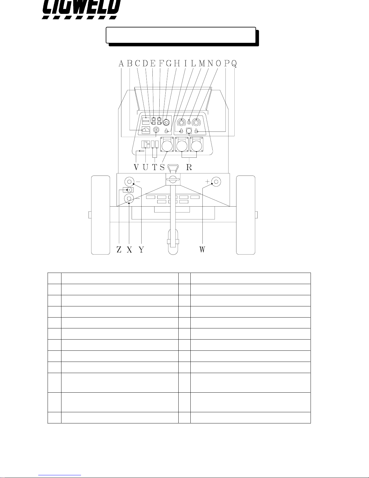
FRONT PANEL DESCRIPTIONS
Ignition key
A
Single phase voltmeter
B
Hourmeter
C
Water temperature lamp
D
Battery charge lamp
E
Oil pressure lamp
F
Glow plug lamp
G
Fuel meter
H
Throttle switch
I
CC/CV mode select
L
Welding current control
M
Remote control switch
N
Arc force regulator
O
Basic / Cellulose switch
P
Wire feeder connector 14 pin
Q
230V single phase outlet
R
400V three phase outlet
S
16A single phase circuit breaker
T
ELCB (25A earth fault protection)
U
Serial number
V
Earth connection
Z
Welding socket : negative connection
X
for CV-WORK
Welding socket : negative connection
Y
for CC-WORK
Welding socket : positive connection
W
7
Page 9
OPERATING INSTRUCTIONS
1.1 EQUIPMENT
GROUNDING CONNECTION
^
This machine has auxiliary power capability and grounding of the frame and case is
recommended. Refer to your local Supply Authority or Australian Standard AS3000 for
detailed earthing instructions. Connect the eart h wire to the Eart h connection located
on the front of the machine.
2.1 EARTH FAULT PROTECTION
^
Supply Authorities recommend that protection devices immediately disconn ect all power
in the event of an earthing fault. This equipment is fitted with a Eart h Leakage Circuit
Br e a ker ( ELC B ) t h a t inte rr u p ts the a u x ilia ry pow e r c ir c u it w ith in 0 .2 s e c onds w h e n the
earth leakage is greater than 30 mA.
^
If a fa ult o c c ur s in eq u ipme nt c o nn ec t e d t o t he a ux iliar y pow er s upply, the outer casing
may become live and result in serious injury. The Engine Driven Welder must be
properly earthed. Refer to your local Supply Authority or Australian Standard AS3000
for detailed earthing instructions. The user is responsible for connecting this Engine
Driven Welder to earth.
3.1 USE AND TESTING OF EARTH FAULT PROTECTION
Switch the ELCB lever up to setting
^
I (ON)
. Test by pressing the test button while the
eng ine is ru nning . T his w ill re sult in t he ELC B t rip ping re sult ing th e lev er r et ur ning to
setting
^
If t he ELCB trip s rep eat edly while o perat ing au xiliary equ ipment , have t he eq uipment
0 (OFF)
. Reset to setting
I (ON)
.
tested by a qualified electrical tradesperson.
8
Page 10
4.1 STARTING ENGINE
^
Che c k t h a t en g ine s fuel tan k h a s be e n fille d with d ie s e l a nd th e su mp h a s be e n fille d w ith
lubricating oil as specified in the Engine Manual.
^
Po s itio n t h e ig nit io n ke y o n t he firs t st e p fo r pr elimina r y hea t ing o f t he g low plu gs , th e
glo w plu g lig ht illumin at es . When glo w plu g light t u rns o ff, st ar t th e e ngin e b y mov ing
key completely clockwise.
^
Aft er st a rt ing th e e ngin e, allo w it t o wa rm u p b y wait ing 10 s min ut e b efo r e lo ad ing t he
Engine Driven Welder.
^
Do not move the throttle control lever.
5.1 USE OF ENGINE DRIVEN WELDER AS A WELDER
^
Insert welding cable plugs into relevant sockets.
^
Set the current/voltage control knob on the front panel to the desired value on the
Engine Driven Welder. Take care that the REMOTE CONTROL switch is in 0 (OFF)
position.
^
Set the Arc Force control to I (ON) or 0 (OFF) position.
^
Remote current control can be achieved by using a remote control device.
^
When operating with remote control switch the remote switch control to position I
(ON) and connect the cable of the remote control unit to the 14 pin remote control
socket.
^
Connected the Electrode Lead to the positive terminal and the work lead to the
negative terminal.
Note: Stick electrodes are generally connected to the positive terminal but if in doubt
consult the electrode manufactures literature.
^
In standby mode, ie not welding or supplying power to auxiliary o ut le ts , t h e en g in e id le s
at approximately 2000 rpm.
^
When an arc is struck or t he unit is supplying power to auxilia r y outle ts the n the e ng in e s
speed increases to appr oximately 3000 rpm. The returns to idle speed approximately 25
seconds after welding has ceased.
9
Page 11
6.1 CONSTANT CURRENT (CC) MODE
^
Set the CC/CV mode switch to the mode CC position.
^
If using a remote contro l pendant, plug remote pendant into the 14 pin remote co ntrol
socket and set the REMOTE CONTROL switch to the REMOTE position. Set the
REMOTE CONTROL switch to the PANEL position if a remote pendant is not used.
Note: When a remote control pendant is fitted (see 'Q' on page 7), the Welding
current/voltage control is switched out of the circuit and remote control pendant
has full control over the welding current.
^
For MMAW (stick) welding connected the Electrode Lead to the positive terminal (see
'W' on page 7) and the work lead to the negative terminal (see 'Y' on page 7).
Note: Stick electrodes are generally connected to the positive terminal but if in doubt
consult the electrode manufactures literature.
^
For GTAW (TIG) welding connected the Electrode Lead to the negative terminal (see
'Y' on page 7) and the work lead to the positive terminal (see 'W' on page 7).
7.1 CONSTANT VOLTAGE (CV) MODE
^
Set the CC/CV mode switch to the mode CV position.
^
Connect wire feeder cable to 14 pin remote control socket.
^
If a remote co ntrol pendant is plugged into the remote contr ol socket of the wirefeeder
then set the REMOTE CONTROL switch to the REMOTE position. Set the REMOTE
CONTROL switch to the PANEL position if a remote pendant is not used.
Note: When a remote control pendant is fitted (see 'Q' on page 7), the Welding
current/voltage control is switched out of the circuit and remote control pendant
has full control over the welding voltage.
^
For GMAW (MIG) welding connected the Electrode Lead to the positive terminal (see
'W' on page 7) and the work lead to the negative terminal (see 'X' on page 7).
10
Page 12
8.1 USE OF ENGINE DRIVEN WELDER AS A GENERATING SET
^
Start the engine ass described in section 4.1
^
Switch the ELCB lever up to setting I (ON). Switch the single phase 16A CB lever up
to setting I (ON).
^
The single phase voltmeter (see 'I' on page 7) reads approximately 170V when the
engine is at idle speed.
^
In standby mode, ie not welding or supplying power to auxiliary o ut le ts , t h e en g in e id le s
at approximately 2000 rpm.
^
When an arc is struck or t he unit is supplying power to auxilia r y outle ts the n the e ng in e s
speed increases to appr oximately 3000 rpm. The returns to idle speed approximately 25
seconds after the auxiliary equipment is disconnected from the auxiliary outlets.
9.1 STOPPING ENGINE
^
Dis co nnec t a ny loa d fr om t he aux iliar y out let s a nd t he weld ing t er minals of t he E ng ine
Driven Welder.
^
Wait approximately 1 minute then turn the ignition key to the 0 position and the motor
will stop.
11
Page 13
10.1 ENGINE PROTECTION
^
The DAS Engine Pro tection Device checks for low oil pressure, no battery charge, high
water temperature and low fuel level co ndit ion s whe n th e Eng ine D riven Welde r is in
operation.
^
When a low oil pressure, no battery charge, high water temperature or low fuel level
co ndit ion occ urs the DAS sto ps the engin e and illuminat es t he c or res po nding lamp o n
the contro l (expect for the low fuel level condition). When the faulty condition has been
removed the engine can be re-started.
^
Note that if the low oil pressure, no battery charge, high water temperature or low fuel
level c o nd it ion is s t ill pr es ent w he n aft e r t he e ng ine is r e- st ar t ed t he n t he DA S E ng ine
Protection Device will stop the engine after approximately one minute has elapsed.
11.1 WARNING
^
In order t o preserve the engine performance CIGWELD strongly recommends that the
maintenance schedule is adhered to as specified in the engine manufacturer "Use and
maintenance" user manual. Poor maintenance could result in a shorter operating life,
decreased performance and loss of engine warranty.
^
DO NOT disconnect the battery from the Engine Driven Welder when the engine is
running as this action will cause the alternator regulator to fail.
12
Page 14
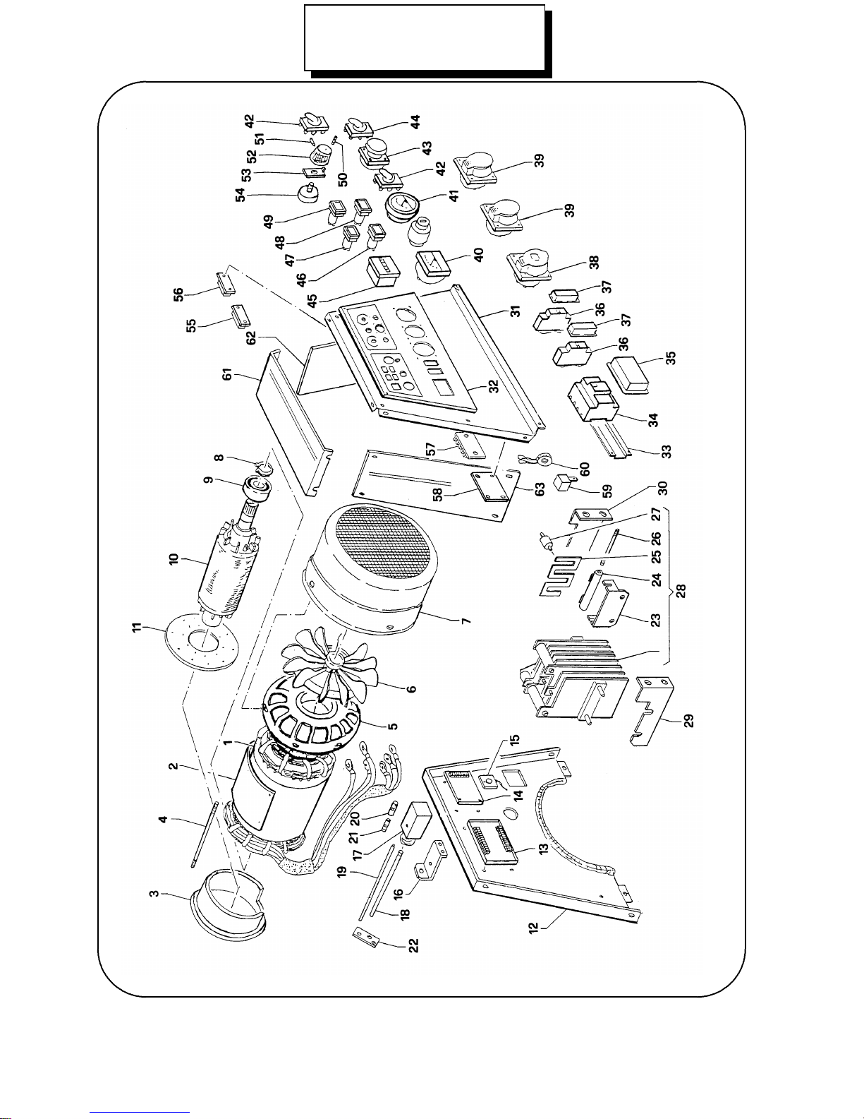
MPM 12/400 I-KA
(Part Number 636804)
13
Page 15
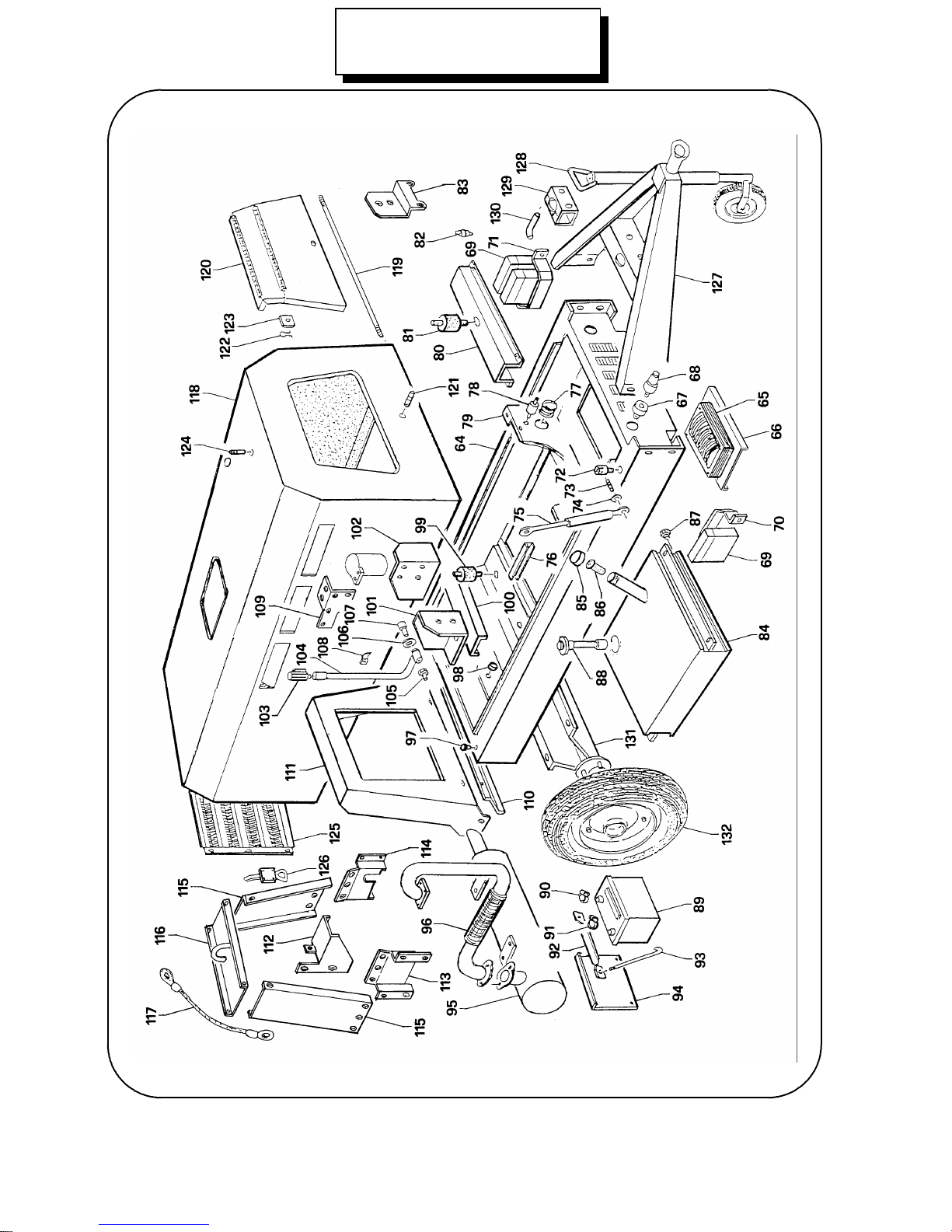
MPM 12/400 I-KA
(Part Number 636804)
14
Page 16
SPARE PARTS LIST MPM 12/400 I-KA (Part Number 636804)
Item
no
DescriptionOrdering
no
StatorOGS194931
Stator protectionOGS185122
Engine connection flangeOGS184863
Stator tie rodOGS114464
Flange with bearing seatOGS186995
FanOGS101756
Fan coverOGS187647
CirclipOGSO9058
Bearing 100/45/25 2RS OGS9039
Shaft with rotorOGS1836810
Flex plateOGS1433911
PanelOGS1836912
Electronic panel GS9603/AOGS1857613
Amperometric relay OGS99314
Diode / heatsink assyOGSOO7915
Solenoid supportOGS1625916
60x60x150 solenoidOGS99117
Shaft for solenoidOGS1267318
Wire for solenoidOGS1267419
Fuse holderOGS58820
8A fuseOGS1228421
Bowden supportOGS1831022
Resistor supportOGS1872423
100 Ohm - 75 W resistorOGS1277624
ShuntOGS1872325
Resistor tie rodOGS84626
20x20 shock absorberOGS1724527
Rectifier assemblyOGS1876028
Left plate rectifierOGS1887229
Right plate rectifierOGS1887330
Front and coverOGS1870831
15
Page 17
SPARE PARTS LIST MPM 12/400 I-KA (Part Number 636804)
Item
no
DenominationOrdering
no
Front plateOGS1949832
Plate for earth fault protectionOGS1005733
25A earth fault protectionOGS83934
ProtectionOGS1393335
16A circuit breakerOGS63236
ProtectionOGS1319137
400V 20A three phase socketOGS1948338
230V 15A single phase socketOGS1948239
300V F.S. voltmeterOGS32240
Fuel meterOGS1168841
Switch assemblyOGS1216342
Socket for remote control and wire feeder 14 poles OGS1822543
CC/CV switch assemblyOGS91044
HourmeterOGS91245
Water temperature lampOGS1695946
Battery charge lampOGS1026447
Glow plug lampOGS1538048
Oil pressure lampOGS1945849
PinOGS1751950
Grub screwOGS1752151
Potentiometer knob OGS1884452
PlateOGS1872853
1K potentiometerOGS90954
115V ac relayOGS1437055
24V ac relayOGS1419756
Terminal board assemblyOGS1276357
DAS: automatic stop for engine protection OGS1650558
12V relayOGSO33659
Amperometric transformerOGS1340760
CoverOGS1626761
Left hand coverOGS1626562
16
Page 18
SPARE PARTS LIST MPM 12/400 I-KA (Part Number 636804)
Item
no
DenominationOrdering
no
Right hand coverOGS1626663
FrameOGS1725564
ReactorOGS1278665
PlateOGS1886966
Welding outlet OGS83667
Plug for welding outletOGS88668
3x60µF capacitorOGS1694069
Plate for capacitorOGS1689670
Plate for capacitorsOGS1693471
PinOGS1141072
Tie rodOGS1253173
WasherOGS1253274
60kg gas spring filterOGS1162175
Plate for canopyOGS1552676
1" ¼ gas rubber wire holderOGS1026777
InsulatorOGS1170778
PanelOGS1837079
Stator bracketOGS1842780
50x50 shock absorberOGS92781
Fuel prefilterOGS1646882
Air filter supportOGS1949983
Fuel tankOGS1524684
Fuel filter capOGS1627185
Fuel prefilterOGS1627286
Fuel drain capOGSO92387
Fuel level gauge OGS1561388
43Ah 12V BatteryOGS42589
Positive battery charging clipOGS1424790
Negative battery charging clipOGS1424891
Battery clampOGS1172692
Tie rodOGS94893
17
Page 19
SPARE PARTS LIST MPM 12/400 I-KA (Part Number 636804)
Item
no
DenominationOrdering
no
Battery coverOGS1619094
SilencerOGS1619195
Silencer extension OGS1830896
Rubber pufferOGS1430097
Dia. 16 rubber wire holder OGS1131298
50x35 shock absorberOGS1349399
Engine supportOGS17749100
Left engine support bracketOGS18302101
Right engine support bracketOGS18303102
3/8" capOGS11817103
Oil drain pipeOGS14775104
ScrewOGS18309105
WasherOGSO873106
M14 screwOGSO872107
Clip for pipeOGS12728108
Filter supportOGS18618109
PlateOGS18871110
PanelOGS18870111
Engine stator protectionOGS18425112
Left plate for hookOGS19496113
Right plate for hookOGS19497114
Panel support hookOGS19495115
HookOGS19494116
Steel cableOGS16119117
CanopyOGS16278118
Pivot shaftOGSO881119
Instrument front coverOGS16279120
Locking hook (closed front cover)OGS12529121
SpringOGS12526122
PlateOGS12527123
Locking hook (opened front cover)OGS12528124
18
Page 20
SPARE PARTS LIST MPM 12/400 I-KA (Part Number 636804)
Item
no
DenominationOrdering
no
Air grateOGS16280125
Frame locking hookOGS10530126
Rubber OGSOO90127
Jog wheel OGS949128
Adjustable clampOGSO548129
Brace OGSO924130
Axle OGS15247131
Wheel OGS10538132
19
 Loading...