

Page 1
TS2
Service
Thermocot
Manual
iN
i
|
|
ή
[
il
Eu
ag
페
1
1
EL
Ц
|
CIG
Health
e
Commonweatih
Care
Indu
С.М.
т
000
029
|
729
pi
Page 2

TS2
Thermocot
Service
Manual
Page 3
TS2
Thermocot
Index
SPECIFICATION
Notes
to
specification
Warning
Caution
CHECKOUT
Photographs
Cleaning
Photographs
Alarm
TECHNICAL
Routine
Calibration
Air
Photographs
Statements
Table
Maintenance
Flow
Diagram
Statements
PROCEDURE
DESCRIPTION
Procedure
Service
Manual
13,
17,
25
Page
4
5
8
9
10
12
14
18
19
20
23
23
24
25
MECHANICAL
General
Front
Panel
Canopy
Frame
Motor
Assembly
ELECTRONICS
Circuit
Software
Control
Power
Display
Alarm
Circuit
SERVICE
Description
PCB
PCB
Diagram
CENTRES
DRAWINGS
Assembly
Assembly
Assembly
Assembly
Description
PCB
PCB
AND
PARTS
LISTS
47,
26,
28,
30,
32,
48,
27
29
31
33
34
35
42
44
45
46
46
49
50
Page 4
TS2
Thermocot
Service
Manual
Specifications
4.
1.
Introduction
Control
Temperature
Range
The
TS2
Thermocot
incubator
transported
operates
features
control
safety
See
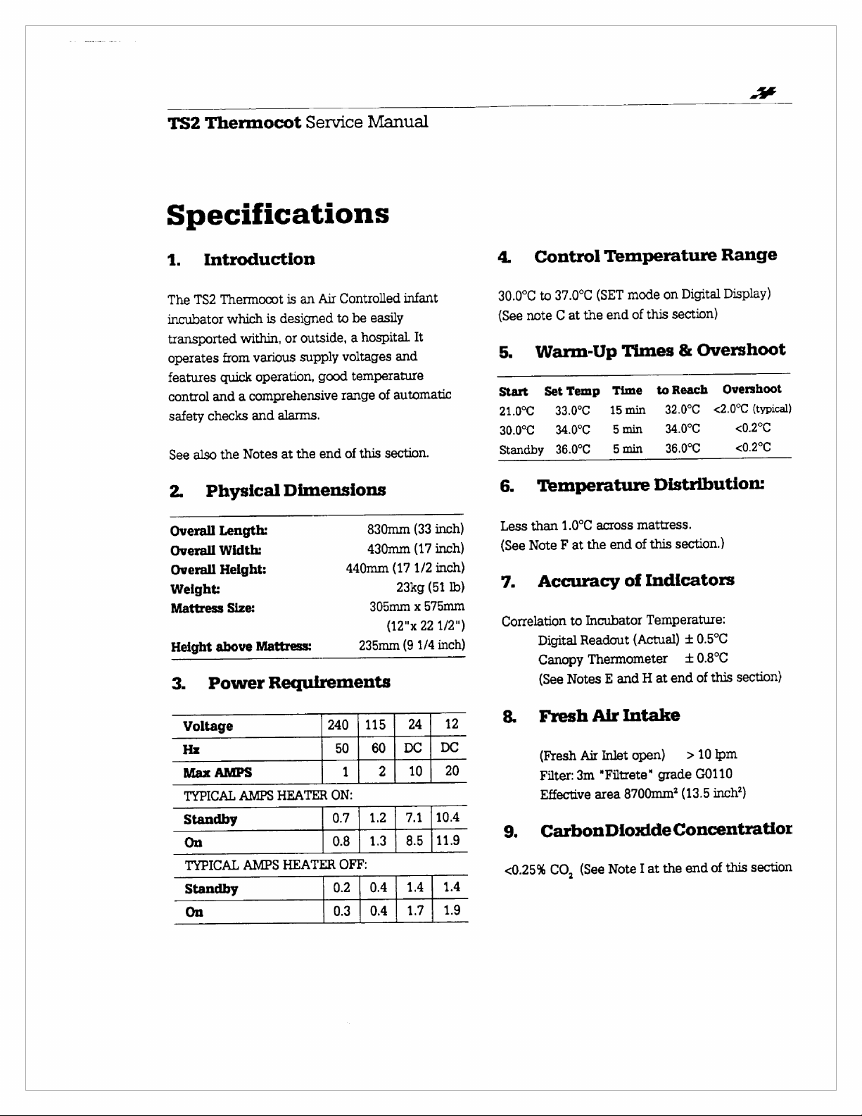
2.
Overall
Overall
Overall
Weight:
Mattress
Height
3.
from
quick
and a comprehensive
checks
also
the
Physical
Length:
Width:
Height:
above
Power
which
is
within,
various
operation,
and
Notes
Size:
Mattress:
Requirements
is
an
Air
Controlled
designed
or
alarms.
at
Dimensions
to
be
outside, a hospital
supply
voltages
good
temperature
range
the
end
of
this
440mm
235mm
easily
and
of
automatic
section.
830mm
430mm
(17
23kg
305mm
(12"x
infant
It
(33
inch)
(17
inch)
1/2
inch)
(51
575mm
x
22
(9
1/4
lb)
1/2")
inch)
37.0°C
to
30.0°C
(See
note
C
Warm-Up
5.
Start
21.0°C
30.0°C
Standby
6.
Less
(See
7.
Correlation
SetTemp
33.0°C
34.0°C
36.0°C
Temperature
than
Note F at
Accuracy
Digital
Canopy
(See
(SET
at
the
1.0°C
across
the
to
Incubator
Readout
Thermometer
Notes
on
mode
end
of
this
Times
Time
15min
5min
Smin
end
E
toReach
32.0°C
34.0°C
36.0°C
Distribution:
mattress.
of
this
of
Indicators
Temperature:
(Actual) + 0.5°C
end
at
H
and
Digital
section)
Overshoot
&
<2.0°C
section.)
340.80
this
of
Display)
Overshoot
(typical)
<0.2°C
<0.2°C
section)
Voltage
Hz
Max
AMPS
TYPICAL
Standby
On
TYPICAL
Standby
On
AMPS
AMPS
HEATER
240
50 | 60 | DC | DC
ON:
0.7 | 1.2 | 7.1
0.8 | 13 | 8.5
HEATER
0.2 | 04 | 14 | 14
0.3 | 0.4 | 1.7 | 19
|115 | 24|
1|
2|
OFF:
10|
12
20
|104
|119
8.
Fresh
(Fresh
Filter:
Effective
CarbonDioxideConcentratior
9.
<0.25%
CO,
Air
Air
Inlet
3m
"Filtrete“
area
Note
(See
Intake
open) > 10
grade
8700mm?
at
I
the
G0110
(13.5
end
pm
inch?)
this
of
section
Page 5
TS2
10.
1.
il.
11.
Across
12.
i,
i.
Ш.
iv.
v.
13.
(See
the
Thermocot
Oxygen
With
applied-
With
8
lpm
after
an
ambient
(See
notes
Air
Velocity
mattress
Sound
At
centre
Sameas
8
lpm
Oxygen
Same
as
10
Ipm
Same
as
Alarm
Alarm
level
in
front
(See
Note
Alarms
Alarm
Fresh
5
sounding
Concentration
Fresh
Air
Inlet
maximum
Air
Inlet
Oxygen
minutes
of
B,
J)
-
<0.1
applied,
from
21%
m/s
Levels
of
Mattress
(i)
but
with
applied
(i)
but
with
Oxygen
of
Chart,
applied
(i)
but
with
3
metres
incubator
K)
and
serviceMana
open,
5
Ipm
Oxygen
40%
O,
Closed,
O,
-
55%
O,
minimum
(typical)
52
dbA
(max)
50
dbA
(typical)
Note
52dbA
54dbA
60dbA
>65dbA
L)
(typical)
(typical)
(typical)
NOTES:
A.
This
cannot
incubator
automatic
temperature.
adjusted
requirements
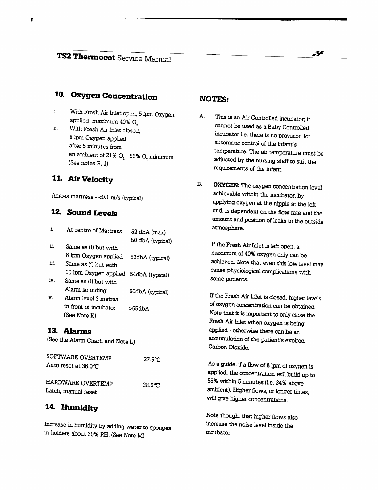
B.
OXYGEN:
achievable
applying
end,
amount
atmosphere.
If
the
maximum
achieved.
cause
some
If
the
of
oxygen
Note
that
Fresh
applied
accumulation
Carbon
is
an
Air
Controlled
be
used
as
ie.
there
control
by
The
within
oxygen
is
dependent
and
Fresh
of
Note
physiological
patients.
Fresh
Air
of
The
air
the
nursing
of
the
oxygen
the
at
on
position
Air
Inlet
40%
oxygen
that
Inlet
concentration
it
is
important
Air
Inlet
when
-
otherwise
Dioxide.
of
the
there
patient's
incubator;
a
Baby
Controlled
is
no
provision
the
infant's
temperature
staff
to
suit
infant.
concentration
incubator,
the
nipple
the
flow
of
leaks
is
left
only
even
this
complications
is
closed,
can
to
oxygen
can
by
at
the
rate
to
the
open,
a
can
be
low
level
with
higher
be
obtained.
only
close
is
being
be
an
expired
ae
一
it
for
must
be
the
level
left
and
the
outside
may
levels
the
一
SOFTWARE
Auto
reset
HARDWARE
Latch,
manual
14.
Humidity
Increase
in
holders
OVERTEMP
at
in
humidity
about
36.0°C
OVERTEMP
reset
by
20%
RH.
adding
(See
water
Note
37.5°C
38.0°С
to
sponges
M)
As
a
guide,
applied,
55%
within
ambient).
will
give
Note
though,
increase
incubator.
the
if
a
flow
the
concentration
5
minutes
Higher
higher
flows,
concentrations.
that
higher
noise
level
of
8
(i.e.
inside
lpm
or
of
oxygen
will
build
34%
above
longer
times,
flows
also
the
up
is
to
Page 6
TS2
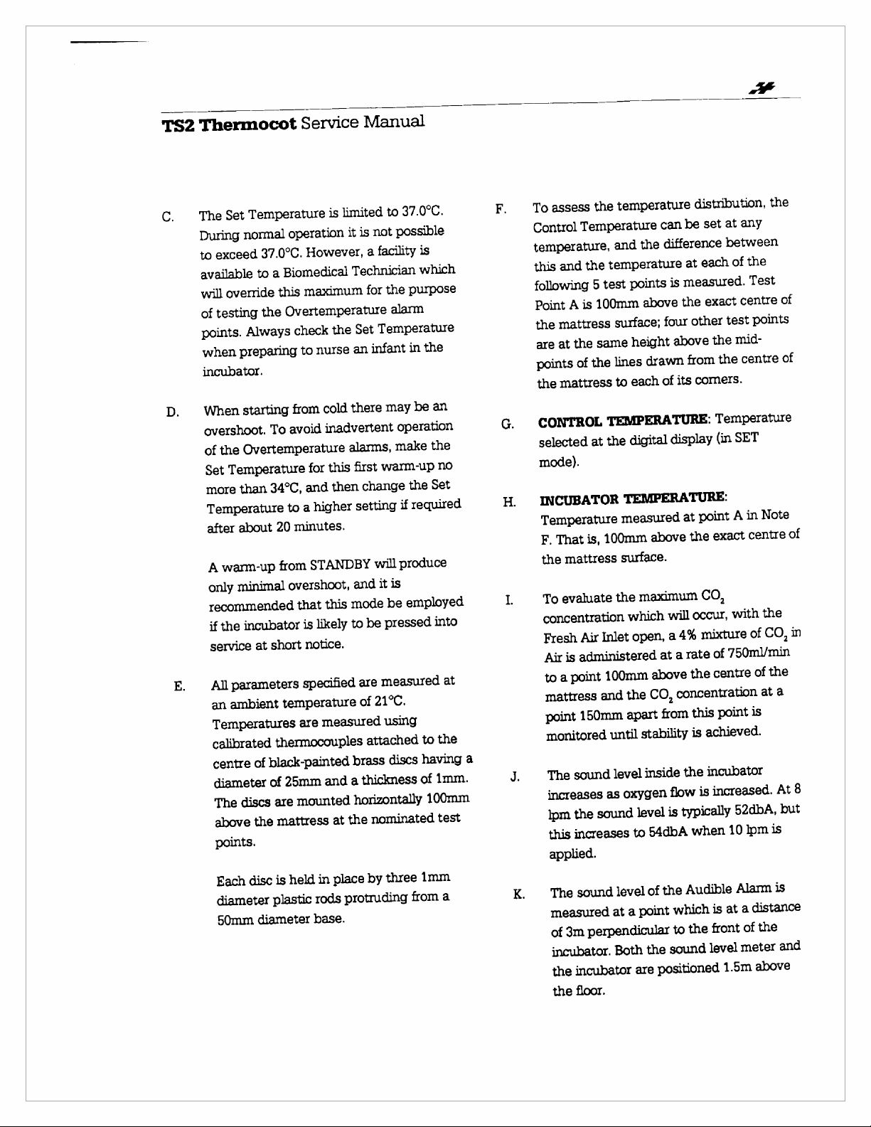
C.
D.
E.
Thermocot
Temperature
Set
The
During
to
available
will
normal
exceed
to
override
testing
of
points.
when
incubator.
Always
preparing
starting
When
overshoot.
Overtemperature
the
of
Temperature
Set
than
more
Temperature
about
after
warm-up
A
minimal
only
recommended
incubator
the
if
service
All
an
Temperatures
calibrated
centre
at
parameters
ambient
of
diameter
discs
The
the
above
points.
disc
Fach
diameter
50mm
diameter
Service
is
operation
37.0°C.
the
However,
Biomedical
a
maximum
this
Overtemperature
check
nurse
to
cold
from
inadvertent
avoid
To
this
for
and
34°C,
higher
a
to
minutes.
20
STANDBY
from
overshoot,
this
that
likely
is
notice.
short
specified
temperature
measured
are
thermocouples
black-painted
and
25mm
of
mounted
are
mattress
in
held
is
rods
plastic
base.
Manual
limited
not
is
it
facility
a
Technician
for
Temperature
Set
the
infant
an
there
alarms,
first
change
then
setting
will
it
and
mode
be
to
are
21°C.
of
attached
brass
thickness
a
horizontally
nominated
the
at
by
place
protruding
37.0°C.
to
possible
is
which
purpose
the
alarm
the
in
be
may
operation
make
warm-up
the
required
if
produce
is
employed
be
pressed
measured
using
to
having
discs
of
1mm
three
from
an
the
no
Set
into
at
the
1mm.
100mm
test
a
à
the
assess
To
Control
temperature,
this
following
Point
the
are
points
the
Temperature
the
and
5
100mm
is
A
mattress
same
the
at
the
of
mattress
CONTROL
selected
mode).
INCUBATOR
Temperature
F.
the
To
concentration
Fresh
Air
to
mattress
point
monitored
The
increases
lpm
this
applied.
at
is,
That
mattress
evaluate
Inlet
Air
administered
is
point
a
and
150mm
sound
sound
the
increases
sound
The
measured
perpendicular
3m
of
incubator.
incubator
the
the
floor.
temperature
can
difference
the
and
temperature
is
points
test
above
surface;
lines
to
TEMPERATURE:
the
100mm
the
100mm
until
level
as
level
at
Both
four
height
drawn
of
each
display
digital
TEMPERATURE:
measured
above
surface.
maximum
will
which
a
open,
at
above
CO,
the
from
apart
stability
inside
level
54dbA
to
the
of
point
the
positioned
are
flow
is
sound
oxygen
a
distribution,
any
at
set
be
between
the
of
each
at
measured.
exact
the
other
above
from
corners.
its
point
at
the
Test
centre
points
test
mid-
the
centre
the
Temperature
SET
(in
Note
in
A
centre
exact
CO,
the
with
occur,
CO,
mixture
4%
rate
a
the
concentration
this
achieved.
is
incubator
the
is
typically
when
Audible
which
the
to
of
750m1/min
of
of
centre
at
is
point
increased.
52dbA,
lpm
10
Alarm
distance
a
at
is
the
of
front
meter
level
above
1.5m
the
of
of
of
in
the
a
At8
but
is
is
and
Page 7
TS2
Thermocot
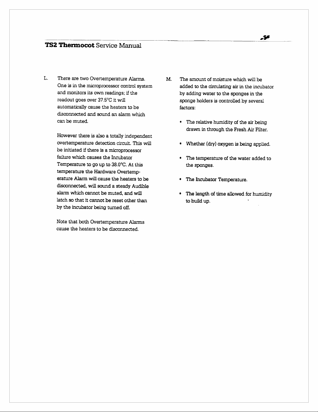
L.
There
One
and
readout
automatically
disconnected
can
However
overtemperature
be
initiated
failure
Temperature
temperature
erature
disconnected,
alarm
latch
by
the
are
two
is
in
the
monitors
goes
be
muted.
there
which
Alarm
which
so
that
incubator
Service
Overtemperature
microprocessor
its
own
readings;
over
37.5°C
cause
the
and
sound
is
also a totally
detection
if
there
is a microprocessor
causes
to
the
cannot
it
the
go
up
to
Hardware
will
cause
will
sound a steady
be
muted,
cannot
being
be
tumed
Manual
control
if
it
will
heaters
an
alarm
independent
circuit.
Incubator
38.0°C.
Overtemp-
the
heaters
and
reset
other
off.
Alarms.
system
the
to
be
which
This
At
this
to
Audible
will
than
will
be
The
added
by
sponge
factors:
+
+
e
e
*
amount
to
adding
holders
The
relative
drawn
Whether
The
temperature
the
sponges.
The
Incubator
The
length
to
build
of
moisture
the
circulating
water
is
humidity
in
through
(dry)
of
up.
which
air
in
to
the
sponges
controlled
of
the
the
Fresh
oxygen
Temperature.
time
of
the
allowed
is
being
water
will
the
by
several
air
Air
for
'
in
be
incubator
the
being
Filter.
applied.
added
to
humidity
Note
cause
that
the
both
Overtemperature
heaters
to
be
disconnected.
Alarms
Page 8

TS2
Thermocot
Service
Manual
Warning
statements
(A
is a possibility
operator.)
WARNING
of a source
or
cause
WARNING
detailed
Incubator
any
withdrawn
WARNING
should
operation
qualified
the
equipment.
WARNING
presence
possible
these
WARNING
in
patient's
minutes.
WARNING
move
When
loss.
WARNING
the
Warning
an
portion
known
the
incubator
Statement
of
Do
not
place
of
radiant
electric
the infant
Complete
All
Do
conditions.
Do
incubator
The
the
Do
radiator.
in
this
into
service.
of
the
from
personnel
be
thoroughly
and
under
medical
risks
not
use
of
flammable
explosion
not
leave
temperature
canopy
infant
it
is
raised
not
leave a patient
while
the
Manual
is
injury
to
the
incubator
heat
Such
to
overheat.
Checkout
before
If
procedure
service.
using
familiar
the
personnel
and
benefits
the
incubator
anaesthetics;
hazard
the
patient
for
long
at
should
in
or
out
there
is
the
used
when
the
patient
in
such
as
exposure
Procedure
placing
the
incubator
it
must
the
incubator
with
direction
familiar
of
using
in
exists
under
unattended
periods.
least
only
of
significant
canopy
Check
every
be
raised
the
incubator.
unattended
is
there
or
the
path
sunlight
may
the
fails
be
its
of
with
the
the
a
the
30
to
heat
raised.
the
as
in
WARNING
does
pressure
measurements
the
concentrations
environment
concentrations
retrolental
below
infants.
WARNING
measured
flowmeter.
should
infant's
WARNING
the
service
incubator
WARNING
the
WARNING
increase
incubator.
WARNING
dependent
air
openings
mattress.
proper
air
build-up.
triggered.
The
concentration
not
predictably
of
oxygen
regulation
40%
If
be
When a system
incubator
If
patient.
The
Proper
circulation.
air
temperature
of
is
fibroplasia.
can
oxygen
with a pressure
The
monitored
head.
should
and
the
to
ensure
an
alarm
administration
the
noise
temperature
upon
Do
at
the
Obstruction
circulation,
An
air
of
inspired
determine
in
the
blood;
are
extremely
inspired
when
necessary.
can
be
is
applied
concentration
infant
is
level
continuous
not
ends
control
circulation
oxygen
an
oxygen
High
increase
Even
dangerous
its
compensated
at a position
fail
alarm
be
removed
shifted
continuity
muted
closely
of
within
control
cover
and
sides
could
loss
of
and
alarm
oxygen
the
partial
blood
gas
important
enriched
oxygen
the
risk
of
concentrations
to
some
flow
should
of
oxygen
near
the
is
activated,
from
to
another
of
care.
monitor
oxygen
unobstructed
air
lead
heat,
carbon
will
the
is
circulation
of
the
to
loss
of
loss
of
dioxide
may
be
for
be
Page 9
TS2
Thermocot
Service
Manual
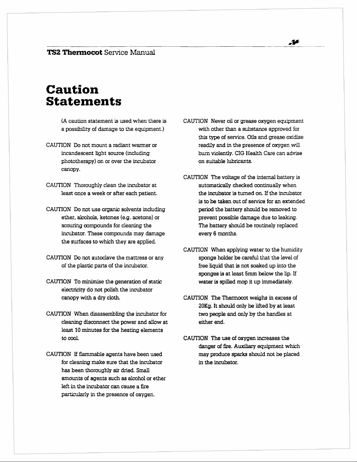
Caution
Statements
{A
CAUTION
CAUTION
CAUTION
caution
a
possibility
incandescent
phototherapy)
canopy.
least
ether,
scouring
incubator.
the
CAUTION
of
the
CAUTION
electricity
canopy
CAUTION
cleaning
least
to
cool.
CAUTION
for
cleaning
has
amounts
left
in
particularly
statement
of
Do
not
mount a radiant
Thoroughly
once a week
Do
not
use
alcohols,
compounds
These
surfaces
Do
To
When
10
If
been
to
not
autoclave
plastic
minimise
do
with a dry
disassembling
disconnect
minutes
flammable
make
thoroughly
of
agents
the
incubator
in
damage
light
on
or
clean
organic
ketones
compounds
which
parts
the
not
polish
for
agents
sure
the
presence
is
used
to
source
over
the
or
after
solvents
(e.g.
for
cleaning
they
the
of
the
generation
the
cloth.
the
power
the
heating
that
air
dried.
such
as
can
cause a fire
the
warmer
(including
the
incubator
each
are
mattress
incubator.
incubator
the
have
the
alcohol
of
when
there
equipment.)
or
incubator
at
patient.
including
acetone)
may
incubator
been
Small
oxygen.
or
the
damage
applied.
or
any
of
static
and
allow
elements
used
incubator
or
ether
is
for
at
CAUTION
with
this
readily
burn
on
CAUTION
automatically
the
is
period
prevent
The
every 6 months.
CAUTION
sponge
free
sponges
water
CAUTION
20Kg.
two
either
CAUTION
danger
may
in
Never
other
type
and
violently.
suitable
The
incubator
to
he
taken
the
possible
battery
When
holder
liquid
is
is
spilled
The
It
should
people
end.
The
of
produce
the
incubator.
oil
or
grease
than a substance
of
service.
in
lubricants.
voltage
battery
should
applying
that
at
Thermocot
and
use
fire.
Oils
the
presence
CIG
Health
of
the
checked
is
turned
out
of
service
should
damage
be
water
be
careful
is
not
soaked
least
5mm
mop
it
weighs
only
be
only
by
of
oxygen
Auxiliary
sparks
should
continually
on.
routinely
up
lifted
oxygen
and
internal
that
below
the
increases
equipment
equipment
approved
grease
of
oxygen
Care
can
battery
If
the
incubator
for
an
be
removed
due
to
leaking.
replaced
to
the
humidity
the
level
up
into
the
immediately.
in
excess
by
at
handles
not
be
for
oxidise
will
advise
is
when
extended
to
of
the
lip.
If
of
least
at
the
which
placed
Page 10
TS2
Thermocot
Service
Manual
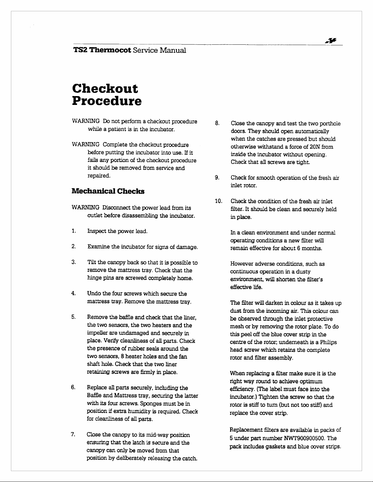
Checkout
Procedure
WARNING
while a patient
WARNING
before
fails
it
should
repaired.
Mechanical
WARNING
outlet
1.
Inspect
2.
Examine
3.
Tilt
remove
hinge
4.
Undo
mattress
5.
Remove
the
impeller
place.
the
two
shaft
retaining
6.
Replace
Baffle
with
position
for
Do
not
perform a checkout
is
Complete
putting
any
portion
Disconnect
before
the
the
canopy
the
pins
the
the
two
sensors,
are
Verify
presence
sensors, 8 heater
hole.
all
and
its
four
if
cleanliness
the
the
of
be
removed
Checks
the
disassembling
power
the
incubator
back
mattress
are
screwed
four
screws
tray.
Remove
baffle
the
undamaged
cleanliness
of
rubber
Check
that
screws
are
parts
securely,
Mattress
screws.
extra
humidity
of
all
in
the
incubator.
checkout
incubator
the
checkout
from
power
lead.
for
so
that
tray.
completely
which
the
and
check
two
heaters
and
of
seals
holes
the
two
firmly
tray,
securing
Sponges
is
parts.
procedure
procedure
into
use.
procedure
service
signs
Check
mattress
all
in
including
and
lead
from
the
incubator.
of
damage.
it
is
possible
that
home.
secure
that
the
and
securely
parts.
around
and
the fan
liner
place.
the
must
be
required.
If
it
its
the
the
tray.
liner,
the
in
Check
the
the
latter
in
Check
to
8.
9.
10.
be
mesh
this
centre
head
rotor
When
night
efficiency.
incubator.)
rotor
replace
Close
the
canopy
doors.
They
when
the
catches
otherwise
inside
Check
Check
inlet
Check
filter.
in
place.
In a clean
operating
remain
However
continuous
environment,
effective
The
dust
observed
withstand a force
the
incubator
that
all
for
smooth
rotor.
the
condition
It
should
environment
conditions a new
effective
adverse
operation
life.
filter
will
from
the
or
by
removing
peel
off
the
of
the
screw
which
and
filter
replacing a filter
way
round
(The
Tighten
is
stiff
to
the
cover
and
should
are
screws
operation
be
clean
for
conditions,
will
shorten
darken
incoming
through
blue
rotor;
underneath
retains
assembly.
to
achieve
label
turn
(but
strip.
test
the
two
open
automatically
pressed
without
are
of
the
and
about 6 months.
in a dusty
in
the
the
cover
make
must
the
screw
of
opening.
tight.
of
fresh
and
securely
under
filter
the
colour
air.
This
inlet
rotor
strip
the
sure
optimum
face
not
too
but
20N
the
air
such
filter's
as
colour
protective
plate.
in
is a Philips
complete
into
so
stiff)
porthole
should
from
fresh
inlet
held
normal
will
as
it
takes
To
the
it
is
the
the
that
the
and
air
up
can
do
7.
Close
the
canopy
ensuring
canopy
position
that
can
only
by
deliberately
the
to
latch
be
moved
its
mid-way
is
releasing
secure
from
position
and
the
that
the
catch.
Replacement
5
under
part
pack
includes
filters
number
gaskets
are
available
NWT900900500.
and
blue
in
packs
cover
of
The
strips.
Page 11
TS2
Thermocot
Service
Manual
Operational
TA
Fs
Fs
Ta
т,
1.
Following
make
place
air
filter.
open
Put
the
position.
unconnected
audible
Turn
power
Put
the
position.
of
all
into
the
light
should
light
should
other
be
off.
There
alarm
Mode
cancelled
should
There
mode.
should
should
been
Push
the
Operational
of
all
displays
that
all
digital
Checks
the
sure
that
inchiding
Put
the
position.
main
ON/OFF
If
the
there
Power
OFF
the
lead.
main
ON/OFF
There
displays
STANDBY
be
be
lights
and
should
to
having
should
repaired.
be
draw
been
by
pushing
come
on.
be
If
there
be
investigated
not
be
used
ON
button
mode.
should
lamps
and
display
above
mechanical
all
parts
the
mattress
fresh
switch
power
lead
should
Fail
alarm.
incubator
switch
should
before
the
mode - the
on
flashing
on
but
there
the
digital
an
intermittent
attention
selected
MUTE.
no
alarms
are
any alarms,
until
to
Again
be
all
segments
are
illuminated.
checks
are
securely
and
the
air
inlet
rotor
to
the
is
still
be a continuous
and
connect
to
the
be
an
automatic
incubator
Standby
and
the
should
display
audible
to
the
Standby
and
this
No
Mute
in
the
Standby
their
and
the
incubator
the
condition
enter
the
an
automatic
initiated.
Check
of
the
in
fresh
in
the
ON
the
ON
test
goes
heater
be
no
should
can
light
cause
has
test
be
Push
display
light
Push
Set
Release
of
the v (down)
Note
selected.
incubator
ON/OFF
fail
and
in
the
that
was
10.
Push
displays
Alarm
11.
Tum
switch.
should
Select
temperature - it
selected
12.
Allow
stabilised
This
blinking.
at
this
alarms.
13.
Select
and
60
minutes.
alarms.
the A (up)
the
Set
should
be
the
button
temperature
the
button
the
Set
temperature
Tum
at
the
switch.
alarm.
Restore
check
that
Operational
the
Set
temperature
selected.
the
TEST
should
should
off
Operational
the
will
temperature.
the
allow
the
incubator
After
come
in
9.
incubator
at
the
be
indicated
Run
maximum
the
Again,
sound
15
on
the
incubator
button
temperature.
off
button.
off
the
button.
be
in
should
momentarily
and
the
continuously
up
in
0.1
increments.
and
check
you
the
power
power
source,
There
should
power
after
incubator
mode
(not
is
All
briefly
lit.
briefly.
at
the
minutes
selected
incubator
turn
Standby
mode
and
be
to
run
Set
by
the
There
temperature,
to
there
should
The
“Actual”
“Set”
light
to
move
the
function
have
to
the
not
at
be a power
15
seconds,
has
resumed
Standby)
the
same
lamps
and
The
Audible
ON/OFF
it
on
again;
mode.
check
the
the
same
until
it
has
temperature.
Heater
for
60
minutes
should
be
37.0°C,
run
for
another
be
no
to
on.
the
its
and
as
Set
as
was
light
no
it
The
digital
display
air
temperature,
on,
and
the
There
should
the
Actual
be
no
should
heater
light
above
alarms.
show
light
incubator
should
the
display.
be
Page 12
TS2
Thermocot
Service
Manual
Electronics
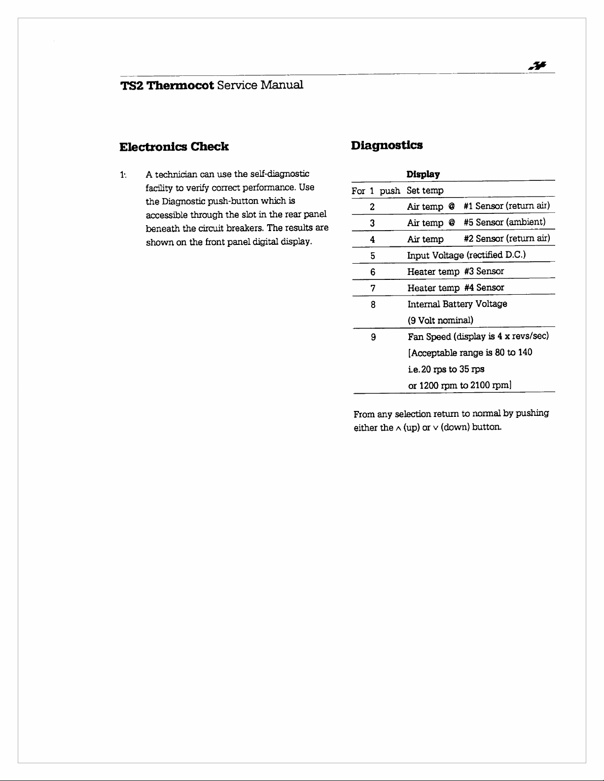
1.
A
technician
facility
the
Diagnostic
accessible
beneath
shown
to
verify
the
on
Check
can
correct
push-button
through
circuit
the
front
use
the
performance.
the
slot
breakers.
panel
self-diagnostic
Use
which
is
in
the
rear
panel
The
results
digital
display.
are
Diagnostics
For 1 push
2
|
lola
From
any
either
Display
Set
Air
Airtemp
Air
Input
Heater
Heater
Internal
selection
the A (up)
temp
temp © #1
@
temp
Voltage
temp
temp
Battery
(9
Volt
nominal)
Fan
Speed
[Acceptable
Le.20
rps
to
or
1200
rpm
retum
or v (down)
Sensor
#5
Sensor
#2
Sensor
(rectified
#3
Sensor
#4
Sensor
Voltage
(display
range
is
35
rps
to
2100
to
normal
button.
(return
(ambient)
(return
D.C.)
is 4 x
80
rpm]
by
air)
air)
revs/sec)
to
140
pushing
Page 13
.
TS2
Thermocot
Service
Front
Canopy
PEN:
Manual
Catch
SE
Infant
Restraint
Harness
O
On/Off
“> “>
switch
Fresh
air
mlet
Control
panel
«ad
db
Oxygen
inlet
nipple
Page 14
チン
TS2
Thermocot
Service
Manual
CAUTION
HIGH
OXYGEN
To
increase
corcentrator.
Oxygen
(via
40%
ar
oxygen
No
oxygen
appty
Te)
at
ripple
at
det
enc:
With
oxyger:
increased
by
closing
inlet
using
analyser
not
close
nel
no
sources
near
applied.
may.
over.
fresh,
ah
trash
oxygen
of
concentrations
be
Mondor
Do
ar
anche
Anion
neubator
Re;
ee
ее
4
」
7
a
-
RR
9
DED.
^
22
ys
の
2%
^
ЕВ:
ЕР
~
ag
ge
9
ON
Le 2 s
%
o
Е
-
~
5
42200
OE
GUS,
~
E
SINS
SØG
2
TR x eee
4
の
ASE
20
a
paro
>
DİM
22
295
ASG).
À
&
Page 15

TS2
Thermocot
Service
Manual
Cleaning
WARNING
WARNING
CAUTION
CAUTION
CAUTION
Disconnect
outlet
Allow
incubator
handling
Do
ether,
scouring
incubator.
the
surfaces
To
electricity
dry
cloth.
If
for
cleaning,
been
thoroughly
assembly.
Disassembly
1.
Make
sure
before
disassembling
at
least
has
been
the
heaters.
not
use
alcohols,
compounds
These
to
minimise
do
not
flammable
make
Procedure
the
incubator
the
10
switched
organic
ketones
compounds
which
the
polish
agents
sure
air
dried
power
for
lead
the
minutes
off
solvents
(e.g.
acetone)
cleaning
may
they
are
generation
the
canopy
have
been
that
all
before
is
turned
from
its
incubator.
after
the
before
including
or
the
damage
applied.
of
static
with
used
parts
have
re-
off.
a
Check
to
touch.
The
the
7mm
Cleaning
10.
All
removed
only
Do
not
coarse
The
clean.
The
the
two
immersed
wipe
11.
The
brush
antiseptic
Do
not
coarse
that
the
Remove
liner
may
two
retaining
Nut-driver
parts
antiseptic
use
alcohols,
polish.
mattress
Do
not
Mattress
heaters
if
necessary.
clean.
canopy
may
or
cloth
soap
use
alcohols,
polishes.
two
heaters
both
be
removed
screws
is
required.
should
soap
can
be
immerse
Tray,
the
and
be
scrubbed
and
wiped
and
warm
ether,
heaters.
for
are
be
and
warm
ether
or
scrubbed
the
mattress.
Baffle,
the
Liner
Scrub
clean.
water.
ketones
are
not
too
cleaning
removed.
cleaned
ketones,
them
with a soft
water.
and
the
Impeller,
can
all
Use
using
wiped
and
only
or
hot
if
A
or
be
an
2.
Disconnect
outlet.
3.
Open
4.
Undo
tray.
mattress.
5.
Remove
tray.
6.
Remove
7.
Remove
the
power
the
canopy
the 4 screws
Remove
the
the
the
the
sponges
baffle.
impeller
lead
to
its
retaining
tray,
the
from
from
from
fully
screws
the
the
the
back
position.
the
mattress
mattress
motor
power
and
shaft.
the
With a slightly
seals
fan
13.
Remove
and
needs
discoloured a new
Wipe
slightly
14.
With a damp
contains
or
similar
tube
on
the
shaft
to
remove
the
Air
the
filter.
replacing - if
the
rotor
damp
the
technique,
and
its
top
damp
sensors,
any
inlet
Check
it
filter
and
filter
cloth.
cloth,
wipe
filter,
and,
gasket.
cloth
wipe
the
heaters
deposits.
rotor,
the
filter
the
filter
to
is
excessively
is
required.
panel
with
the
area
using a bottle
the
air
entrainment
the
and
see
a
which
rubber
the
panel,
if
it
brush
Page 16

TS2
15.
16.
Thermocot
Before
re-assembling
make
sure
of
soap
or
Replace
that
sure
Push
screws
should
Make
clean
rotor
tum.
position;
be
all
in
which
that
on
the
which
be
sure
air
side
should
Leave
showing.
other
the
firm,
the
that
they
deposits.
parts
in
they
heaters
impeller
retain
but
the
filter
towards
be
firm,
the
rotor
red
warning
Service
the
are
quite
the
reverse
were
removed.
are
as
far
the
mattress
not
over
is
installed
the
but
not
in
the
Manual
removed
dry
and
order
Make
firmly
seated.
as
it
will
tray
tightened.
with
incubator.
too
hard
fresh
air
label
should
parts,
free
to
go.
The
the
The
to
not
17.
18.
19.
Replace
Before
incubator
make
correctly
With a damp
surfaces
control
the
being
should
sure
carried
to
panel.
mattress
declared
be
that
the
out.
cloth
remove
and
close
fit
for
service,
briefly
operated
re-assembly
wipe
all
extemal
grime.
Include
the
has
the
canopy.
the
to
been
front
Page 17

TS2
Thermocot
Service
SIRIA
PES
Е
AO
な
ES
o
LESSE
Boe
の
Manual
2.15
ος
EZIO
RE
か
か
の
の
SOLITA
o
RÁNA
κο
μα
En.
eM
NS
Heaters
des
ee
removed,
showing
sitio
SORES
2
Dro:
impeller, 2 sen
A
クン ク 244
DITS
7
И
АИ
~
SOOS
SRM
RA,
a>
ЛЯ
ジン
И
SR
ES
RO
S
577
SOIS
Rox
グン
НЕЕ
SU
Page 18

TS2
Thermocot
Alarms
Power
Failure
Low
Voltage
System
Failure
Fan
Service
Caused
Removal
when
cot
Input
Voltage
below
Fan
less
by:
of
power
switched
normal
than
Manual
12.5%
60%
on
Visible
Alarm
None
Flashing
Flashing
Audible
Alarm
Steady
Flashing
Flashing
Mute
No
15
min
15
min
Mute
Heaters
x
No
action
No
action
Digital
display
(Push
None
|
Normal
|
Normal
Test)
Heater Heater
Sensor
Internal
Battery
Control
Over
Standby
Initiated
temp
Temp
Software
Hardware
Mode
|
of
normal
temp
not
Error
in
five
sensors
Voltage
Air
temp
1°C
from
Air
Temp
Air
temp
Cot
tumed
Main
Switch
RPM
current
correct
one
of
below
more
set
temp
over
over
38°C
on
at
or
the
7.5
volt
than
37.5°C
Flashing
Flashing
None
None
(Standby
Flashing
|
Flashing
Steady
Flashing
15
|
15min
N/A
|
Continuous
min
|
No
action
Cut
off
reset
36°C
Cut
off
Manual
reset
On
at
|
Normal
Normal
N/A
None
(FAn)
(HEA)
(SEn)
(bAt)
light
flashing)
Page 19

TS2
Thermocot
Service
Technical
Description
The
TS2
Thermocot
which
supplies
air
around
nursing
CAUTION
This
Temperature
be
routinely
Underneath
heaters.
down
and
two
nursing
CAUTION
Ensure
blocked
Fresh
If
the
fresh
helping
carbon
positive
any
and
it
staff.
incubator
Return
to
the
rear
of
heaters
area
that
by
Air
fresh
filtered
to
minimise
dioxide.
pressure,
gaps
which
doors.
Oxygen
The
fresh
air
desired
patient's
concentration
flow
continuously
placing
fresh
into
dioxide
to
apply
environment
rate
of
the
air
inlet
the
incubator
build-up.
at a temperature
monitored.
the
fan
the
and
the
blankets,
air
oxygen,
sensor
is a lightweight
warmth
does
not
and
the
infant’s
mattress
air
from
through
mattress.
the
warmed
through
air
inlet
monitor
is
the
vent
holes
sheets
inlet
is
is
added
the
The
circuit
and
there
should
pure
achieved
and
near
closed
there
to
have
the
open,
some
may
oxygen
above
will
the
without
Manual
incubator
an
infant
by
which
is
Servo
Control
temperature
are a fan
the
It
then
end
and
to
accumulation
thus
be
only
time.
oxygen
the
is a danger
and
patient
or
more
the
be a factor
patient’s
vicinity
vent
holes
is
passed
air
re-enters
slots.
end
slots are
any
other
than
circulating
acquires a slight
air
escapes
around
be
closed
and
raise
40%
oxygen.
It
is
important
concentration,
oxygen
of
circulating
set
by
the
of
Skin
should
two
passes
in
the
front
over
the
not
materials.
10
Ipm
of
air,
of
expired
through
the
canopy
if it
is
the
The
of
the
input
to
head.
If
the
being
fed
carbon
the
If
oxygen
the
limited.
is
applied
concentration
Humidity
As
the
recently
area
through
humidity
wet
the
water
through
spill
any
sponges
use a syringe
sponges.
sponges
into
the
the
water.
to
the
holders
sponges.
add
to
Circulation
After
the
warmed
goes
up
along
the
attracted
mode
advantages - the
reducing
the
thus
CAUTION
It
is
the
air
Electronics
The
electronically
which
functions
to
Temperature,
audible
procedure.
down
of
air
movement
radiant
air
velocity
reducing
important
mattress - any
circulation
operation
is
operate.
evaporative
patterns.
by a microprocessor-based
relatively
it
performs,
The
turn
alarms
The
with
the
fresh
achieved
warmed
end
If
by
Either
water,
add
air
skin
into the
canopy
heat
around
to
keep
blockage
of
the
sophisticated
user
the
and
microprocessor
in
the
air
re-enters
slots,
it
passes
elevated
putting a small
and
Do
remove
or
water
passes
losses
heaters
but
is
perform a rudimentary
allowing
not
leave
to
of
the
retum
has
two
is
kept
the
infant
heat
clear
quite
able
unit
humidity
overfill
and
the
out
canopy
from
the
can
and
only
ON
air
inlet
incubator
the
nursing
over
the
is
amount
it
to
soak
the
holders
soak
the
them
in
place
holders.
of
the
end
before
air
vents.
This
significant
warm,
thereby
the
infant;
is
relatively
losses.
vent
holes
interfere
fan
is
controlled
in
the
variety
simple
for
to
adjust
and
OFF,
is
all
the
time
open,
is
required,
of
up
or
and
slots,
it
being
and
low,
around
with
the
system
of
the
user
the
Set
mute
test
Page 20

TS2
Thermocot
Service
Manual
scanning 5 temperature
sensor,
battery
operation.
microprocessor
of
calculations
heater
conditions
Alarms
Refer
causes
In
is
sounds.
light.
restoration
Most
accompanied
alarm.
minutes
indicates
When
mode
There
The
37.5°C
functioning
Over
Hardware
triggered
and
any
heater
voltage
the
information
power
to
the
and
the
event
switched
It
The
other
The
by
that
the
is
cancelled.
are
first
activates
and
Temperature
if
this
is
other
normal
power,
and
monitoring
As
it
runs
through
is
constantly
it
is
and
decisions,
and
fan
are
detected,
Alarms
effects
of a power
on,
is a steady
alarm
of
alarms
audible
pushing
alarm
two
if
correctly - this
Overtemperature
the
independent
Chart
of
fault
the
Power
tone,
can
only
power
or
come
by a similarly
alarm
the
the
Mute
condition
types
of
if
the
the
microprocessor
Alarm.
air
temperature
control
sensors, a fan
input
voltage,
its
own
its
program,
checking
receiving,
speed.
alarms
failure
be
turning
on
can
Mute. A flashing
mode
Over
air
of
circuitry.
making
and
controlling
If
any
fault
are
initiated.
for a quick
conditions.
while
Fail
audible
and
there
cancelled
off
the
as
flashing
modulated
he
cancelled
has
been
is
cleared,
Temperature
temperature
itself
is
called
the
There
is
also
Alarm
which
exceeds
the
microprocessor
speed
internal
correct
the
the
validity
the
guide
to
(Page
19)
the
incubator
alarm
is
no
alarm
by
incubator.
red
lights
audible
for
red
selected.
the
Mute
alarm.
exceeds
is
Software
a
is
38.0°C,
the
15
light
and
Whereas
will
36.0°C
Hardware
heaters,
only
Immediate
Overtemperature
A
supply
i.e.
The
air
Set
heaters
incubator's
the
be
A
failure
of
attended
be
transferred
cause
pushing
current,
could
(HEA),
(bAt).
If
there
be a continuous
the
reset
itself
and
restore
Overtemperture
gives a Steady
be
reset
attention
Low
Voltage
voltage
on a 12
temperature
temperature,
situation.
required.
System
nursing
withdrawn
volt
Control
Temp
and
fan
control
The
alarm
with
the
staff,
to
by a technician.
to
of a System
the
Test
and
reading
be
sensor
fan
failure
is a total
Software
by
However,
from
another
Overtemperature
when
the
power
audible
tuming
is
required
Alarm.
alarm
indicates
is
12.5%
below
supply,
is
continue
incubator,
which
failure
down
alarm
more
than
either
above
system
nursing
Audible
indicates
should
service,
as
alarm
button,
the
(SEn), a heater
(FAn)
or a flat
control
audible
system
alarm
incubator
to
the
Alarm
alarm
off
the
incubator.
for
that
its
to
10.5
indicates
1.0°C
or
to
run,
will
attempt
intervention
alarm
can
that
there
outside
be
The
and
the
soon
as
can
be
diagnosed
while
the
message
internal
failure,
and
alarm
cools
to
heaters,
nominal
below.
and
immediately
incubator
possible.
the
locks
out the
and
can
either
the
incoming
value
volts.
that
the
away
from
The
the
to
remedy
be
muted.
has
been
of
the
control
should
patient
The
by
alarm
is
displayed.
failure
battery
there
no
displays.
Actual
the
may
a
It
will
Page 21

TSZ
Thermocot
Service
Manual
Display
The
digital
display
shows
the
actual
infant.
Calculations
microprocessor
temperature
accurately
nursing
Set
Temperature
To
read
(A)
or
reading,
seconds
Temperature
digital
Actual
Test
Pushing
causes
operator
Alarm
alarm,
diagnostic
known
area.
the
the
Down
touch
and
display
air
temperature
the
all
the
can
is
also
pushing
message
sensors
Set
hold
Test
see
Standby
When
the
incubator
automatically
condition
temperature
operate,
air
Standby
alarm
pushing
ready
associated
is
not
the
thus
drawn
light
which
Mute.
for
immediate
with
is
on
the
air
temperature
performed
on
readings
allow
without
Temperature,
(v)
touch
the
appropriate
it
until
is
reached.
indicate
displays
tested.
the
into
heaters
regulated.
saving
flashes,
can
The
whether
or
button
to
if
any
are
When
Test
to
be
is
first
Standby
are
wear
through
and
be
permanently
incubator
use,
full
operation.
front
panel
normally
around
by
the
from
the
5
this
temperature
having a sensor
push
either
button.
the
The
the
during
be
button
activated,
the
without
To
button
desired
lights
above
the
reading
Set
temperature.
normal
activated,
faulty.
The
there
is a System
causes
displayed.
switched
mode.
In
The
fan
does
on
the
fan
inlet
filter.
there
is
an
cancelled
is
thus
the
Warm
change
Set
on
this
and
the
to
in
the
the
for
2
the
is
operation
so
that
Audible
an
alarm
it
goes
their
not
motor,
The
audible
by
kept
warm,
wear
up
time,
be
the
Up
the
the
and
through
about
mode,
is
switch
use
15%
of
push
necessary
on.
the
Memory
When
the
incubator
intentionally
is
pulled
out
Temperature
or
Operational,
temporary
time,
in
Standby
sounding,
default,
Power
The
supply
12v
disconnect
the
of
anticlockwise
Now
new
clockwise
make
Filter
The
replaced
dark,
flow.
environments,
filter
memory
restoration
mode,
and
32.0°C
Supply
TS2
Thermocot
voltages;
d.c.
To
change
the
incubator
attach
power
until
any
other
fresh
air
every
seems
or
If
the
incubator
more
frequently.
of
this
Standby
normal.
On
button.
to
switch
or
by
accident
or
there
and
the
are
automatically
for
of
power
with
the
Set
until
240v
from
power
by
the
until
power
the
supply,
it
is
adjustments.
inlet
filter
months,
6
be
to
will
it
mode,
To
go
to
To
off
the
is
switched
(e.g.
is a power
mode
of
about
will
an
audible
Temperature
reset
is
it
will
operate
a.c.,
115v
one
supply
at
cable
screwing
connector
cable
screwing
tight.
It
is
should
when
or
restricting
is
used
necessary
be
is
reduced
full
Operational
revert
to
Standby
incubator
failure),
operation,
one
set
by
the
the
designated
the
not
be
in
and
off,
either
the
power
the
Standby
stored
in
hour.
After
the
incubator
alarm
will
be,
Operator.
the
from 4 different
a.c.,
24v
d.c.,
to
another,
hand
right
retaining
away.
comes
for
retaining
necessary
routinely
noticeably
is
it
fresh
inlet
dusty
change
to
to
it
then
cord
Set
this
by
and
end
ring
the
ring
to
air
the
Page 22

TS2
Thermocot
Routine
Maintenance
Every
cleaning
Mechanical
—
2
3
4
5
Listen
6
Check
need
Six
Change
Check
the
dirty.
or
Check
for
plastic
in
Iscanopy
parts,
canopy
for
fan
no
Months
(q.v.)
the
filter.
seals-still
damage-look
split
or
doors.
latch
o.k.?
excessive
speed
(on
maintenance
Service
Manual
Technical
-
apart
in
place,
for
in
mattress,
noise.
diagnostics);
(do
chips
not
from
cracked
or
cracks
chips
motor
oil).
or
or
cracks
split,
in
should
Calibration
Procedure
There
are
are
only
two
be
made-
one
for
the
Incubator
align
with
the
digital
readout,
the
Hardware
The
Incubator
point
100mm
mattress
black-painted
1mm
thick,
Set
the
incubator
stabilized,
the
cerice
readout
Temperature.
of
37.0°C
necessary.
Overtemperature
Temperature
above
using
a
brass
aligned
adjust
of
the
is
the
same
Check
and
33.0°C
the
thermocouple
disk,
horizontally.
to
run
the
calibration
incubator)
as
the
and
calibration
Temperature
and
is
measured
exact
centre
attached
25mm
in
at
34.0°C.
pot
so
that
the
Incubator
calibration
make
adjustments
adjustments
the
other
alarm.
at
of
the
to
diameter
When
it
(closest
the
digital
at
Set
points
to
to
for
a
a
and
has
to
if
7.
Canopy
8
Self
9
Are
10
Is
11
Measure
12
Check
13
Replace
14
Carefully
incubator
fluff.
door
test.
heaters
impeller
earth
over-temp.
on-board
vacuum
to
function
secure?
secure
ieakage,
ren-ove
-
adjust
on
shaft?
operating
battery
clean
inside
accumulated
(9
volt).
if
necessary.
currents.
bottom
dust
of
and
To
set
the
overtemperature
stabilize
Then
followed
Set
will
buttons
Incubator
Temperature-
on
should
So
should
is
correct
triggered,
OFF.
re-stabilize
the
push
by
Temperature
commence
so
that
Temperature.
the
brass
have
that
this
happens.
be
at
and
the
Allow
the
at
incubator
the
Diagnostic
the
Test
of
39.0°C
to
rise.
there
as
measured
disc-
reaches
sounded;
about
37.8°C.
consistent.
circuit
can
incubator
36.0°C.
alarm
temperature
button
button
Ideally
Push
is
a
digital
When
38.0°C
adjust
Repeat
Once
only
to
once-
and
one
by
the
the
be
cool
point,
at
36.0°C.
3
times
this
selects
the
temperature
of
the
SET
display
the
Incubator
the
thermocouple
the
alarm
pot
(left
trigger
the
test
the
alarm
reset
by
before
trying
first
of
hand)
point
until
has
turning
a
it
to
Page 23

TS2
Thermocot
Service
Manual
Air
ur
AMBIENT
EMPERA
SENSOR
Flow
Г
|
Diagram
|
p
NOS
LR
&
FRESH
as
|
fr
~
SENSO
2
im,
SEND.
I
LT
>
N
1
|
FHM
m
BB
©
Page 24

‘à
3
TS2
Thermocot
Service
Manual
Circuit
Breakers
Serial
Number
Calibration
Slot
Turn
anti-clockwise
to
release
Page 25

TS2
Thermocot
Parts
Item
1
2
3
4
5
6
7
8
9
10
11
12
13
14
15
16
17
18
19
20
21
22
23
24
25
26
27
28
29
31
32
33
34
35
36
37
38
39
40
41
42
Service
List
Part
9012-002-00
9012-003-00
9012-005-00
9012-004-00
9012-006-00
9013-101-00
9027-018-00
9100-001-00
9012-010
9012-009-00
9012-001-00
9013-102-00
9027-017-00
9001-101-00
9001-102-00
9016-003-00
9015-002-00
9016-001-00
9100-002-00
9100-003-00
9006-000-00
9015-005-00
9015-003-00
9100-004-00
9015-004-00
9100-005-00
9015-001-00
9015-006-00
9020-001-00
9022-000-00
9023-001-00
9026-004-00
9024-001-00
9030-000-00
9026-002-00
9029-000-00
9100-006-00
9100-007-00
9100-008-00
9100-009-00
9016-002-00
9026-005-00
Manual
General
-
No.
-00
Assembly
Description
Hinge
Hinge
Hinge,
Hinge
Hinge
Cable
Cable
Label,
Handle
Cover,
Screw,
Screw,
Front
Label,
Nipple,
Hex
Nut,
Buzzer,
Screw,
Cover,
Sensor,
Liner,
Heater
Baffle
Screw,
Screw,
Washer,
Label,
Infant
Breaker
Breaker
Breaker
Breaker
Breaker
Circ.
Bkt.
Arm
HD.
Soc.
C/W
Circuit
Back
Bkt.
Arm
Assembly,
Assembly,
Power
Right
HD.
Phil.
Slotted
Assembly
Panel
Oxygen
Oxygen
Sonalert
Tap
Self
Hand
Left
Ambient
Screws
C/W
Assembly
Assembly
Slotted
LD.4mm
Head,
Hex
6mm
LD.
Canopy
Restraint
Circuit
Circuit
Circuit
Circuit
Label,
R.H.
R.H.
Screw,
Axle,
Cover,
Panel,
L.H.
L.H.
Sponge
Tray
Thumbscrew
Mattress
Impeller
Washer,
1.0
2.0
20.0
10.0
Assy.
Cap,
End
Breaker
Assy.
12V
240V
Lead
Hand
No.10
Pan
Supply
MC-07-1305
End
Temp.
PanHD.
M6
Release
Hamess
AMP
AMP
AMP
AMP
End
HD.
and
M6
Stops
M4
Hose
Washers
M4
Qty
1
2
1
1
1
1
1
4
1
1
1
1
1
1
1
1
2
1
2
8
1
1
1
1
1
4
1
1
1
2
1
2
1
4
1
1
2
2
4
4
1
1
Page 26

TS2
Thermocot
Service
Manual
General
Assembly
mene
En
SPONGE
&
WASHERS
SENSOR
fiNCL.
mee)
NUTS}
27}
^
LH.
END
22)
LABEL
3
LINER
ASSY.
RH,
6
)BRACKET
SSEMBLY
HINGE
INSERT
(BAFFLE)
MS
[
|
O
7
1
FRONT
ASSY.
RH.
HINGE
8 ) SCREW
PANEL
DRG.
SEE
ARM
ο
(21
an
HARNESS
UM. HINGE
BRACKET
11)
BACK
oe
/
PANEL
ASSEMBLY
—
CON
U
Page 27

TS2
Thermocot
Service
Manual
Parts
Item
1
2
3
4
5
6
7
8
9
10
11
12
13
14
15
16
17
18
19
20
21
22
23
24
25
26
27
28
29
30
31
32
33
34
35
36
37
List
Part
No.
9009-005-00
9009-000-00
9010-000-00
9011-004-00
9100-010-00
9100-011-00
9006-017-00
9006-016-00
9100-012-00
9011-003-00
9011-006-00
9100-013-00
9006-009-00
9006-004-00
9006-101-00
9006-018-00
9100-014-00
9100-015-00
9010-003-00
9010-002-00
9006-001-00
9011-101-00
9017-011-00
9100-016-00
9100-017-00
9017-003-00
9017-002-00
9006-014-00
9100-018-00
9100-019-00
9008-000-00
9006-005-00
9100-020-00
9007-000-00
9006-010-00
9006-011-00
9006-013-00
9006-012-00
-
Front
Panel
Description
of
Pack
Filter
Assembly
AirInlet
Spacer,
Washer,
Nut,
Hex.
Spacer,
Knob,
Canopy
Screw,
Label,
Spring,
Screw,
Seal,
Tube,
VenturiSub-Assembly
VenturiJet
screw,
Nut,
Label,
SteelGauze
Panel,
Rotor
Coupling,
C/W
Screw,
Screw,
Insulator,
Switch,
Label,
Nut,
Washer,
Front
Spacer,
Screw,
Alarm
Label,
Label,
Label,
Label,
Slotted
Blue
Philips
Air
OxygenSupply
slotted
Hex.
High
Front
Inserts
Grub,
Grub,
PowerSwitch
Hex.
PanelPCB
Slotted
Board
Alarm
Touch
Rotor
GeneralInstruction
Assembly
Filters
5
Plate
Assembly
Air
Inlet
LD.6mm
M6
Canopy/Front
Latch
PanHD.M5
Compression
Rnd.
Inlet
Pan
M3
Oxygen
Switch
and
M5
M4
Switch
3PDT
Toggle
M3
LD.
3mm
Threaded,
C'Sunk,
Assembly
Panel
Panel
Instruction
Panel
HD.
HD.
M3
(Bar),
Grub
M3x
M3
M6
Screws
10LG
Qty
1
1
1
1
1
3
1
1
1
1
1
1
1
1
1
2
2
1
1
1
1
1
2
2
1
2
1
4
4
1
5
4
1
1
1
1
1
Page 28

A
—
va
we
co
TS2
to
a
rss
ass
Ms
a
UA
A
A
A
Thermocot
Front
Service
Panel
Manual
Assembly
p
Creer
Lalo
fone
sos
x
ar
ALARM
af
P_C.B.
|
\
WASHER
CONTROL
29 * WASHER
PANEL
P.C.B.
35 ) LABEL
35°
PES
CMT
T
SS
US
一 一 =
=*1/
Olam
EL
,
SE
Е
7
mes
nosnou
LSL
VIEW
m
srov
—
/
B
DE
=
LABEL ) spacer
a
MEL
RN
So
SCREW
SCREW
|
34
一、
fd
Él
SPACER
η
|
| | ο
ED
AS
~
(32)
/
(GS
NL
SECTION
0-5
D
AA
WASHER
SPACER
©
FAI
PLATES
FİLTER
<
~
(2)
7
KU
5
N
NOR
L/S
!
1
SS
CTO
è
IN 그 X
E
(Ri
at
Ἡ
로
기
|
4
で
s
이
SCREW
SCREW
TO
ABOUT
GM
BAR
της
(22)
(23)
(14)
_SECTION
B-
ROTOR
ASSEMBLY
JOINING
Smm
4mm
FX
SDE
MOLE
WSE
GRUB
GRUB
FİLTER
CENTRALLY
AZ
om
HOT
GLUE
GAUZE
16}
(470
|
Li
A
之 | i!
~
|!
fi | |
|
4
VIEW
x
=
4
1
т
Li
!
ti
| |
bo
_
Em!
\
FRONT
|
|
|
1
i
기
А
PANEL
D
~
ах
i
é
3
き
を
E
#
NET:
vi
^
7
\
GAUZE
TS
LASE
To
BE
FOCED
VENTURI
SCPEN
ASSY.
L
URI
(45) ぅ V
N
{
ERA
/
MUT
À
!
\
(13)
A
SECTION
ES
N
NT
ГИ)
SCORE
M
SUICON
TUBE
Page 29

TS2
Thermocot
Service
Manual
Parts
Item
1
2
3
4
5
6
7
8
9
10
11
12
13
14
15
16
17
18
19
20
21
22
23
24
List - Canopy
Part
No.
9027-019-00
9100-021-00
9027-005-00
9100-022-00
9027-101-00
9100-023-00
9027-007-00
9027-006-00
9027-010-00
9027-002-00
9100-024-00
9100-025-00
9027-016-00
9027-015-00
9027-001-00
9027-012-00
9027-004-00
9027-008-00
9100-026-00
9100-027-00
9027-009-00
9100-028-00
9027-011-00
9027-102-00
Assembly
Description
Nut,
Blind,
M6
Screw,
Nut,
Screw,
Latch
Screw,
Plate,
Door,
Stop,
Bracket,
Nut,
Screw,
Catch,
Clamp,
Canopy,
Flap,
Screw,
Spring,
Screw,
Washer,
Pin,
Screw,
Bush,
Thermometer
Slotted
Blind,
Slotted
Assembly
Slotted
Door
Canopy
Door
Door
M4
Slotted
Rubber
“P”
Bare
Pivot
M3 x 6
Canopy
Slotted
ID.
Hinge
Slotted
Flap
Chrome
Catch
Hinge
3mm
Cheese
Pan
HD.
Pan
HD.
Pan
HD.
pan
Pozi
Door
Pan
HD.
Pan
HD.
Assembly
HD.
M6
M3
M4
M4
Taptite
M3
M3
Qty
4
4
8
4
2
4
2
2
2
2
1
1
1
1
1
2
8
2
2
2
2
2
2
1
Page 30

>
4
Manual
|
THERMOMETER
;
NUT
LATCH
ASSEMBLY
VIEW
SEREN
LOOKING
ASSEMBLY
©
ES,
!
/
TO
CANOPY
/
i
a
ie
\
O
A
P-CLIP
x
FRONT
FACE
「
7}
CATCH
PLATE
и
<
и
(2)
©)
CATCH
NORMAL
CANOPY
|
|
DOOR
15 ) BARE
CANOPY
21)
o
(22
VIEW
AXLE
20 } WASHER
screw
©
No!
AV
€
//)
Ny
/
SCREW
R
NUT
一
|
SECTION
7
SPRING
B-8
|
FLAP
(16)
TT
の
€,
€&
の
ec
€
€
€
€
€
€
C C
€
¿€
4
4 4
4
4
る る る る の
る
るる
の
の
し
4
4
e)
TS2
Thermocot
Canopy
Service
Assembly
<;
&
666
66
CC
LEFT
VIEW
HAND
OF
LO
REAR
CANOPY
CORNER
SECTION
AA
RICHT
HAND
OF
VIEW
REAR
CANOPY
R
CORNER
Page 31

TS2
Thermocot
Service
Manual
Parts
Item
1
2
3
4
5
6
7
8
9
10
11
12
13
14
pin
.
includes
socket
panel
15
16
17
18
t
Loom
7
front
List
No.
Part
9001-001-00
9027-021-00
9001-003-00
9001-006-00
9001-005-00
9028-002-00
9001-004-00
9018-000-00
9002-000-00
9002-007-00
9028-001-00
9004-000-00
9019-000-00
9017-008-00
9015-004-00
9017-007-00
9017-009-00
9005-001-00
relay
insert
switches
(9017-018-00)
Frame
-
socket
(9017-019-00)
(9005-005-00),
and
Assembly
Description
Frame
Assembly
Loom
M8
Nut,
Cage
Socket,
Bracket,
Relay
Insert,
Control
Temperature
Seal
Transformer
Motor
Power
Channel,
Sonalert
Socket,
Seal,
Fan
Housing
Relay
Threaded
Board
Rubber
Assembly
Board
Heater
Heater
H'tr
Speed
Assembly
Sensor
Assembly
Socket
Sensor
*
Assembly
Socket
Assembly
Oty
1
1
4
1
1
1
2
1
1
2
1
1
1
2
1
8
8
1
一
Page 32

TS2
Thermocot
Service
Manual
ο)
U
U
U
U
U
U
5.5900
Frame
HEATER
BRACKET
sONALERT
4mm
SOCKET
HALF
SEAL
Assembly
P.CB.
POWER
(“4
15
17
|
13
FAN
MOTOR
ASSEMBLY
SPEED
SENSOR
12
TRANSFORMER
RETURN
ASSEMBLY
AIR
SENSOR
CONTROL
P.C.B.
INSERT
BLOCK ( 7
516
RELAY
&
BRACKET
CAPTIVE
NUT
Page 33

TS2
Thermocot
Service
Manual
Parts
Item
Motor
MOUNTIN
List
Part
9004-001-00
9004-000-00
9005-001-00
Assembly
Motor
-
No.
Assembly
Description
Motor
Motor
Plate
Fan
Assembly,
(Without
Speed
Sensor)
Sensor
C/W
Mounting
Assembly
i
MOTOR
Qty
Page 34

Page 35

TS2
Thermocot
Circuit
1.
Input
Power
Power
Thermocot
The
of
240V
Incoming
connected
breakers
transformer
switched
a
240Vac
switches
coils
remain
At
the
are
used
The
transformer
tapped,
D1
to
provide a full
12Vdc.
supply
capacitor
heaters
connected
contacts
12Vdc
applied
breaker
(via
diode
the
supply
mode
closed
RL4.
Supply
and
115Vac
alternating
via
the
FS1(1A),
TR1.
either
relay;
the
primary
in
mains
inlet
to
suppress
which
This
unsmoothed
rail:
after
C1
and
in
this
in
parallel
of
the
used
as
via
the
FS4(20A)
D6),
rail.
are
connected
contacts
parallel
is
Service
Manual
Description
Supply
operate
will
and
ON/OFF
FS2(2A),
The
in
series
when
three
secondary
rectified
wave
diode
becomes
ac
input
unactivated
the
supply
ON/OFF
to
parallel
which
The
heaters
of
the
and
PCB:
from
of
24V
voltage
primary
240Vac
coils
RF
via
connect
in
supplies
switch
and
windings
or
in
parallel
is
in
series.
i.e.
115Vac
470pF/1000V
interference.
provides
by
half
rectified
dc
is
D2
it
is
the
voltage
the
normally
relays
to
the
switch
relays
in
parallel
unactivated
supply
and
12Vdc.
S2
and
FS3(2A)
applied
Otherwise
input
24Vac
of
diode
voltage
used
as
smoothed
12-24Vdc
mode
RL3
Thermocot
52
and
RL1 and
the
12Vdc
this
input
via
the
relays
voltages
are
circuit
to
of
TR1
are
by
means
the
relay
the
supply.
capacitors
centre
bridge
of
the
heater
by
rail.
The
are
closed
and
RL4.
is
circuit
RL2,
input
to
voltage
normally
RL3
and
of
is
24Vdc
When
is
Thermocot
and
connected
relays
the
supply
the
connected
Accidental
detected
be
and
Switching
from
which
J2.
of
power
the
heater
Relays
cutout
controlled,
Overtemperature
Control
Correct
monitoring
Typically
220mV
(24Vdc
on.
on
the
provide
To
the
voltages
used.
circuit
provided
is
switching
inductor
it
breaker
circuit
relays
make,
rail.
in
series.
reversal
and
and
D5
This
fan
BUZ1.
the
of
micro-processor
the
input
is
signal
This
transistors
circuit.
and
RL5
-
they
are
via
Board
heater
the
this
Vdc
(12
operation),
voltage
Control
an
driver
switch
a
diode
Zener
which
in
by
transistor,
and
the
as
used
FS5(10A)
and
RL3
connect
they
mode,
this
either
of
alarmed
heaters
Power
the
feeds
Q2
perform
RL6
switched
8
of
alarm
should
mains
or
when
connected
is
via
from
mode
D11
necessary
the
and
flyback
capacitor
via
RL4
by
is
on
O1,
and
J2,
by
or
is
across
operation)
the
Pin 4 of
10
power
provides
Q5,
applied
In
to
pin
description).
operation
voltage
voltage
PCB
efficient
circuit
IC11,
output
voltage
the
controlled
which
by
the
assessed
volt
a
supply
ON/OFF
series
the
to
diode
via
24Vdc
the
heaters
the
supply
input
de
means
Supply
of
by
Control
the
PCB
tum
in
complete
to
O3
emergency
an
as
Q5
which
either
the
microcontroller
by
(0.015R).
R24
between
be
or
heaters
A/D
the
to
J2.
regulated
range
wide
supply
reference
a
feedback
and
L1
D3,
power
diode,
respectively.
to
switch
D7.
input
are
diodes
signal
a
PCB
via
switches
is
150-
-
80
switched
are
converter
supply
input
of
(SMPS)
loop
C2
the
52
When
to
will
D4
6
pin
the
(see
110mV
for
is
the
for
gain
the
are
Page 36

UUUDU
UVU
U
U
U
U
U
VU
UUU
uu
e
o...
e:
«/
U
©
A
UU
L
=:
<
TS2
Thermocot
The
fan
driver
sections
motor
waveform
capacitors
avoid
windings
with
is
individual
relationship
GRAPH
(volts)
fuse
from
У
5-
0
which
windings
applied
C3
“rattle”
retums
F5
the
microcontroller
switching
A
$
comprises
provide
via
to
and
C4
effects.
via
(3.15A
to
each
Service
two
alternating
J1
pins 2 and
the
motor
to
maximise
The
common
pin 1 of
S.B).
Control
which
pulse
trains
other
is
—
T
10
Manual
similar
3.
is
rounded
efficiency
J1
and
of
supplies
of
show
below:
12msec
т T
20
switching
power
The
of
the
is
protected
the
switching
33Hz
whose
—|——_-
to
the
off
by
and
motor
two
30
18msec
2
CONTROL
Four
power
PCB,
namely:
+
10Vdc
-
10Vdc
+
5Vdc
-
5Vdc
The
+5Vdc
regulator
switched
Supply
PCB
The
+10Vdc
on
the
Power
(emitter
follower)
T
40
supply
rai
IC12
mode
via
+»
PCB:
is
derived
(LM340T),
power
J3
pins
rail
is
derived
Supply
referenced
rails
are
in
use
by
the
linear
from
the
supply
PCB
T
50 60
on
and 1 and
from
the
via
J3
to
D4.
pin 5 by
on
the
voltage
+10Vdc
the
Power
2.
12-24Vdc
T
Control
rail
O11
»
msec
5
-
0
These
pulse
trains
connected
„
と
via
pins 3 and 7 of
+
10
from
18msec
T 一
20
the
microcontroller
J2.
————+
are
|+—_
12msec
30
The - 5Vdc
means
——>
40
The
-10Vdc
-8Vdc)
IC15
and
rectifying
(approximate)
8Vp-p
acting
and
ensures
(nominal - actual
rail
is
generated
(LM555),
may
as a dc
of
be
the
rail
D15,
used
diodes
53
measured
block.
R58
T
50 60
by
as a square
D6
kHz
pulse
C36
negative
is
derived
and
C50.
voltage
circuitry
and
D7.
train
at
pin 3 of
acts
as a simple
polarity
from
the
т
is
comprising
wave
generator,
An
of
magnitude
IC15 with
of
the
-10Vdc
»
about
filter
rail
rail
msec
C35
by
έν
Page 37

TS2
Thermocot
The
microcontroller
the
operation
ports.
Port
in
the
following
Port
No
Pin
0
1
2
32-39
1
2
3
4
5
6
7
8
22-28
and
No
of
the
pin
table:
Service
IC1
(80C31)
Thermocot
assignments
Name
ADO-AD7
P1.0
P1.1
P1.2
P1.3
P1.4
P1.5
P1.6
.
P1.7
A8-A15
Manual
controls
via
its
control
are
summarised
Use
Data/low
peripheral
Fan
Fan
Heater
Buzzer
Capacitor
Test
24V
Heater
(software
protection)
High address
peripheral
address
IC's
control
control
phase
phase
Control
output
availability
output
detection
cutoff
overtemp
IC’s
most
to
of
to
01
02
Power
to
the
microcontroller
from
the
+5Vdc
and
D18
ensures
3.1V,
supply
to
In
the
case
where
Q20
switches
providing
XTAL
1,
for
the
WATCHDOG
The
microcontroller
the
watchdog
is a high
used
to
own
clock,
microcontroller
100mSec,
high
thereby
The
collector
activate
off
IC1
with a rail
C4
and
microcontroller.
TIMER:
circuitry
10mSec
reset
the
set
up
the
selected
switching
of
the
external
rail.
Circuitry
that
if
the
IC1
is
directly
the
supply
and
C62
(0.1F)
until
C5
provide
IC1
provides a timing
via
pulse
sent
timer/counter
via
R54,
R55
fails to
Q15
will
send a pulse
output
on
then
buzzer
is
normally
comprising
rail
is
greater
connected
drops
discharges
discharged.
the
8mHz
pin
15
(T1).
every
IC3.
and
of
IC3
Q15
via
be
pulled
via
J4.
supplied
020,
to
below
clock
This
100mSec
IC3
has
C10.
If
every
(pin
1)
D13
and
low
021
than
+5V.
3.1V,
via
signal
signal
signal
and
its
the
|
will
R32.
and
D21
to
is
go
3
10
11
12
13
14
15
16
17
SI
SO
IROO
IRO1
TO
T1
WE
RE
Low
12-24Vdc
detect
HWOT
Interrupt
keyboard
Fan
(to
9V
detect
Watchdog
Write
Read
latch
pulse
be
counted)
internal
enable
enable
rail
inhibit
reguest
(8279)
input
battery
reset
from
pulse
The
microcontroller
timer.
This
watchdog
sends
at
IC3
+5Vdc
thus
(pin
is
no
timing
pin 1 also
rail
is
setting
9)
high.
is
done
when
always
signals
switches
available,
the
reset
may
high
line
be
the
ie.
via
on
will
of
reset
by
the
output
the
pin
Q7
further
the
of
microcontroller
15.
The
and,
switch
microcontroller
watchdog
the
high
signal
provided
on
06
the
Page 38

eooooows
ee
@eeweecee
a.
te
©
VW
e
VU
UU
€-
“
TS2
Thermocot
TEST
OUTPUT:
The
test
output
be
used
to
IC1
and
IC20
The
test
output
should
pulses
mode
See
width
frequency a steady
vary
not
In
at
The
43buSec.
appear
which
the
Graph
should
beyond
be
less.
Operational
least
80uSec
pulse
provided
determine
(Eprom).
is
as a constant
vary
system
B.
When
be
at
50ySec
mode,
and
could
occasionally
Service
at
correct
controlled
in
length
is
in.
the
system
least
50usec,
1kHz.
The
(up
to
the
pulse
the
frequency
Manual
IC1
(pin
operation
by
the
software
pulse
with
depending
is
in
and
puise
390uSec),
width
again
be
as
long
6)
can
readily
of
both
flickering
upon
Standby,
the
pulse
width
will
but
should
should
is
1kHz.
as
and
the
the
be
SENSOR
The
involves
voltage
devices
resultant
analysed
similarly
operation
describe
For
and 3 of
Resistor
current
R65 and
provide
The
range
typically
temperatures.
CIRCUITRY:
temperature
the
Analog
levels
(thermistors),
digital
internally.
configured, a description
of a typical
all
example,
J1.
R1
connected
required
NTC
compensation
sensor
input
of
0.9
to
at
about
sensing
across
data
Sensor 1 connected
for
thermistor
line
3.5V
1.1
circuitry
to
Digital
temperature
and
to
Since
sensor
to
the
for
has a potential
(sensor
volts
conversion
the
transfer
the
microcontroller,
the
sensors
will
+5v
provides
operation
R66
across
internal
open
at
normal
basically
sensitive
of
are
of
the
be
used
between
the
of
the
sensor.
the
sensor
heating
maximum
circuit)
and
operating
of
the
to
be
to
pins
bias
effects.
is
1
У
(volts)
0+
Standby
GRAPH
100
一 一 | 一 一
Operational
1000
1100
B
Page 39

TS2
1C13
that
at
any
sent
the
In
(pin
appear
to
pin
to
converts
which
data
Due
sequence
IC4
polling
The
resemble
values
up
about
V
(volts)
24
Components
frequency
measurable
the
in
Thermocot
is a quad
only
one
by
case
of
1)
35
is
bus.
to
the
will
stepped
to
5V
90
100
(Return
conversion
an 8 bit
SPST
one
input
time,
the
microcontroiler.
sensor
of
is
IC13
pin
at
A/D
the
of
voltage
the
input
turn
in
continual
at
IC13
resemble a stepped
sequence
waveform
that
below
varying
20
(IC14
mSec.
30
Air}
R28 and
of
operation
at
format.
fram
$1)
pin
is
Service
analog
may
be
depending
is
it
1
enable
to
high
IC13.
of
3
converter,
level
the
to
polling
and
IC14,
is,
inorder:
at
in
Graph C with
as
low
with
each
400
500
6 - Temp 4 (Heater
6
7 - Heater
8 - Internal
C24
of
25
of
IC4.
fed
back
Manual
switch
selected
required
This
to
pin
600 700
Currert
Bet.
IC4,
arranged
to
be
upon
the
address
that
input
the
is
output
which
IC4,
signal
digital
a
microcontroller's
of
the
address
the
input
to
waveform.
1C14-S1
IC13-S2
1C13-S3
IC13-S4
IC13-S1
1C14-S2
IC14-S3
IC14-S4
35
IC4
will
the
as
0.15
volts
pulse
width
800
900
1)
Voltage
determine
being
The
to
the
the
200
digital
microcontroller
such
output
input
pin
at
then
pin
35
The
range
(IC14
being
1000
clock
kHz
result
C1
2
fed
of
$53)
of
The
A/D
conversion
temperature
required
1.
2.
3.
POWER
The
detects
24Vdc
Zener
on
If
and
comprising
which
until
readings
Heater
the
Current-
12-24Vdc
Battery
Calibration
which
is
pot
is
used
corresponds
Typically,
to
the
A/D
2.5
volt
DOWN
Thermocot
less
rail
diode
normally
supply
pin
10
gives
is
C62
not
sensors,
such
input
pin 4 connected
Supply
rail-
Voltage-
accessible
at
than
This
D20
when
of
023
adequately
input
R16
connected
of
the
to
tune
to
the
the
voltages
converter
pin
39.
MODE:
will
approximately
is
done
which
the
is
less
than
IC1
will
and
to
low
a
only
involves
but
also
as:
at
pin
PCB.
@12Vdc,
@24Vdc,
pin
at
and
D5
Supply
Voltages:
input
R17
battery.
go
@
12Vdc - 0.9
@
24Vdc - 1.5
at
directly
IC14
pin
A/D
converter
from
the
display
incubator
at
are
into
through
ensures
supply
8.2V,
go
high.
024
acts
of
5
pin
charged
PCB.
pin
Typical
the
the
3.5
power
the
includes
to
14
is
013
The
as a comparator
the
other
11
of
IC14
via
to
the
Power
Typical
14
and
Typical
14 of
connected
=
back
temperture.
reference
volt
8.2V
013
O13
greater
(via
Voltage:
0.22
volt
0.1
volt
via
IC13
of
via
J3
pin
the
Power
V
V
IC14
voltage
0.8V
is
by
RV6
panel.
so
that
it
inputs
at
pin
36
mode
down
on
the
and
7.5V
is
switched
than
will
switch
circuit
microcontroller
and
022
via
to
at
This
and
12-
8.2V.
J3
5
the
it
if
off
R71).
Page 40

©
6
TS2
Thermocot
Service
Manual
ULU
TL
<
č
ll]
tr.
©
€
€
=
è
dee
9,
td,
LU
U
VU
4:
U
U
POWER
In
the
microcontroller's
active
C62.
mains
the
ON/OFF
IC1
from
time
battery
operation)
HARDWARE
RV2,
potentiometer,
IC21.
connected
input
exceeds
IC21,
Q2.
D17
loop,
turned
continuously.
pin
17
FAIL:
event
of a loss
for
at
least
The
unit
detects
failure
and
switch
Q10
which
after a mains
are
switched
Q10
will
OVERTEMPERATURE:
the
hardware
sets
The
sensor
to
R78
of
the
comparator).
the
input
will
go
high,
and
R79,
cause
the
comparator
off.
Q1
is
O2
of
IC1
which
of
mains
on-board
60
being
failure.
input
which
at
thus
which
tumed
is
memory
minutes
the
difference
switched
through
will
instantly
overtemperature
up a voltage
pin 2 the
also
controls
remain
If
both
off
together
at
pin 2 of
feeds
When
switching
are
to
on,
activating
turned
the
in a positive
the
power
due
to
off
input
high
mains
(normal
go
low.
level
J1
pin 3 of
the
output
on
latch
on
and
cutout
the
will
remain
the
charge
between
by
means
to
pin
for a short
and
set
at
pin 2 of
is
directly
IC21
input
at
at
pin 1 of
both
Q1
feedback
until
power
the
buzzer
pulls
relay.
in
of
14
of
(other
pin
3
and
is
low
FAN
SPEED:
The
fan
speed
sensor
(approximately
frequency
signal
IC17,
output
level
comparator
waveform
and
The
of
0-5V
microcontroller
determines
a
specified
PERIPHERAL
Peripheral
which
operation
transparent
peripheral
keyboard
is
is
amplified
with
the
at
pin 1 is
of
+5.6V.
output
is
typically
zener
diode
is
fed
support
holds
of
is
interface.
proportional
output
The
stage
8-10V
to
at
the
time
DEVICES:
the
the
D-type
not
provides a low
5mV)
square
wave
to
the
in
the
first
OP
appearing
approximately
second
which
at
at
the
the
pin
frequency
frame.
IC’s
software
microcontroller,
latch
ready
OP
AMP
effectively
pin 7 going
p-p.
output
interrupt
13.
and
ensures a pulse
input
The microcontroller
by
counting
include
required
to
hold
IC2,
whose
fan
speed.
AMP
at
pin
0.7V
stage
results
from
(IRO1)
EPROM
to
IC19,
data
an
8279
level
The
stage
1.
The
pp
about a dc
is
+10V
of
the
pulses
IC20,
direct
a
when
display/
of
a
in
to
the
a
ac
the
OV
train
the
then
in
AUDIBLE
The
audible
a.
From
“normal”
pulsating
b.
By
the
be
steady
failure
c.
By
the
signal
heaters
the
d.
By
the
senses
when
normally
alarm
The
cancelled
ALARM:
alarm
pin 4 of
alarm
and
watchdog
and
of
the
Hardware
will
will
cut-out
loss
the
pin
12
caused
is
powered
alarm
by
can
be
the
microcontroller
condition.
can
be
muted.
timer - О15.
will
indicate a catastrophic
microprocessor
Overtemperature
be
steady
automatically
relay.
of
rail,
of
cannot
turning
and
the
12-24v
and a steady
IC16
goes
by
external
by
the
be
muted,
OFF
activated
rail.
intemal 9 volt
as
to
The
signal
The
or
its
cannot
be
be
disconnected
Pin 6 of
alarm
low.
In
this
power
but
can
the
incubator.
follows:
indicate
will
be
signal
will
associated
alarm.
The
muted.
results
failure,
The
by
IC16
case,
the
battery.
be
a
DISPLAY/KEYPAD:
The
Display
via
J8.
determine
switched.
segments
numbers
Display
O4
and
all
LED
clocked
and
WE
logic
The
8279
return
a
key
pulsed
to
be
microcontroller
then
provides
encoded
PCB
The
code
how
This
on
and
PCB
transistor
segments
using
lines
to
ensure
has
lines
(RLx)
is
pressed,
low.
This
pulled
high
sequence
each
also
and
the
(pins
an
the
is
driven
directly
on
the
data
the
output
array
display
the
the
array
and
ALE
16
continuation
internal
high
the
activates
thus
that a key
identity
on
display
switching
to
individual
alarm
PCB.
IC10
single
(pin
and
17
array
until a key
corresponding
the
informing
was
of
the
data
bus
is
determines
light,
LED's
Transistors
are
required
LEDs.
30
of
IC1)
of
IC1)
of
the
which
IRO
the
pressed.
the
key
bus.
from
the
organised
array
is
and
sets
on
both
to
The
8279
and
the
and
extemal
clock
sequence.
holds
is
pressed.
return
line
(pin 4 1C2)
The
via
an
8279
to
which
up
Oi
drive
is
RE
the
When
line
8279
the
to
is
Page 41

TS2
Thermocot
Service
Manual
Software
Description
The
fan
will
start,
being
driven
STANDBY:
This
mode
is
incubator
The
permanently
flash
At
briefly
button
operator
working,
In
is
controlled
does
incubator
should
There
setting,
in
tests
STANDBY
the
OPERATIONAL:
To
button
will
is
audible
until
another
tum-on,
tested
will
should
including
STANDBY,
not
operate,
is
not
be
is
no
and
this
mode.
are
still
mode
incubator
change
on
the
automatically
automatically
turned
all
also
adjustment
to
ON
alarm
will
muted,
using
by
the
and
mode
displays
in
sequence.
initiate
make
the
the
temperature
the
and
convection
nursed under
digital
All
the
alarm
active.
can
only
to
ON
with
OPERATIONAL
front
panel.
test
be
sure
heater
air
selected
at
the
ON/OFF
pulsed
the
STANDBY
is
selected.
and
the
audible
Pushing
this
sequence - the
that
all
digital
display.
of
sensors.
circulation
only
(and a baby
these
of
the
heater
display
all
does
conditions
be
entered
the
ON/OFF
mode,
The
TEST
displays
when
the
switch.
and
can
be
light
alarm
the
TEST
the
LED's
the
two
heaters
The
fan
within
the
conditions.)
temperature
not
come
assessment
by
turning
switch.
push
the
sequence
again.
will
are
are
on
ON
wave
at
33Hz
from
digital
display
temperature.
will
cause
SET
button
more,
the
0.1°C
increments.
The
incubator
input
from 5 temperature
retum
air
ambient
left
hand
(to a pre-determined
know
the
a
sensor
The
readings
checked
initiated
would
be
sensor
are
checked
all
sensors
performed.
There
is a digital
speed,
for
heater
power
will
Pushing
it
to
show
is
continuously
SET
temperature
temperature
stream, 1 on
temperature
handle.
incubator
100mm
against
if
failure).
and
supply
above
from
each
the
difference
an
indication
Similarly,
for a difference
an
“expected
analogue
current,
rail
By
sensor
the
microcontroller,
show
either
the
each
sensor
performing
algorithm)
temperature
the
the
two
other
of
inputs
internal
voltage.
by a quasi-square
the
incubator
of
the
SET
set
temperature - if
held
for 2 seconds
display
is
sensors - 2
centre
retum
is
more
modified
the
range”
which
battery
will
calculated
heater,
and
greater
near
two
checks
to
the
it
and
the
this
is
possible
without
of
air
an
alarm
than
air
heater
than
check
A/D
voltage and
and
the
buttons
the
or
change
are
front
calculation
the
sensors
3°C
flows
is
the
converter
in
from
the
in
the
an
of
the
to
having
mattress.
are
is
(which
or
sensors
10°C.
On
fan
Page 42

5
G
A
CA
CA
fr
,
€
E
TS2
Thermocot
Service
Manual
U U
U U
U U
εεττ
ο
*.
v
u
vu
&
Uv
LU
=
e.
è,
rt,
9,
e
Uv
m
a
The
alarms
current
off,
off
internal
equipment
not
normally
determine
alarm,
still
on).
The
LOW
indicates
incubator
will
not
incubator
the
operator
capacity
reduction
voltage).
A
software
when
consecutive
reset
36.0°C.
(Independent
overtemperature
incubator
will
be
cannot
turning
for
being
instead
battery,
or
be
which
push
the
See
the
VOLTAGE
the
that
is
low
be
providing
does
should
has
been
in
power
overtemperature
the
display
seconds,
automatically
of
temperature
steady,
be
muted,
the
OFF
sensor
other
of
SYSTEM
not
the
fail,
than
on,
or
are
all
lumped
alarms
rectified
fault
has
TEST
button
alarm
chart.
alarm
power
in
voltage
the
shut-down
be
aware
severely
compared
exceeds
This
when
the
software,
alarm
will
reaches
heaters
and
can
incubator.)
fan
expected
the
wrong
by
nursing
caused
(while
(power
supplied
and
normal
that
reduced
to
alarm
37.5°C
can
the
display
a
be
will
only
speed,
heater
(on
instead
value),
together
because
staff.
a
SYSTEM
the
supply
the
to
that
the
power.
at
this
point,
the
heater
(25%
nominal
is
sounded
for
3
be
muted.
goes
hardware
initiated
38.0°C.
be
be
cut
off,
reset
when
The
and
as
they
could
To
alarm
rail)
heaters
The
but
supply
It
will
below
the
alarm
it
by
of
is
There
is
a
diagnostic
signals
digital
Chart.
within
display.
the
program
These
facility
are
whereby
can
listed
be
in
the
output
certain
to
the
Diagnostic
Page 43

TS2
Thermocot
Service
Manual
Control
Parts
Item
Control
PCB
R1,3
R245
R
65564
R7
R8,9,10,11,
o
R13
R14
R16
18
R16
R17
R19
43
R21
59,82,83
R22,63,74
R23,31,32
R24,33,34,
72,77
R26
R27
R28
R29,35
Description
Board
51
36.38,
Board
List
Assembly
te
sided,
Doub
plated
through
holes
3k3,
.25w,
1%
1%
25w,
3x9,
..
'
5%
25w,
47k,
IM,
.25w,
5%
.25w,
.5w,
25w.
~
.25w,
.25w,
.25w,
25w,
.25w,
25w,
.25W,
.25w,
25w.
eo
5%
5%
1%
5%
5%
5%
5%
5%
5%
5%
5%
22k,
680R,
10k
150k,
91k,
3k3,
2k2,
1k5,
6k8,.25w,
4x7,
18K,
180k,
89k.
1%
5%
Part
No.
NWT
9018-000-00
7
NWT
7021-0813-0
Item
R71
R73
R78
R80
4
R81
RN1
RV2
RV6
17,36,63
02,6,8,11,12,16,
29,40,50,61
C4,5
C10
C13
C2
C22,23
C26,27,28,30,
31,39
C34
C35
C38,64
C60
C62
512367
Description
47R,
.25w,
5%
680R,
.25w,
5%
5k6,
.25w,
5%
1k1,
25w,
,
3k6,
Network
500R,
20k/
10uF,
100nF,
27pF,
22nF,
1000uF,
11uF,
39nF,
1uF,
4.7nF,
220nF,
2.2uF,
4.7uF,
0.1F,
AC206G104Z5R5
1%
'
25w,
1%
。
(5*47k,
85P
tum/
20
Spectrol
Ῥ
16v,
TAG
50v,
polyester
50v,
ceramic
100v,
polyester
35v,
Electrolytic
ceramic
50v,
polyester
100v,
TAG
100v,
polyester
50v,
ceramic
16v,
TAG
16v,
TAG
5.5v/
Part
No.
X
5%,
Allen
|
Murata
type)
Bradley
|
41,42,44,45,
7
69,75,84,85
R30,70
R37
R39,62,79
R40
R47,52
R54
R65,67
R66,68
5 ,
53,
yo
.25w,
10k,
470R,
.25w,
330k, .25w,
100k,
.25w,
25w
180R
Cem
470k,
.25w,
150k,
.25w,
.25w,
56,
NTC
15000hm
23226421.152
+
5%
5%
5%
5%
5%
5%
5%
5%
(at
25°C)/
PHILIPS
g o 12
13
'
,
14.17.22.23
D4
D5,21
D10
D11,16
D15,19
D18
D20
1N4148,
10v,
1N4004,
4.7v,
5.6v,
5.1v,
2.4v,
7.7v,
“o
75v,
400mW,
400v,
400mW,
400mW,
400mW,
400mW,
400mW,
200mA
Zener
1A
Zener
Zener
Zener
Zener
Zener
Page 44

TS2
ничо
U
と
と
と
と
て と
と
と
を
て
と
て
と
と
Thermocot
Item
Q1,2,7,10,11,13,
15,21,22,24
Q6,8,9,23
020
U1
U2
U3
U4
interface
U5,19
U6,7
U8
U9
U11
U12
U1314
U15
U16
U17,21
U18
020
XTAL1
SW1
J1,4,7
J2,6
J3
J5
J8
Array
RS
Service
Manual
Description
BC547,
BC557,
BC327,
80C31BH,
8279C-5,
4060B,
14
stage,
ICL7109CPL,
74HC373,
Tri-state
74HC08,
7407N,
74HC00,
74HC04,
LM340T,
ov,
JA
LF13331N,
Switch
LM555CN,
XR-2203/ULN2003,
LM358P,
4027B,
EPROM,
Programmed
Part
NPN
PNP
PNP
Microcontroller
Control
board/Display
Binary
counter,
CMOS
A-D
Converter
octal D type
Quad 2 Input
Hex
Buffer
Ouad
2
Input
Hex
Inverter
Voltage
Regulator,
Quad
SPST
.
Timer
Dual
OP-AMP
~
8k,
J-K
To
in-
Flip-Flop
be
NWT
Dual
No.
Latch,
AND
Gate
NAND
Analogue
Darlington
9018
002
8MHz,case
HC18/U
Push-button,
Connector,
M1840-3-2
Gonnector,
M1840-3-6
Connector,
M6410-12A
Battery
Components
IC
Socket,
NWT
TP11-H9AV-B
3
way
male,
Util
3
way
male,
Utilux
,
y
12
way
Utilux
Holder,
489-611
24
pin
male
4089
004
,
Item
J9
J10
Heatsink
Battery
Description
IC
Connector, 3 way
M6410-3A
U-shaped
Aluminium
Eveready
Control
Asse
8 i 5
wg
353
©
pe
圖
+
E
00
01 Re
Pret’
a
ざら
m
aus
sese
We
{BOE
100K
λος
|
ose
ime,
pire
ZS
Ob 을.
cão
+
(EJ
4
Pense
る
ais
εις
0
ーー
pesa?
Socket,
Board
bly
T-
523
È
NK
È
0
MR
Em
wF
ARA
9
park
T+
1016/1671
ca + tone
Naot
{TF
28
pin
Utilux
No
216
η
to
El
Gm
GEEK
Que
RE)
Tap
Eee
un
LM340T
tov
RoR
+
DS
Part
No.
male,
NWT
7111
Heavy
us
«||
3)
HE
=
vo
quo
し
AMBIENT | 5
Bl
u
x
|“
224
ev
{TT}
DA
ww
Gab e i
80547
“RE
sv,
AE
=
iN4148
CT}
(N4(48
ок
031
Duty
=
に
È
12
8%
ив
3
euros
nas!
4148
gs
TT
=
o
pa
“mo
AK
oro
DS
ile
01
c29
eee,
ik
sok
y
tok
3K3
ecos
om]
1 に
8
Ni
x
“
NE
ct7
‘E
(R22HL + D16
E
O
O)
κος
(259)
us
EE
||
引
“
y
г
ο q
5
AR2ij-2K2
ES
DP6
Tess
ue
a
[È
α
oe,
da
BC547
své
g
i
È
<
ака
ge
o
B
u
“
tone
4.1nF
+
D
J
us
pa
ca
castes
&
cessa
9
e
pete
し
>
oT
<
:
E É
470
uen
Iv
て
3
a
a
ar
m a о
ru
=
Fazer
ATALI
АТ
.
27pe
ο
SI
R31)-
6K8
6κθ
=>
rt
wane
fais)
BC
SAT
HT
내이 이 cou
IN4148
ταν
3
À
+ + 二 中
_
9
®
es)
一 一 一
Ίσα
° °
8
一 一 ww
s
BCSS7
EN
em
es
a
R34}
4K7
A
SE)
tok
suis
(ar
esa?
jal
οκ
a
-
ay
Dia
EN
Fw
も
80527
80547
L
ib
o
43
VŽ
NOT
FITTED
us
8
2
<
Е
Sur
a
ce
3
区
AB
avr
Joe
104
ロッ
(OK
a
col
e
2
АТОК
〇
一 一 一
a
Ke
ui
ta
z
9
x
ша
:
2
=
80557
|
©
(9
È
3
:
ú
sou
=
jš
2
İç
ce e ars
È
iS
Cio
(Bin
Gen]
pitas
1
må
i
>
©
İŞ
ES
v
|
E
0
3
ur U desta
2
Y
é と af
us
g|
9
:
ー
N
aş
ox ‘ 9
飞
3
tok
ark
一
$
2
ῃ
Siv
JE
a
x
UE
aie
ele
xy
πες
Ja
=
Y
x,
32
94
CONN.
DISPLAY
1N4149
|
Page 45

TS2
Thermocot
Service
Manual
Power
O
HEATSINK
|
JS
sa
|
JS
j
|
dé
л
|
38
|
‘9
IEC
O
Board
REI
6uDOIZ
ALE
GilDol2
RL3
DAZ
Gu
tito
cupola
Rue
6uDOIZ
yuan
dna
0000
35
$
2333
Assembly
—
as O
2N
5301
ング
аю
—
è
3
Ei
qz
2N61
|
ně
Ча
on
p
>
g
~
Sj
23
4
д
[Uol
5 8 全
2 " [|
o Y S
“18
ale
©
à
6
5
BUZZER
z
‘
一
u
LÉ
==
ンマ
3
>
Е
g é m 3
es) RE
ne
y
BCSAT
D
+
ci
4790
=
F
si
mf
as q Qu
о
Cel
EEE
3
EN"
xe
5
Li
&
$
O
可 一 8
aly
3:
+
ce
4700
ъ5\
A9
mF
au
2N6123
|
BC527
5702
70%
Su
E
A4
gos
MSL
da
Eaag
DDD
um] 7 qe
3
n
9
åd
NY
as
Lma58
25/48
254
n
2,
8
O
Item
Power
PCB
R124515
16,17,18,20
R3,9
R6,7,8,14
R10
Ri
R12,13
R19,21
R22
R23
R24
C1,2
C3,4
C5
L1
Board
Description
Assembly
PCB,
Single
sided
1k,.25w,
150, 5 watt,5%
4K7,
2K7,
470K,
10K,.25w,
820,.25w,
0
SER
AND
560R,
.015R, 4 Watt,
Famell
4700uf/25V
0.1uf/50V
.01uf/100V
Toroid,
5%
.25w,
.25w,
.25w,
Sw
E...
.5w,
25uH,
MILLER
D1
D2,3
Bridge
400V/6A,
400v/25A,
Part
NWT
NWT
o
5%
5%
0
5%
5%
5%
5%
Fo
5%
KN350-8-4W/VTM
electrolytic
polyester
polyester
5.5A,
NWT9019
KBPC2504/G.I.
P6004
No.
9019-000-00
7021
5702/
003
0814
01A
00
Item
D4-D10
D11
01,
06-09 | PNP,
Q10,11
Q2,
03,4
O5
IC1
RL1-RL6
BUZ1
FUSE
HOLDER
F1
J1
J2
J3-J10
HEATSINK | L
Description
400v/1A,
5.1V/400mW
NPN,
NPN,
NPN
Dual
12V/10A
611D012-FA6/UR
Buzzer
Fuse
Fuse
Connector 3 way
M1840-3-2/Utilux
Connector
M6410-12A/Utilux
6.3mm
IN4004
BC327
2N6123
2N5301
BC547
Op-Amp,
SPDT
12Vdc
Holder
3.15
'
Q.C.
shaped
extrusion
Part
No.
Zener
LM358P
relay,
NWT
4052
(PCB
Mount),
amp
slow
acting,
male,
12
way
male,
TABS,
H25706/Utilux
aluminium
NWT
9019-002-00
007-01
PTF15
DA205
!
Page 46

|
~
+-
vv
ッ
ソソ
と
と
と
と
と
と
と
と
と
と
と
と
€
て
て
る の
て
て
と
て
ὁ
ὁ
ὁ
A
TS2
Alarm
十
十
十
十
十 十
十
十
十
十
士
士
Thermocot
Board
Service
Manual
Assembly
LED10
ACTUAL
HA
LEDO
SET
4
ud
e
U
U
UU
U
も
て
る
て
いら
も
Display
Item
Display
PCB
R1
R2
R3
RN1
RN2
RN3
C1
01-04
O5
DISP1-DISP3
LED5,7,9,10
LED8
Board
Description
Assembly
PCB
Single
Sided
4K7,
.25w,5%
3K3,.25w,
22R,
.25w,
Network
Network
Network
10uF/16V
PNP
Darlington,
NPN,BC547
Common
5082-7750
LED,
yellow,
HLMP0401
LED,
green,
HLMP0504
Board
Part
NWT
NWT7012-0817-01A3
5%
5%
(5*22
OHM
(3*22
OHM
(3*4K7
OHM
Tag
Tantalum
MJE700
anode,
red
LED,
rectangular,
rectangular,
Assembly
No.
9008-000-00
5%
Y
type)
5%
Y
type)
5%
Y
type)
Item
UI
J2
J3
SKT1-SKT3
LOOMI
Alarm
PCB
Board
LED1-LED5
P1
Description
Darlington
ULN2003
Connector,
M7478-6A
Connector,
Socket,
Loom
with:
2
Ribbon
Assembly
PCB
Single
Sided
Red,
rectangular,
Loom
with:
Ribbon
M6471-6-1
Array,
6
7
14
pinI.C.
off,
24
cable,
cable,
plug
Part
No.
XR-2203/
way
male,
L
shaped,
pin,
M4850-7,
NWT
9008
pin
connector
24
way,
120mm
NWT
9007-000-00
NWT7021-0811-01A3
HLMP0301
NWT
9007
6
way,
120mm
with
M2759
Utilux
001
00
001
00
terminals
Page 47

TS2
Thermocot
Service
Manual
Sales
Sydney
Building 1 &
Homebush
Phone
Fax
Melbourne
Lot
13,
Tullamarine
Phone
Fax
Telex
Brisbane
Oxley
25
Donkin
South
Phone
Fax
Adelaide
90
Jervois
Torrensville
Phone
Fax
Perth
594
Jolimont
Phone
Fax
Hobart
192
New
Phone
Fax
NSW
(02)
748
(02)
764
Tullamarine
(03)
339
(03)
338
AA31716
House,
Street,
Brisbane
(07)
(07)
846
Street,
(08)
(08)
234
Hay
Street,
WA
(09)
(09)
387
New
Town
Town
(002)
(002)
78
&
2,
149
2140
9222,
2354
Vic
3043
0222
6094
Southbank
Old
846
1488
1485
SA
5031
234
2577
2595
6014
387
6011
7468
Road,
Tas
7008
30
9438,
1065
Service
Arthur
(008)
Park
4101
(008)
Street,
25
2175
Road,
Corporate
13
6827
Centres
Park,
Darwin
P.O.
Box
43271,
Casuarina
Phone/Fax
Newcastle
P.O.
Box
565,
East
Maitland
Phone
(018)
Fax
(049)
33
Townsville
69
Eyre
Street,
Townsville
Phone
(077)
Fax
(077)
72
Rockhampton
226-240
Koongal
Phone
Fax
Cairns
247
Cairns
Phone
Canberra
P.O.
Fyshwick
Phone
Fax
Horton
Old
(079)
(079)
28
McLeod
Old
(070)
Box
123,
(018)
(062)
86
NT
0811
(089)
NSW
29
9373
Old
72
3049
4701
28
2062
Street,
4850
31
ACT
62
1768
27
5009
2323
1753,
(008)
4810
6900
Street,
8146
4024
2609
5705,
(008)
25
25
2175
2175
products
Industrial
improvement
without
Gases
continuous
of
interest
the
In
design
of
any
ofits
The
Commonwealth
Commonwealth
the
prior
notice.
Limited À Member
of
Industrial
the
BOC
Group.
Gases
Limited
reserves
the
right
to
change
specification
the
or
 Loading...