

Page 1

Medishield
MID-O-GAS
APPARATUS
SERVICING
INSTRUCTIONS
EOUIPMENT
Mid-O-Gas
and
TM36
SPECIAL
Test
(i)
(ii)
Inclined
Oxygen
Wright
Box
Screw
Open
Allen
Approved
TOOLS
Unit with
Vacuum
Oxygen
water
analyser
Respirometer
spanner,
driver,
ended
key,
5/32”
oxygen
PREVENTIVE
(Recommended
otherwise
specified).
Check
1
2
3
4
5
6
7
8
9
COVERED
Analgesic
Apparatus,
(obsolete).
AND
adaptor
for
measurement
analyser
tube
manometer
0-100%
4""
BSW
4’’
diameter
spanners:
3/8”
16
compatible
MAINTENANCE
every 3 to 6 months
Nature
Basic
Leak
Inspiratory
Output
Alarm
test
Emergency
Primary
Exhale
Final
of
Service
assembly
test
effort
composition
whistle
oxygen
regulator
valve
performance
Test
TEST
EQUIPMENT
(ref.
(ref.
Fig.
O2
,
.
by
4”
Α.Ε.
mm
lubricant.
inspection.
test
test
and
air
valve
servicing
TM111,
Fig.
TM114,
2)
2)
blade
length.
PROGRAMME
unless
vaive
function
performance
(annually)
Do
not
test
Always
Use only
cleaning.
DETAILED
Check
Inspect
damage.
Check
corrugated
or
Inspect
correct
thread
support
Check
master
signs
damage
wall
use
1.
apparatus
Ensure
of
gas
colour
stem,
equipment
test
apparatus
lint-free
SERVICING
Basic
Assembly
all
control
breathing
perishing.
supply
coding
and
base,
attachment
by
as
cloth
for
PROCEDURE
for
cleanliness
labelling
valve
tube
and
hoses
and
and
handwheel
effective
and
castors
security,
inhaling
internal
Inspection
is
for
through
detailed.
and
and
clear
and
positive
face
mask
connections
sealing.
for
damage.
where
it.
external
signs
of.
intact.
action,
for
dama:
for
identificatior
Examine
applicable.
Procedures
A
B
C
SERVICING
Oxygen
flammable
all
non-approved
Use
teak
soap
for
removed
reacts
components
only
approved
detector
completely
leak
detection.
at
Setting
oxygen
Dismantling
Reassembly
PRECAUTIONS
explosively
solvents,
the
When
keep
them
solvents,
solvents
solution,
dissolved
All
completion
percentage.
procedure
procedure
with
handling
free
and
foreign
and
Snoop
traces
solution,
in
water,
of
of
testing.
oil,
grease,
and
dismantling
from
oil,
grease,
materials.
lubricants.
or
may
be
deposit
must
and
CIG
pure
used
be
Check
2.1 _ Turn
.
2.2
2.
Leak
Test
on
master
Remove
unit
outlet
bubble
K a significant,
a
high
suspect.
Setting
technique.
If
an
control
the
ance
corrugated
outlet
connection.
and
bubble
leak
is
pressure
Refer
Procedure
intermittent
regulator
Dismantling
technique.
control
breathing
test
for
allowable.
continuous
in
the
control
to
the
Oxygen
for
the
delivery
seat
is
suspect.
Procedure
valve.
tube
Partially
correction
occlude
leaks. A slow
leak
occurs
regulator
Percentage
occurs a leaky
Refer
for
the
mainten-
from
then
is
to
Page 2
Check
3.1
3.2
3.
inspiratory
Connect
manometer
apparatus
gently
and
pressure
Check
of
flow.
A
indicates
valve
section
that
-1
to
high
resistance
shut-off
on
as
-2
Effort
the
Test
Unit
attachment
outlet.
cm
that
release
the
bag
an
indicated
H20
cleaning
disc
Squeeze
to
at
is
Dismantling
Test
with a water
(Fig.
2)
to
the
recoil
create a negative
attempts
initiates
the
required.
to
negative
unrestricted
start
of
of
the
demand
Refer
reform.
pressure
inspiration
Procedure.
tube
the
bag
to
the
6.2
Check
The
are
ment
Press
ensure a minimum
the
O2.
7.
Primary
primary
to
be
serviced
of
the
components.
Procedures
Regulators
Servicing
521483.
the
emergency
apparatus
Regulator
regulators,
annually.
diaphragm
7%0
to
be
followed
Instructions
oxygen
flow
at a composition
of
valve
30
Servicing
Mini-reg
and
Model
This
includes
seat/spindie
Kea
are
detailed
Publication
and
L/min
leaves
of
100%
(Annually)
518495,
replace-
combination
in
the
Mini
Check
4.1
4.2
Check
5.1
5.2
4.
Output
Attach
Analyser
outlet.
Compress
imately 7 to 9 times
note
the
analyser.
Performance
percentage
and
60%
~he
analysed
reading
tf
the
this
tolerance
carried
setting
5.
Alarm
Composition
the
Test
connection
and
the
output
readings
control
oxygen.
gas
is
0%
oxygen
out
as
procedure.
Whistle
Unit
release
percentage
Allowable
mixture
to
+5%.
content
corrective
per
the
and
Test
Turn
off
Press
the
pressure
the
warning
clear
and
oxygen
emergency
within
audible.
supply
the
device
Test
with
an
(Fig.
2)
the
recoil
over
30
are
to
lever
settings
output
reading
adjustment
oxygen
Air
Valve
only.
oxygen
apparatus
alarm
whistle
Oxygen
to
the
apparatus
bag
approx-
seconds
O2
reading
be
taken
of
30%,
variation
to
the
is
outside
is
percentage
Function
valve
to
and
ensure
sounds
and
on
at
the
40%,
of
scale
to
be
reduce
Check
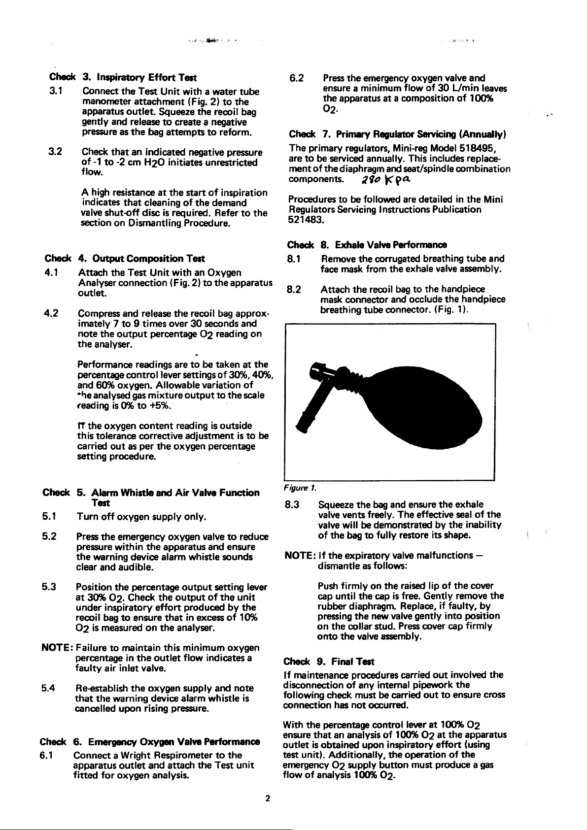
8.1
8.2
8.
Exhale
Remove
face
mask
Attach
mask
connector
the
breathing
Figure
1.
8.3
NOTE:
Squeeze
valve
vents
valve
will
of
the
bag
If
the
expiratory
dismantle
Valve
the
corrugated
from
recoil
tube
connector.
the bag
freely.
be
demonstrated
to
fully
as
follows:
Performance
breathing
the
exhale
bag
to
the
and
occlude
and
ensure
The
effective
restore
valve
malfunctions
valve
assembly.
handpiece
the
handpiece
(Fig.
1).
the
exhale
seal
by
the
its
shape.
tube
and
of
the
inability
—
5.3
NOTE:
5.4
Check
6.1
Position
at
under
recoil
O2
Faiture
percentage
faulty
Re-establish
that
cancelled
6.
Connect a Wright
apparatus
fitted
the
30%
O2.
inspiratory
bag
to
is
measured
to
maintain
air
inlet
the
warning
upon
Emergency
outlet
for
oxygen
percentage
Check
ensure
in
the
valve.
the
Oxygen
output
the
output
effort
produced
that
on
the
analyser.
this
minimum
outlet
flow
oxygen
device
rising
and
analysis.
supply
alarm
pressure.
Valve
Respirometer
attach
of
in
excess
indicates
whistle
Performance
the
setting
the
unit
by
the
of
10%
oxygen
and
note
is
to
the
Test
unit
lever
a
Push
cap
until
rubber
pressing
on
the
onto
Check
If
disconnection
following
connection
With
ensure
outlet
test
emergency
flow
9.
Final
maintenance
check
has
the
percentage
that
an
is
obtained
unit).
Additionally,
O2
of
analysis
firmly
on
the
cap
diaphragm.
the
new
collar
stud.
the
valve
Test
procedures
of
any
must
not
occurred.
control
analysis
upon
supply
100%
the
raised
is
free.
Replace,
valve
Press
assembly.
carried
interna!
be
pipework
carried
lever
of
100%
inspiratory
the
operation
button
O2.
must
lip
of
Gently
if
faulty,
gently
into
cover
cap
out
out
to
at
100%
O2
at
the
effort
of
produce a gas
the
cover
remove
by
position
firmly
involved
the
ensure
O2
apparatus
(using
the
the
the
cross
Page 3
He
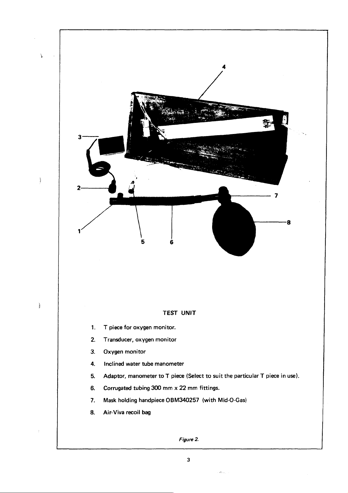
T
piece
Transducer,
Oxygen
WH
inclined
δ
Adaptor,
Corrugated
Mask
"on
Air-Viva
o
for
oxygen
monitor
water
manometer
tubing
holding
recoil
oxygen
tube
300
handpiece
bag
TEST
monitor.
monitor
manometer
to T piece
mm x 22
UNIT
{Select
OBM340257
mm
to
suit
fittings.
(with
Mid-O-Gas)
the
particular T piece
in
use).
Figure
2.
Page 4
『
it:
+
Ensure
further
the
Mid-O-Gas
use.
unit
is
re-assembled
ready
for
A.6
PROCEDURES
A
A.1
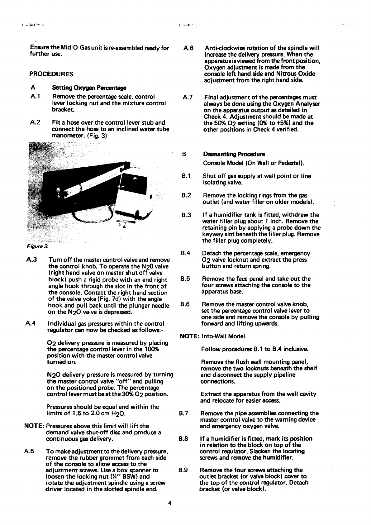
A.2
Setting
Remove
lever
bracket.
Fit a hose
connect
manometer.
Oxygen
the
locking
the
Percentage
percentage
nut
over
the
hose
(Fig.
and
the
control
to
an
3)
scale,
control
mixture
lever
inclined
control
stub
water
A.7
and
tube
B.1
B.2
B.3
Figure
3.
B.4
A.3
A.4
NOTE:
A.5
Turn
off
the
control
(right
hand
block)
angle
the
of
hook
on
Individual
regulator
O2
the
position
turned
N20
the
on
control
Pressures
limits
Pressures
demand
continuous
To
remove
of
adjustment
loosen
rotate
driver
push a rigid
hook
console.
the
valve
and
the
N20
delivery
percentage
on.
delivery
master
the
positioned
lever
of
valve
make
adjustment
the
the
console
the
the
located
the
master
knob.
valve on
through
Contact
yoke
pull
valve
gas
can
pressure
control
To
master
probe
the
the
(Fig.
back
until
is
depressed.
pressures
now
be
checked
is
control
with
the
master
pressure
control
should
1.5
above
gas
rubber
screws. Use a box
locking
adjustment
probe.
must
be
be
to
2.0
this
shut-off
delivery.
to
allow
nut
in
the
valve
at
equal
cm
limit
to
grommet
slotted
valve
operate
shut
with
slot
right
7d)
with
the
within
measured
lever
control
is
measured
‘’off’’
The
the
30%
and
H20.
will
disc
and
the
delivery
access
(%’’
BSW)
spindle
spindle
and
remove
the
N20
valve
off
valve
an
end
right
in
the
front
hand
section
the
angle
plunger
as
in
percentage
within
lift
from
to
spanner
the
control
follows:-
by
placing
the
100%
valve
by
and
pulling
O2
position.
the
produce
pressure,
each
the
needle
turning
the
side
to
and
using a screw-
end.
B.5
of
B.6
NOTE:
B.7
a
B.8
B.9
Anti-clockwise
increase
apparatus
Oxygen
console
adjustment
Final
always
on
Check
the
other
the
adjustment
left
adjustment
be
the
apparatus
4.
Adjustment
50%
O2
positions
is
from
done
Dismantling
Console
Shut
isolating
Remove
outlet
If a humidifier
water
retaining
keyway
the
Detach
O2
button
Remove
four
apparatus
Remove
set
one
forward
into-Wali
Follow
Remove
remove
and
connections.
Extract
and
Remove
master
and
If a humidifier
in
relation
control
screws
Remove
outlet
the
bracket
Model
off
gas
valve.
the
(and
water
filler
plug
pin
slot
beneath
filler
plug
the
percentage
valve
locknut
and
return
the
face
screws
the
side
attaching
base.
the
master
percentage
and
and
Model.
procedures
the
flush
the
two
disconnect
the
apparatus
relocate
for
the
pipe
control
emergency
to
regulator.
and
remove
the
four
bracket
top
of
the
(or
valve
rotation
delivery
viewed
hand
from
is
side
the
of
the
using
output
pressure.
made
and
right
the
should
setting
(0%
in
Check 4 verified.
Procedure
(On
Wall
supply
locking
at
wall
rings
filler
on
tank
is
fitted,
about 1 inch.
by
applying a probe
the
completely.
scale,
and
extract
spring.
panel
and
the
control
control
remove
lifting
the
upwards.
B.1
wall
locknuts
the
supply
to
mounting
from
easier
access.
assemblies
valve
to
the
oxygen
is
the
valve.
fitted,
block
on
mark
Slacken
the
humidifier.
screws
(or
control
valve
regulator.
attaching
block)
block).
of
the
spindle
When
the
front
from
the
Nitrous
hand
side.
percentages
Oxygen
as
to
or
from
older
filler
console
valve
console
B.4
Analyser
detailed
be
made
+5%)
and
Pedestal).
point
or
the
models).
withdraw
Remove
down
plug.
emergency
the
press
take
out
to
valve
knob,
lever
by
inclusive.
panel,
beneath
the
pipeline
the
wall
connecting
warning
its
position
top
of
the
the
locating
the
cover
Detach
will
the
position,
Oxide
must
in
at
the
line
gas
the
the
the
Remove
the
the
to
pulling
shelf
cavity
the
device
to
Page 5

-B.10
Remove
taking
adjusting
on
a
corresponding
ator
position
the
the
body.
same
and
care
shim(s).
side
and
position
inspect
not
of
the
This
the
the
to
damage
Note
the
mixture
mark
on
indicates
disc
must
during
sealing
or
misplace
‘’O’
scribed
control
the
control
the
resetting
be
replaced
assembly.
ring
the
mark
plate
regul-
in
and
set
between a straight
diaphragm
body
point
Adjustment
housing
“A”.
and
the
on
the
allows
(Ref.
bearing
regulator
seat
of
B14).
lever
the
the
edge
face
of
stirrup
arm.
control
setting
across
the
dual
loading
regulator
of
dimension
the
regulator
seat
B.11
B.12
NOTE:
B.13
B.14
If
the
demand
should
cloth
Remove
bonnet
control
by
block.
signs
Care
sealing
or
instrument.
Remove
lever
and
new
Access
requires
unscrewing
disconnection
control
must
spacer
housing
See
mentioned
be
cleaned
and
Methylated
the
and
detach
spring.
sliding
prise
it
Inspect
of
perishing.
must
be
faces
the
bonnet
the
pin
to
the
pin.
Remove
assemblies
to
the
removal
the
valve.
be
loosened
detached
unscrewed
Figure 6 for
items.
valve
shut-off
and
Spirits.
screws
upwards
on
screws
around
the
bonnet
The
diaphragm
towards
the
diaphragm
taken
to
avoid
each
bonnet.
free
attaching
body
and
the
seat
as
required.
control
of
The
regulator
of
the
holding
all
tubing
seat
housing
and
removed,
and
the
and
identification
disc
polished
with a soft
each
regulator
and
is
removed
the
for
damaging
Do
not
with a sharp
the
seat
extract
assembly,
seat
base
plate
locknuts
to
and
the
locknuts
the
regulator
removed.
of
above-
is
dirty
it
diaphragm
control
damage
the
by
master
seat
or
the
lever
lever
replace
assembly
inlet
NOTE:
C.3
it
is
recommended
setting
procedure.
the
diaphragm
stirrup,
It
is
recommended
diaphragm
tool
retainer
diaphragm).
is
located
when
regulator
Before
ensure
common
opposite
The
the
face
the
in
the
bonnet
body.
positioning
the
regulator
extended
peripheral
diaphragm
threaded
prior
to
bonnet
that a suitable
be
made
is
replaced
assembly
diaphragm
It
is
essential
an
even,
is
the
centre
holes
holes
in
attaching
retaining
to
aid
this
that,
when
by a complete
(including
that
unstressed
screwed
diaphragm
stirrup
line
diaphragm
must
neatly
the
regulator
the
bonnet.
screws
dimension
measurement
necessary,
regulator
plate
and
the
diaphragm
condition
to
the
dual
assembly
aligns
with
between
holes.
lie
body
Tighten
evenly.
the
two
(Fig.
over
4)
B.15
C.1
0.2
For
assembly
air
inlet
and
master
relevant
Re-Assembly
The
apparatus
order
of
cleanliness
and a re-inspection
should
The
following
attention.
Before
seat
lever
pin
is
sitting
When
re-positioning
seat
housing
dimension
drawing,
seat
lever
held
firmly
a
dimension
detail
apparatus,
shut
off
diagrams
Procedure
is
the
Dismantling
of
all
be
carried
details
tightening
pin
to
the
within
and
nominated
(Fig.
6)
pin
installed
bearing
of
18
emergency
attached.
re-assembled
components
of
out.
the
seat
must
on
mm
on
the
valve,
all
require
screws
body
its
groove
the
control
lever
“А”
be
and
the
(0.71
warning
oxygen
refer
to
the
(Figure
in
the
Procedure.
is
essential
items
for
damage
particular
holding
ensure
in
the
critical
on
sectional
that
the
regulator
achieved.
the
seat
seat
assembly
inches)
device/
valve
7).
reverse
The
the
the
body.
With
lever
is
C4
C.5
Figure
4.
if
the
mixture
eguivalent
regulator
carefully
operation
“O”
ring
may
be
required
Replace
Ensure
control
body
percentage
the
scale
are
54%
when
“’O’’
that
plate
O2
Warning:
marks
and
are
pre-set
of
the
mixture
be
conducted
mination
control
bearing
body
is
until
flat.
an
additional
in
the
top
ring
the
setting
and
aligned
control
position
the
setting
The
above
the
percentage
during
control
without
that
the
plate
face
on
the
worn
or
scratched,
Following
shim
of
the
control
to
obtain a good
if
worn
or
marks
the
control
during
lever
on
marks
assembly,
must
the
mentioned
scale
manufacture.
disc
only
accurate
control
apertures
seat
or
the
control
lap
the
lapping
beneath
the
disc
seal.
damaged.
on
the
mixture
regulator
The
be
indicating
percentage
are
aligned.
setting
location
Replacement
must
not
deter-
are
Page 6

equal
and
the
54%
in
the
when
percentage
O2.
This
field
the
setting
control
operation
situation.
marks
lever
is
not
are
aligned
indicates
recommended
Bee
C.6
Conduct
Bubble
apparatus
conditions
test
Checks
all
under
after
2,
3,
and 4 after
sealing
joints
full
supply
re-assembly.
re-assembly.
on
the
pressure
Figure
5.
.
Item
1
2
3
4
5
6
7
8
9
10
11
12
13
14
15
16
17
ITEMS
Part
No.
M1110
OBM340257
NB705
OBM372748
NB559
DM427
OR27A1
DM435
OR9A2
DM423
DM421
OR12A2
DM431
DM432
DM430
DM429
NB538
REPLACEABLE
PARTS
UNDER
Description
Facemask,
Handpiece,
Grommet,
Corrugated
Knob,
Shim,
"O"
Disc,
“O”
Seat
Housing,
“O”
Diaphragm
Lever,
Plate,
Stirrup,
Retainer,
anti-static
mask
%’’
tube,
master
control
ring
shut-off,
ring
assembly
seat
ring
seat
diaphragm
regulator
%’’
LIST
MAINTENANCE
holding
dia.
hole
one
metre,
shut-off
adjusting
demand
dia.
valve
valve
SERVICE
anti-static
Qty.
1
1
2
1
1
As
Required
1
1
2
2
2
2
2
2
2
2
2
Page 7

Fig. 6 Control
Regulator
and
Mixture
Control
6
/
;
SET
11)
POSITION
TO
OBTAIN
}
ーー-
Mixture
Control
Plate
17
16
OF
18
SEAT
mm
HERE.
ジス
o
HOUSING
ンジ
IN
M
“J
x
22
ラン
クン
の
の
A
Pi
|
'
|
-
+]
K
SS
Ñ
Ny
N
N
M s
40
N
Rİ
BN
AN
N
TON
让
4
プ
GIA,
NS
3
Г,
x
NS
>
レーン
NY
SN
クン
|
I
iF
ンク
|
TT
4
=>
7
8
7
15
14
13
518495
(301112)
|
P
4
+
—
-|
=
_
-
/
A
SY
0
à
NTFS
の
NS
NN
Si # No
NS
“
,
TR
GA
レン
、
IEA
。
VANS
ノン
~
7
~,
4
~
12
11
i
10
A
>
KN
k
A
DN
、
、
ヽ
XS
AN
、
M
AROSA
I
a
A.
s
s
N
N
>
n
、
S
BO
E
AFFATTO
S
a
>
>
、
x y i
è
M
Ba
KESK
7.
+
,
レ ェ ン
ング
^
NAAN
シン
+
i
ン
2
i
LR
ン
ルン
ØS
,
N
7
D
(Holding
J
B
(Inlet
(Seat
(Seat
.
housing
housing-adjusting
locknut
spacer)
locknut)
not
shown)
nut)
Page 8

1
TO
ALARM
TO
MACHINE
OUTLET
WHISTLE
>
AIR INLET
VALVE
:
4
>
2
(D7
Figure
7
E)
INLET
ο,
ΙΝΙΕΤ
-----
(Α)
(D) i
8
J
>
İp
9)
VA
- 3 long.
/
(10
4
Note:
(item
Jİ
AJ
13
and
spindle with
0.2
mm
with
and
seat
Cut
to
9)
Assemble
14
clearance
spindle
shut,
spring
17
on
central
0.1
fully
mm
items
to
out
Item
1
2
3
4
5
6
7
8
9
10
11
12
13
14
15
16
CIG
ププ
プア
ШЕЕ}
ノン
The
(Incorporated
Nedishieid
Macquarie
—
11-17
Part
No.
DM468
M537
M543
DM474
NB1284
OR1A2
7968003
AT45
NS9
NS37
DM464
OR1A2
DM453
DM454
NB493
DM462
Commonwealth
Khartoum
South
New
in
Division
Technology
Industrial
Wales)
Road,
North
Description
Washer
Filter
Collar
Gases
Centre
Ryde,
Diaphragm
safety
Cap,
safety
Disc,
Neoprene
ring
“O”
Valve,
Spring,
Seat
Screw,
“O”
Washer,
Screw,
Yoke
Schrader
air
(complete)
gland
ring
P.T.F.E.
socket,
Limited
N.S.W.
2113.
8
valve
valve
washer
valve
3/16"
BSW
x
3/16”
Lg.
Oty.
2
1
1
1
1
1
1
2
2
2
2
2
1
1
1
1
Publication
1,
ssue
521467
January
AP/500/181
1981
Page 9

AdO9
NOILVOISILNSQI
Siva
ャ
6/
|
TESTİ
80
SWIVIHAVIC
1V3S
688218
ΟΙΛΞ3Α
IN3W39V
ININGVM
Iddd
SVI-O-GIW
30
SQOUVMOI
NIVIHAVIO
30IS
HLOONS
098213
JI
TIOHINOO
YITIOH
MAN
0315
YSONNId
688313
SOJVMOL
WNIVIHAVIO
30IS
HLOOWS
ONV
(688316)
ON
|140009
vd
|
"(098C1S)
(898015)
NOTIVTIVISNI
8600464
831114
3ZNO88
{
8928213
ἀνο
MAN
ーーー
1
ヨ
TNr
|
“0
HA
AVI
WNIVIHAVIO
80*0/60*0
(658618)
40
39VH4
JO
и043
NIVIHAVIA
3ATI9
SSINADFHL
NOI1V9131.1N301
|
dais
IVIZILVW
Ol
SALON
A
1SM3SSV
CIYINDIY
SYNSVSW
IAOWIU
31
/1
OL
HSYNDS
JI0I0H
403
3YNOJIOJA
ヨ
AGBV
1Y
コ
ヨコ
d
ヨ d
AP?»
/
ㅇ
Page 10

COMWELD
MEDICAL
GROUP
PRODUCTS
Neg
em
Kit
ee
AAA
ие
INSTALLATION
I.
DESCRIPTION
Kit
TMIH
It
contains
in
fittings,
2~
GENERAL
2.1
Norgren
Norgren
and
then
2.2
Diameter
To
prevent
the
Oxygen
Nitrous
2.3
Snap
Gauge
Both
check
2.4
Thread
sealants.
For
general
For
prevent
INSTRUCTIONS - KIT
Pt.No.512467
and
INFORMATION
Regulators.
regulators
the
regulator
installing
Coding
Oxide
Testing.
Norgren
the
outlet
the
1/8
the
is a replacement
TM114.
Norgren
and a number
gas
connections
use,
BSP
fitting
regulators,
have 1 inlet
seat
ensure
of
Tubing.
cross
connections.
regulators
pressure.
Loctite
regulator
from
Pt.No.
which
of
special
port
is
visible
through
that
the
supply
connection,
and
have a connection
S20
turning
the
This
Pipe
to
snap
the
5/16
fitting
Sealant
gauge
when a snap
512467
primary
adaptors.
regulator
have
been
and 3 outlet
the port.
gas
is
connected
1/4
inch.
diameter
inch.
diameter
to
which a snap
is
normally
is
recommended.
fitting-Loctite
gauge
kit
cleaned
ports,
The
to
tubing
tubing
sealed
with a blind
271
is
attached.
for the
for
medical
inlet
the
port
and
and
gauge
or
Loctite
Mid-O-Gas
use,
port
ts
marked
marked
with
fittings
fittings
must
may
be
nipple.
277
apparatus
nylon
tubing,
with
the
arrow.
must
be
be
used
fitted
to
set
is
recommended
an
used
for
TM36,
push
arrow
for
the
and
to
3.
CONTENTS
{tem
Part
1
2
3
4
5
6
7
8
9
10
11
12
13
Number
K50
512258
512434
512443
512454
512455
512456
512460
512464
512465
512466
7966030
521982
Description
Nut
1/4ins.BSP
Regulator
Elbow
Swvl
Elbow
Swvl
Adaptor
Nipple
Elbow
Elbow
Adaptor
Tube
Tube
Circlip
Instructions
Regulator
Blank
Swvl
Swvl 1 1/4BSPT-5/16tube
ON/OFF
1/4
OD
5/16
Bowed
Norgren
OD
0-350Kp
1/8BSPT-1/4tube
1/4BSPT-1/4tube
1/8BSPT-5/16tube
control
Ext.22.2
mm
to
Quantity
elbow
ο
ved
2
2
4
2
2
2
ΕΕ
Net
EN
ΤΕ
님 | 는
dl
Lara
ken
Åen
o!
i
Page 11

4.
PROCEDURE
Notes:-
the
Mid-O-Gas
It
is
important
with
the
Part
No.
1.
Remove
2.
Remove
3.
Disconnect
emergency
4.
Tum
remove
5.
Taking
the
inlets
comers
may
6.
Fit
Elbow
other
.
Fit
Adaptor
Looking
on
regulator,
9.
Fit
the
connected
service.(see
the
swivel
IO.
Fit
Adaptor
Bend
11.
Fit
Adaptor
This
kit
should
apparatus.
that
servicing
521467
the
outer
the
pipes
the
oxygen.
the
unit
over
the
base
care
not
to
the
of
the
be
more
room
item 3 to
Norgren
item 5 to
at
the
then
regulators
for
Oxygen
Note
inlets
item 9 to
the
Adaptor
item 9 to
be
installed
this
procedure
procedures
detailed
case.
connecting
02
and
N20
and
undo
bracket.
to
move
the
secondary
base
regulator.(see
base
place
to
2.2).
to
bracket
if
the
the
inlet
the
opposite
of
the
another
the
main
service and
Position
the
secondary
regulators
when
02
regulator,
Elbow
to
clear
the
Elbow
by a person
is
carried
in
Servicing
the
inlet
pipes
at
the
the
nuts
that
secondary
and
refitted.
inlet
is
positioned
of
one
of
Note
2.1.)
ports
blank
adaptor
item 5 in
assembly:
the
the
regulators
regulators.
item 4 ¿hen
bonnet
of
item 8 then
trained
out
in
block
to
air
valve
secure
regulator
swivel
Refit
the
Norgren
of
both
off
the
making
regulator
to
connect
the
N20
connect
in
the
servicing
conjunction
Instructions,
the
primary
and
the
pull
main
regulators
off
assembly
:
seat
housings,
the
inlets
so
the
base
bracket.
towards
the
front
regulators
regulators.
port
next
clockwise
the
remaining
sure
that
the
with
the
5/16ins.
clear
the
outer
this
assembly
secondary
this
regulator
assembly
of
then
the
PVC
to
the
Slightly
that
they
point
Note:-
comer
and
Elbow
from
port,
of
both
regulator
with
is
connected
case , then
to
the
02
to
the
N20
remove
tube
that
base
bracket,
loosen
towards
In
some
of the
base
item 7 to
the
regulators.
the
for
tighten
outlet
of
outlet
the
regulators.
supplies
the
then
both
locknuts
the
rear
assemblies,
bracket.
the
inlet
inlet
of
the
1/4
ins.
fitting
Nitrous
both
lock
the
inlet
of
the
inlet
-
on
there
of
the
is
Oxide
nuts
block.
block.
on
12.
Using
regulators.
and
the
Fittings
a)
Ensure
b)
Simply
c)
To
dismantle,
13.
Reconnect,
PVC
tubing.
14.
Remove
“A".
If
15.
Fit a snap
At
280kPayLock
16.
Repeat
17.
Complete
Instructions.
Part
No.
521982
the
Nylon
Run
and
adjustment
is:
that
the
end
push
the
simply
the
02
the
secondary
necessary,
gauge
with
the
procedure
the
assembly
Issue
02
Date
198
tubing,
cut
1/4ins.
the
screws
of
the
nylon
tube
into
push
and
N20
regulator
reposition
to
the
02
Norgren
Clip item
using
of
Nylon
of
the
the
collet
the
tube
pipes
the
12.
nitrous
the
Mid-O-Gas
for
02
and
tubing
secondary
tube
is
properly
until
into
the
to
the
air
bonnets
seat
and
housing.
regulator,
Replace
oxide
5/16ins.
so
that
the
regulators.
sguared
it
locates
through
fitting,
hold
valve
and
diaphragms,
(refer
pressurise
the
snap
gauge
for
the
N20
and
check
for
N20,
connect
tubing
is
The
method
off.
the
down
reconnect
in
turn,
to
the
Mid-O-Gas
with
oxygen,
with
Norgren
it's
calibration,
the
not
strained,
of
assembly
'O'
ring.
the
collet
the
emergency
to
check
Servicing
and
Nipple
item
regulator.
in
accordance
inlet
is
then
and
the
set
6.and
block
to
clear
of
the
of
Push
pull
back.
withdraw
oxygen
critical
Instructions)
the
regulator
Nut
item
with
the
Norgren
outer
case
In
Tube
the
tube.
supply
dimension
to
the
Service
 Loading...