

Page 1
CIDRON
Installation guide
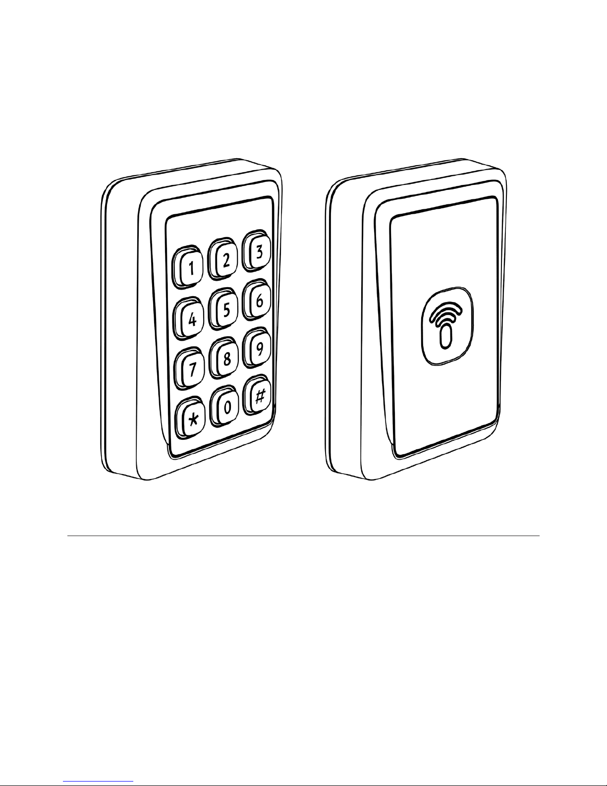
Cidron Standard Reader
Cidron Combi Reader
Page 2

2
Cidron Standard Reader Technical specifications
Operating frequency 13,56MHz.
Reading technologies
MIFARE CSN 4 byte, MIFARE CSN 7 byte, MIFARE Classic, MIFARE Plus,
MIFARE DESFire 0.6 and MIFARE DESFire EV1.
Also supports other ISO 14443 A/B* compatible cards.
*Not all ISO14443 B cards have been implemented in the reader, please contact
Nexus for more details on current status. MIFARE is a registered trademark of
NXP B.V. and is used under license.
Secure Access Module
(SAM):
MIFARE SAM AV2, external SIM card
connection slot.
Communication
protocols
Wiegand, Clock/Data, OSDP 1, OSDP 2 (including Secure channel),
RS232 and RS485.
Reading output format 24-1024 (excluding parity bits)
Keypad output format
Wiegand 4bit, Wiegand 8bit (Dorado), Wiegand 26bit, OSDP ASCII format.
Keypad
12 digit keypad in 4 rows of 3 keys in each row with configurable
backlight in blue color. Control features On/Off/Auto indicators.
Light itensity can be adjusted.
Indicators LED, Green, Red and Yellow (Bi-color). Backlight in blue color. Buzzer.
Power supply 9 – 30VDC
Current consumption
24VDC idle mode with heater inactive 40 mA**
12VDC, idle mode with heater inactive 50 mA**
**Current consumption differs depending on functionality used
and can also be limited in the reader configuration.
Input/Output
4 input for LED and buzzer and 2 configurable
input/output.
Tamper alarm
Built-in mechanical tamperswitch which allows for
indication both break off protection and opening of the reader.
Operating temperature
–40° – +70°C
When installing readers in environments with extreme heat
(above + 50*C) it is recommended to utilize the climate protection
SC9901-V which provides additional shading to the reader.
Heater Thermostat controlled embedded heater.
Operating humidity
0 – 95% RHNC
(Relative Humidity No Condensation)
Ingress Protection
Classification
IP 65
Housing dimension
L=109mm, H=25mm, W=79mm
Configuration Methods Configuration card, reader tool software or factory configured readers.
Page 3

3
Operating frequency 125kHz & 13,56MHz.
Reading technologies
Electromarine EM4200, HID® Proximity, MIFARE CSN 4 byte,
MIFARE CSN 7 byte, MIFARE Classic, MIFARE Plus, MIFARE DESFire 0.6 and
MIFARE DESFire EV1. Also supports other ISO 14443 A/B* compatible cards.
*Not all ISO14443 B cards have been implemented in the reader, please contact
Nexus for more details on current status. MIFARE is a registered trademark of NXP
B.V. and is used under license.
Secure Access Module
(SAM):
MIFARE SAM AV2, external SIM card
connection slot.
Communication
protocols
Wiegand, Clock/Data, OSDP 1, OSDP 2 (including Secure channel),
RS232 and RS485.
Reading output format 24-1024 (excluding parity bits)
Keypad output format
Wiegand 4bit, Wiegand 8bit (Dorado), Wiegand 26bit, OSDP ASCII format.
Keypad
12 digit keypad in 4 rows of 3 keys in each row with configurable
backlight in blue color. Control features On/Off/Auto indicators.
Light itensity can be adjusted.
Indicators LED, Green, Red and Yellow (Bi-color). Backlight in blue color. Buzzer.
Power supply 9 – 30VDC
Current consumption
24VDC idle mode with heater inactive 60 mA**
12VDC, idle mode with heater inactive 90 mA**
**Current consumption differs depending on functionality used
and can also be limited in the reader configuration.
Input/Output
4 input for LED and buzzer and 2 configurable
input/output.
Tamper alarm
Built-in mechanical tamperswitch which allows for
indication both break off protection and opening of the reader.
Operating temperature
–40° – +70°C
When installing readers in environments with extreme heat
(above + 50*C) it is recommended to utilize the climate protection
SC9901-V which provides additional shading to the reader.
Heater Thermostat controlled embedded heater.
Operating humidity
0 – 95% RHNC
(Relative Humidity No Condensation)
Ingress Protection
Classification
IP 65
Housing dimension
L=109mm, H=25mm, W=79mm
Configuration Methods Configuration card, reader tool software or factory configured readers.
Cidron Combi Reader -
Technical specifications
Page 4
4
1 x
2 x 2 x 2 x 1 x
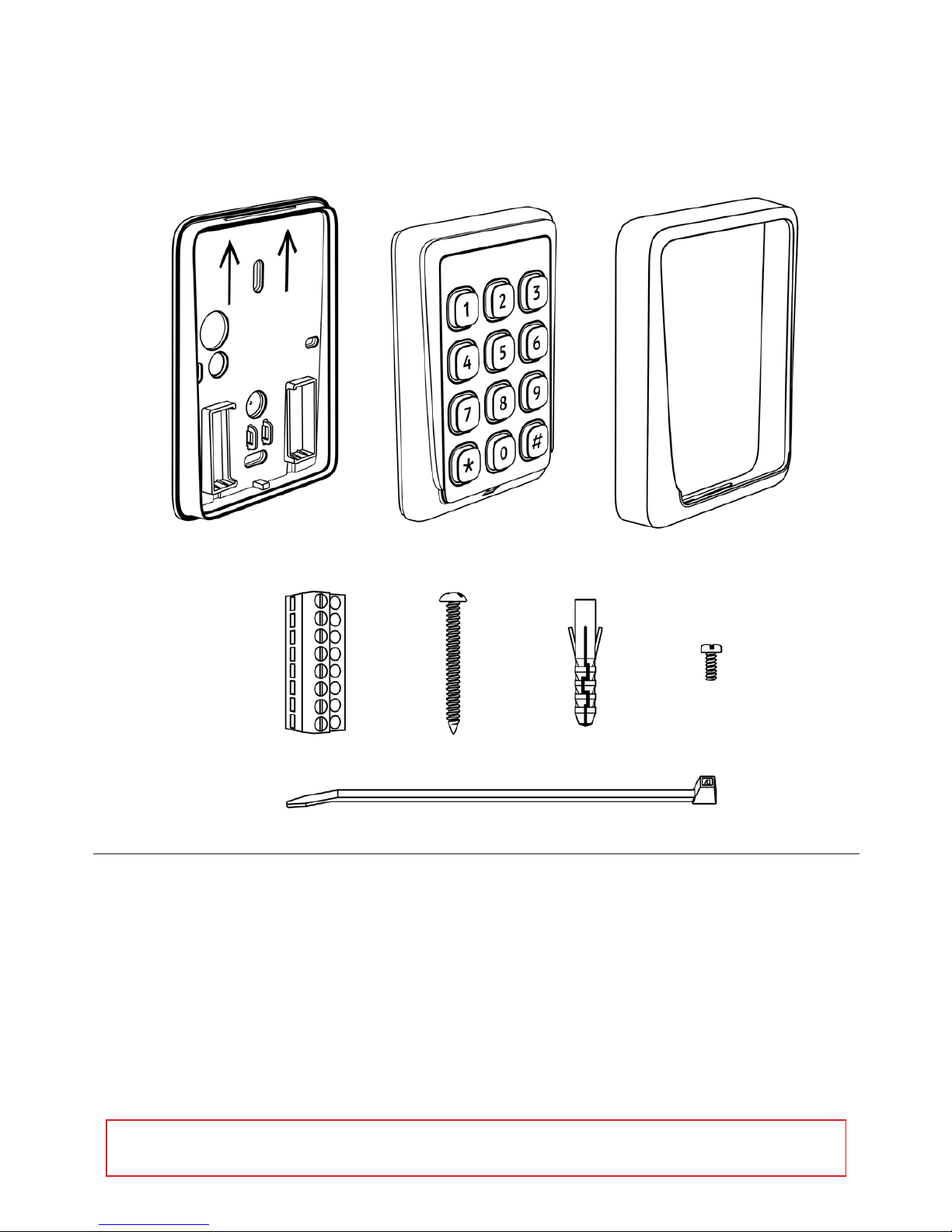
• 1pc Installation plate
• 1pc Reader module with front plate
• 1pc Front cover
• 2pcs Terminal connector (8-pin)
• 2pcs Installation screws
• 2pcs Screw plugs
• 1pc Cable strip
• 1pc Fixing screw
• 1pc Quick installation guide
Package content:
* Please note that all pictures in this manual are illustrations and do not represent the actual sizes and form of
the components.
Page 5
5
~20 cm
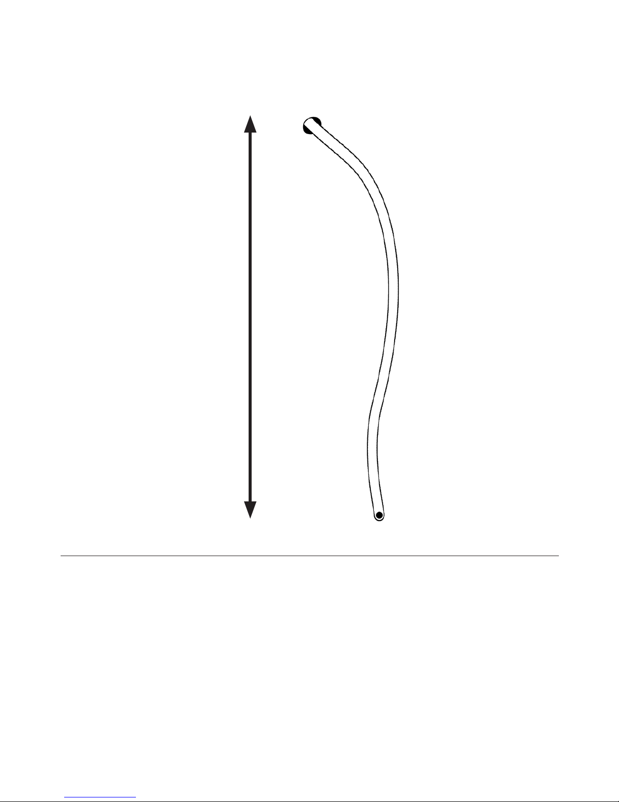
In order to facilitate installation a cable length of 20cm
is recommended.
Page 6
6
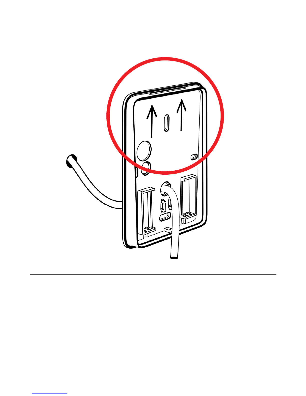
Ensure that the installation plate is fixed in the correct direction,
i.e. the arrows pointing upwards.
Page 7
7
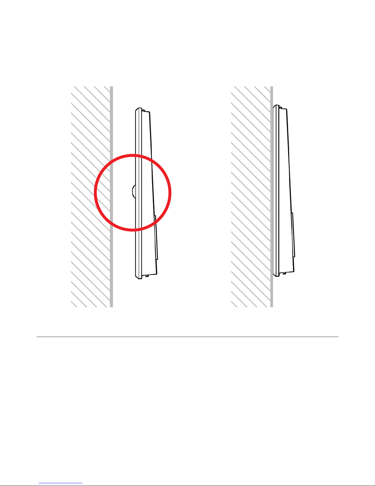
Ensure that the area behind the tamper switch bulb of the installation
plate is flat, to be able to push the bulb for correct tamper alarm
functionality. If it is not flat enough, you will find accessories in this
manual that will assist with improving this functionality.
Page 8
8
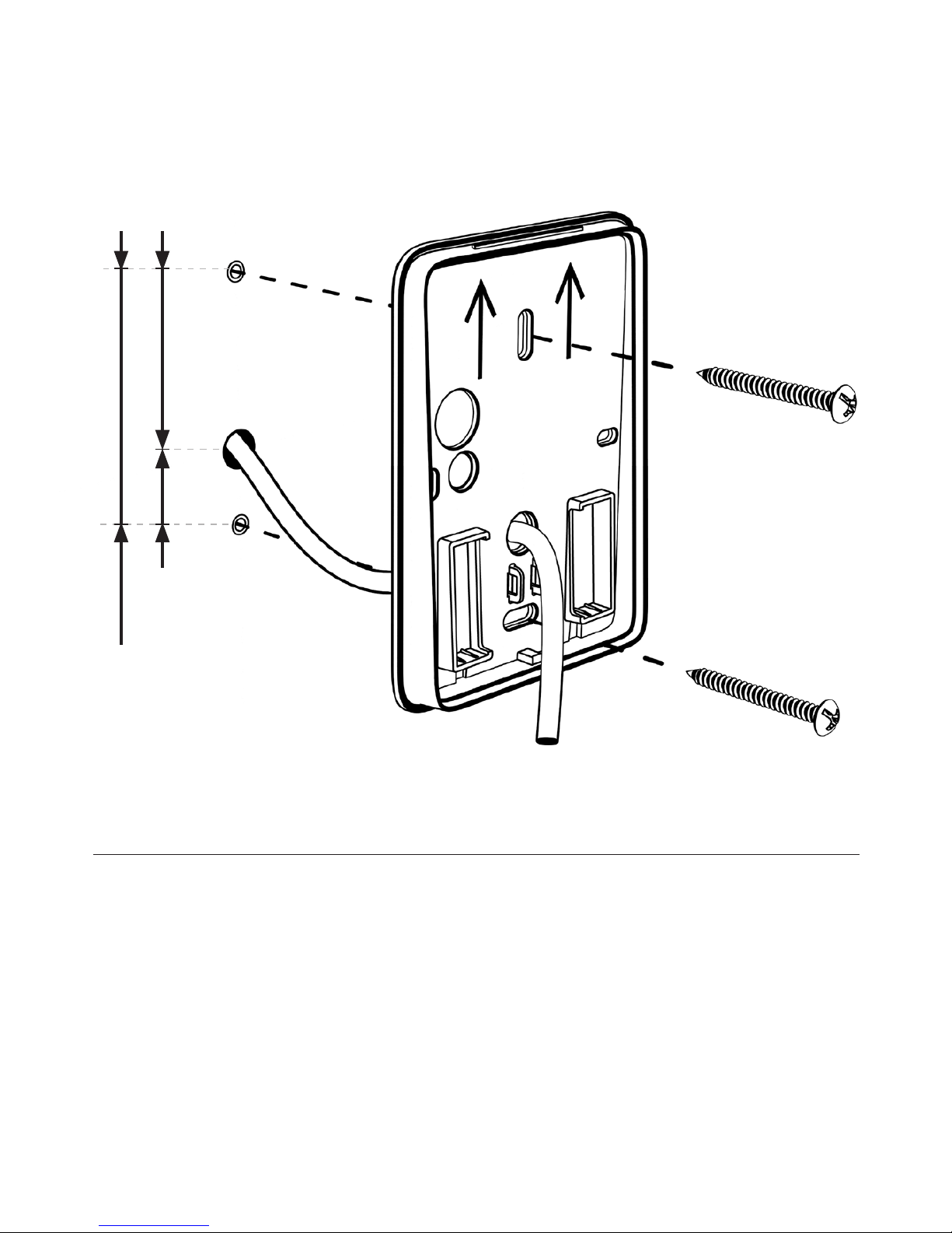
When installing directly to wall or door, use the recommended
vertically aligned holes (as picture describes). If using other screws
than the ones supplied with the reader, make sure to use a flat headed
screw with a maximum height of 2.8 mm and a maximum diameter of
7.8 mm on the screw head.
Make sure not to tighten the screws too hard as doing so will deform
and skew the installation plate. This may affect the tamper switch
functionality of the reader. Countersunk screws should never be used.
21 mm
48 mm
69 mm
Page 9
9
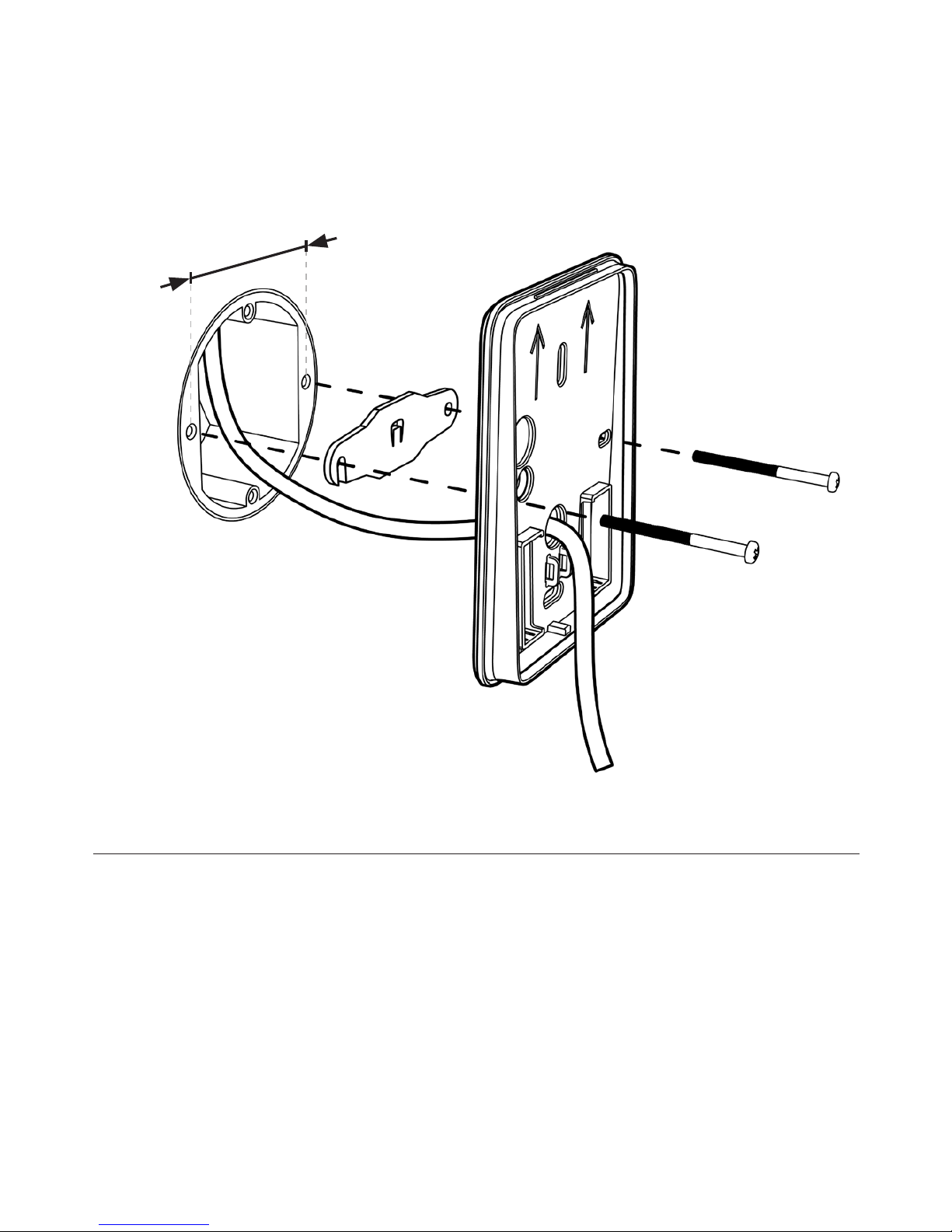
When installing reader on a installation box, use the recommended
horizontally aligned holes (as picture describes). If the tamperswitch
functionality should be used a installation box tamperswitch bracket
must be installed between the reader and the installation box.
Utilize screws supplied with the installation box but make sure to use a
screw and possible also washer with a maximum height of 2.8 mm and
a maximum diameter of 7.8 mm.
Installation box tamperswitch
bracket, part no: SC9189-RF
60 mm
Page 10
10
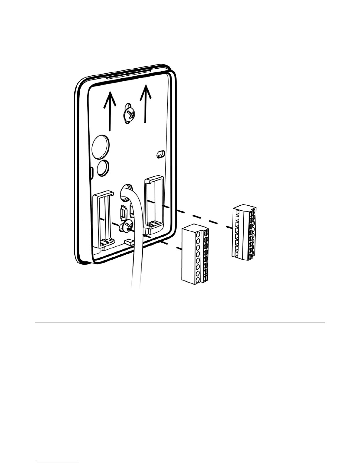
P1 - Blue socket
P2 - Black socket
Make sure to place the terminal connectors with the fastening
screws facing towards you.
Page 11
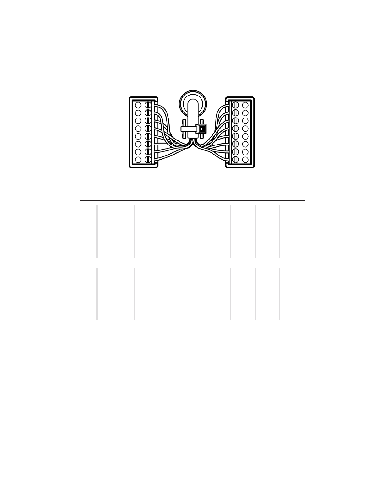
11
Tamper
GPO1
GPO2
GND
B/RX
A/TX
GND
DC+
CP
D1 Clock
D0 Data
GND
G-LED
R-LED
BZ CTRL
K-LED
P1
Blue
P2
Black
Tamper
GPO1
GPO2
GND
B/RX
A/TX
GND
DC+
CP
D1 Clock
D0 Data
GND
G-LED
R-LED
BZ CTRL
K-LED
Tamper output
General purpose I/O
General purpose I/O
Ground
RS485 RS485 +
Power supply
Power supply 9-30 VDC
Card Present
Wiegand Data1/Clock/Data, ABA2
Wiegand Data2/Clock/Data, ABA2
Ground
External Green LED control
External Red LED control
External Buzzer control
External Keypad LED control
DescriptionPIN Wiegand
x
-
x
-
x
x
x
x
x
x
x
x
x
P1 - BlueP2 - Black
RS485/
OSDP
Clock/
Data
-
-
x
x
x
x
x
-
-
x
-
-
-
-
-
-
x
-
x
x
x
x
x
x
x
x
x
x
Notes:
1. Maximum wiegand cable length is 150 meters and requires a high
quality shielded cable with minimum AWG18 dimension (=0.8231mm2)
in an environment free from electrical noise.
2. Wiegand requires dedicated wires for external control of green LED,
red LED, buzzer and keypad backlight LED.
3. When utilizing the GPI/O’s, each respective GPO1 or GPO2 must
be connected to each respective pin and also to GND. The general
purpose input/output will only be activated if so applied in the reader
configuration.
4. RS485/OSDP requires twisted pair cable.
Page 12
12
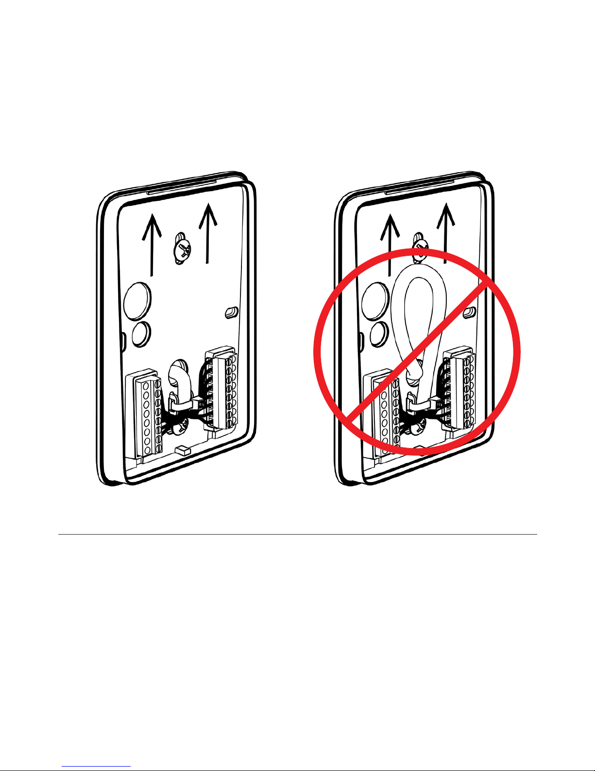
Make sure no excess connection cable is left in between the reader
module and the installation plate.
Use the enclosed cable strip to fix the cable in the cord grip. It is
recommended to connect the the wires to the terminal connectors
before tightening the cable strip.
Page 13
13
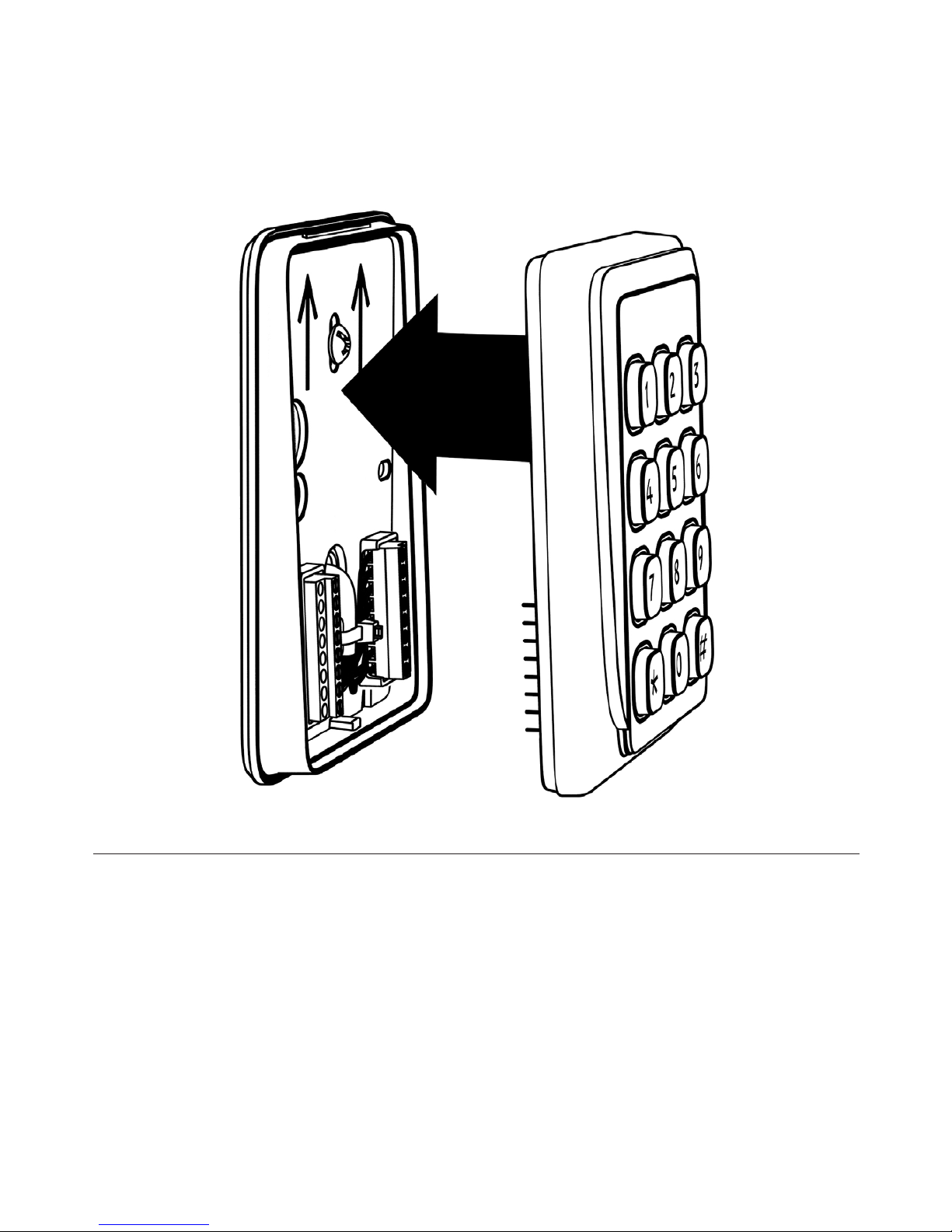
When installing the reader to the mounting plate ensure that
the reader pin header contact perfectly aligns with the terminal
connector block.
Page 14
14
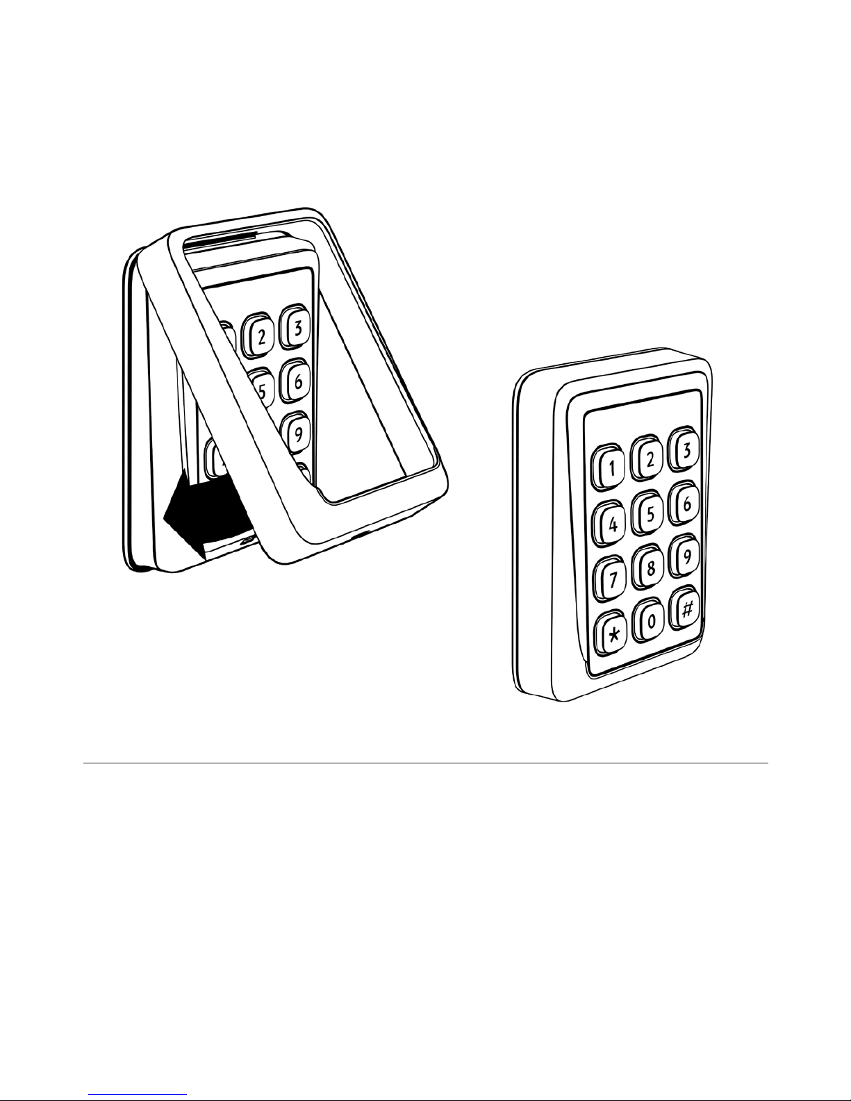
Mount the front cover as per the image above and make sure it
is fitted correctly.
In order to do so, allign and fit the top snap fastening, apply and
maintain pressure on the top of the front cover while sliding the
front cover over the bottom snap fastening.
Page 15
15
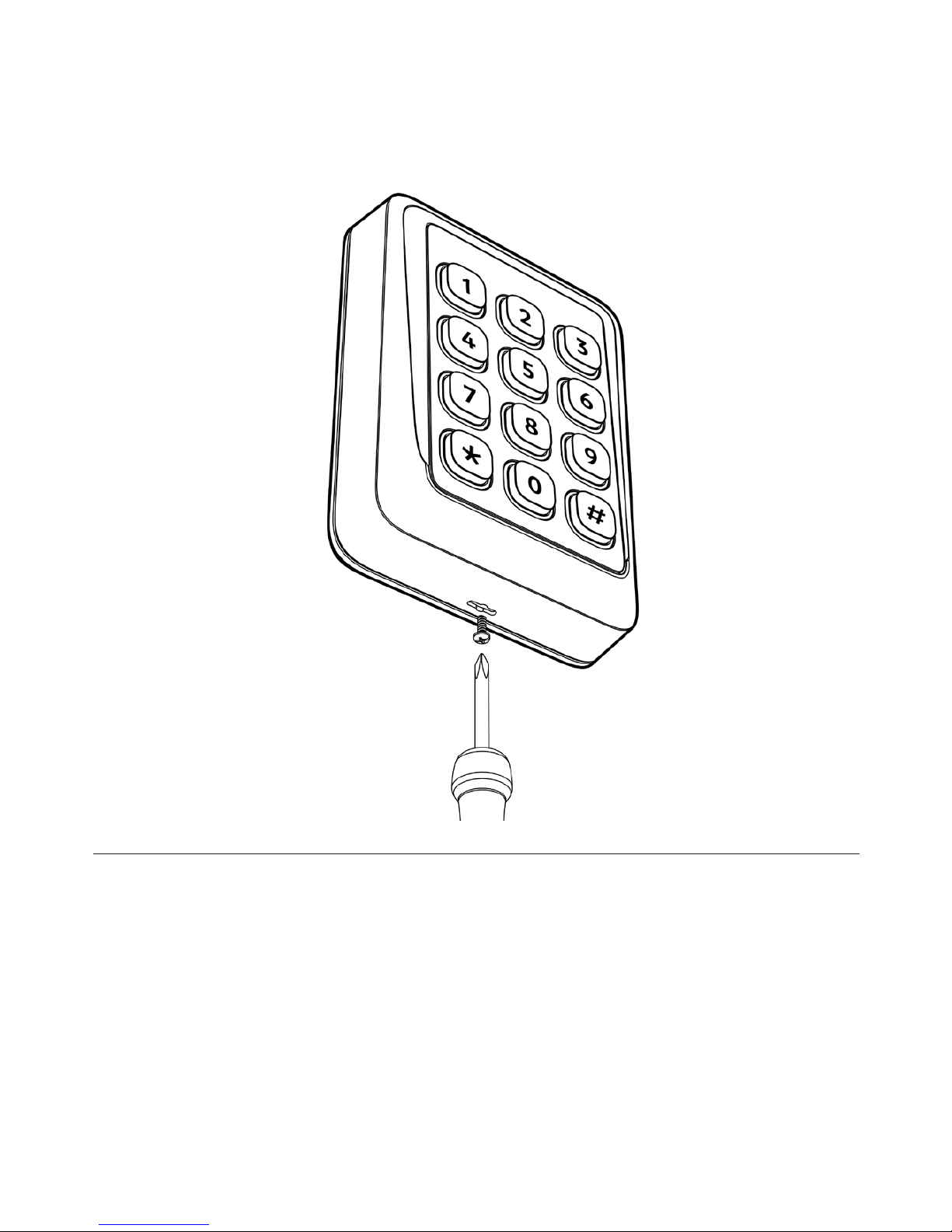
To secure the front cover to the reader use the supplied
fixing screw and fix it into the installation plate through the
front cover.
Page 16
16
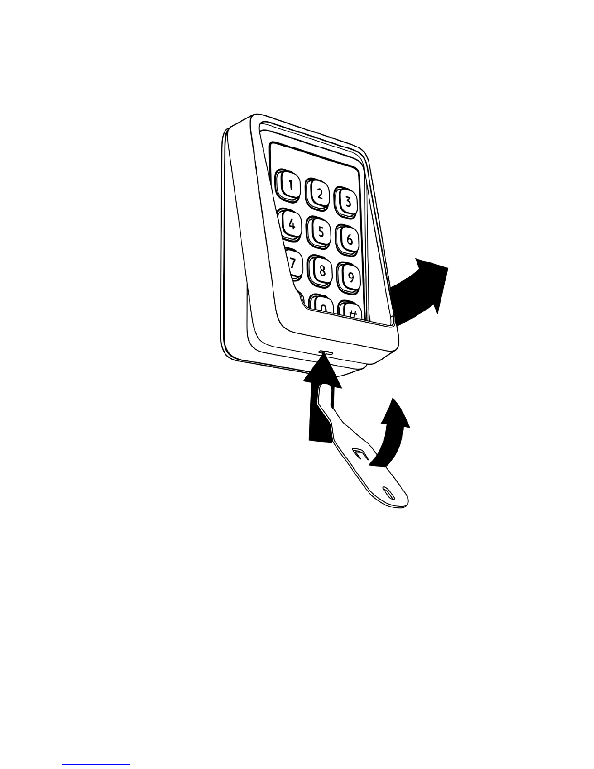
To open the reader, first remove the fixing screw and
then detach the front cover from the installation plate by
inserting the tip of the tool into slot at the bottom of the
front cover and move the tool upwards. This will release the
front cover without damaging the front cover and/or the
installation plate.
Cidron tool, part no: SC9914
Page 17
17
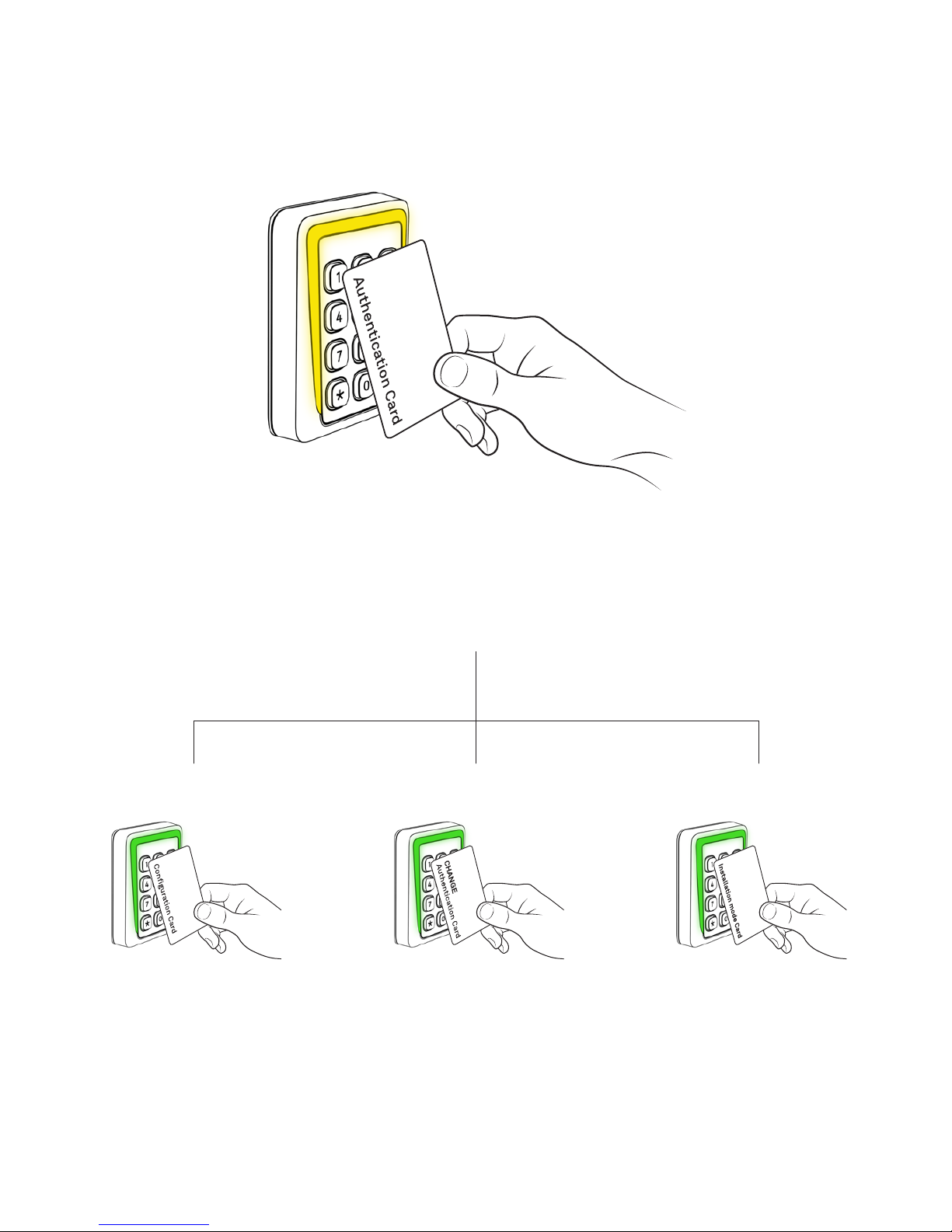
Overview, programming of reader
Resetting the
OSDP secure
channel.
see page:
21
Changing
authentication card
see page:
20
Setting the reader in programming mode
see page:
18
Configuring the
reader
see page:
19
Page 18
18
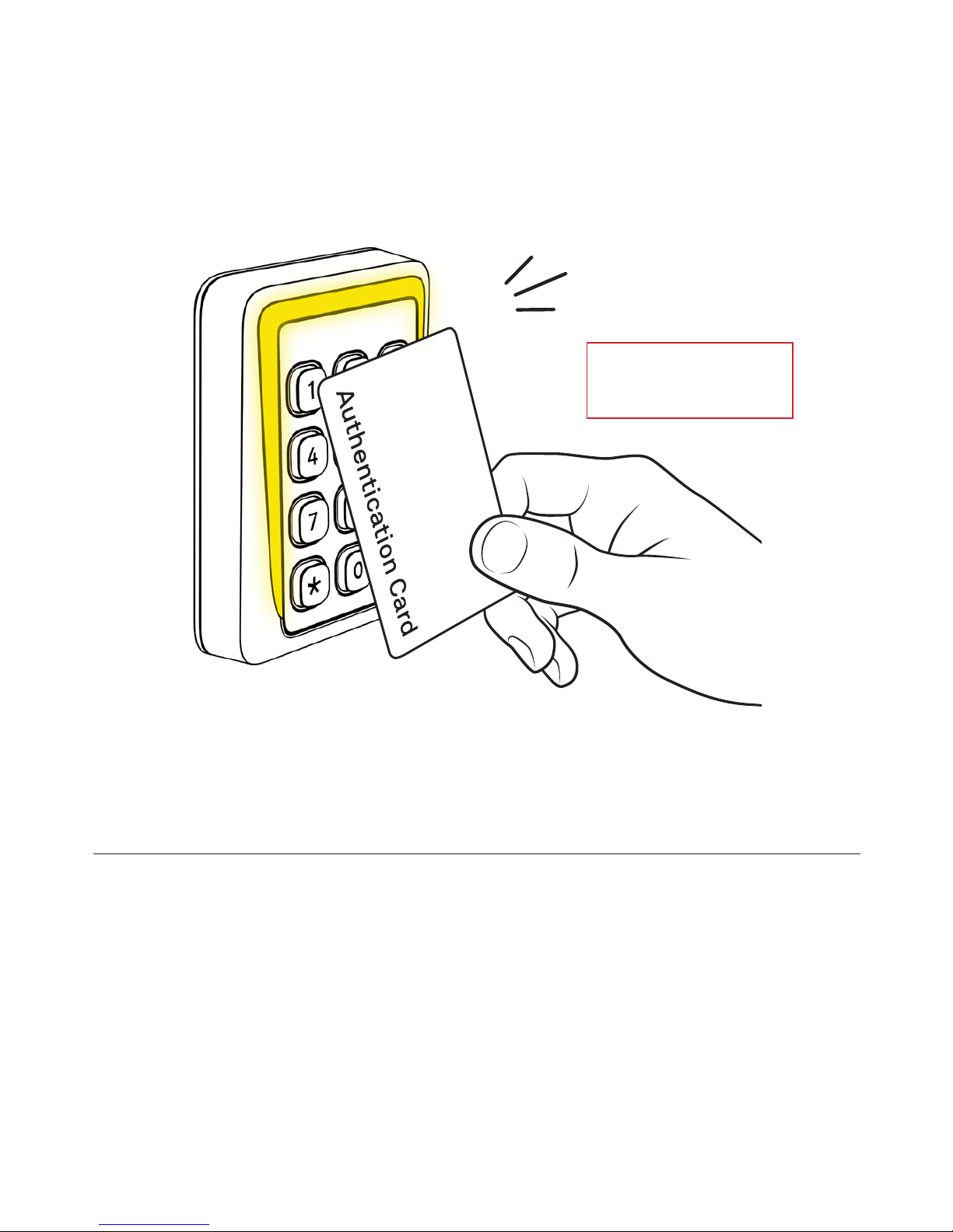
In order to set the reader in programming mode, present the valid
“Authentication Card” to the reader as shown. The reader will beep
and start blinking yellow to indicate that it is now in programming
mode.
The Reader is in programming mode for 10 seconds. If no other
programming card is presented within this time, the reader will
return to normal mode. When a reader leaves programming mode
it is indi cated by a blinking red LED and a beep.
BEEP !
Setting the reader in
programming mode
Reading distance
approximately 2 cm.
Page 19
19
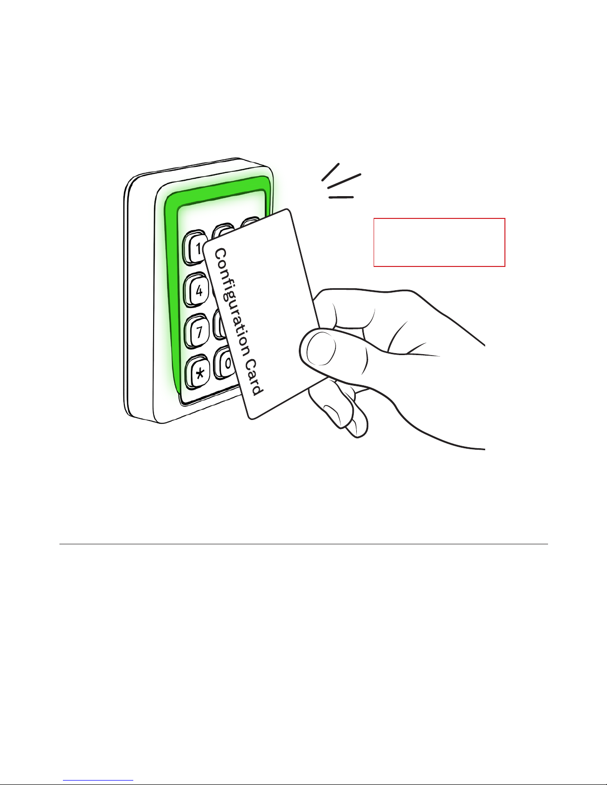
1: Set the reader in programming mode, see page: 18
2: Present the “Configuration Card” to the reader as shown. Keep
the card within reading distance until the reader beeps and blinks in
green. The reader is now programmed and ready for use according
to the configuration settings on the configuration card.
BEEP !
Configuring the reader
Reading distance
approximately 2 cm.
Page 20
20
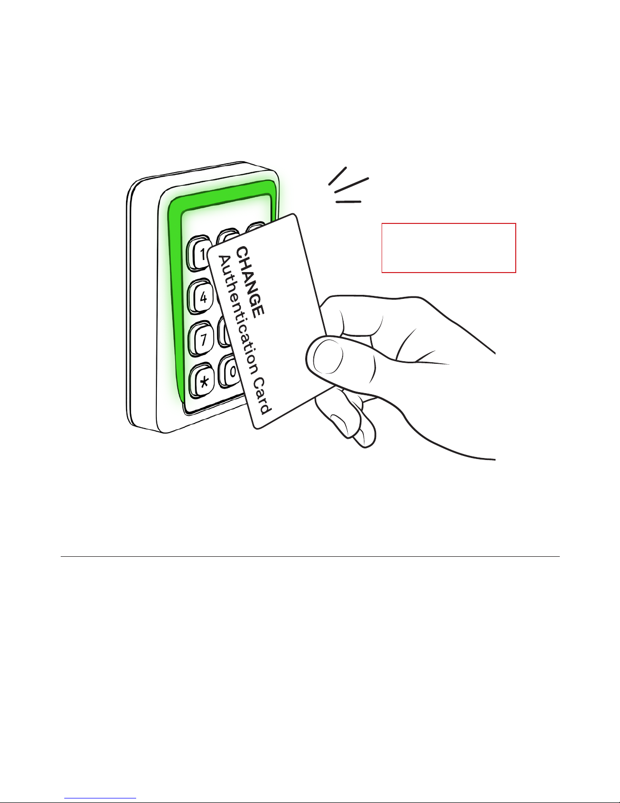
1: Set the reader in programming mode, see page: 18
2: Present the “CHANGE Authentication Card” to the reader as
shown. Keep the card within reading distance un til the reader beeps
and blinks in green. The reader is now reprogrammed to only be set
in programming mode by the new “Authentication Card”. The old
“Authentication Card” is no longer authorized to set the reader in
programming mode.
BEEP !
Changing authentication card
Reading distance
approximately 2 cm.
Page 21
21
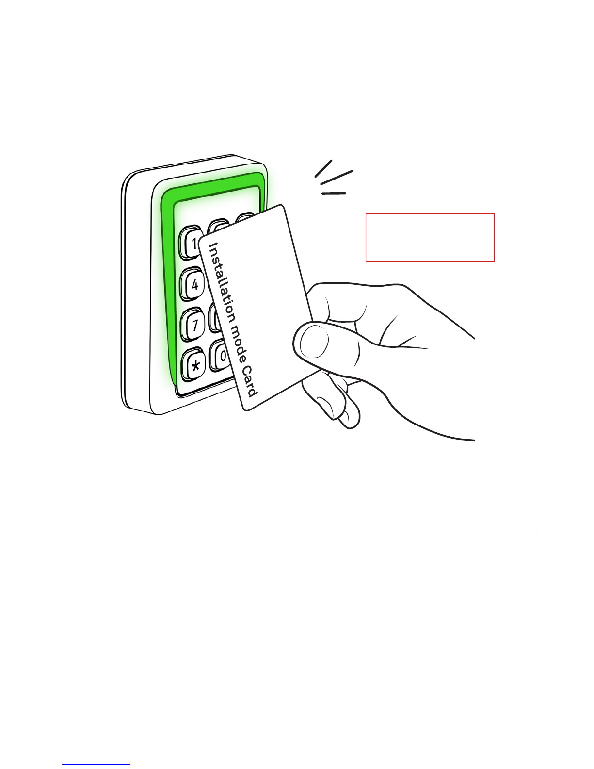
1: Set the reader in programming mode, see page: 18
2: Present the “OSDP Installation mode Card” to the reader as
shown. Keep the card within reading distance until the reader beeps
and blinks in green. The reader has now reset the secure channel
encryption keys to installation mode.
BEEP !
Resetting the OSDP
secure channel.
Reading distance
approximately 2 cm.
Page 22
22
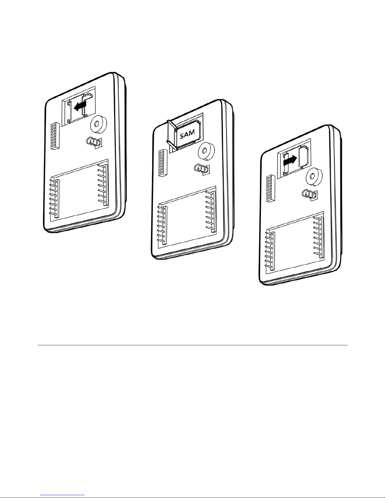
In order to install the SAM into the reader open the SAM socket by
unlocking and opening the lid. Then place the SAM into the socket
lock it into place by closing the lid and sliding it into locked position.
MIFARE® SAM AV2 (SIM Card), part no: SK2010
Software ISLOG SAM Manager, part no: PVISSAM-MGT
Installing Secure Access Module
Page 23

23
CIDRON
Accessories
Cidron Standard Reader
Cidron Combi Reader
Page 24
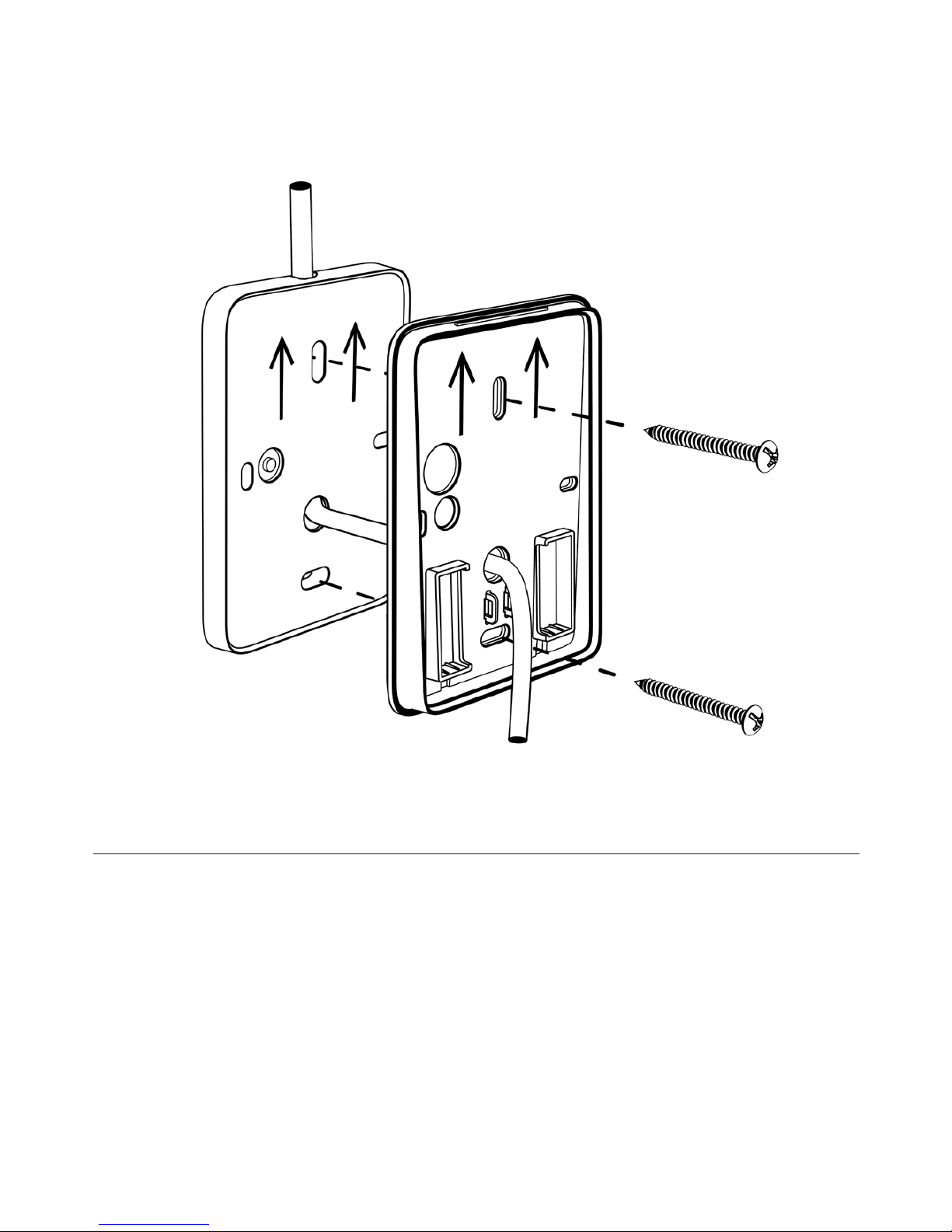
24
The distance plate can be used for example when installing readers in
environments where the installation surface is uneven or/and external
wiring at the same side as the reader. Can also be used when mounting
readers over installation boxes.
Distance plate, standard
Matte black, part no: SC9191-S
Matte white, part no: SC9191-V
Page 25
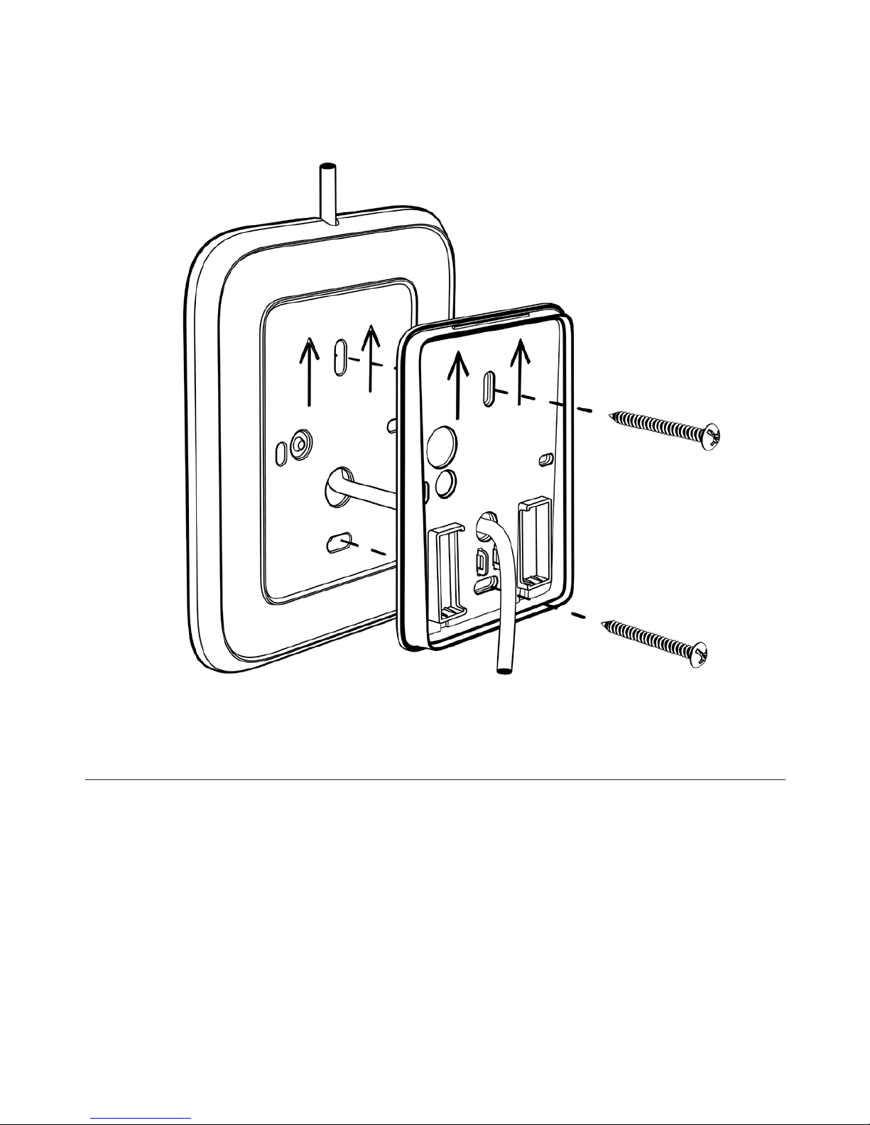
25
Used to install readers on an area where additional cover is
needed to hide old installation holes or on uneven surfaces.
Can also be used with external wiring on the same side as
the reader.
Distance plate, large
Matte black, part no: SC9197-S
Matte white, part no: SC9197-V
Page 26
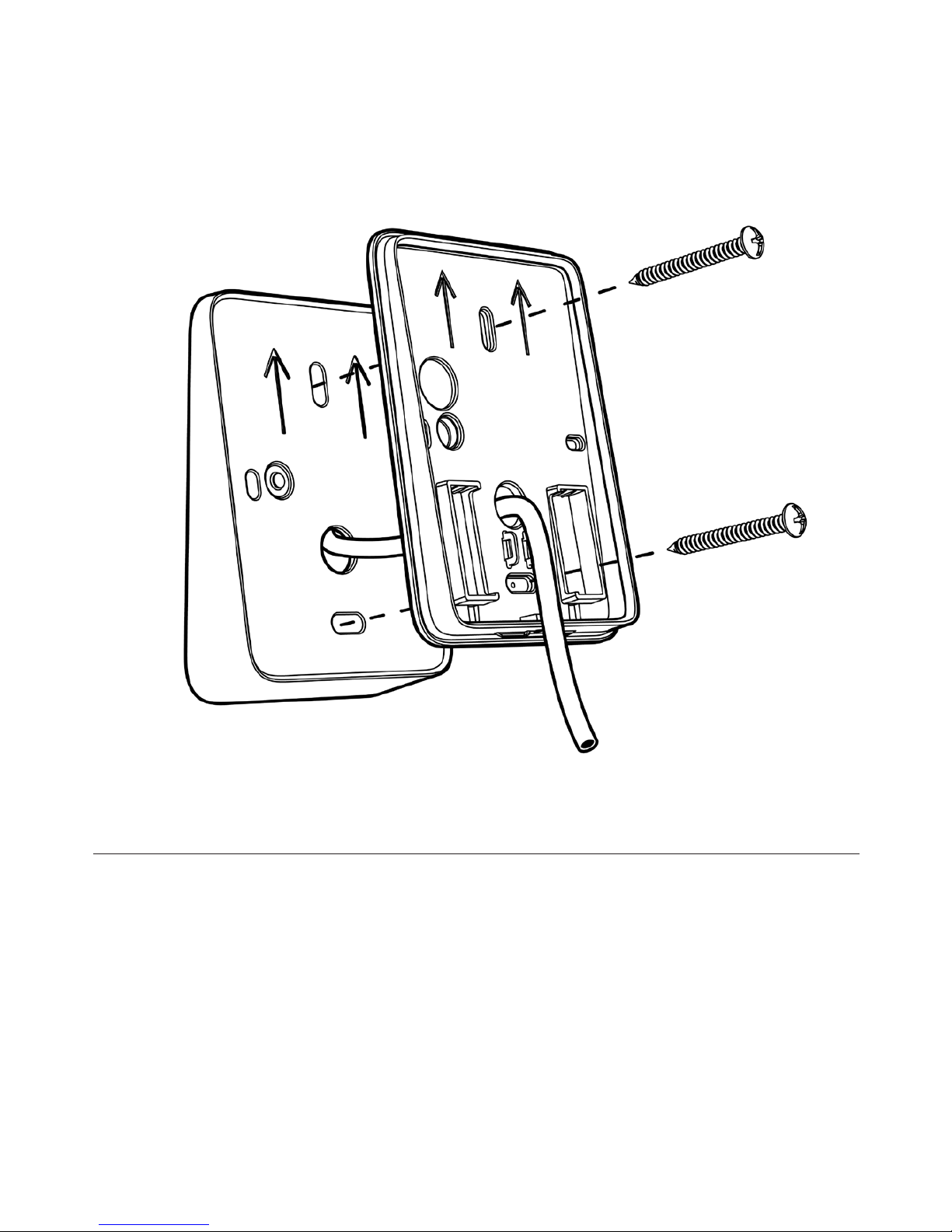
26
Used to increase accessibility as well as visibility of the keypad.
Distance plate, angled 10°
Matte black, art nr: SC9193-S
Matte white, art nr: SC9193-V
Page 27
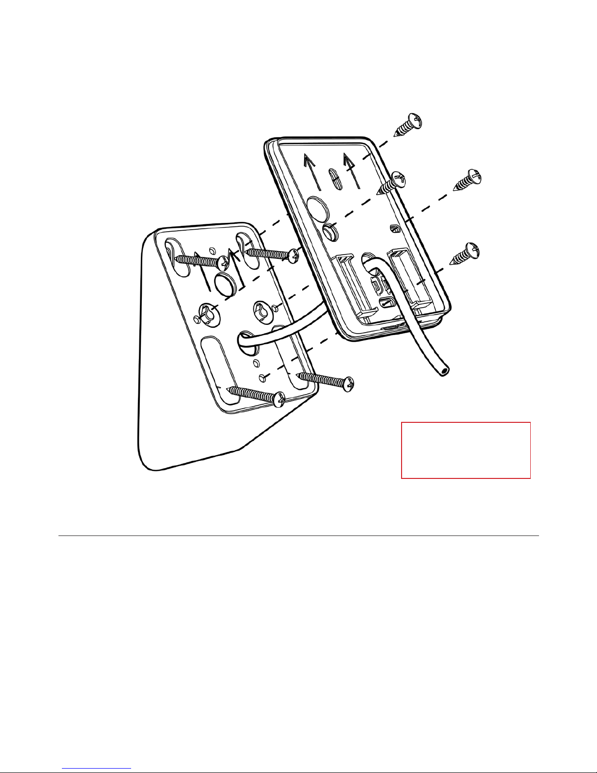
27
Used to increase accessibility as well as visibility of the keypad.
Recommended height is 900mm (center of reader) above the
ground/floor.
Note: The reader can also be installed turned around 180 degrees
for use on speed gates or tabletop readers, for instance.
Distance plate, angled 33°
* Screws and screw
plugs included with
accessory.
Matte black, art nr: SC9192-S
Page 28
28
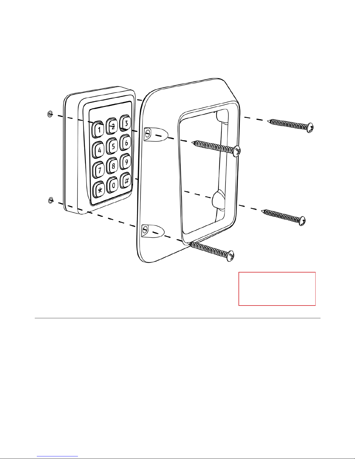
The vandalization protection is an accessory that shields the reader and
helps it withstand violence by absorbing and redirecting external forces
away from the reader. Can be retro-fitted to already installed readers.
Vandalization protection
* Screws and screw
plugs included with
accessory.
Matte black, part no: SC9180-S
Page 29
29
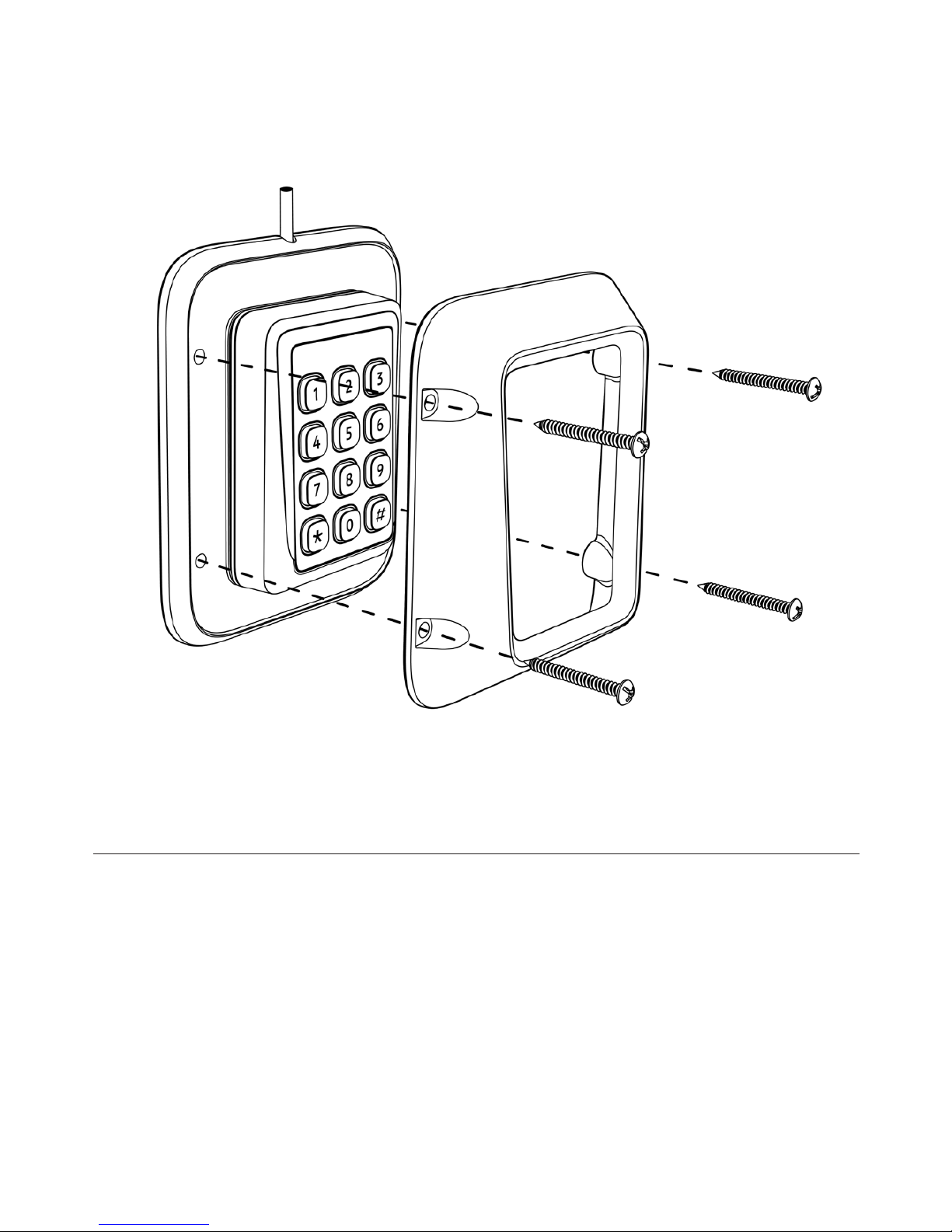
A recommended combination when external wiring is needed
together with the vandalization protection. Can also be used for
covering up old installation holes.
Mounting spacer large
+ Vandalization protection
Page 30
30
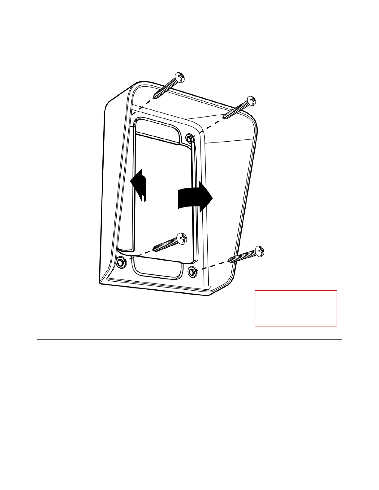
Used for increased protection from rain and snow, while still providing
great visibility and accessibility in a small format.
When installing the weather protection, use a pair of pliers to remove
the plastic break-off parts to fit your reader model.
Climate protection
* Screws and screw
plugs included with
accessory.
Transparent, part no: SC9901
Page 31

31
Use compressed air in between the buttons to remove dust and dirt
and after that Isopropyl alcohol can be used with a piece of fabric to
rub in between the buttons and the reader exterior.
Cleaning instructions
Page 32

SWEDEN
Nexus ID Solutions AB
Telefonvägen 26
126 26 Hägersten
Sweden
Tel: +46 8 685 45 60
[email protected]
nexusgroup.com
 Loading...