

Cichewicz Futura Bio 25*, Futura Bio 38*, Futura Bio 50 *, Futura Bio 75*, Futura Bio 100* Installation, Operation And Maintenance Instructions
...Page 1
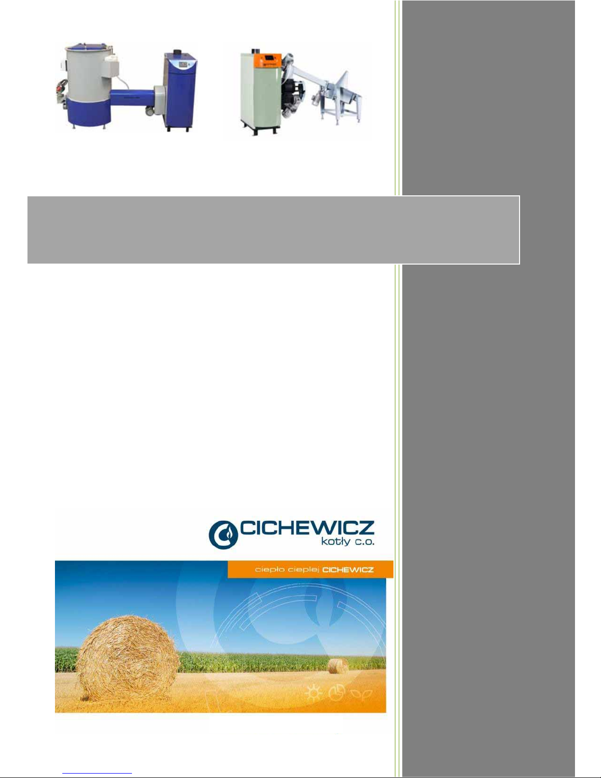
Futura Bio
Biomass-red hot water
boiler with automatic
fuel feeding system
Operating and maintenance manual
Installation, operation and maintenance instructions
Futura Bio Standard
With us heating
means saving…
Futura Bio Pellets
Congratulations on your purchase of a modern,
energy-saving, biomass-red boiler for central heating
purposes.
Basic fuel:
Futura BIO Standard boilers: sawdust briquettes, sawdust,
chips.
Futura BIO Pellets boilers: sawdust briquettes with the
diameter of 6-10 mm.
Please read this documentation carefully before
connecting and operating the product.
HEATING WITH BIOMASS
Page 2

2
1. Introduction
Thank you for choosing our Company and buying our product. We are convinced that our boiler will operate safely for many
The boilers of the Futura series are recommended for users seeking modern solutions in combustion of solid fuels.
This instruction manual contains all basic information concerning the design, installation and operation of your boiler. If you
read this instruction manual thoroughly and follow all instructions and recommendations, long-term and safe operation of the
boiler will be ensured.
We recommend entrusting the installation of your boiler to authorised installers, who are trained in the area of installation of
our boilers.
2. The purpose of Futura Bio series boilers
In Poland, biomass as the fuel for boilers becomes more and more popular and commonly used by entrepreneurs and
farmers. It is utilised for generating thermal energy during the process of combustion in special devices designed for this
purpose.
One of these devices is the Futura Bio series boiler in the Pellets or Standard version.
Purpose and possible use of Futura Bio series boilers
The Futura Bio boilers are designed for burning biomass
in the form of briquettes, sawdust and chips of proper size
and, as a substitute, grains or cherry stones.
The Bio Pellets version presented here is designed
for burning of pellets, i.e. granulated sawdust, with
diameter of 6 – 10 mm and up to 4 cm. Also, sawdust
can be burnt as a substitute. For special orders the boiler
in this version can be adopted for burning of wood chips as large as 30 mm.
The boiler may be installed both in new and revamped boiler rooms with the aim of combustion process automation,
improving the operating comfort and reducing of harmful emissions to atmosphere.
The Futura Bio boilers with built-in biomass burner can be used for heating of residential buildings, commercial
buildings, shops, detached houses and so on.
The Futura boilers may be installed only in open-radiant type systems with forced or gravitational circulation,
complying with the Polish standard PN-91/B-02413: ”Heating and heat engineering. Protection of open-type
water-based heating systems.”
All works related to boiler room equipment, boiler installation and operation must be performed in compliance
with valid standards and regulations.
Basic fuel for the Futura Bio Standard boilers:
For the Futura Bio Standard boiler with automatic fuel feeding the following fuels are recommended:
- Sawdust briquettes with diameter of 50 mm;
- Wood chips with maximum size of up to 3 cm;
- Sawdust with maximum content of non-combustible particles of 10%.
should not be less than 16 MJ/kg.
the lifetime of boiler.
Substitute fuel for Futura Bio Standard boilers:
- Corn straw briquettes with diameter of 50 mm (when not too hard, 80 mm is allowed),
- Grains: oat,
- Sweet and sour cherry pits.
Basic fuel for Futura Bio Pellets boiler:
The Futura Pellets series boilers are designed for burning of sawdust biomass in the form of pellets with the diameter of
6-10 mm and length of up to 50 mm.
Pellets should meet the requirements of the ÖNORM M7 135 standard.
Substitute fuel for Futura Bio Pellets boilers:
- Wood chips with maximum size of 25 mm.
Fuel recommendations:
Please remember that fuel pieces fed by the feeder should be of a proper size and fuel should not contain pieces greater
than maximum allowable size recommended. Furthermore, fuel must not contain foreign bodies like stones, plastic or
metal parts, cords, textiles, fabrics and so on).
Moisture content higher than recommended will accelerate the corrosion processes and cause premature wear of boiler
components. Damages caused by above mentioned reasons are not covered by manufacturer’s guarantee.
Page 3
3
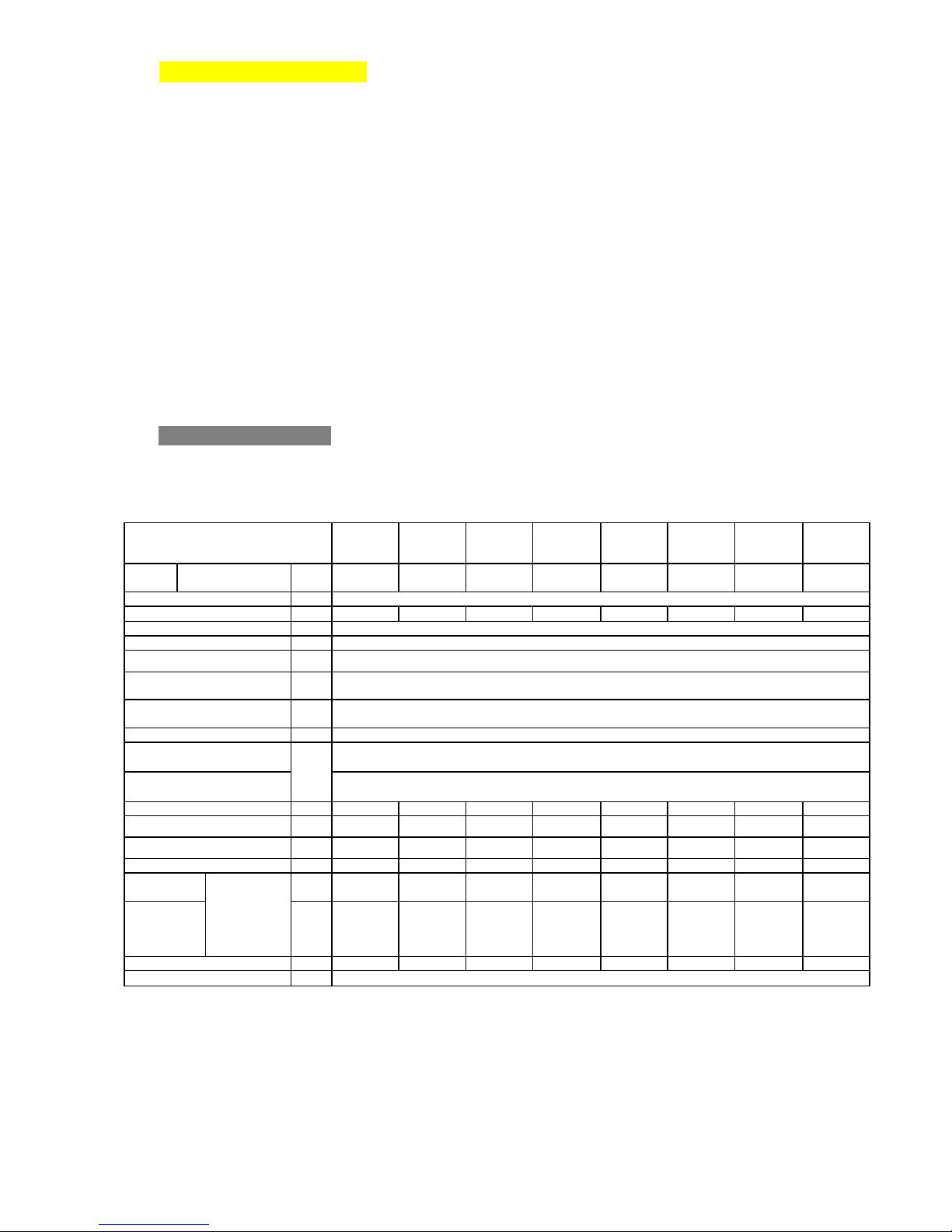
3. Design and specications
Futura Bio Standard
Futura
Bio 25*
Futura
Bio 38*
Futura
Bio 50 *
Futura
Bio 75*
Futura
Bio 100*
Futura
Bio 150*
Futura
Bio 250*
Futura
Bio 300
- 350*
25
38
50
75
100
150
200-250
300-350
%
78-82
dm3
120
155
190
260
360
470
1600
1820
bar
2
o
C
65
o
C
90
o
C
200 -340 oC
o C
100-140
Therm al eciency cla ss 3
mbar
2÷20
0.5÷5
Pa
15-20
15-20
20-25
20-25
25-30
25-30
25-30
30-35
m 8 8 8 8-10
8-10
12
14
14
cm2
400
400
400
600
600
600
1200
1500
dm3
620
620
620
1130
1130
1130
1130
Upon orde r
kg/h
6.9
10.5
13.8
20.7
27.6
41.4
55.2
82.9
h
51.2
33.7
25.6
31.1
23.3
15.6
11.7
-
W
850
850
850
850-2250
850-2250
850-2250
850-2250
850-2250
W
400
All data presented above is for information purposes only and is subject to changes due to continuous
product development.
*) Products available upon special order.
The boiler was designed on the basis of many years of experience, with focus on high thermal and operating comfort,
and with particular attention to protection of natural environment.
The boiler is designed in such a way that the parts being in contact with ue gas are also in contact with the water jacket
of the boiler.
The boiler is of a three-pass type with heat exchange occurring on the surface of hipped convection ducts or, in the case
of 200-250 and 300-350 kW models, vertical combustion tubes.
On the front side the boiler has a door to the combustion chamber, a hand hole for cleaning of convection ducts and,
in 25-200 kW, with ash box doors. The doors exposed to high temperatures are equipped with re protectors.
For sealing of doors a mineral bre stung is used.
The boiler body is made of certied steel grades and argon-arc welded.
The Futura Bio boilers are equipped with automatic burner with screw-type feeder.
The controller controls operation of the burner and feeder, the central heating pump and the hot water pump
and also communicates with the room thermostat. It is also possible to install a weather module which controls operation
of the mixing valve.
Optionally, the 25 kW models can be equipped with a safety coil, i.e. a device which evacuates excess heat.
Specications for Futura Bio Standard boilers
Boiler type
Wood chips
Sawdust briquettes
Boiler
power
Eciency
Water capacity
Maximum permissible pressure
Minimum inlet temperature
Maximum inlet temperature
Flue gas temperature
at rated power
Flue gas temperature
at minimum power
Emission eciency class
Water-side resistance
(pressure loss); Δt=10K
Water-side resistance
(pressure loss); Δt=20K
Chimney negative pressure
Recommended minimum
chimney height
Recommended chimney
cross-sectional area
Fuel tank capacity
Fuel
consumption
Approximate
working time
on one charge
of fuel
At rated power
and burning
of sawdust
briquettes
Power consumption (depending on version)
Heater power consumption (option)
Page 4
4
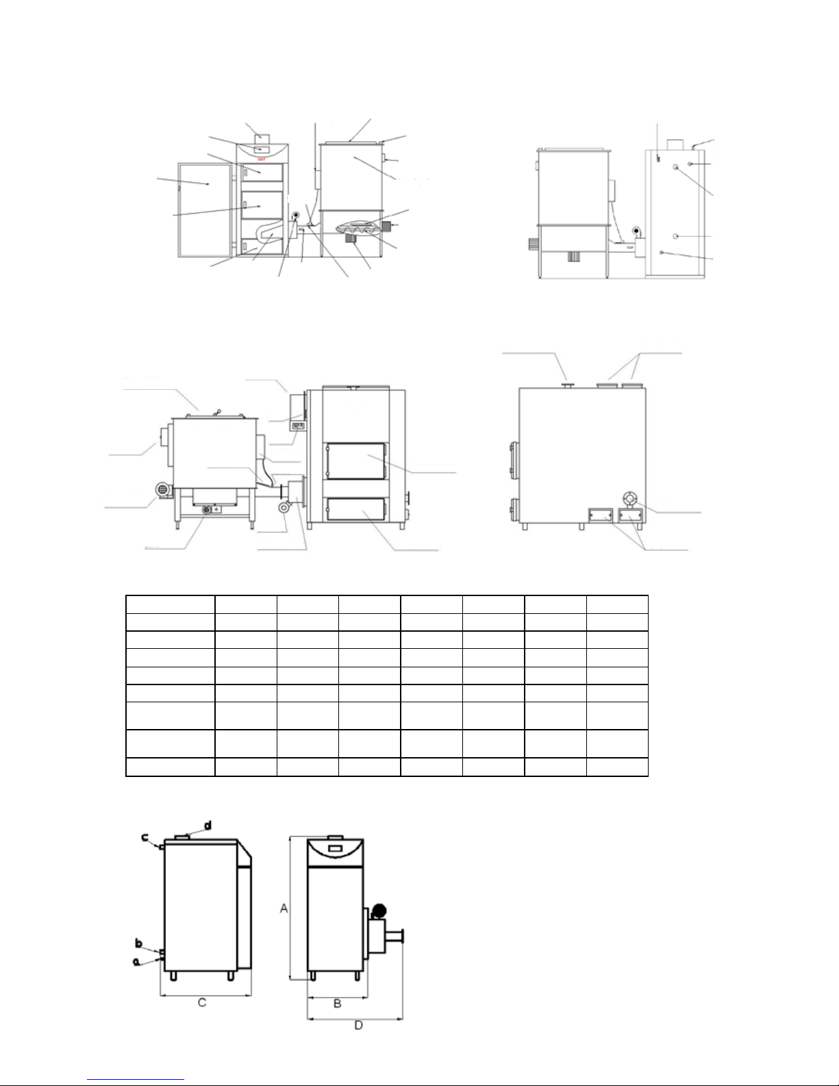
Figure: Schematic drawing of Futura Bio Standard boiler (model 25)
Dimens ions
25 50 75 100 150 200-250
300-350
A 1570 1660 1865 1895 1960
21 00
24 00
B 560 750 845 1010 1010
1550
1550
C 1025 1130 1310 1310 1350
3000
3000
D 850 1025 1265 1430 1435
1900
1900
a ½" ½" ½" ½" ½"
¾”
¾”
b 1 ½" 2" 2" 2" 2"
c 1 ½" 2" 2" 2" 2"
d 160 200 250 250 300
510x315
510x315
Figure: Boiler dimensions (25 kW models)
Masking door
(25 kW model only)
Combustion chamber door
Ash box door
Burner
Forced
draught fan
Feeder
temperature
sensor
Clean-out hole
Controller
Smoke conduit
Protection:
water tank
Loading door
Safety switches
Fuse box
Fuel tank
Mixer
Feeding screw
drive system
Feeding screw
Mixers’ drive
Protection: wax valve
Electrical connections
Safety coil
Stub pipe
for connecting
of ow-out
thermal protection
Return stub pipe
Drain stub pipe
Inlet stub pipe
Inlet stub pipe
Upper clean-out hole
Return stub pipe
Lower clean-out hole
BOILER
Feeder ap
with opening sensor
Flue gas outlet
FUEL FEEDER
Cleanout
/ inspection hole
STB
Controller
Water tank
Wax
protection
Forcing
fan
Burner with
built-in igniter
Furnace door
Ash box door
Fuel mixing drive
Fuel feeding drive
Electric switchgear
Figure: Schematic drawing of Bio Standard boilers, version 200-250
and 300-350 kW
Flange –
see drawing
Flange –
see drawing
Flange –
see drawing
Flange –
see drawing
Futura Bio St
clean-out
hole
Page 5
5
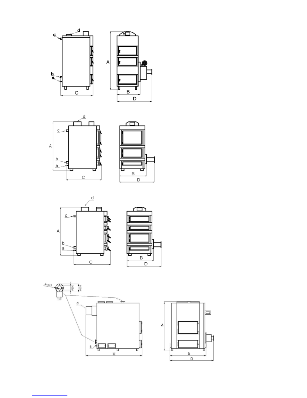
Figure: Boiler dimensions (50 kW models)
Figure: Boiler dimensions (75 kW and 100 kW models)
Figure: Boiler dimensions (150 kW models)
Figure: Boiler dimensions (200-250 and 300-350 kW models)
Page 6
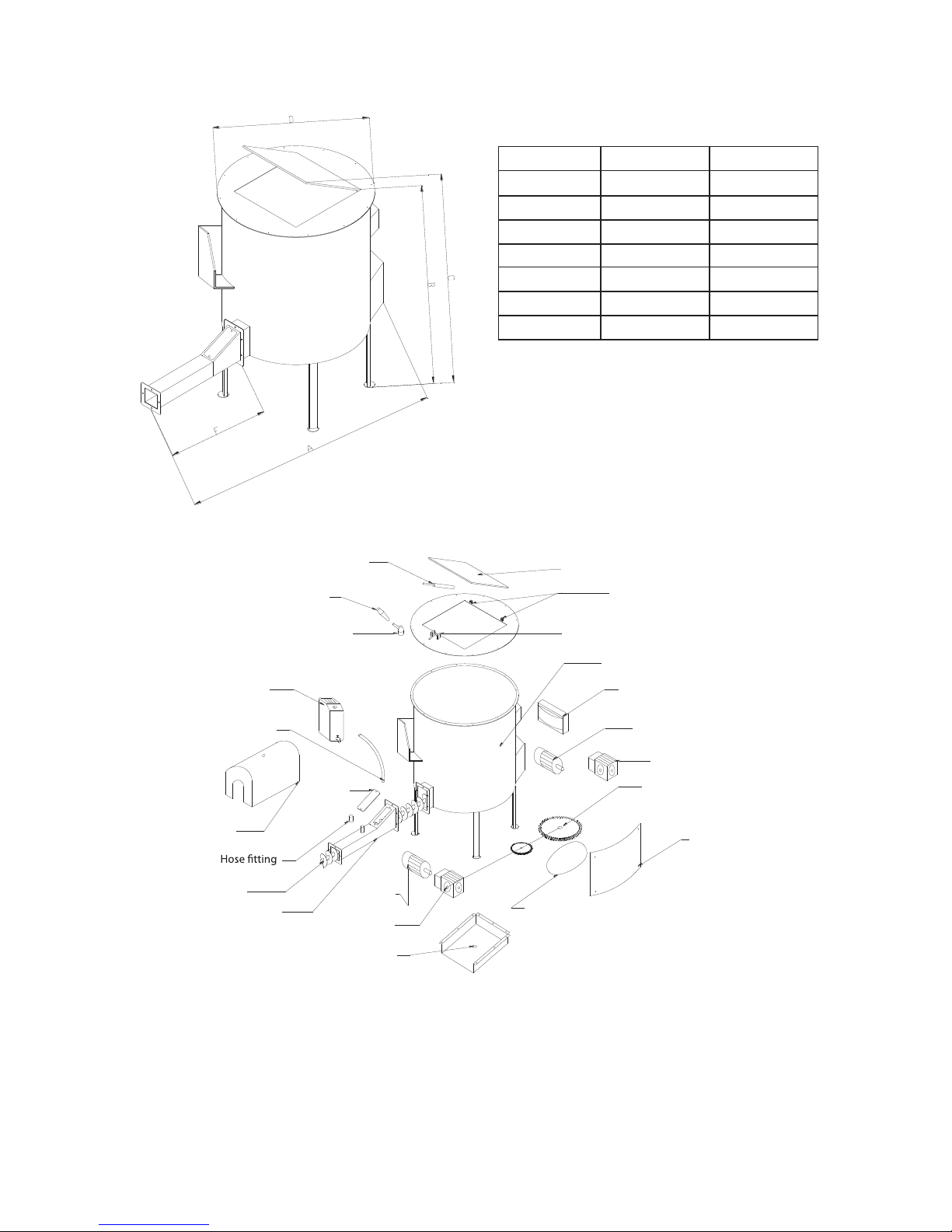
6
Fuel tank
Dimensions
25-50
75-200
A
2040 1950
A*
3040
2950
B
1600 1600
C
2300
2300
D
960
1270
F 740 360
F*
1740
1360
* for versions with extended feeding screw
Hinges
Actuator
Plasticized PVC knob
Hold-down clamp
Fuse box
Water tank
Rubber hose
Clean-out
hole
Gear cover
Feeder screw
Feeder screw
Motor
Mixer gear
Motor
Feeder gear
Tank
Locking device
Mixer toothed wheel
Feeder gear
Chain
BIO St basket
Tank lid
Feeder cover
Fuel tank –
– exploded view
Page 7
7
Futura Bio Pellets
Specications for Futura Bio Pellets boilers
Futura Bio
Pellets25*
Futura Bio
Pellets 100*
Futura Bio
Pellets 200 -
250*
Futura Bio
Pellets 300 -
350*
pellets kW
25 +/-8%
100+/-8%
200+250
300-350
%
82-86%
dm3
120
490
1600
1820
bar 2 2 2 2
o
C
55
55
55
55
o
C
85
85
85
85
o
C
180 -340oC
o C
100-140
mbar
2÷20
0.5÷5
Pa
15-20
20-25
20-30
30-40
m 8 10
12
14
cm2
400
600
800
1500
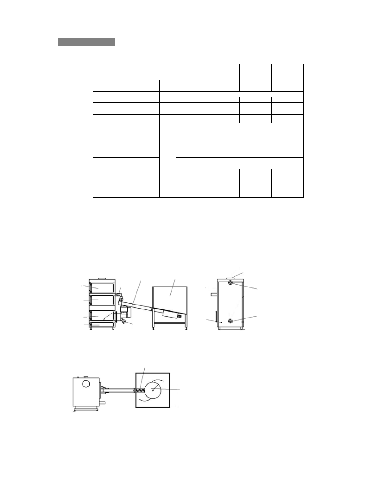
Figure: Schematic drawing of Futura Bio Pellets boiler
The Futura Bio Pellets boilers models 200-250 and 300-350 kW have identical design as Futura Bio Standard boilers,
models 200-250 and 300-350 kW (fuel tank as shown above).
*) Types available upon special order.
All data presented above is for information purposes only and is subject to changes due
to continuous product development. Dimensions of boiler and tank may dier from given above.
Boiler type
Boiler
power
Eciency
Water capacity
Maximum permissible pressure
Minimum inlet temperature
Maximum inlet temperature
Flue gas temperature
at rated power
Flue gas temperature
at minimum power
Water-side resistance
(pressure loss); Δt=10K
Water-side resistance
(pressure loss); Δt=20K
Chimney negative pressure
Recommended minimum
chimney height
Recommended chimney
cross-sectional area
Top
Screw
Mixer
Front Back
Combustion
chamber door
Ash box door
Clean-out door
(depending
on model)
Clean-out door
Boiler
controller
Feeding duct
Charging hopper
Fan
Drain
stub pipe
Return
stub pipe
Inlet
stub pipe
Smoke conduit
Page 8

8
Tank 2m3 Tank 3m3 Tank 5m3
Figure: Schematic perspective view
of the Futura Bio Pellets boiler
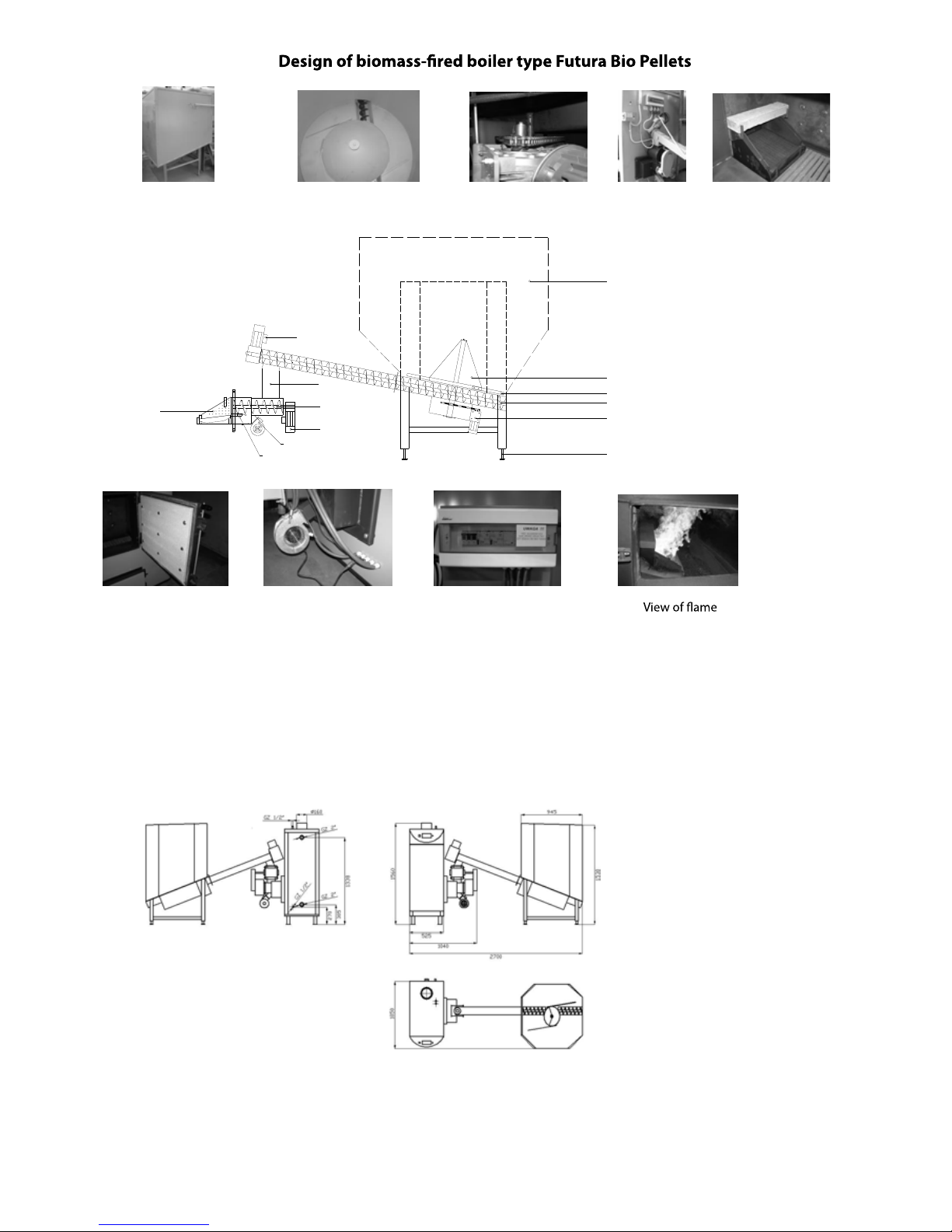
Design of biomass-red boiler with tank and screw feeder.
The drawings and photos presented below show the design of Futura Bio Pellets boiler with fuel tank
and feeding system.
Mounting of fuel tank in the Futura Bio Pellets boiler is made upon individual orders; the capacity and dimensions
of fuel tank is then matched to customer’s requirements.
Optionally, installing of automatic ash removal system is also possible.
Ash removal system Ash container
A system of 2 tanks
with external feeding system.
Page 9
9
1
2
3
4
5
6
7
8
9
10
11
12
13
1. Fuel tank installation space
2. Fuel mixer
3. Fuel mixer blades
4. Screw conveyor
5. Fuel mixer drive
6. Adjustable tank support
7. Fuel feeder drive
8. Charging duct
9. Burner charging feeder
10. Burner charging drive
11. Forced draught fan
12. Fuel igniter
13. Burner with cast-iron insert
Fuel tank Fuel mixer with
cone and blades
Mixer drive Burner charging
feeder drive
Burner with
cast iron insert
Furnace door Forced draught fan Electrical protection
Figure: Dimensions of Bio Pellets 25 kW boiler
Page 10

10
Top
Front BackLeft side
Figure: Dimensions of Bio Pellets 100 kW boiler
Figure: Dimensions of Bio Pellets 200-250 kW boiler
Page 11

11
Figure: Dimensions of Bio Pellets 300-350 kW boiler
4. Safety
5. Boiler installation procedure and installation requirements
The design of Futura Bio boilers incorporates modern solutions concerning solid fuel combustion.
To ensure safe operation and use of the boiler, please read this manual carefully and always follow the guidelines
and recommendations given in it.
The boiler is supplied with electric power 400 V / 50 Hz. Incorrect installation or improper repair may
endanger life or health by exposing to electric shock.
OCCUPATIONAL HEALTH AND SAFETY GUIDELINES
1. Prior to boiler start-up, read this operating and maintenance manual.
2. Before starting the boiler up, check if it was installed properly in both electric and hydraulic aspects.
3. Never use solvents, petrol or similar substances for lighting of fuel.
4. Never step into fuel tank and poke fuel manually when the boiler is operating.
5. Never open electric box or fuse box when the boiler is not disconnected from the electric power
source, otherwise a risk of electric shock may occur.
6. Fuel can be charged only when fuel feeder is stopped.
General requirements
The boiler room where the boiler is to be installed must meet the requirements of Polish standard
No. PN-87/B-02411.
Each boiler red with solid fuel has to be installed in accordance with valid standards and legal
regulations. Unauthorised modications of mechanical or electrical part of boiler structure will be
regarded as breach of warranty conditions causing its immediate termination.
First start-up of the boiler should be performed by authorised manufacturer’s service sta.
The heating system should be built according to the following guidelines:
a) The boiler should be installed in the open-type system.
b) The boiler should be installed at a safe distance from combustible or ammable materials.
c) Electric power supply is 400 V/ 50 Hz; the boiler should be electrically connected according to valid
regulations and standards by a qualied electrician who has all necessary licences.
d) The boiler should be connected to the chimney in compliance with valid regulations and
manufacturer’s recommendations.
e) A chimney draught regulator must be installed.
Page 12

12
The dimensions specied on above drawings are the minimum clearances necessary for uninterrupted
and comfortable operating and servicing of the boiler.
Requirements for boiler location
The boiler should be located in a place which meets the following re-ghting requirements:
— The boiler should be placed on a non-combustible surface.
— The boiler foundation must be made of non-combustible and heat-insulating material and must extend
beyond the boiler external dimensions at least 20 mm.
— If the boiler is to be located in a basement, it is required to locate it on a pedestal with the height not less than
50 mm above oor level. Both the boiler and fuel tank should stand vertically and be precisely levelled.
Safe distance to inammable materials
— During boiler installation and operation the minimum distance of 200 mm to medium-ammable
materials should be maintained.
— In the case of very ammable materials like paper, wood, plastics and so on (ammability class
C3), this safe distance must be increased to 400 mm.
— If the inammability of materials is very high, the safe distances specied above must be doubled.
Flammability classes of materials
The boiler location should ensure easy access for maintenance and service operations:
• On the charging hopper side the clearance distance of at least 1000 mm must be maintained (whenever
possible, it is the best to have such clearance equal to the length of charging hopper together with feeding
duct).
• The clearance between back side of the boiler and boiler room wall should not be less than 400 mm.
• It is essential to ensure easy access to connection points for hydraulic system, chimney and electric power
supply (3 x 400 V / 50 Hz).
Figure: Boiler location scheme
Minimum boiler
depth + 300mm
Flammability class Material
Sandstone, concrete, brick, plasterwork made of inammable material, ceramic tiles, granite
Cement-wood substrate, glass bres
Beech wood, oak wood, plywood
Pine wood, larch wood, spruce wood, cork, rubber substrate
Asphalt, celluloid, polyurethane, polystyrene, plastics, PVC
A – non-ammable
B – partially ammable
C1 – hardly ammable
C2 – moderately ammable
C3 – highly ammable
Page 13
13
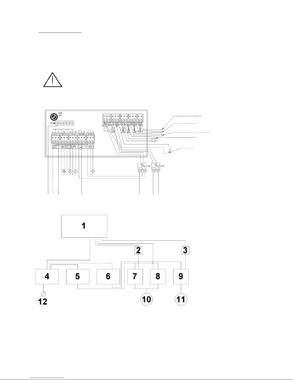
1. RK-2006 B controller
2. UM-1 module
3. UM-1 module
4. Circuit breaker type IS 25 or 40
5. Protection - 0,63 up to 8 A
6. Protection 0,63 up to 8 A
7. Contactor 25 A
8. Contactor 25 A
9. Contactor 25 A
10. Three-phase motor 0,18-3 kW
11. Three-phase motor 0,18-3 kW
12. Power supply line, 400 V
Drawing: Electric wiring diagram
Drawing: Wiring diagram for basic controller type RK 2006L2B
Minimum distances to building partitions, dependant on the boiler power, are specied by relevant regulations
concerning in-house boiler rooms red with solid fuels.
Electrical connections
The external devices and auxiliary equipment of the boiler should be electrically connected by qualied electrician with
the appropriate licences. The external equipment and boiler accessories, if any, should be connected, according to the
markings, to power supply outputs located on the back cover of boiler housing. Electric diagram is also included in
instruction manual for the controller.
• Power supply: 400 V / 50 Hz.
• Outputs for external devices: 230 V.
The boiler itself should be connected to a separate power line protected by fast-acting cut-out with nominal current of 16 A.
No other electric al devices may be connected to the line supplying the boiler!
The electric cables must be thoroughly xed along their entire length and must not touch boiler water jacket or ue gas
outlet.
Prior to any repairs the electric supply must be disconnected.
Water jacket temperature sensor
Feeder sensor
Domestic hot water temperature sensor
Room thermostat
Limit switch
IGNITER
PUMPS
DOMESTIC HOT WATER
CENTRAL HEATING
L BLACK
N BLUE
PE YELLOW/GREEN
Page 14
14
CHT
PI
H
RP
RP
RW
RO
CTwp
F
ZZ
Pco
F
Pco
RB/RW
TP
RB
ZZ
ZRC
ZT
PI
H
CHT
RW
RP
RP
RO
Pco
F ZZ
ZTM-t
RB/RW
RB
TP
ZT
ZRC
Hydraulic connection
Hydraulic connection consists in connecting the system supply and return pipes to appropriate stub pipes
of the boiler.
Recommendations concerning installation of the boiler:
• The system must meet all valid legal regulations, codes and conform to the best building practices.
• The boiler can be operated only in open-type heating systems meeting the requirements of Polish
standard PN-91/B-02413 concerning protection of open-system water heating devices and expansion
vessels.
• No isolating valves are allowed between the boiler and expansion vessel.
• The hydraulic system of boiler room must ensure the minimum return water temperature at the level of
55 oC. The requirement can be met e.g. by using three-way temperature valves (like the valves type TV
manufactured by ESBE Company), mixing pump or other devices able to ensure the required return
temperature automatically.
• During boiler operation, the recommended temperature difference between supply and return is
10-20 oC.
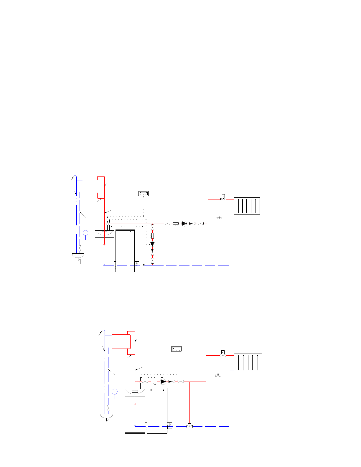
Exemplary schemes of hydraulic connection
Radiator-type central heating system with one heating loop and mixing pump
Radiator-type central heating system with one heating loop and mixing valve
Expansion
vessel
Expansion
vessel
HEATING LOOP
HEATING LOOP
Page 15
15
RB
H
PI
CHT
RO
RW
RP
RP
ZZ
ZTM-t
KS
Pco
F
ZZ
Pcwu
F
ZZ
RB/RW
TP
CTcwu
cwu
ZT
ZRC
zwu
F
RC
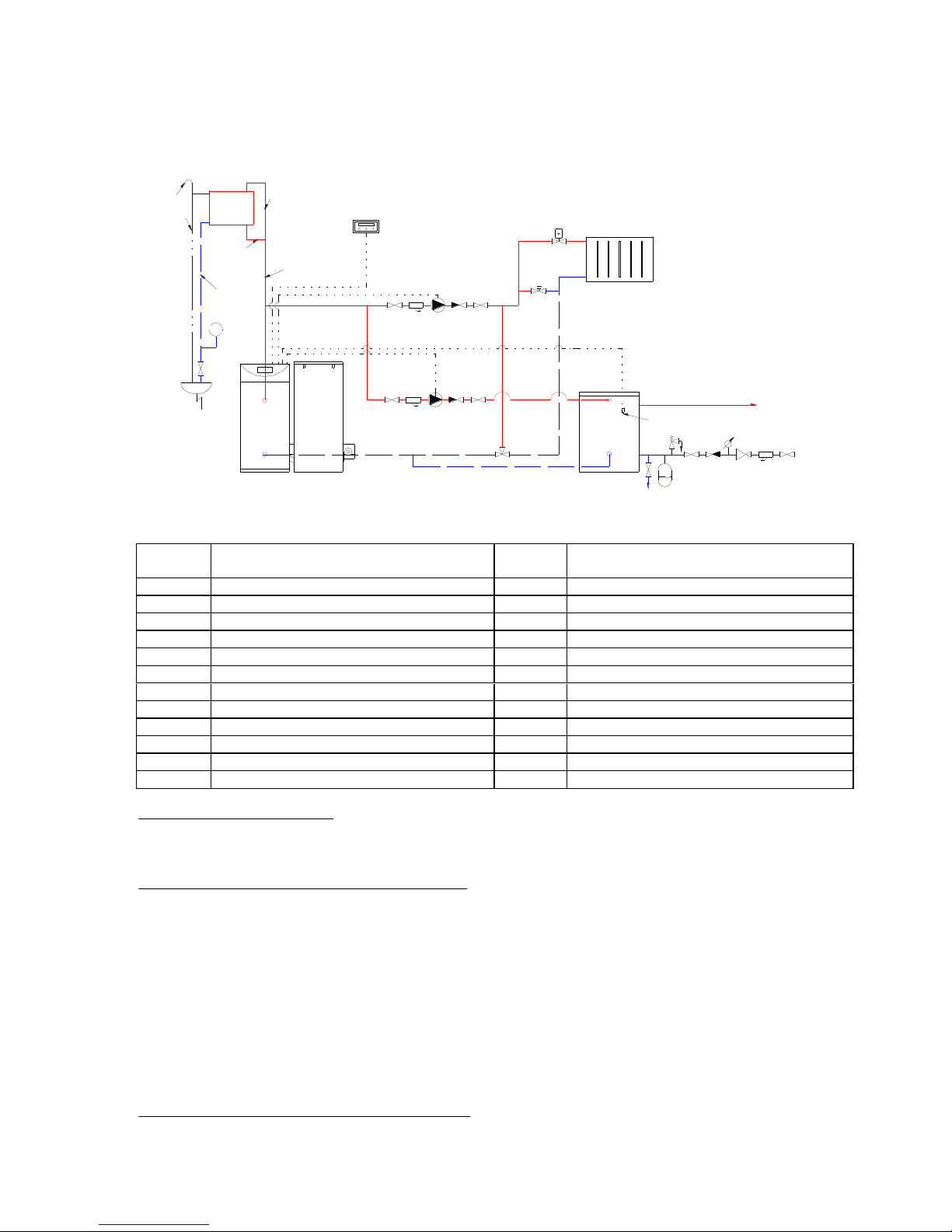
Oznaczenia na s chematach
co
ZTM -t
cwu
ZT
RW
ZB
RB
zwu
RP
NPW
RS
KS
RO
O
Pco
RC
Pcwu
zwu
Tp
MN
F
ZZ
ZRC
Expansion
vessel
HEATING LOOP
Domestic
hot water
storage vessel
Radiator-type central heating system with one heating loop, mixing valve and storage-type water heater
Central heating
Domestic hot water
Expansion pipe
Safety pipe
Overow pipe
Tell-tale pipe
Vent pipe
Central heating water circulation pump
Domestic hot water storage vessel lling pump
Room thermostat
Filter
Check valve
Pressure dierential valve
Thermostatic radiator valve
Safety valve
Domestic cold water
Domestic water membrane-type expansion vessel
Drain valve
Vent
Pressure reducer
Domestic cold water
Pressure gauge
Three-way mixing valve (thermostatic valve)
Requirements for boiler water
Water used for lling the boiler and central heating system should meet the requirements of PN-93/C-04607 standard.
Connection of safety coil (option for 25 kW model).
Safety temperature limiting device (cooling coil, heat exchanger):
Safety temperature limiter (STB) protects the boiler against overheating in case of interruption of water circulation (e.g.
power outage) and cannot be used for preparation of domestic water. The device has supply and return lines. The
return line should be connected to the drain to cooling sump, and supply line with cold water pipe.
Specications for safety temperature limiting device:
Minimum supply pressure: 2 bar
Maximum working pressure: 6 bar
Connection: ½”, male thread
Installation of safety temperature limiter (optional)
Models equipped with STB have this device built-in at the factory.
Page 16
16
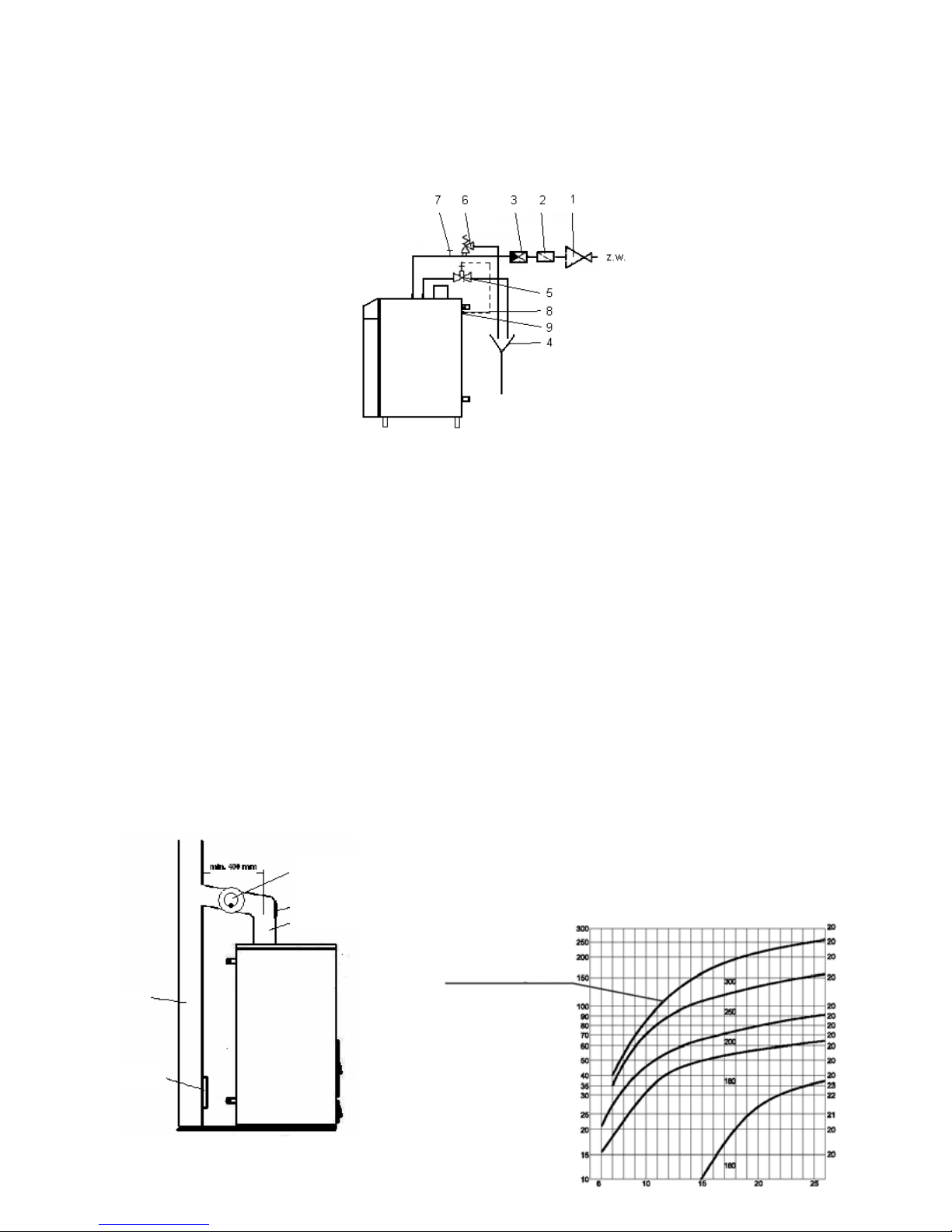
Other equipment, i.e. thermal outow protection, safety valve, check valve and cleaning funnel must be accessible
after the installation is nished. Since for functional test the drain must be visible, the drain funnel should be used!
Figure: Connection of safety temperature limiting device
Minimum supply pressure for safety temperature limiting device: 2 bar
The connection must not be isolated (closed) manually.
1. Pressure regulating valve (only for connection to water supply with pressure above 6 bars).
2. Filter.
3. Check (non-return) valve.
4. Drain funnel.
5. Thermal outow protecting valve (opens at temperature of 95 - 98 ºC), i.e. type SYR 3065.
6. Safety valve.
7. Cleaning funnel.
8. Thermal outow protection sensor (temperature-controlled valve).
9. Connector for connecting the thermal outow protection sensor.
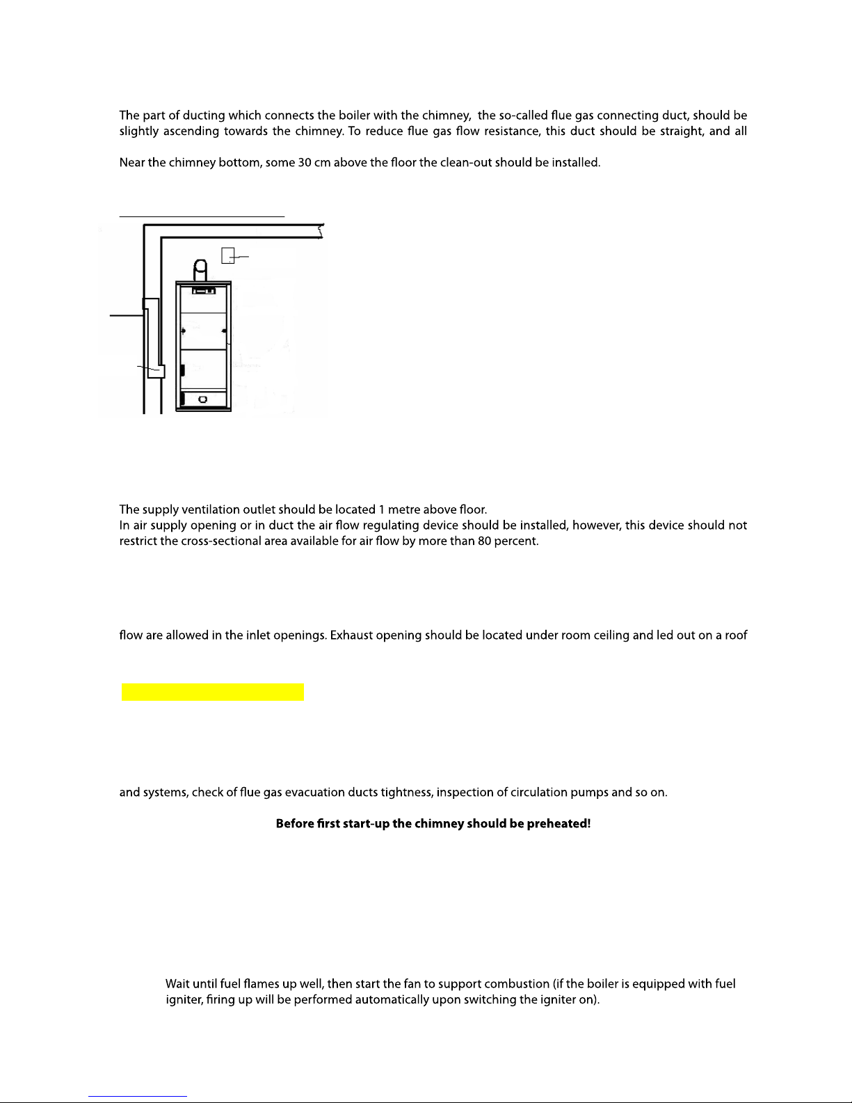
Flue gas ducts should be built in accordance with currently valid
regulations.
Negative pressure in the chimney should be maintained at the level
specied in the Table. Chimney diameter can be selected using the graph
below.
The chimney diameter must not be less than the diameter of ue gas
connecting duct.
Connecting to the chimney
Figure: Connecting to the chimney
Draught regulator
with explosion
door
Clean-out hole
Flue gas connecting duct
Chimney
Clean-out hole
Inner diameter
of ue duct [mm]
Boiler power [kW]
Chimney height [m]
Required draught [Pa]
Page 17
17
The manufacturer recommends application of the chimney systems which are resistant to condensate
soaking-through. The chimney should be made of acid-resistant materials and thermally insulated along its entire
length.
necessary changes in direction, if any, should be made in the form of gentle bends.
The manufacturer also requires installing the draught regulator and explosion door in the chimney system.
Ventilation of boiler room
According to regulations to ensure users’ safety and proper operation of
boilers each in-house boiler room has to be equipped with supply and
exhaust ventilation. When there is no supply ventilation at all or the
existing one is choked, in most cases the boiler will operate incorrectly
(excess smoking, water condensation, inability to reach higher
temperatures), while the purpose of exhaust ventilation is to evacuate
used air and harmful gases from the boiler room. In boiler rooms
equipped with natural draught chimney the mechanical ventilation is
not allowed.
Figure: Ventilation in the boiler room.
Supply ventilation.
The supply ventilation duct should have the cross-sectional area equal to one-half of chimney cross-section area, but
its dimensions should never be less than 20 x 20 cm.
The air supply duct should be made of non-combustible material.
Exhaust ventilation
The exhaust ventilation channel should be made of brick, with cross-sectional area equal to at least 25% of chimney
cross-sectional area, but with dimensions not smaller than 14 x 14 cm. No devices restricting the area available for air
by at least 1.5 metre. The duct should be made of incombustible material.
Commissioning
First start-up is carried out by authorised manufacturer’s technicians (payable service).
The initial works carried out in order to prepare the boiler for start-up should include the general inspection of
technical condition of boiler room, installations and systems, including inspection and control of boiler equipment
Futura Bio Standard.
Firing up
1. Fill the tank with fuel.
2. Connect the boiler to power supply line (put the cable plug into a wall socket).
3. Start manual fuel feeding mode until fuel appears in the burner (see the controller instruction manual).
4. Light up fuel on the burner by using paper and small pieces of wood or other kindling material.
6. Operation of the boiler
Supply
ventilation
Exhaust
ventilation
Page 18

18
fuel feeding time and intervals between fuel feeding operations during start-up and working cycle (see
instruction manual for boiler controller).
6. Fuel feeding times should be so programmed that the previous fuel portion burns completely before the
fuel does not pour through into ash box and the embers do not move backwards to the feeder. It is the
best when combustion takes place on two-thirds of burner’s surface area.
may go out.
8. Also, it is necessary to adjust the volume of combustion air fed to the boiler by adequate setting of the fan
operation (using fan shutter or from controller level). The volume of air should be so adjusted that the
9. Periodically (at least once a week) check the settings of fuel feeder and burner, as well as the combustion
process in the boiler.
Damping
to ash box.
Then empty the ash box from ash and remaining embers and close the boiler door.
occur.
Futura Bio Pellet
Firing up
1. Fill the tank with fuel.
2. Connect the boiler to power supply line (put the cable plug into wall socket).
quantity of starting fuel portion, fuel feeding time and intervals between fuel feeding operations during
start-up and working cycle for minimum and maximum boiler output (see instruction manual for boiler
controller).
6. Fuel feeding times should be so programmed that the previous fuel portion burns completely before the
fuel does not pour through into ash box and the embers do not move backwards to the feeder. It is the
best when combustion takes place on two-thirds of burner’s surface area.
may go out.
8. Also, it is necessary to adjust the volume of combustion air fed to the boiler by adequate setting of the fan
operation (using fan shutter or from controller level). The volume of air should be so adjusted that the
9. Periodically (at least once a week) check the settings of fuel feeder and burner, as well as the combustion
process in the boiler.
After initial adjustment the controller will automatically adjust the metering of fuel and air for the set
boiler output.
Damping
automatically. The burner damps each time the set temperature is reached.
Attention: Combustion of various fuels on grates under the burner may cause burner damage. These grates
are designed for burning the remaining embers from the burner and are not intended for continuous
combustion.
Note:
water and the valve open, so as water remains in tubing.
In case of water depletion in the tank, check the tightness of wax plug located on the feeder. If leaks are
found, remove used wax and pout in a new one.
Page 19
19
Periodically check the amount of water in the tank.
burner and temperature of water in the boiler are to be checked.
Boiler daily maintenance:
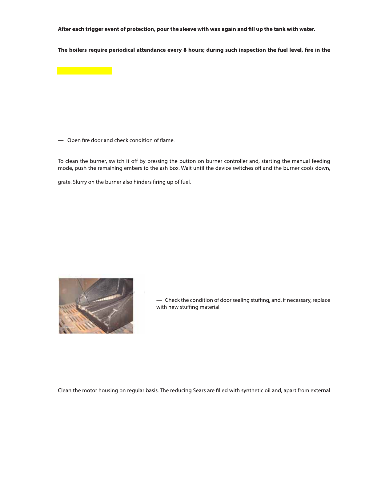
— Includes checking of fuel quantity in fuel tank and removal of ash.
— Ash should be removed each 3 – 7 days, depending on the boiler working load and ash content in fuel.
In case of fuel containing greater amount of impurities the burner should be cleaned from carbon deposits once a
day.
Outer surface of boiler housing should be cleaned by using slightly damped cloth and cleaning detergents.
Weekly maintenance:
— Periodically remove slag, if appears in the furnace of burner in large amount.
Depending on fuel quality, the burner can be cleaned every several days or weeks.
then open the door and remove ash and slurry which can possibly choke the air supply openings from burner’s
Monthly maintenance:
Perform weekly maintenance operations, and then:
— Damp the boiler and inspect heat exchange walls for deposits.
To this end, open the clean-out door or unscrew cover (two versions) and check thickness of deposit on boiler walls.
The models above j 150 kW have two clean-out holes.
If thickness of deposit exceeds 1.5 - 2 mm, cleaning is necessary. Clean using steel brush, and remove scraped
deposit from convection channels. Depending on the model, clean out holes are located on the front, top or side
of the boiler. For boilers above 100 kW it is recommended to clean them every two weeks at least.
Walls of combustion chamber can be cleaned through charging door.
— Check if there isn’t too much waste material in charging hopper and remove if necessary.
— Once a month the boiler should be damped, ceramic and cast iron
parts of the burner removed and cleaned from impurities.
— Check the patency of air nozzles in the burner, clean if necessary.
Air duct in the burner can be cleaned after rem
oving the outer part of
burner.
It is recommended to use combustion catalysts which facilitate burning
of soot on boiler walls and reduce emission of carbon dioxide to
atmosphere. When using such agents, the boiler can be cleaned less
frequently. The agent should be poured to the burner every several days.
Maintenance of feeder
In the boiler is left inoperative for a prolonged period of time, then:
— Once three months start the feeder for 15 minutes, to avoid jamming of screw inside pipe.
— Clean the pipe from fuel remainders, empty the tank and clean the burner.
The feeder is so designed that expensive maintenance is not necessary. The feeder should be cleaned from dust or
remaining of fuel or ash on time from time basis.
cleaning, do not require any maintenance. Never use solvents for cleaning, since such liquids may damage sealing
rings.
On a current basis, check the reducing gear operation. Also, check the following:
— Condition of seals – no leakages of oil or grease are allowed.
— Noise level – increase of operating noise can iondicate the damage of motor or gear-motor bearings.
— Smoothness of running – if operation is not smooth, the cause can be in gear motor or the screw driven.
7. Maintenance
Burner grates
BIO
burner
Page 20
20
— Condition of threaded connections – tighten if necessary.
— Surface condition. Periodically clean the motor from impurities and dirt which can hinder heat exchange.
— At least once three months lubricate the moving element of the boiler (gears with chain, hinges and so on).
Motor
The motor bearings are of closed type and are lubricated with long-term grease, therefore in normal conditions the
bearings do not need maintenance or re-lubricating for the period of 20.000 working hours, but no longer than
three years.
Upon expiration of above period of time it is recommended to replace motor bearings.
Reducing gear
The reducing gear is lled with synthetic oil which, in normal conditions, should be replaced every 20,000 working
hours, but at least every three years.
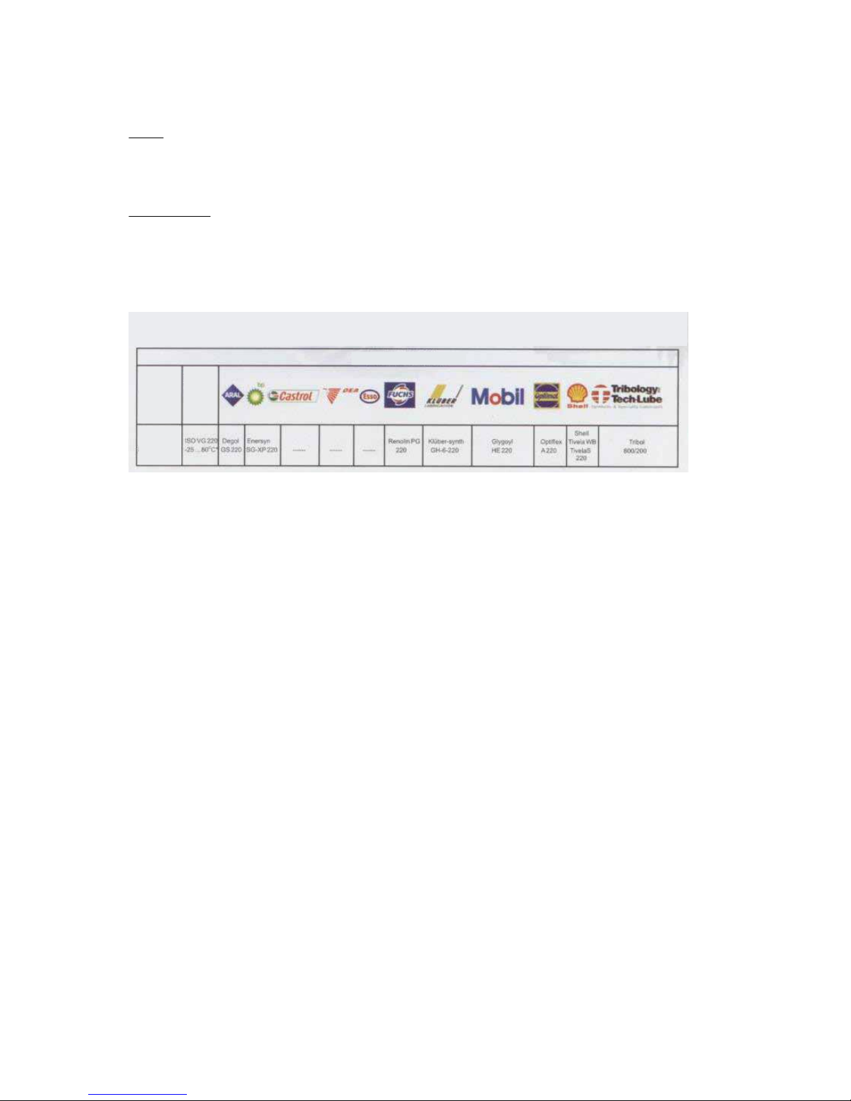
If oil replacement is necessary, please use one of oils specied below:
The table below species lubricants that can be used for lubricating of worm gear-motors:
Oil type
Oil
type
Working
temperature
range
Synthetic
oil
 Loading...