

Page 1

Installation
Operation
Commissioning
Maintenance
10 - 2011
NA 07.108 D
V30
Page 2
EN - 1
EN
CONTENTS Page
General information 1
Operation 2
Operating instructions 2
ECO external switch/Frost protection 3
Air temperature measurement 4
Water temperature measurement 4
Switch parameter settings 5
Application details 7
Electric heater management 9
Unit installation 11
Technical specifications 11
LED operation 11
Flush-mounted unit 12
Wall-mounted unit 12
General information
CIAT’s V30 control is designed for use with system-powered air conditioning terminal units (fan-coil units, UTA, cassettes etc.) in 2 pipe, 2
pipe/2 wire or 4 pipe applications using recirculated air.
There are two types of V30 controls:
- those controlled by air acting on the ventilation
- those controlled by water acting on 230V thermo motor valves and on the ventilation.
V30 is available in a wall-mounted version (to be connected by the installer) or built-in version (fitted and connected in the factory)
Main functions:
- Controls a manual 3-speed fan.
- Automatic heating/cooling switching with changeover sensor.
- Potential-free input for a window contact, timer or presence sensor.
- Three speeds: Comfort/Economy/Frost protection.
N.B.: built-in version on Major Line CV, vertical casing
For a 2 way or 4 way valve kit, the switches located at the
rear of the V30 thermostat must be reset (see section entitled “Switch settings”).
Page 3
EN - 2
Operation
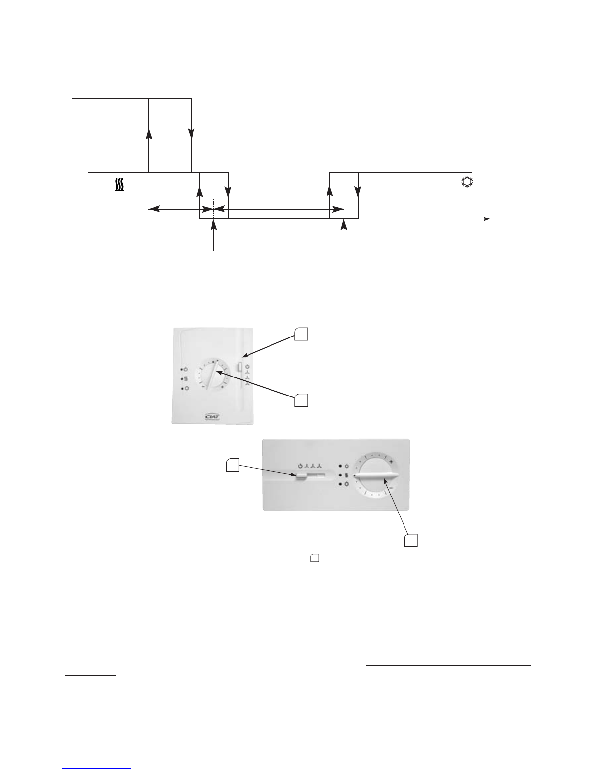
On/off control.
* See possible applications for electric heater management (Section entitled: Electric heater management)
-3°K
Electric heater*
Valve
Valve
Neutral zone 4/6°K
Room or return air
temperature
Hot setpoint
19°C
Cold setpoint
23 or 25°C
Operating instructions
Setting the setpoint temperature:
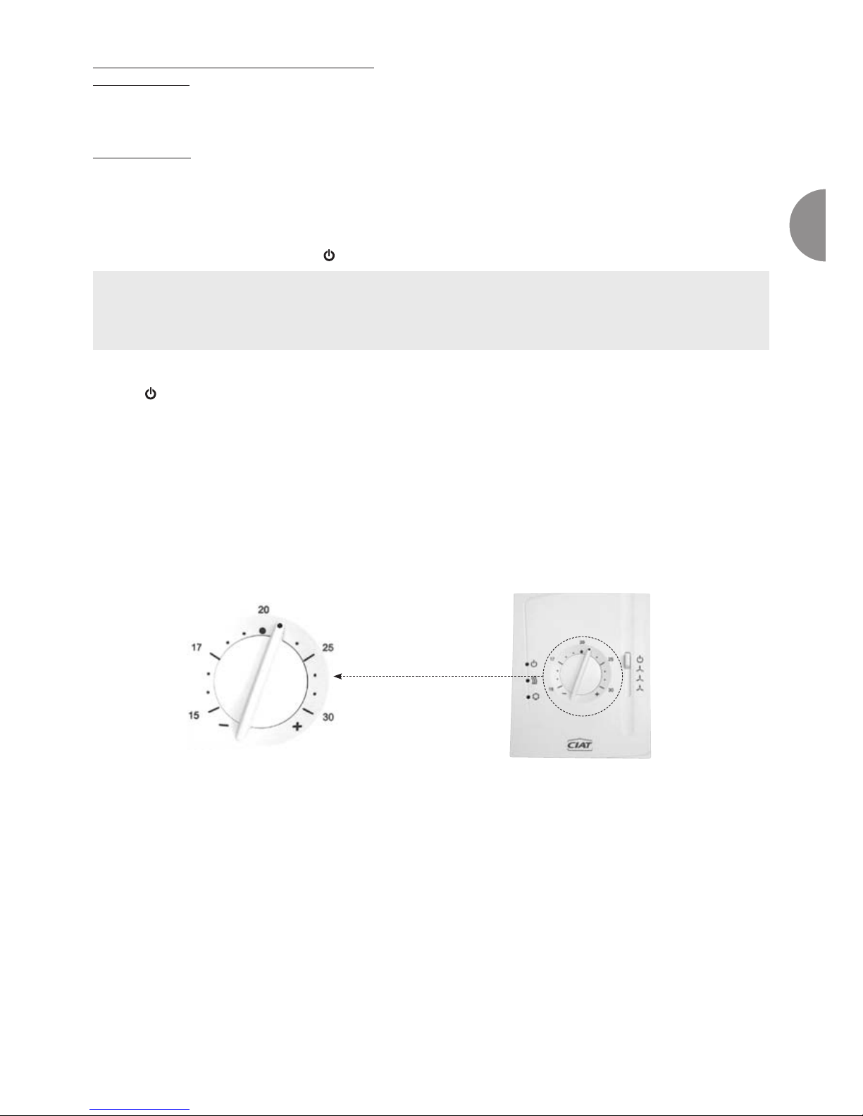
The setpoint temperature can be set by adjusting the ± on the dial
1
- On the comfort setting, at the centre point, the hot setpoint is 19°C and the cold setpoint is 23°C or 25°C.
The setpoint values can be set within a range of ± 6°C.
- The neutral zone is 4 or 6K depending on the setting selected.
- On the economy setting, both the hot and cold setpoints are automatically offset by 5°C in relation
to the comfort setpoint indicated by the position on the dial
- The frost protection setpoint is set to 8°C
Setting the fan:
- The user may choose between 3 manual fan speeds by using the button
Special information for controlling an electric
heater button:
- If the user selects the low fan speed, the electric heating cycle rate is limited to 50%.
- If the user selects the medium speed, the cycle rate is limited to 80%.
Limiting the cycle rate prevents the appliance from overheating.
Wall-mounted unit
with
dial
1
2
Built-in unit (connected to
the fan coil unit)
with dial
1
2
Page 4
EN - 3
EN
Note on Neutral zone fan in Comfort mode only:
Setting: S.6=OFF: stop fan in neutral zone: with a built-in unit and S.6=OFF, periodic ventilation is carried out every 60 minutes
and engages the fan for 1 minute on low speed.
This periodic ventilation prevents stratification and enables better irrigation of the return sensor.
This sequence is also carried out on the wall-mounted thermostat, if a return air temperature sensor is connected to terminals 8-9.
Setting S.6 = ON: Permanent ventilation in deadband:
The fan continues to operate at the speed set using the selector
Post ventilation safety period:
This is activated automatically in the following phases:
- When exiting heating or cooling mode, the fan continues to operate at low speed for approximately 2 minutes, thereby ensuring
post ventilation safety.
- When the thermostat is stopped (position
) there is also a 2-minute post ventilation safety period at low speed.
Setting the operating speed:
Position automatically changes the thermostat to frost protection mode (+8°C) (with fan on low speed only).
Because post ventilation is a safety measure, once started it will override all of the controller’s other actions. If the On/Off selector
and/or dial are moved while the post ventilation safety process is active on the controller, the V30 will remain inoperative until the
2-minute period has elapsed. Once the safety period is complete, the V30 starts operating again normally in heating or cooling
mode, or at the selected speed.
N.B.: These values, which aim to help understand how the dial works, simply give an indication of the selected
temperature. There will be a slight difference between the value at which the dial is set and the actual
temperature in the room, depending on the chosen settings (possible setting of the neutral zone of 4/6°K, with the thermostat
set to hot or cold).
Eco external switch/frost protection
An On/Off input enables the thermostat to be switched remotely to economy or frost protection mode
(configurable). The direction of operation for this input can be adjusted (normally open or normally closed).
This is a potential-free input which should have no voltage. It is not possible to connect several controls in parallel
on the same switch. Also, if there is a timer present, the installer should allow for a relay board to be fitted.
Setting the Summer/Winter changeover:
The summer/winter changeover can be set in two different ways:
- Automatically, using the changeover sensor which measures water temperature
- Remotely using a control line (On/Off switch).
n Switch open: COOLING mode
n Switch closed: HEATING mode
n Wall thermostat, hotel version
A version is available with graduation in degrees on the dial.
The maximum length of the line is 10 meters. The connection should be made so as to ensure there is an extra-
low voltage for safety (TBTS according to standard C15-100) and to limit the length of the wires.
Page 5

EN - 4
N.B.: This schematic diagram is needed for changing from comfort mode to “Eco” mode as standard (to “frost
protection” mode by on-site adjustment). It is strictly forbidden to carry out timed programming by switching off the
thermostat power supply.
N
P
K1 K2 K3 K4
CF CF CF CF
Air temperature measurement:
- A built-in thermostat regulates air temperature using a return sensor.
- A wall thermostat regulates air temperature:
n By either using an indoor environment sensor (built into the unit)
n Or by using a return sensor.
For a wall thermostat, particular attention must be paid to the position of the thermostat in the room (do not expose
it to the sun, or place it above an appliance which releases heat, place it on an inside wall). The end of the wiring conduit must be
heat insulated.
Some Values:
The return and changeover sensors have the same specifications.
Temperature
°C
5 10 15 20 25 30 35
Resistance
ohm 22,050 17,960 14,690 12,090 10,000 8,313 6,940
150 cm
150 cm
20 cm
min.
150 cm
20 cm
min.
Water temperature measurement
The 2 pipe or 2 pipe + 2 wire fan coil units may have a water temperature measurement sensor (or changeover
sensor). It should be placed upline of the 4-way valve (water network side) by the installer. It is fitted to the pipe using
electrician’s clips and must be insulated
Clamping collars Sensor adapter
Sensor
Water inlet pipe
Insulation
Sensor
Valve motor
3-way valve
with built-in
bypass
(often called a
4-way valve)
Schematic diagram of connection with timer
Page 6
EN - 5
EN
N.B.: the changeover sensor measures the surface temperature of the pipe. There is an obvious difference between
the actual water temperature and the surface temperature.
The water speed will therefore be selected so as to guarantee changeover switching.
n If the changeover input is left “open” (nothing is connected between terminals 10 and 11) the thermostat deduces that the
water circulating in the heater is still cold.
n If there is a bridge between these terminals, the thermostat deduces that the water is still hot.
Switch parameter settings
Operating algorithm in the changeover sensor:
The V30 specifically manages the changeover so as to continuously optimise the room temperature control:
*If the C/O sensor measures a water temperature which is 7°C more than the room temperature, the water is
considered to be hot.
*If the C/O sensor measures a water temperature which is 4°C less than the room temperature, the water is
considered to be cold.
*If the C/O sensor measures a water temperature between these two values, the water will be considered to be
neutral.
Operation of the V30 with neutral water temperature:
In this scenario, the V30 authorises opening of the valve every hour in order to check the water network temperature:
*If this temperature does not change, the V30 remains as it is.
*If this temperature varies and returns to the conditions described above, the V30 will authorise its control cycle
again.
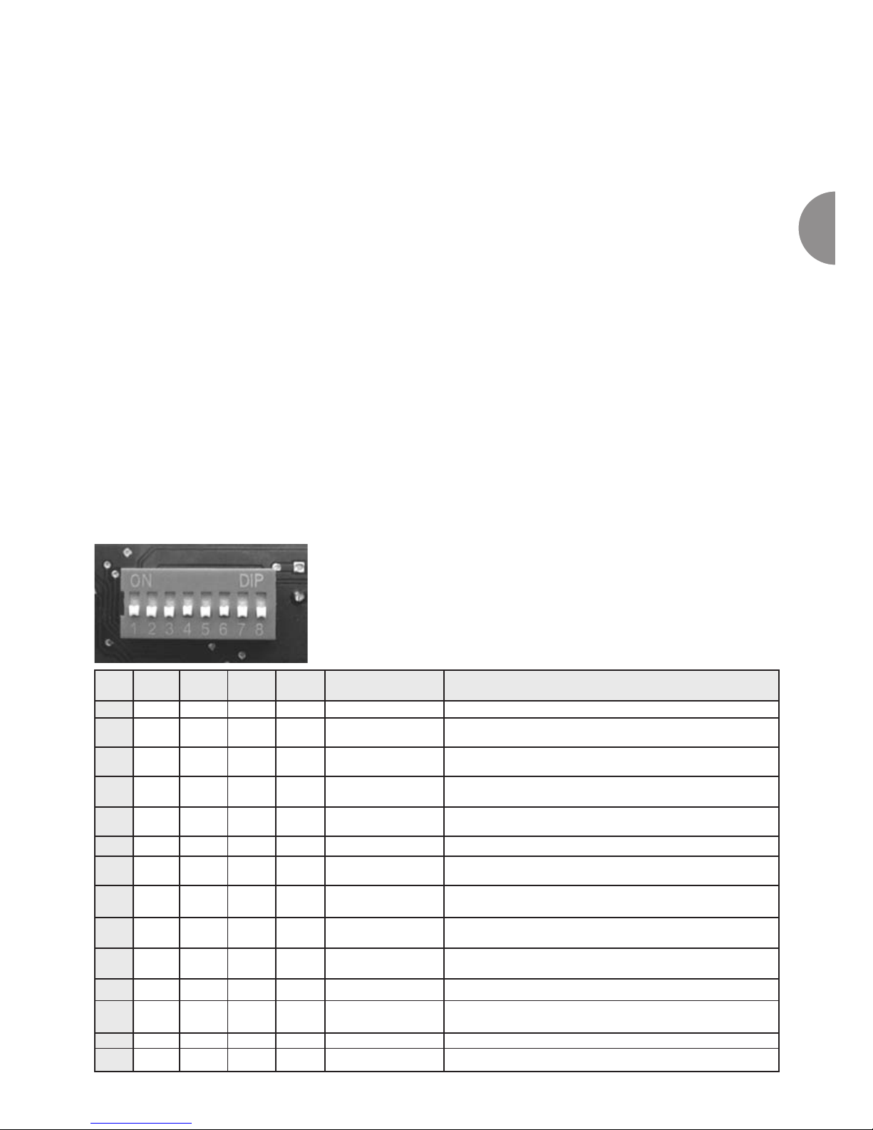
No. 1 2 3 4 Regulation on Application
A
ON ON ON OFF Air 2 Pipes
B
ON ON ON ON Air
2 Pipes + electric heater for
main heating
C
OFF OFF ON ON Air
2 Pipes + electric heater for
additional hot water
D
ON ON OFF ON Air
2 Pipes + Electric heater for main heating and for
additional hot water
E
ON OFF ON ON Air
2 Pipes (cold only) + Electric
heater with control line
F
OFF OFF OFF OFF Air + Water 2 Pipes
G
OFF ON ON OFF Air + Water
2 Pipes + electric heater for
main heating
H
OFF OFF ON OFF Air + Water
2 Pipes + electric heater for
auxiliary hot water
I
ON ON OFF OFF Air + Water
2 Pipes + Electric heater for main heating and for
additional hot water
J
ON OFF ON OFF Air + Water
2 Pipes (cold only) + Electric
heater with control line
K
OFF ON OFF OFF Air + Water 2 Pipes (cold only) + radiator
L
OFF ON OFF ON Air + Water
2 pipes (cold only) + radiator
with control line
M
ON OFF OFF OFF Air + Water 4 Pipes
N
ON OFF OFF ON Air + Water 4 Pipes with control line
Page 7
EN - 6
No. Function OFF ON
5
Neutral zone 6K 4K
6
Neutral zone ventilation in comfort mode Off On
7
Mode allocated to window contact input Economy Frost protection
8
Active direction of the window contact input Normally open Normally closed
To confirm a switch modification, the appliance must be switched off.
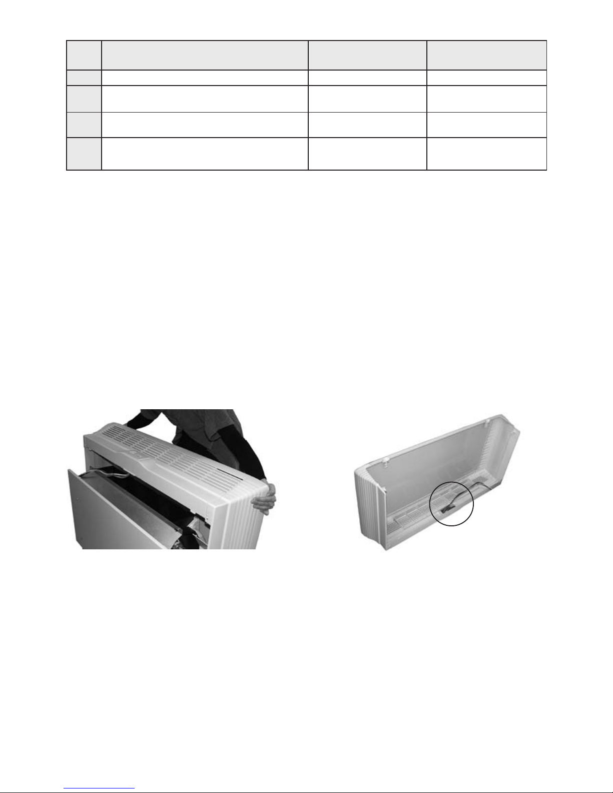
«Reconfiguring the switches on a V30 built into a vertical cased Major Line:
- Before carrying out any operation on the V30 switch off the appliance by turning off the power supply.
- Remove the Major Line’s casing
- As the V30 controller is not fixed to the device’s frame, it remains integrated with the casing.
- Remove the casing/thermostat assembly (fig.1).
- Turn the casing over to access the thermostat (fig.2).
- Adjust the switches located behind the thermostat
- Connect any water temperature and air temperature sensors to the fast-on connector:
Terminals 1-2 for the air temperature sensor corresponding to the COM - NTC inlet on the V30.
Terminals 3-4 for the water temperature sensor corresponding to the COM - CO inlet on the V30.
(see diagram of the built-in V30 thermostat on page 26 and the wiring diagram which corresponds to your
application).»
Fig.1
Fig.2
Page 8
EN - 7
EN
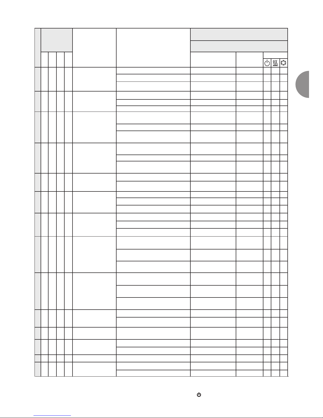
Application details
Application
Switch
setting
Application
Input
Changeover (C/O)
Comfort Mode**
Heating mode
S1 S2 S3 S4
Action
Ventilation
(3 speeds)
LED
A
ON ON ON OFF 2 Pipes (without valve)
Closed or the sensor detects hot water No valve Ventilation ON ON ON OFF
Open or the sensor detects cold water ON OFF OFF
The sensor detects neither hot nor cold water ON OFF OFF
B
ON ON ON ON
2 Pipes (without valve)
+ electric heater
for main heating
Closed or the sensor detects hot water No valve Ventilation ON ON ON OFF
Open or the sensor detects cold water ON OFF OFF
The sensor detects neither hot nor cold water Electric heater Ventilation ON ON ON OFF
C
OFF OFF ON ON
2 Pipes (without valve) +
auxiliary electric heater
Closed or the sensor detects hot water
Electric heater
as 2nd stage
Ventilation ON ON ON OFF
Open or the sensor detects cold water ON OFF OFF
The sensor detects neither hot nor cold water ON OFF OFF
D
ON ON OFF ON
2 Pipes (without valve)
+ electric heater used as main
heater
and also auxiliary
Closed or the sensor detects hot water
Electric heater
as 2nd stage
Ventilation ON ON ON OFF
Open or the sensor detects cold water ON OFF OFF
The sensor detects neither hot nor cold water
Electric heater
as main stage
Ventilation ON ON ON OFF
E
ON OFF ON ON
2 pipes (cold only)
+ electric heater,
with control line, without valve
LP contact closed Electric heater Ventilation ON ON ON OFF
LP contact open ON OFF OFF
F
OFF OFF OFF OFF 2 pipes (with valve)
Closed or the sensor detects hot water Valve Ventilation ON ON ON OFF
Open or the sensor detects cold water ON OFF OFF
The sensor detects neither hot nor cold water ON OFF OFF
G
OFF ON ON OFF
2 pipes (with valve)
+ electric heater
in main heating
Closed or the sensor detects hot water Valve Ventilation ON ON ON OFF
Open or the sensor detects cold water Electric heater Ventilation ON ON ON OFF
The sensor detects neither hot nor cold water Electric heater Ventilation ON ON ON OFF
H
OFF OFF ON OFF
2 pipes (with valve)
+ auxiliary electric
heater
Closed or the sensor detects hot water
Valve + electric heater as 2nd
stage
Ventilation ON ON ON OFF
Open or the sensor detects cold water ON OFF OFF
The sensor detects neither hot nor cold water ON OFF OFF
I
ON ON OFF OFF
2 pipes (with valve)
+ electric heater used as main
and auxiliary heater
Closed or the sensor detects hot water
Valve + electric heater as 2nd
stage
Ventilation ON ON ON OFF
Open or the sensor detects cold water
Electric heater
as main stage
Ventilation ON ON ON OFF
The sensor detects neither hot nor cold water
Electric heater
as main heater
Ventilation ON ON ON OFF
J
ON OFF ON OFF
2 pipes (cold only)
+ electric heater,
with control line and valve
LP contact closed Electric heater Ventilation ON ON ON OFF
LP contact open ON OFF OFF
K
OFF ON OFF OFF
2 pipes (cold only)
+ radiator
Heating valve Ventilation OFF ON ON OFF
L
OFF ON OFF ON
2 pipes (cold only)
+ radiator with control line
LP contact closed Heating valve Ventilation OFF ON ON OFF
LP contact open ON OFF OFF
M
ON OFF OFF OFF 4 pipes Heating valve Ventilation ON ON ON OFF
N
ON OFF OFF ON 4 pipes with control line
LP contact closed Heating valve Ventilation ON ON ON OFF
LP contact open ON OFF OFF
LP = control line *BL. : Flashing
** In economy mode: operation identical to Comfort mode with:
- Setpoint offset by +/-5°C
- LED
: OFF
Page 9
EN - 8
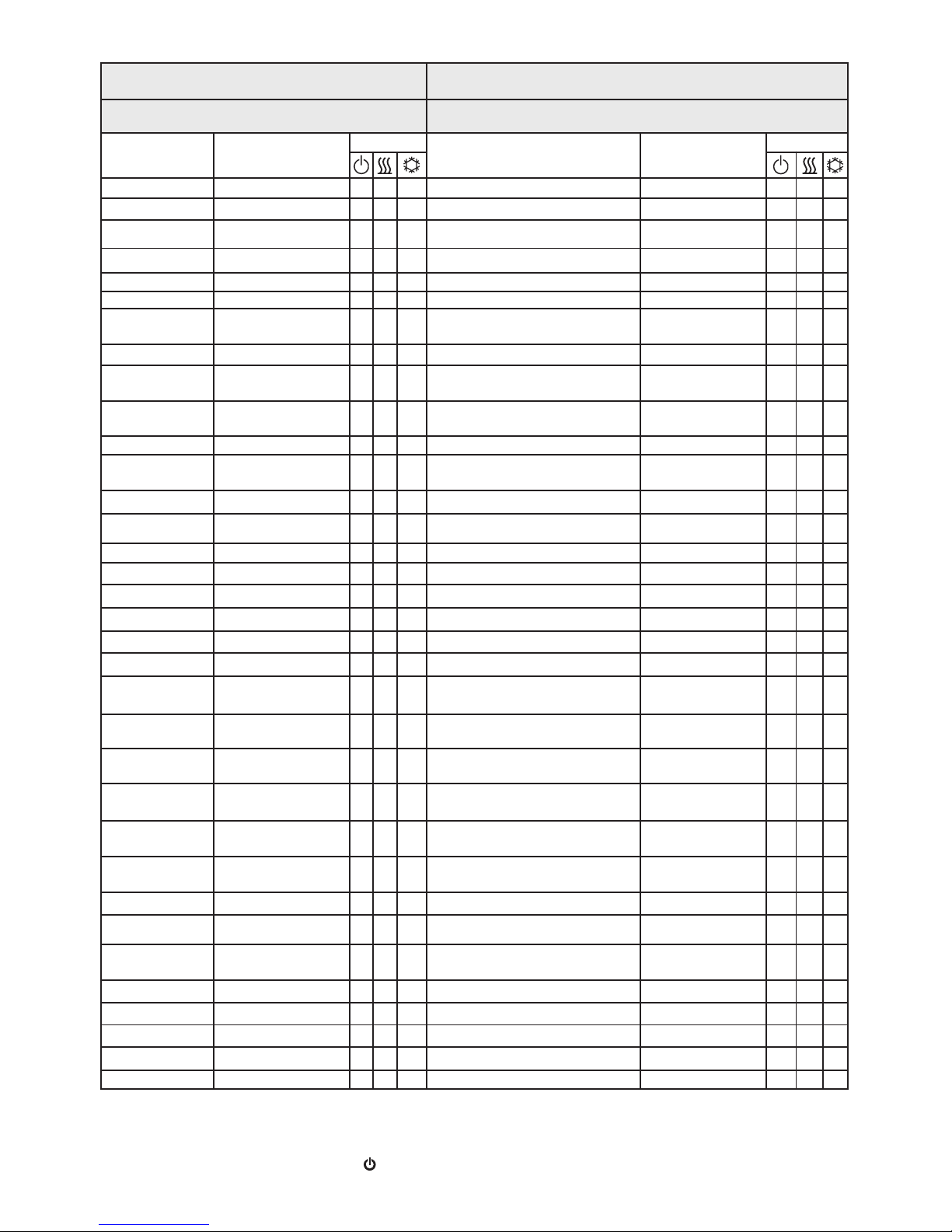
*BL. : Flashing
** In energy saving mode: operation identical to Comfort mode with:
- Setpoint offset by +/-5°C
- LED
: OFF
Comfort Mode**
Frost Protection Mode
Cooling mode Heating mode
Action
Ventilation
(3 speeds)
LED
Action
Ventilation
(low speed
only)
LED
ON OFF OFF No valve Ventilation ON
BL.*
ON OFF
No valve Ventilation ON ON OFF ON
BL.*
OFF OFF
ON OFF OFF
BL.*
OFF OFF
ON OFF OFF No valve Ventilation ON
BL.*
ON OFF
No valve Ventilation ON ON OFF ON
BL.*
OFF OFF
ON OFF OFF Electric heater Ventilation ON
BL.*
ON OFF
ON OFF OFF
Electric heater
as 2nd stage
Ventilation ON
BL.*
ON OFF
No valve Ventilation ON ON OFF ON
BL.*
OFF OFF
ON OFF OFF
Electric heater
as main stage
Ventilation ON
BL.*
ON OFF
ON OFF OFF
Electric heater
as 2nd stage
Ventilation ON
BL.*
ON OFF
No valve Ventilation ON ON OFF ON
BL.*
OFF OFF
ON OFF OFF
Electric heater
as main stage
Ventilation ON
BL.*
ON OFF
ON OFF OFF Electric heater Ventilation ON
BL.*
ON OFF
No valve Ventilation ON ON OFF ON
BL.*
OFF OFF
ON OFF OFF Valve Ventilation ON
BL.*
ON OFF
Valve Ventilation ON ON OFF ON
BL.*
OFF OFF
ON OFF OFF
BL.*
OFF OFF
ON OFF OFF Valve Ventilation ON
BL.*
ON OFF
Valve Ventilation ON ON OFF ON Electric heater Ventilation ON
BL.*
ON OFF
ON OFF OFF Electric heater Ventilation ON
BL.*
ON OFF
ON OFF OFF
Valve + electric
heater as 2nd stage
Ventilation ON
BL.*
ON OFF
Valve Ventilation ON ON OFF ON
Electric heater
as main stage
Ventilation ON
BL.*
ON OFF
ON OFF OFF
Electric heater
as main stage
Ventilation ON
BL.*
ON OFF
ON OFF OFF
Valve + electric heater
as 2nd stage
Ventilation ON
BL.*
ON OFF
Valve Ventilation ON ON OFF ON
Electric heater
as main stage
Ventilation ON
BL.*
ON OFF
ON OFF OFF
Electric heater
as main stage
Ventilation ON
BL.*
ON OFF
ON OFF OFF Electric heater Ventilation ON
BL.*
ON OFF
Cooling valve Ventilation ON ON OFF ON
BL.*
OFF OFF
Cooling valve Ventilation ON ON OFF ON Heating valve Ventilation OFF
BL.*
ON OFF
ON OFF OFF Heating valve Ventilation OFF
BL.*
ON OFF
Cooling valve Ventilation ON ON OFF ON
BL.*
OFF OFF
Cooling valve Ventilation ON ON OFF ON Heating valve Ventilation ON
BL.*
ON OFF
ON OFF OFF Heating valve Ventilation ON
BL.*
ON OFF
Cooling valve Ventilation ON ON OFF ON
BL.*
OFF OFF
Page 10
EN - 9
EN
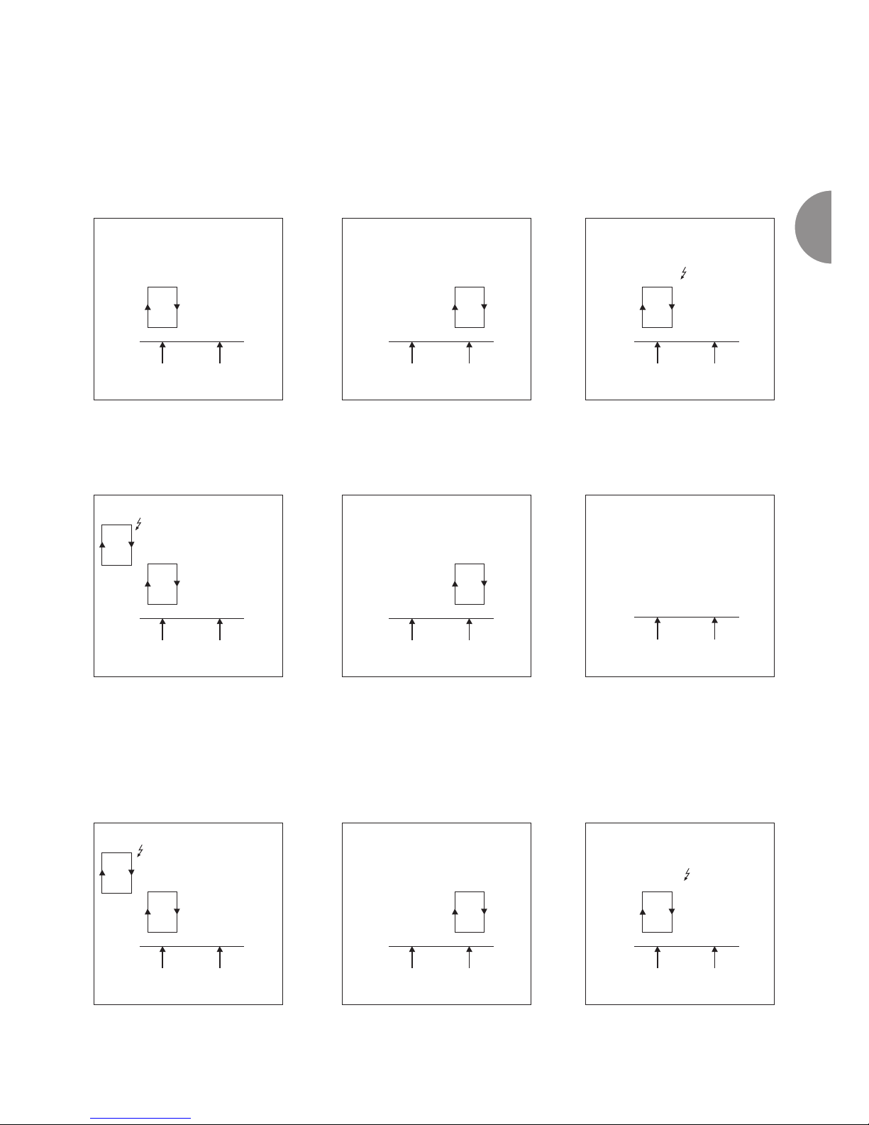
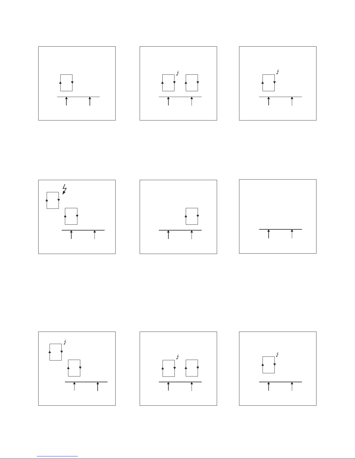
Electric heater management
n The electric heater is managed in time-proportion mode by the thermostat according to the fan speed selected.
n The triggering sequences for the electric heater can be configured as described below.
*Control by air/Application B
Electric stage used as main stage
*Control by Air/Application C
Electric stage used as additional stage
N.B.: this configuration must only be used with hot water with a temperature < 50°C to prevent any risk of the
appliance overheating.
N.B.: this configuration must only be used with hot water with a temperature < 50°C to prevent any risk of the
appliance overheating.
Ventilation Ventilation
Hot water
C F
Water at neutral temperature
C F
Cold water
C F
Ventilation Ventilation
Hot water
C F
Water at neutral temperature
C F
Cold water
C F
Battery, coil
*Control by Air/Application D
Electric stage used as main stage + additional
Ventilation Ventilation
Hot water
C F
Water at neutral temperature
C F
Cold water
C F
Ventilation
+ battery, coil
Battery, coil
Ventilation
+ battery, coil
Page 11
EN - 10
*Control by Water/Application G
Electric stage used as main stage
*Control by Water/Application H
Electric stage used as additional stage
N.B.: this configuration must only be used with hot water with a temperature < 50°C to prevent any risk of the
appliance overheating.
N.B.: this configuration must only be used with hot water with a temperature < 50°C to prevent any risk of the
appliance overheating.
Valve C Valve F
Hot water
C F
Water at neutral temperature
C F
Cold water
C
F
Valve C Valve F
Hot water
C F
Water at neutral temperature
C F
Cold water
C F
Battery, coil
*Control by Water/Application I
Electric stage used as main stage + additional
Valve C Valve F
Hot water
C F
Water at neutral temperature
C F
Cold water
C F
Battery, coil
Battery, coil
Battery, coil
Battery, coil
Battery, coil
Page 12
EN - 11
EN
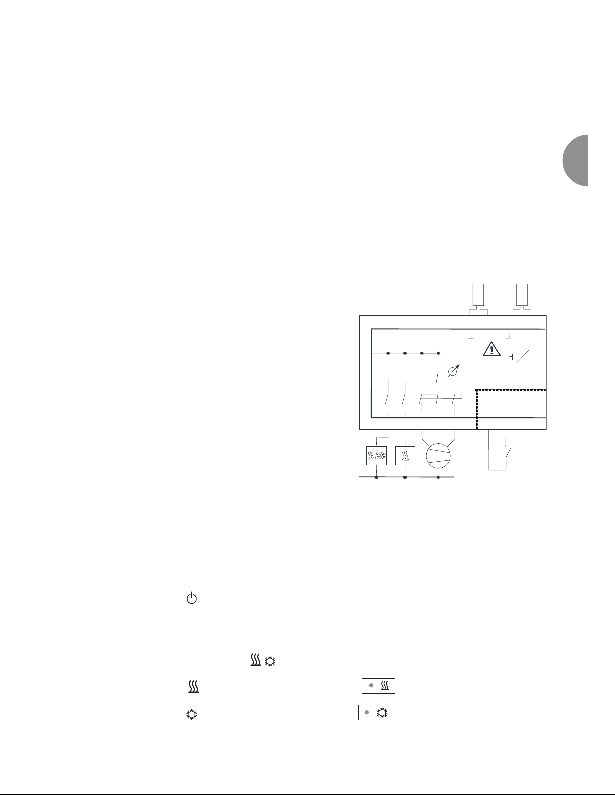
Unit installation
N.B.!
This appliance must be installed in accordance with the connection diagram enclosed with the acknowledgement of
receipt. It must be installed in accordance with accepted engineering standards and must conform with current local
standards. In order to meet Class II requirements, the corresponding installation instructions must be observed.
Mounting:
n In 60 mm flush-mount box; cables pass through the rear
n directly on the wall using the designated holes, passing the cables through the pre-punched holes in
the base in the higher or lower section.
Electrical connection
n Open the unit
n Connect in accordance with the diagram provided, depending on the application. The connection
wires for the regulator, changeover sensor, fan, valves and electric heater have a voltage of 230V~
and must, therefore, be sized accordingly.
n Set the switches for the selected application.
N.B.: The return or changeover sensors must be wired in order to limit the length of the wires and distance them
from the power cables.
The maximum cable length with 1 thermostat and 1
appliance is 10 metres.
Unit connection diagram:
Technical specifications
n Power supply 230/1/50-60 Hz:
*Maximum current on main power supply: 10A
*Valve: 230V - 1A
*Fan: 230V - 3A cosj 0.9
*Electric heater: 230V - 2000W max
*IP30 protection rating, Class II
n Hot comfort setpoint 19°C
n Cold comfort setpoint 23 or 25°C
n Comfort setpoint settings range: +/- 6K
n Hot economy setpoint -5°K
n Cold economy setpoint +5°K
n Hysteresis: 0.5°K
n Post-ventilation 2 mins
LED operation
n LED for active mode
*LED on in Comfort mode
*LED off in Economy or Frost protection mode
*Flashes if the room temperature <8°C
n LED for heating mode and cooling
*The heating LED
comes on when heating is activated
*The cooling LED
comes on when cooling is activated
Alarm
n The 3 LEDS flash: Fault in the air temperature sensors (indoor environment or return).
N
7
6
543
13
14
L
N
III III
V30
DI1
SELV
Xs
2pt
NTC10000
9
230 V
NTC C/O
1110
GND
8
230 V
50/60 Hz
2
1
Page 13
EN - 12
95.01
100
35.1 3629.5 29.5
5
120
38,5 27
27
47.5 47.5
41 27
10
1460
Ø 60
37.6
Tests and warranty
All our appliances are tested before shipping.
CIAT conforms to EC standards, allowing free circulation of its appliances throughout
the European Union. This standard is a guarantee for the safety and protection of
persons.
COM
CO
COM
NTC
Heat shrink sleeve
Disconnectable connector
Disconnectable connector
V30 terminal
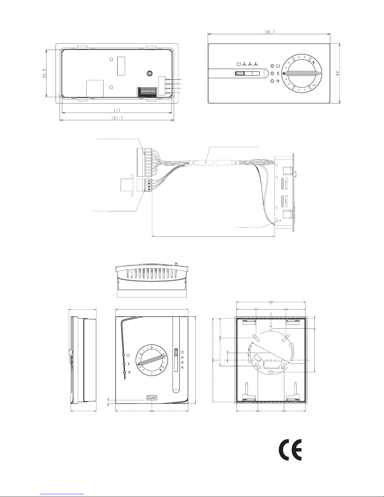
Length of the bundle :
L = 820 Major Line T1 to T3
L = 1120 Major Line T4 to T6
Flush-mounted unit
Wall-mounted unit
Page 14

Siège social
Avenue Jean Falconnier B.P. 14
01350 Culoz - France
Tel. : +33 (0)4 79 42 42 42
Fax : +33 (0)4 79 42 42 10
[email protected] - www.ciat.com
Compagnie Industrielle
d’Applications Thermiques
S.A. au capital de 26 728 480 €
R.C.S. Bourg-en-Bresse B 545.620.114
Non contractual document. With the thought of material improvement
always in mind, CIAT reserves the right,without notice, to proceed with
any technical modification.
CIAT Service
Tel. : 08 11 65 98 98 - Fax : 08 26 10 13 63
(0,15 € / mn)
 Loading...