

CIAT PowerCiat LX ST, PowerCiat LX XE, PowerCiat LX HE Instruction Manual
Instruction manual
06 - 2018
10256
POWERCIAT LX
ST/HE/XE

POWERCIAT LX ST/HE/XE EN-2
CONTENTS
1 - INTRODUCTION .................................................................................................................................................................... 4
1.1 - Installation safety considerations ........................................................................................................................................ 4
1.2 - Equipment and components under pressure ...................................................................................................................... 5
1.3 - Maintenance safety considerations ..................................................................................................................................... 5
1.4 - Repair safety considerations ............................................................................................................................................... 6
2 - PRELIMINARY CHECKS .......................................................................................................................................................8
2.1 - Check equipment received .................................................................................................................................................. 8
2.2 - Moving and siting the unit....................................................................................................................................................8
3 - DIMENSIONS, CLEARANCES ............................................................................................................................................ 10
3.1 - LX 0808 to 1008 ................................................................................................................................................................ 10
3.2 - LX 1108 to 1358 ................................................................................................................................................................10
3.3 - LX 1528 ............................................................................................................................................................................. 11
3.4 - LX1858 to 2308 ................................................................................................................................................................. 11
3.5 - LX2528 to 2628 ................................................................................................................................................................. 12
3.6 - LX 3028 ............................................................................................................................................................................. 12
3.7 - LX 3428 to 4408 ................................................................................................................................................................ 13
3.8 - LX 4608 ............................................................................................................................................................................. 13
3.9 - Multiple chiller installation.................................................................................................................................................. 14
3.10 - Distance to the wall ......................................................................................................................................................... 14
4 - PHYSICAL PROPERTIES AND ELECTRICAL DATA FOR LX UNITS .............................................................................. 15
4.1 - Physical properties of LX units .......................................................................................................................................... 15
4.2 - Electrical data .................................................................................................................................................................... 19
4.3 - Compressor electrical data................................................................................................................................................23
4.4 - Compressor usage per circuit (A, B, C, D) ........................................................................................................................ 23
4.5 - Electrical data, optional hydraulic module ......................................................................................................................... 25
5 - ELECTRICAL CONNECTION .............................................................................................................................................26
5.1 - Power supply ..................................................................................................................................................................... 26
5.2 - Voltage phase imbalance (%)............................................................................................................................................26
5.3 - Power connection/disconnect switch................................................................................................................................. 26
5.4 - Recommended wire sections ............................................................................................................................................ 26
5.5 - Power cable entry..............................................................................................................................................................26
5.6 - Field control wiring ............................................................................................................................................................ 27
6 - APPLICATION DATA ........................................................................................................................................................... 28
6.1 - Operating range ................................................................................................................................................................ 28
6.2 - Minimum chilled water ow (unit without hydraulic module).............................................................................................. 28
6.3 - Maximum chilled water ow (units without hydraulic module) ........................................................................................... 29
6.4 - Variable ow evaporator ....................................................................................................................................................29
6.5 - System minimum water volume ........................................................................................................................................ 29
6.6 - Maximum system water volume ........................................................................................................................................ 29
6.7 - Evaporator water ow rate ................................................................................................................................................ 29
6.8 - Evaporator pressure drop curve ........................................................................................................................................ 30
7 - WATER CONNECTIONS ..................................................................................................................................................... 31
7.1 - Operating precautions ....................................................................................................................................................... 31
7.2 - Victaulic water connections ............................................................................................................................................... 32
7.3 - Flow control ....................................................................................................................................................................... 33
7.4 - Evaporator water box bolt tightening ................................................................................................................................. 33
7.5 - Frost protection .................................................................................................................................................................33
7.6 - Operation of two units in master/slave mode (option) ....................................................................................................... 33
7.7 - Pump characteristics ......................................................................................................................................................... 34
8 - HEAT RECLAIM CONDENSER OPTION ............................................................................................................................37
8.1 - Physical properties, LX units with heat reclaim condenser option .................................................................................... 37
8.2 - Dimensions, clearances .................................................................................................................................................... 37
8.3 - Condenser location ........................................................................................................................................................... 41
8.4 - Condenser water connections ........................................................................................................................................... 41
8.5 - Operating ranges for stable operation (no mode changeover) ......................................................................................... 41
8.6 - Operating limits for changeover between modes ............................................................................................................. 42
8.7 - Flow control ....................................................................................................................................................................... 42
8.8 - Heat reclaim operation ...................................................................................................................................................... 42
8.9 - Condenser pump selection................................................................................................................................................43
8.10 - Frost protection ...............................................................................................................................................................43
EN-3 POWERCIAT LX ST/HE/XE
This manual applies to the following two PowerCiat versions:
• LX ST units, standard efciency
• LX HE units, high seasonal efciency
• LX XE Premium units
For the operation of the control, please refer to the POWERCIAT Connect'Touch control manual.
CONTENTS
9 - FANS WITH AVAILABLE PRESSURE ................................................................................................................................ 43
10 - UNIT OPERATION WITH A FREE COOLING DRYCOOLER ........................................................................................... 43
10.1 - Unit operation option with a free cooling drycooler ......................................................................................................... 43
11 - MAJOR SYSTEM COMPONENTS AND OPERATION DATA ...........................................................................................45
11.1 - Direct-drive twin-screw compressor with variable capacity slide valve ...........................................................................45
11.2 - Pressure vessels .............................................................................................................................................................45
11.3 - High-pressure safety switch ............................................................................................................................................46
11.4 - Condensers .....................................................................................................................................................................46
11.5 - Fans .................................................................................................................................................................................46
11.6 - Electronic expansion valve (EXV) ...................................................................................................................................47
11.7 - Moisture indicator ............................................................................................................................................................47
11.8 - Filter drier ........................................................................................................................................................................47
11.9 - Sensors ...........................................................................................................................................................................47
11.10 - Service valve set (option) ..............................................................................................................................................47
11.11 - Power factor correction capacitors (option) ................................................................................................................... 47
12 - MAIN OPTIONS ................................................................................................................................................................. 49
13 - STANDARD MAINTENANCE ............................................................................................................................................51
13.1 - Level 1 maintenance ....................................................................................................................................................... 51
13.2 - Level 2 maintenance ....................................................................................................................................................... 51
13.3 - Level 3 (or higher) maintenance......................................................................................................................................51
13.4 - Tightening torques for the main electrical connections ...................................................................................................51
13.5 - Tightening torques for the main bolts and screws ...........................................................................................................52
13.6 - Condenser coil ................................................................................................................................................................52
13.7 - Evaporator maintenance ................................................................................................................................................. 53
13.8 - Compressor maintenance ............................................................................................................................................... 53
13.9 - Precaution for compressor power supply bus bar connection......................................................................................... 54
13.10 - Check of power factor correction capacitors ................................................................................................................. 54
14 - START-UP CHECKLIST FOR LX LIQUID CHILLERS
(USE FOR JOB FILE) ........................................................................................................................................................55

POWERCIAT LX ST/HE/XE EN-4
1 - INTRODUCTION
PowerCiatTM LX ST/HE/XE units are designed to cool water for
the air conditioning of buildings or for industrial processes.
Prior to the initial start-up of LX units, the persons responsible
for the on-site installation, start-up, operation, and maintenance
of this unit should be thoroughly familiar with these instructions
and the technical characteristics for the project, specic to the
installation site.
They are designed for an operating life of 15 years by assuming
a 57 % utilisation factor; that is approximately 75,000 operating
hours.
LX liquid chillers are designed to provide a very high level of
safety during installation, start-up, operation and maintenance.
They will provide safe and reliable service when operated within
their application range.
This manual provides the necessary information to familiarize
yourself with the control system before performing start-up
procedures. The procedures in this manual are arranged in the
sequence required for machine installation, start-up, operation
and maintenance.
Always ensure that all required safety measures are followed,
including those in this document, such as, wearing protective
clothing (gloves, ear defenders, safety glasses and shoes), using
appropriate tools, employing qualied and skilled technicians
(electricians, refrigeration engineers) and following local
regulations.
To nd out, if these products comply with European directives
(machine safety, low voltage, electromagnetic compatibility,
equipment under pressure etc.) check the declarations of
conformity for these products.
1.1 - Installation safety considerations
Access to the unit must be reserved to authorised personnel,
qualied and trained in monitoring and maintenance. The access
limitation device must be installed by the customer (e.g. cut-off,
enclosure).
After the unit has been received, when it is ready to be installed
or reinstalled, and before it is started up, it must be inspected for
damage. Check that the refrigerant circuit(s) is (are) intact,
especially that no components or pipes have shifted (e.g. following
a shock). If in doubt, carry out a leak tightness check and verify
with the manufacturer that the circuit integrity has not been
impaired. If damage is detected upon receipt, immediately le a
claim with the shipping company.
CIAT strongly recommends employing a specialised
company to unload the machine.
Do not remove the skid or the packaging until the unit is in
its nal position. These units can be moved with a fork lift
truck, as long as the forks are positioned in the right place
and direction on the unit.
The units can also be lifted with slings, using only the
designated lifting points marked on the unit.
These units are not designed to be lifted from above. Use
slings with the correct capacity, and always follow the lifting
instructions on the certied drawings supplied with the unit.
Safety is only guaranteed, if these instructions are carefully
followed. If this is not the case, there is a risk of material
deterioration and injuries to personnel.
DO NOT COVER ANY PROTECTION DEVICES.
This applies to fuse plugs and relief valves (if used) in the
refrigerant or heat transfer medium circuits. Check if the
original protection plugs are still present at the valve outlets.
These plugs are generally made of plastic and should not
be used. If they are still present, please remove them. Install
devices at the valve outlets or drain piping that prevent the
penetration of foreign bodies (dust, building debris, etc.)
and atmospheric agents (water can form rust or ice). These
devices, as well as the drain piping, must not impair
operation and not lead to a pressure drop that is higher than
10% of the control pressure.
Classication and control
In accordance with the Pressure Equipment Directive and
national usage monitoring regulations in the European
Union the protection devices for these machines are
classied as follows:
Safety
accessory
(1)
Damage limitation accessory
in case of an external re
(2)
Refrigerant Side
High pressure switch x
External relief valve
(3)
x
Heat transfer uid side
External relief valve
(4) (4)
(1) Classied for protection in normal service situations.
(2) Classied for protection in abnormal service situations. These accessories
are sized for res with a thermal ow of 10kW/m². No combustible matter
should be placed within 6.5m of the unit.
(3) The instantaneous overpressure limitation of 10% of the operating pressure
does not apply to this abnormal service situation.
The control pressure can be higher than the service pressure. In this case,
either the design temperature or the high pressure switch ensures that the
service pressure is not exceeded in normal service situations.
(4) The selection of these relief valves must be made by the personnel responsible
for completing the hydraulic installation.
Do not remove these valves and fuses, even if the re risk
is under control for a particular installation. There is no
guarantee that the accessories are re-installed if the
installation is changed or for transport with a gas charge.
When the unit is subjected to re, safety devices prevent
rupture due to over-pressure by releasing the refrigerant.
The uid may then be decomposed into toxic residues when
subjected to the ame:
• Stay away from the unit.
• Set up warnings and recommendations for personnel in
charge to stop the re.
• Fire extinguishers appropriate to the system and the
refrigerant type must be easily accessible
All factory-installed relief valves are lead-sealed to prevent
any calibration change. If the relief valves are installed on
a change-over valve, this is equipped with a relief valve on
each of the two outlets. Only one of the two relief valves is
in operation, the other one is isolated. Never leave the
change-over valve in the intermediate position, i.e. with both
ways open (Bring the actuator in abutment, front or back
according to the outlet to isolate).
If a relief valve is removed for checking or replacement
please ensure that there is always an active relief valve on
each of the change-over valves installed in the unit.
The external relief valves must always be connected to drain
pipes for units installed in a closed room. Refer to the
installation regulations, for example those of European
standard EN 378 and EN 13136.
EN-5 POWERCIAT LX ST/HE/XE
These pipes must be installed in a way that ensures that
people and property are not exposed to refrigerant leaks.
As the uids can be diffused in the air, ensure that the outlet
is far away from any building air intake, or that they are
discharged in a quantity that is appropriate for a suitably
absorbing environment.
Periodic check of the relief valves: See chapter 1.3
“Maintenance safety considerations”.
Provide a drain in the drain pipe, close to each relief valve,
to avoid an accumulation of condensate or rain water.
All precautions concerning handling of refrigerant must be
observed in accordance with local regulations.
Ensure good ventilation, as accumulation of refrigerant in
an enclosed space can displace oxygen and cause
asphyxiation or explosions.
Inhalation of high concentrations of vapour is harmful and
may cause heart irregularities, unconsciousness, or death.
Vapour is heavier than air and reduces the amount of oxygen
available for breathing. These products cause eye and skin
irritation. Decomposition products are hazardous.
1.2 - Equipment and components under
pressure
These products incorporate pressure equipment or components.
We recommend that you consult your appropriate national trade
association or the owner of the equipment or components under
pressure (declaration, re-qualification, retesting, etc.).
The characteristics of this equipment/these components are
given on the nameplate or in the required documentation,
supplied with the products.
These units are intended to be stored and operated in an
environment where the ambient temperature must be not less
than the lowest allowable temperature indicated on the
nameplate.
Do not introduce signicant static or dynamic pressure with
regard to the operating pressures used during operation or for
tests in the refrigerant circuit or in the heat exchange circuits.
See section 11.2 - “Pressure vessels”.
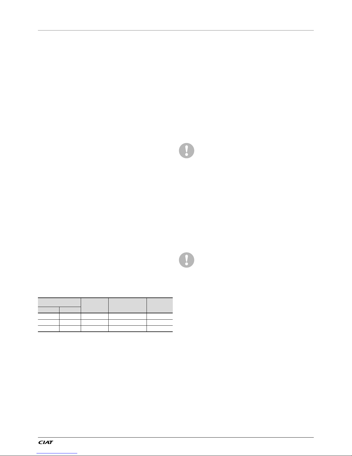
1.3 - Maintenance safety considerations
CIAT recommends using the following maintenance logbook
template (the table below should not be considered a reference,
nor does it invoke the manufacturer's liability):
Intervention
Name of the
commissioning
engineer
Applicable national
regulations
Verication
Organism
Date Nature
(1)
(1) Maintenance, repairs, regular verications (EN 378), leakage, etc.
Engineers working on the electric or refrigeration components
must be authorized, trained and fully qualied to do so.
All refrigerant circuit repairs must be carried out by a trained
person, fully qualied to work on these units. He must have been
trained and be familiar with the equipment and the installation.
All welding operations must be carried out by qualied specialists.
Any manipulation (opening or closing) of a shut-off valve must
be carried out by a qualied and authorised engineer. These
procedures must be carried out with the unit shut-down.
NOTE: The unit must never be left shut down with the liquid
line valve closed, as liquid refrigerant can be trapped
between this valve and the expansion device and lead to
the risk of a pressure increase. This valve is situated on the
liquid line before the lter drier box.
During any handling, maintenance and service operations
the engineers working on the unit must be equipped with
safety gloves, glasses, shoes and protective clothing.
Never work on a unit that is still energized.
Never work on any of the electrical components, until the
general power supply to the unit has been cut using the
disconnect switch(es) in the control box(es).
If any maintenance operations are carried out on the unit,
lock the power supply circuit in the open position ahead of
the machine.
If the work is interrupted, always ensure that all circuits are
still deenergised before resuming the work.
Even if the unit has been switched off, the power
circuit remains energized, unless the unit or circuit
disconnect switch is open. Refer to the wiring
diagram for further details. Attach appropriate safety
labels.
Units with the Power Factor Correction option are equipped
with capacitor batteries with a discharge time of ve (5)
minutes after disconnecting the power. After disconnecting
the power to the control box, wait ve minutes before
opening the control box. Before any intervention, verify that
there is no voltage present at any accessible conducting
parts of the power circuit.
OPERATING CHECKS:
Important information regarding the refrigerant used:
This product contains uorinated greenhouse gas covered
by the Kyoto protocol.
Fluid type: R134a
Global Warming Potential (GWP): 1430
1. Any intervention on the refrigerant circuit of this
product should be performed in accordance with
the applicable legislation. In the EU,
the regulation is called F-Gas, N°517/2014
2. Ensure that the refrigerant is never released to
the atmosphere during installation, maintenance
or equipment disposal.
3. The deliberate gas release into the atmosphere
is not allowed.
4. If a refrigerant leak is detected, ensure that it is
stopped and repaired as quickly as possible.
5. Only qualified and certified personnel can
perform installation and maintenance work, run
the refrigerant circuit leak tests, prepare the
equipment for disposal, and recover the
refrigerant.
6. The gas recovery for recycling, regeneration or
destruction is at customer charge.
7. Periodic leak tests have to be carried out by the
customer or by third parties. The EU regulation
set the periodicity here after:
1 - INTRODUCTION
POWERCIAT LX ST/HE/XE EN-6
System WITHOUT
leakage detection
No Check 12 Months 6 Months 3 Months
System WITH leakage
detection
No Check 24 Months 12 Months 6 Months
Refrigerant
charge/circuit
(CO
2
equivalent)
< 5 Tons
5 ≤ Charge
< 50 Tons
50 ≤ Charge
< 500 Tons
Charge
> 500 Tons*
Refrigerant charge/
Circuit (kg)
R134A
(GWP 1430)
Charge
< 3.5 kg
3.5 ≤ Charge
< 34.9 kg
34.9 ≤ Charge
< 349.7 kg
Charge
> 349.7 kg
R407C
(GWP 1774)
Charge
< 2.8 kg
2.8 ≤ Charge
< 28.2 kg
28.2 ≤ Charge
< 281.9 kg
Charge
> 281.9 kg
R410A
(GWP 2088)
Charge
< 2.4 kg
2.4 ≤ Charge
< 23.9 kg
23.9 ≤ Charge
< 239.5 kg
Charge
> 239.5 kg
HFO’s:
R1234ze
No requirement
* From 01/01/2017, units must be equipped with a leak detection system.
8. A logbook must be maintained for equipment
subject to periodic leak tests. It should contain
the quantity and the type of uid present in the
installation (added and recovered), the quantity
of recycled uid, the date and result of the leak
test, the name of the operator and the name of
his/her company, etc.
9. Contact your local dealer or installer if you have any
questions.
The information on operating inspections given in annex C
of standard EN 378 can be used if no similar criteria exist
in the national regulations.
While working in the fan area, especially when grilles or
casings are removed, disconnect the fan power supply to
prevent their automatic restart.
PROTECTION DEVICE CHECKS:
If no national regulations exist, check the protection devices
on site in accordance with standard EN 378: Once a year for
the high-pressure switches, every ve years for external
relief valves.
The company or organisation that conducts a pressure switch
test must establish and implement detailed procedures for:
- Safety measures
- Measuring equipment calibration
- Validating operation of protective devices
- Test protocols
- Recommissioning of the equipment.
Consult CIAT Service for this type of test. In this document, CIAT
only outlines the principle for a test without removal of the
pressure switches:
- Check and record the nominal values for triggering the
pressure switches and external relief devices (valves,
if present).
- Be ready to switch-off the main disconnect switch of the
power supply if the pressure switch does not trigger (avoid
over-pressure or excess gas in case of valves on the
high-pressure side with the recovery condensers)
- Connect a pressure gauge protected against pulsations
(filled with oil with maximum pointer if mechanical),
preferably calibrated (the values displayed on the user
interface may be inaccurate in an instant reading because
of the scanning delay applied in the control)
- Complete an HP Test as provided by the software (refer to
the Control IOM for details).
If the machine operates in a corrosive environment, inspect
the protection devices more frequently.
Regularly carry out leak tests and immediately repair any
leaks. Ensure regularly that the vibration levels remain
acceptable and close to those at the initial unit start-up.
Before opening a refrigerant circuit, purge and consult the
pressure gauges.
Change the refrigerant after an equipment failure, following
a procedure such as the one described in NF E29-795 or
carry out a refrigerant analysis in a specialist laboratory.
If the refrigerant circuit is opened for a day or less, block all
openings; ll the circuit with a nitrogen charge if open for
longer periods.
1.4 - Repair safety considerations
All installation parts must be maintained by the personnel in charge,
in order to avoid material deterioration and injuries to people. Faults
and leaks must be repaired immediately. The authorized technician
must have the responsibility to repair the fault immediately. After
each repair of the unit, check the operation of the protection devices
and create a report of the parameter operation at 100%.
Comply with the regulations and recommendations in unit and HVAC
installation safety standards, such as: EN 378, ISO 5149, etc.
If a leak occurs or if the refrigerant becomes contaminated
(e.g. by a short circuit in a motor) remove the complete charge
using a recovery unit and store the refrigerant in mobile
containers.
Repair the leak detected and recharge the circuit with the total
R-134a charge, as indicated on the unit name plate. Certain parts
of the circuit can be isolated. Only charge liquid refrigerant
R-134a at the liquid line.
Ensure that you are using the correct refrigerant type before
recharging the unit. Charging any refrigerant other than the
original charge type (R-134a) will impair machine operation
and even destroy the compressors. The compressors
operating with this refrigerant type are lubricated with a
synthetic polyolester oil.
RISK OF EXPLOSION:
Never use air or a gas containing oxygen during leak tests
to purge lines or to pressurise a machine. Pressurised air
mixtures or gases containing oxygen can be the cause of
an explosion.
Only use dry nitrogen for leak tests, possibly with an appropriate
tracer gas.
If the recommendations above are not observed, this can have
serious or even fatal consequences and damage the installation.
Never exceed the specied maximum operating pressures.
Verify the allowable maximum high- and low-side test
pressures by checking the instructions in this manual and
the pressures given on the unit name plate.
1 - INTRODUCTION
EN-7 POWERCIAT LX ST/HE/XE
Do not unweld or amecut the refrigerant lines or any
refrigerant circuit component until all refrigerant (liquid and
vapour) as well as the oil have been removed from chiller.
Traces of vapour should be displaced with dry air nitrogen.
Refrigerant in contact with an open ame produces toxic
gases.
The necessary protection equipment must be available, and
appropriate fire extinguishers for the system and the
refrigerant type used must be within easy reach.
Do not siphon refrigerant.
Avoid spilling liquid refrigerant on skin or splashing it into
the eyes. Use safety goggles and safety gloves. Wash any
spills from the skin with soap and water. If liquid refrigerant
enters the eyes, immediately and abundantly ush the eyes
with water and consult a doctor.
The accidental releases of the refrigerant, due to small leaks
or signicant discharges following the rupture of a pipe or
an unexpected release from a safety valve, can cause
frostbites and burns to personnel exposed. Do not ignore
such injuries. Installers, owners and especially service
engineers for these units must:
• Seek medical attention before treating such injuries.
• Have access to a rst-aid kit, especially for treating eye
injuries.
We recommend to apply standard EN 378-3 Annex 3.
Never apply an open ame or live steam to a refrigerant
container. Dangerous overpressure can result. If it is
necessary to heat refrigerant, use only warm water.
During refrigerant removal and storage operations follow applicable
regulations. These regulations, permitting conditioning and recovery
of halogenated hydrocarbons under optimum quality conditions for
the products and optimum safety conditions for people, property
and the environment are described in standard NF E29-795.
Any refrigerant transfer and recovery operations must be carried
out using a transfer unit. A 3/8” SAE connector on the manual
liquid line valve is supplied with all units for connection to the
transfer station. The units must never be modied to add refrigerant
and oil charging, removal and purging devices. All these devices
are provided with the units. Please refer to the certied dimensional
drawings for the units.
Do not re-use disposable (non-returnable) cylinders or
attempt to rell them. It is dangerous and illegal. When
cylinders are empty, evacuate the remaining gas pressure,
and move the cylinders to a place designated for their
recovery. Do not incinerate them.
Only use R134a refrigerant, in accordance with AHRI
Standard 700 (published by the US Air conditioning,
Heating and Refrigeration Institute). The use of any
other refrigerant may expose users and operators
to unexpected risks.
Do not attempt to remove refrigerant circuit components or
ttings, while the machine is under pressure or while it is
running. Be sure pressure is at 0 kPa and that the unit has
been shut-down and de-energised before removing
components or opening a circuit.
Do not attempt to repair or recondition any safety devices
when corrosion or build-up of foreign material (rust, dirt,
scale, etc.) is found within the valve body or mechanism.
If necessary, replace the device. Do not install relief valves
in series or backwards.
No part of the unit must be used as a walkway, rack
or support. Periodically check and repair or if
necessary replace any component or piping that
shows signs of damage.
The refrigerant lines can break under the weight and release
refrigerant, causing personal injury.
Do not climb on a machine. Use a platform, or staging to
work at higher levels.
Use mechanical lifting equipment (crane, hoist, winch, etc.)
to lift or move heavy components. For lighter components,
use lifting equipment when there is a risk of slipping or losing
your balance.
Use only original replacement parts for any repair or
component replacement. Consult the list of replacement
parts that corresponds to the specication of the original
equipment.
Do not drain water circuits containing industrial brines,
without informing the technical service department at the
installation site or a competent body rst.
Close the entering and leaving water shutoff valves and
purge the unit water circuit, before working on the
components installed on the circuit (screen lter, pump,
water ow switch, etc.).
Do not loosen the water box bolts until the water boxes have
been completely drained.
Periodically inspect all valves, ttings and pipes of the
refrigerant and hydraulic circuits to ensure that they do not
show any corrosion or any signs of leaks.
It is recommended to wear ear defenders, when working
near the unit and the unit is in operation.
1 - INTRODUCTION
POWERCIAT LX ST/HE/XE EN-8
2 - PRELIMINARY CHECKS
2.1 - Checking the equipment received
• Check that the unit has not been damaged during transport
and that no parts are missing. If the unit has been damaged
or the shipment is incomplete, send a claim to the shipping
company.
• Compare the name plate data with the order. The name plate is
attached in two places to the unit:
- On one of the unit sides on the outside,
- On the control box door on the inside.
• The unit name plate must include the following information:
- Version number
- Model number
- CE marking
- Serial number
- Year of manufacture and test date
- Fluid being transported
- Refrigerant used and refrigerant class
- Refrigerant charge per circuit
- Containment uid to be used
- PS: Min./max. allowable pressure (high and low pressure
side)
- TS: Min./max. allowable temperature (high and low pressure
side)
- Pressure switch cut-out pressure
- Unit leak test pressure
- Voltage, frequency, number of phases
- Maximum current drawn
- Maximum power input
- Unit net weight
• Conrm that all accessories ordered for on-site installation have
been supplied, are complete and undamaged.
The unit must be checked periodically during its whole
operating life to ensure that no shocks (handling accessories,
tools etc.) have damaged it. If necessary, damaged parts
must be repaired or replaced. See also chapter 13 “Standard
maintenance”.
2.2 - Handling and positioning the unit
2.2.1 - Handling
See chapter 1.1 “Installation safety considerations”.
In some cases vertical supports are added for the transport and
handling of the unit. These supports can be removed for access
or connection, if required.
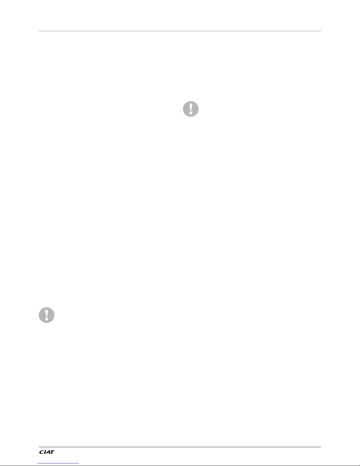
IMPORTANT: Follow the disassembly sequence shown in
the disassembly instructions.
NOTE:
• Unbolt item: 1
• Loosen screw item: 2
• Raise and remove frame post item: 3
• Screw off item: 4 and remove reinforcement plate item: 5
Keep the vertical supports after commissioning the units and
re-insert them when the unit is moved.
EN-9 POWERCIAT LX ST/HE/XE
2.2.2 - Positioning the unit
The machine must be installed in a place that is not accessible to the
public or protected against access by non-authorised persons.
In case of extra-high units the machine environment must
permit easy access for maintenance operations.
Always refer to the chapter 3 “Dimensions, clearances” to conrm
that there is adequate space for all connections and service
operations. For the centre of gravity coordinates, the position of the
unit mounting holes, and the weight distribution points, refer to the
certied dimensional drawing supplied with the unit.
The support points under the chassis must have at least the size
of the chassis opening at the lifting point (minimum 220 x 180 mm)
in order to prevent a deformation of the chassis.
These units are typically used in refrigeration systems,
and therefore do not need to be able to withstand earthquakes
or high winds. Earthquake resistance has not been veried.
Only use slings at the designated lifting points
which are marked on the unit.
Before siting the unit check that:
- The permitted loading at the site is adequate or that
appropriate strengthening measures have been taken.
- The unit is installed level on an even surface (maximum
tolerance is 5 mm in both axes).
- There is adequate space above the unit for air ow and to
ensure access to the components.
- The number of support points is adequate and that they are
in the right places.
- The location is not subject to ooding.
- For outdoor installations, where heavy snowfall is likely and
long periods of sub-zero temperatures are normal, provision
has to be made to prevent snow accumulating by raising
the unit above the height of drifts normally experienced.
- Bafes may be necessary to deect strong winds. They
must not restrict air ow into the unit.
Before lifting the unit, check that all casing panels
are securely xed in place. Lift and set down the
unit with great care. Tilting and jarring can damage
the unit and impair unit operation.
If units are hoisted with rigging, it is advisable to protect the coils
against accidental impacts. Use struts or spreader bar to spread
the slings above the unit. Do not tilt a unit more than 15°.
WARNING: Never push or lever on any of the enclosure
panels of the unit. Only the base of the unit frame is designed
to withstand such stresses.
If a unit contains a hydraulic module, the hydraulic module
and pump piping must be installed in a way that does not
submit it to any strain. The hydraulic module pipes must be
tted so that the pump does not support the weight of the
pipes.
2.2.3 - Checks before system start-up
Before the start-up of the refrigeration system, the complete
installation, including the refrigeration system must be veried
against the installation drawings, dimensional drawings, system
piping and instrumentation diagrams and the wiring diagrams.
For these checks national regulations must be followed. If the
national regulation does not specify any details, refer to standard
EN 378 as follows:
External visual installation checks:
- Ensure that the machine is charged with refrigerant. Verify
on the unit nameplate that the ‘fluid transported’ is R134A
and is not nitrogen.
- Compare the complete installation with the refrigeration
system and power circuit diagrams.
- Check that all components comply with the design
specifications.
- Check that all protection documents and equipment
provided by the manufacturer (dimensional drawings, P&ID,
declarations etc.) to comply with the regulations are present.
- Verify that the environmental safety and protection and
devices and arrangements provided by the manufacturer
to comply with the regulations are in place.
- Verify that all documents for pressure containers,
certificates, name plates, files, instruction manuals provided
by the manufacturer to comply with the regulations are
present.
- Verify the free passage of access and safety routes.
- Check that ventilation in the plant room is adequate.
- Check that refrigerant detectors are present.
- Verify the instructions and directives to prevent the
deliberate removal of refrigerant gases that are harmful to
the environment.
- Verify the installation of connections.
- Verify the supports and fixing elements (materials, routing
and connection).
- Verify the quality of welds and other joints.
- Check the protection against mechanical damage.
- Check the protection against heat.
- Check the protection of moving parts.
- Verify the accessibility for maintenance or repair and to
check the piping.
- Verify the status of the valves.
- Verify the quality of the thermal insulation and of the vapour
barriers.
2 - PRELIMINARY CHECKS
POWERCIAT LX ST/HE/XE EN-10
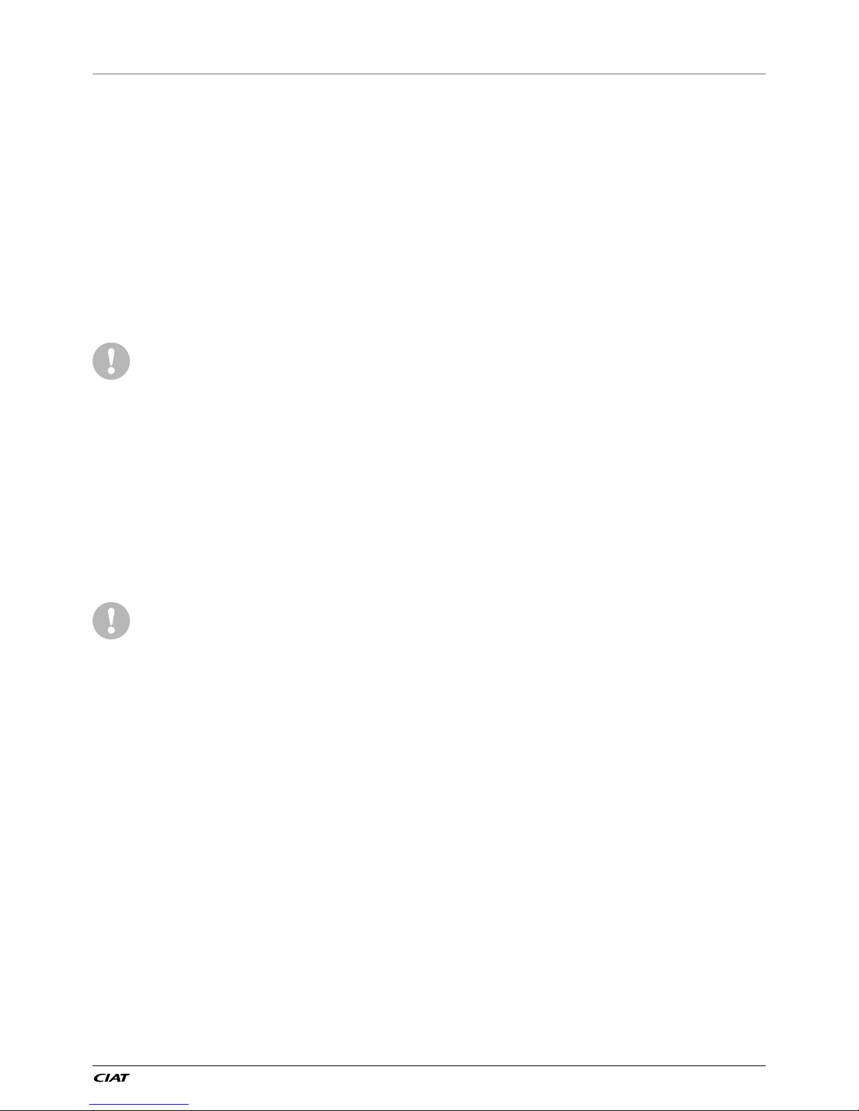
3 - DIMENSIONS/CLEARANCES
3.1 - LX 0808 to 1008
1
2
1
1
Power And control
electrical box
2297 HT
3604 HT
2253 HT
1500
1500
2200
1500
500
1
3.2 - LX 1108 to 1358
Power And control
electrical box
2297 HT
4798 HT
2253 HT
1500
500
2200
1500
1500
1
1
2
1
1
Key
NOTES:
• Drawings are not contractually binding.
• Before designing an installation, consult the certied
dimensional drawings, available on request.
• For the positioning of the xing points, weight distribution
and centre of gravity coordinates please refer to the
dimensional drawings.
• If the installation includes several units or if this (these)
is (are) close to walls, please refer to chapters 3.12
“Multiple chiller installation” and 3.13 “Distance to the
wall” of this document to determine the space required.
All dimensions are given in mm.
a
Required clearances for maintenance (see note)
b
Recommended space for evaporator tube removal
Water inlet for standard unit
For the Brine and evaporator options with one pass less or one pass
more, refer to the certied dimensional drawing.
Water outlet for standard unit
For the
Brine and evaporator options with one pass less or one pass
more
, refer to the certied dimensional drawing.
Air outlet – do not obstruct
Power supply and control connection
EN-11 POWERCIAT LX ST/HE/XE
3 - DIMENSIONS, CLEARANCES
3.3 - LX 1528
2
1
1
1
1
Power And control
Electrical
box
1500
2200
1500
1500
2253 HT
5992 Ht
2297 HT
3.4 - LX1858 to 2308
Power electrical Box
1500
2200
1500
1500
2253 HT
7186 Ht
2297 HT
2
1
1
1
1
Key
NOTES:
• Drawings are not contractually binding.
• Before designing an installation, consult the certied
dimensional drawings, available on request.
• For the positioning of the xing points, weight distribution
and centre of gravity coordinates please refer to the
dimensional drawings.
• If the installation includes several units or if this (these)
is (are) close to walls, please refer to chapters 3.12
“Multiple chiller installation” and 3.13 “Distance to the
wall” of this document to determine the space required.
All dimensions are given in mm.
a
Required clearances for maintenance (see note)
b
Recommended space for evaporator tube removal
Water inlet for standard unit
For the Brine and evaporator options with one pass less or one pass
more, refer to the certied dimensional drawing.
Water outlet for standard unit
For the
Brine and evaporator options with one pass less or one pass
more
, refer to the certied dimensional drawing.
Air outlet – do not obstruct
Power supply and control connection
POWERCIAT LX ST/HE/XE EN-12
3.5 - LX2528 to 2628
Power And control electrical box
8380 HT
2253 HT
1500
1500
1500
2200
2297 HT
1
1
1
2
1
3.6 - LX 3028
Power And control electrical box
9574 HT
2253 HT
1500
1500
1500
2200
2297 HT
1
1
1
2
1
Key
NOTES:
• Drawings are not contractually binding.
• Before designing an installation, consult the certied
dimensional drawings, available on request.
• For the positioning of the xing points, weight distribution
and centre of gravity coordinates please refer to the
dimensional drawings.
• If the installation includes several units or if this (these)
is (are) close to walls, please refer to chapters 3.12
“Multiple chiller installation” and 3.13 “Distance to the
wall” of this document to determine the space required.
All dimensions are given in mm.
a
Required clearances for maintenance (see note)
b
Recommended space for evaporator tube removal
Water inlet for standard unit
For the Brine and evaporator options with one pass less or one pass
more, refer to the certied dimensional drawing.
Water outlet for standard unit
For the
Brine and evaporator options with one pass less or one pass
more
, refer to the certied dimensional drawing.
Air outlet – do not obstruct
Power supply and control connection
3 - DIMENSIONS, CLEARANCES
EN-13 POWERCIAT LX ST/HE/XE
3.7 - LX 3428 to 4408
2253 HT
419
467
2297 HT
11 962
1500
1500
1500
2200
Power and control
electrical box
2
1
1
1
1
3.8 - LX 4608
2253 HT
419
467
2297 HT
13156 HT
1500
1500
1500
2200
Power And control electrical box
1
2
1
1
1
Key
NOTES:
• Drawings are not contractually binding.
• Before designing an installation, consult the certied
dimensional drawings, available on request.
• For the positioning of the fixing points, weight
distribution and centre of gravity coordinates please
refer to the dimensional drawings.
• If the installation includes several units or if this (these)
is (are) close to walls, please refer to chapters 3.12
“Multiple chiller installation” and 3.13 “Distance to the
wall” of this document to determine the space required.
All dimensions are given in mm.
a
Required clearances for maintenance (see note)
b
Recommended space for evaporator tube removal
Water inlet for standard unit
For the Brine and evaporator options with one pass less or one pass
more, refer to the certied dimensional drawing.
Water outlet for standard unit
For the
Brine and evaporator options with one pass less or one pass
more
, refer to the certied dimensional drawing.
Air outlet – do not obstruct
Power supply and control connection
3 - DIMENSIONS, CLEARANCES
POWERCIAT LX ST/HE/XE EN-14
3.9 - Installation of multiple chillers
It is recommended to install multiple chillers in a single row,
arranged as shown in the example below, to avoid recycling of
warm air from one unit to another.
1.5 m
min.
1.5 m
min.
If the situation at the site does not permit this arrangement, contact
your distributor to evaluate the various possible arrangements.
In certain situations an accessory (supplied loose at the time of
purchase) can be added.
3.10 - Distance from the wall
To ensure correct operation for most cases:
If h < H (2.3 m), minimum S = 3 m
If h > H or S < 3 m, contact your CIAT distributor to evaluate the
various possible arrangements. In certain situations an accessory
(supplied loose at the time of purchase) can be added.
H
S
h
Anti-vibration mounts
3 - DIMENSIONS, CLEARANCES
EN-15 POWERCIAT LX ST/HE/XE
4 - PHYSICAL PROPERTIES AND ELECTRICAL DATA FOR LX UNITS
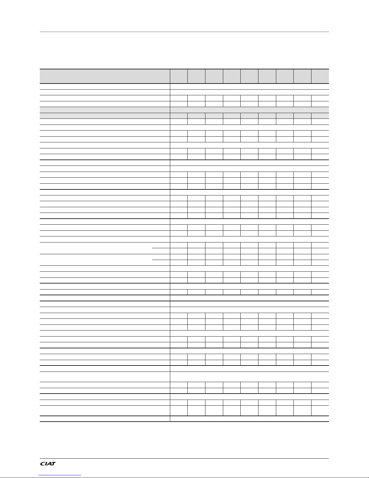
4.1 - Physical properties of LX units
LX 0808 to 2158 units
LX ST-HE 0808 0908 1008 1108 1358 1528 1858 2008 2158
Sound levels
LX ST HE
Sound power
(1)
dB(A) 100 100 100 100 102 100 102 100 103
Sound pressure at 10 m
(2)
dB(A) 68 68 68 68 70 68 69 68 71
LX ST HE + low noise option
Sound power
(1)
dB(A) 94 94 95 96 96 96 98 96 98
Sound pressure at 10 m
(2)
dB(A) 62 62 63 64 64 64 66 63 65
LX ST HE + Xtra low noise option
Sound power
(1)
dB(A) 87 87 87 90 91 91 93 92 93
Sound pressure at 10 m
(2)
dB(A) 55 55 55 58 59 59 60 59 60
LX ST HE + Super low noise option
Sound power
(1)
dB(A) - - - - 89 89 91 90 91
Sound pressure at 10 m
(2)
dB(A) - - - - 57 56 58 57 59
Dimensions
LX ST HE
Length mm 3604 3604 3604 4798 4798 5992 7186 7186 7186
Width mm 2253 2253 2253 2253 2253 2253 2253 2253 2253
Height mm 2297 2297 2297 2297 2297 2297 2297 2297 2297
Operating weight
(3)
LX ST standard kg 3190 3224 3245 3834 3899 4261 4962 5093 5376
LX ST Unit + low noise option kg 3458 3492 3513 4133 4198 4560 5293 5424 5707
LX HE standard kg 3240 3274 3295 3934 3999 4411 5112 5293 5526
LX HE Unit + low noise option kg 3508 3542 3563 4233 4298 4710 5443 5624 5857
Compressors 06T semi-hermetic screw, 50 r/s
Circuit A 1 1 1 1 1 1 1 1 1
Circuit B 1 1 1 1 1 1 1 1 1
Refrigerant
(3)
R134a
Circuit A
kg 37 35 35 51 52 54 58 58 65
tCO
2
e 52,9 50,1 50,1 72,2 74,4 76,5 82,9 82,9 93,0
Circuit B
kg 38,5 36 37 36,5 37 32,5 59 62 58
tCO
2
e 55,1 51,5 52,9 52,2 52,9 46,5 84,4 88,7 82,9
Oil
Circuit A l 20,8 20,8 20,8 23,5 23,5 23,5 23,5 23,5 27,6
Circuit B l 20,8 20,8 20,8 20,8 20,8 20,8 23,5 23,5 23,5
Capacity control Connect Touch, electronic expansion valve (EXV)
Minimum capacity % 15 15 15 15 15 15 15 15 15
Air-cooled exchanger Aluminium micro-channel coils (MCHE)
Fans
LX ST/HE Axial type, with rotating impeller
Quantity 6 6 6 8 8 9 11 12 12
Maximum total air ow l/s 27082,98 27082,98 27082,98 36110,64 36110,64 40624,47 49652,13 54165,96 54165,96
Maximum rotation speed r/s 15,7 15,7 15,7 15,7 15,7 15,7 15,7 15,7 15,7
LX ST/HE Unit + Xtra low noise option
Maximum total air ow l/s 20500 20500 20500 27333 27333 30750 37583 41000 41000
Maximum rotation speed r/s 11,7 11,7 11,7 11,7 11,7 11,7 11,7 11,7 11,7
Exchanger Flooded multi-pipe type
Water volume l 58 61 61 66 70 77 79 94 98
Max. water-side operating pressure without hydraulic module
kPa 1000 1000 1000 1000 1000 1000 1000 1000 1000
Hydraulic module (option) Pump, Victaulic screen lter, relief valve, water and air vent valve, pressure sensors
Pump
Centrifugal pump, monocell, 48.3 r/s, low- or high-pressure (as required), single or dual
(as required)
Expansion vessel volume l 50 50 50 50 50 80
Max. water-side operating pressure with hydraulic module
kPa 400 400 400 400 400 400
Water connections with or without hydraulic module Victaulic
®
type
Connections inch 5 or 4 5 or 4 5 or 4 5 or 4 5 or 4 5 or 4 5 6 6
External diameter
(4)
mm
114.3 or
141.3
114.3 or
141.3
114.3 or
141.3
114.3 or
141.3
114.3 or
141.3
114.3 or
141.3
141,3 168,3 168,3
Casing paintwork Colour code RAL 7035 & RAL 7024
(1) In dB ref=10
-12
W, 'A' weighted. Declared dual-number noise emission values in accordance with ISO 4871 with an associated uncertainty of +/-3dB(A). Measured
in accordance with ISO 9614-1 and certied by Eurovent.
(2) In dB ref 20µPa, 'A' weighted. Declared dual-number noise emission values in accordance with ISO 4871 with an associated uncertainty of +/-3dB(A). For information,
calculated from the sound power Lw(A).
(3) Values are guidelines only. Refer to the unit name plate.
(4) Depends on the number of passes on the evaporator
POWERCIAT LX ST/HE/XE EN-16
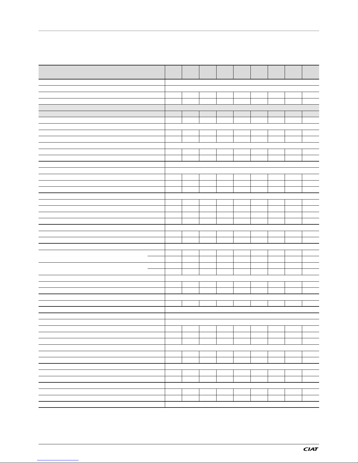
4 - PHYSICAL PROPERTIES AND ELECTRICAL DATA FOR LX UNITS
4.1 - Physical properties of LX units
LX 2308 to 4608 units
LX ST-HE 2308 2528 2628 3028 3428 3828 4008 4408 4608
Sound levels
LX ST-HE
Sound power
(1)
dB(A) 103 101 104 103 104 103 105 105 105
Sound pressure at 10 m
(2)
dB(A) 70 70 71 70 71 70 72 72 72
LX ST-HE + low noise option
Sound power
(1)
dB(A) 98 98 99 98 98 98 101 99 99
Sound pressure at 10 m
(2)
dB(A) 65 66 66 65 65 65 68 65 65
LX ST-HE + Xtra low noise option
Sound power
(1)
dB(A) 94 93 95 94 94 94 99 95 96
Sound pressure at 10 m
(2)
dB(A) 61 60 62 61 61 61 66 62 63
LX ST-HE + Super low noise option
Sound power
(1)
dB(A) 92 91 93 92 93 93 97 94 95
Sound pressure at 10 m
(2)
dB(A) 59 58 60 59 60 60 64 61 62
Dimensions
Standard unit
Length mm 7186 8380 8380 9574 11962 11962 11962 11962 13157
Width mm 2253 2253 2253 2253 2253 2253 2253 2253 2253
Height mm 2297 2297 2297 2297 2297 2297 2297 2297 2297
Operating weight
(3)
LX ST standard kg 5687 6072 6376 6827 8070 8211 8790 8867 9181
LX ST Unit + low noise option kg 6018 6403 6707 7158 8441 8582 9162 9239 9553
LX HE standard kg 5687 6072 6376 6827 8070 8211 8790 8867 9181
LX HE Unit + Low noise option kg 6018 6403 6707 7158 8441 8582 9162 9239 9553
Compressors 06T semi-hermetic screw, 50 r/s
Circuit A 1 1 1 1 1 1 1 1 1
Circuit B 1 1 1 1 1 1 1 1 1
Refrigerant
(3)
R134a
Circuit A
kg 69 72 69 75 76 76 110 116 132
tCO
2
e 98,7 103,0 98,7 107,3 108,7 108,7 157,3 165,9 188,8
Circuit B
kg 65 63 76 79 108 120 116 124 120
tCO
2
e 93,0 90,1 108,7 113,0 154,4 171,6 165,9 177,3 171,6
Oil
Circuit A l 27,6 27,6 27,6 27,6 27,6 27,6 36,0 36,0 36,0
Circuit B l 23,5 23,5 27,6 27,6 36,0 36,0 36,0 36,0 36,0
Capacity control Connect Touch, electronic expansion valve (EXV)
Minimum capacity % 15 15 15 15 15 15 15 15 15
Air-cooled exchanger Aluminium micro-channel coils (MCHE)
Fans Axial type, with rotating impeller
LX ST/HE
Quantity 12 14 14 16 20 20 20 20 22
Maximum total air ow l/s 54166 63194 63194 72221 90277 90277 90277 90277 99304
Maximum rotation speed r/s 15,7 15,7 15,7 15,7 15,7 15,7 15,7 15,7 15,7
LX ST/HE Unit + Xtra low noise option
Maximum total air ow l/s 41000 47833 47833 54667 68333 68333 68333 68333 75167
Maximum rotation speed r/s 11,7 11,7 11,7 11,7 11,7 11,7 11,7 11,7 11,7
Exchanger Flooded multi-pipe type
Water volume l 119 11 9 130 140 164 174 180 189 189
Max. water-side operating pressure without hydraulic module
kPa 1000 1000 1000 1000 1000 1000 1000 1000 1000
Water connections with or without hydraulic module Victaulic
®
type
Connections inch 6 6 6 8 6 6 6 6 6
External diameter mm
168,3 168,3 168,3 219,1 168,3 168,3 168,3 168,3 168,3
Casing paintwork Colour code RAL 7035 & RAL 7024
(1) In dB ref=10
-12
W, 'A' weighted. Declared dual-number noise emission values in accordance with ISO 4871 with an associated uncertainty of +/-3dB(A). Measured
in accordance with ISO 9614-1 and certied by Eurovent.
(2) In dB ref 20 µPa, 'A' weighted. Declared dual-number noise emission values in accordance with ISO 4871 with an associated uncertainty of +/-3dB(A).
For information, calculated from the sound power Lw(A).
(3) Values are guidelines only. Refer to the unit name plate.
EN-17 POWERCIAT LX ST/HE/XE
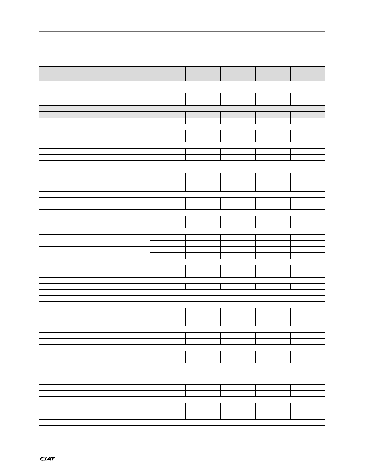
4.1 - Physical properties of LX units
LX 0808 to 2158 units
LX XE 0808 0908 1008 1108 1358 1528 1858 2008 2158
Sound levels
LX XE
Sound power
(1)
dB(A) 99 99 99 99 101 99 101 99 103
Sound pressure at 10 m
(2)
dB(A) 67 67 67 67 69 67 68 67 70
LX XE + low noise option
Sound power
(1)
dB(A) 93 93 94 95 95 95 97 96 97
Sound pressure at 10 m
(2)
dB(A) 61 61 62 63 63 63 65 63 64
LX XE + Xtra low noise option
Sound power
(1)
dB(A) 87 87 87 90 91 91 93 92 94
Sound pressure at 10 m
(2)
dB(A) 55 55 55 58 59 59 60 59 61
LX XE + Super low noise option not available
Sound power
(1)
dB(A) - - - - - - - - -
Sound pressure at 10 m
(2)
dB(A) - - - - - - - - -
Dimensions
Standard unit
Length mm 3604 3604 3604 4798 4798 5992 7186 7186 7186
Width mm 2253 2253 2253 2253 2253 2253 2253 2253 2253
Height mm 2297 2297 2297 2297 2297 2297 2297 2297 2297
Operating weight
(3)
LX XE standard kg 3190 3224 3245 3834 3899 4261 4962 5093 5376
LX XE + low noise option kg 3458 3492 3513 4133 4198 4560 5293 5424 5707
Compressors 06T semi-hermetic screw, 50 r/s
Circuit A 1 1 1 1 1 1 1 1 1
Circuit B 1 1 1 1 1 1 1 1 1
Refrigerant
(3)
R134a
Circuit A
kg 37 35 35 51 52 54 58 58 65
tCO
2
e 52,9 50,1 50,1 72,2 74,4 76,5 82,9 82,9 93,0
Circuit B
kg 38,5 36 37 36,5 37 32,5 59 62 58
tCO
2
e 55,1 51,5 52,9 52,2 52,9 46,5 84,4 88,7 82,9
Oil
Circuit A l 20,8 20,8 20,8 23,5 23,5 23,5 23,5 23,5 27,6
Circuit B l 20,8 20,8 20,8 20,8 20,8 20,8 23,5 23,5 23,5
Capacity control Connect Touch, electronic expansion valve (EXV)
Minimum capacity % 15 15 15 15 15 15 15 15 15
Air-cooled exchanger Aluminium micro-channel coils (MCHE)
Fans
LX XE Axial type, with rotating impeller
Quantity 6 6 6 8 8 9 11 12 12
Maximum total air ow l/s 28920 28920 28920 38560 38560 43380 53020 57840 57840
Maximum rotation speed r/s 15,7 15,7 15,7 15,7 15,7 15,7 15,7 15,7 15,7
LX XE + Xtra low noise option
Maximum total air ow l/s 23580 23580 23580 31440 31440 35370 43230 47160 47160
Maximum rotation speed r/s 11,7 11,7 11,7 11,7 11,7 11,7 11,7 11,7 11,7
Exchanger Flooded multi-pipe type
Water volume l 58 61 61 66 70 77 79 94 98
Max. water-side operating pressure without hydraulic module
kPa 1000 1000 1000 1000 1000 1000 1000 1000 1000
Hydraulic module (option)
Pump, Victaulic screen lter, relief valve, water and air vent valve,
pressure sensors
Pump
Centrifugal pump, monocell, 48,3r/s, low or high pressure (as required),
single or dual (as required)
Expansion vessel volume l 50 50 50 50 50 80
Max. water-side operating pressure with hydraulic module
kPa 400 400 400 400 400 400
Water connections with or without hydraulic module Victaulic
®
type
Connections inch 5 or 4 5 or 4 5 or 4 5 or 4 5 or 4 5 or 4 5 6 6
External diameter mm
114.3 or
141.3
114.3 or
141.3
114.3 or
141.3
114.3 or
141.3
114.3 or
141.3
114.3 or
141.3
141,3 168,3 168,3
Casing paintwork Colour code RAL 7035 & RAL 7024
(1) In dB ref=10
-12
W, 'A' weighted. Declared dual-number noise emission values in accordance with ISO 4871 with an associated uncertainty of +/-3dB(A). Measured
in accordance with ISO 9614-1 and certied by Eurovent.
(2) In dB ref 20µPa, 'A' weighted. Declared dual-number noise emission values in accordance with ISO 4871 with an associated uncertainty of +/-3dB(A). For information,
calculated from the sound power Lw(A).
(3) Values are guidelines only. Refer to the unit name plate.
4 - PHYSICAL PROPERTIES AND ELECTRICAL DATA FOR LX UNITS
POWERCIAT LX ST/HE/XE EN-18
4.1 - Physical properties of LX units
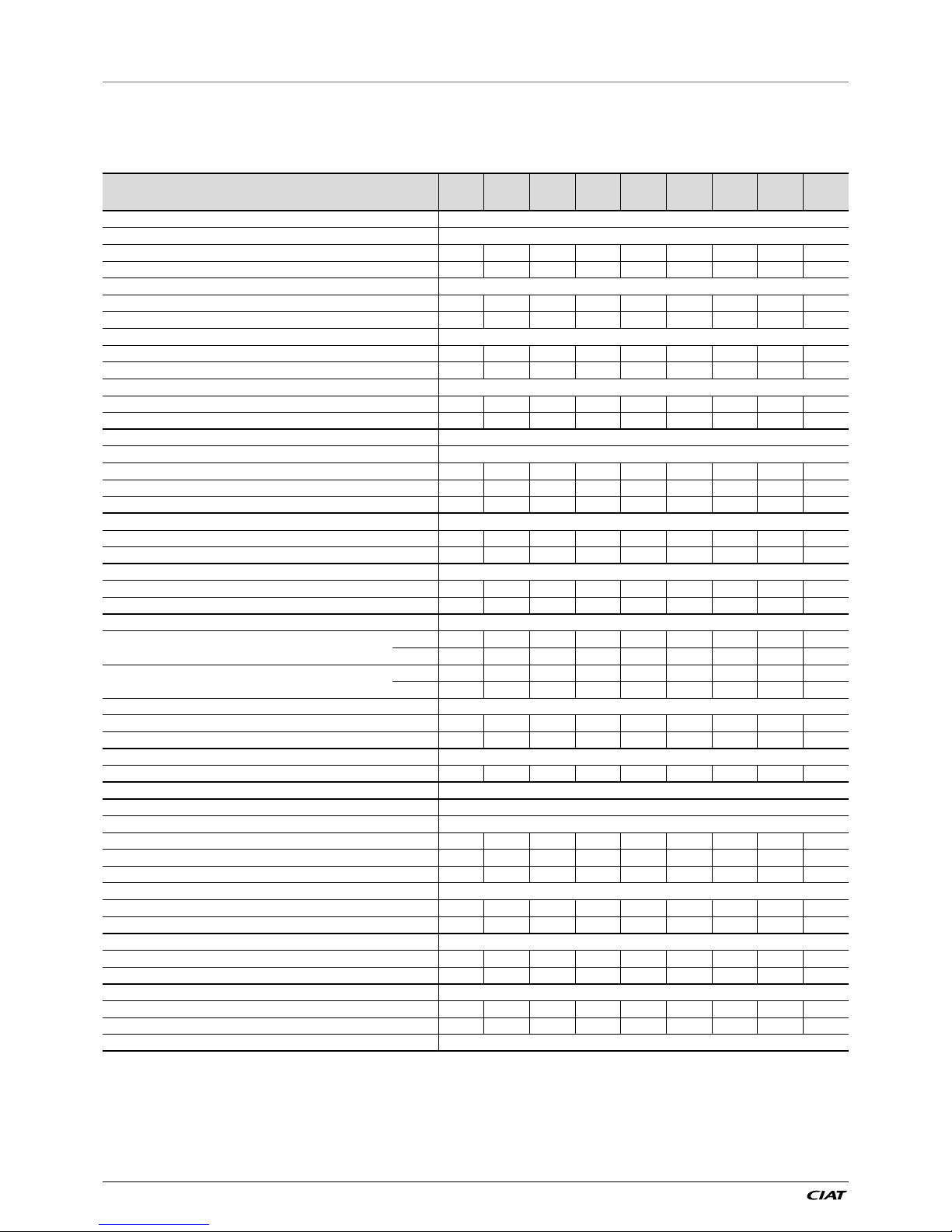
LX 2308 to 4608 units
LX XE 2308 2528 2628 3028 3428 3828 4008 4408 4608
Sound levels
LX XE
Sound power
(1)
dB(A) 103 101 104 102 103 102 104 104 104
Sound pressure at 10 m
(2)
dB(A) 70 70 71 69 70 69 71 71 71
LX XE + low noise option
Sound power
(1)
dB(A) 98 97 99 98 98 98 100 99 99
Sound pressure at 10 m
(2)
dB(A) 65 65 66 65 65 65 67 65 65
LX XE + Xtra low noise option
Sound power
(1)
dB(A) 94 94 95 94 94 94 99 95 96
Sound pressure at 10 m
(2)
dB(A) 61 61 62 61 61 61 66 62 63
LX XE + Super low noise option not available
Sound power
(1)
dB(A) - - - - - - - - -
Sound pressure at 10 m
(2)
dB(A) - - - - - - - - -
Dimensions
Standard unit
Length mm 7186 8380 8380 9574 11962 11962 11962 11962 13157
Width mm 2253 2253 2253 2253 2253 2253 2253 2253 2253
Height mm 2297 2297 2297 2297 2297 2297 2297 2297 2297
Operating weight
(3)
LX XE standard kg 5687 6072 6376 6827 8070 8211 8790 8867 9181
LX XE + low noise option kg 6018 6403 6707 7158 8441 8582 9162 9239 9553
Compressors 06T semi-hermetic screw, 50 r/s
Circuit A 1 1 1 1 1 1 1 1 1
Circuit B 1 1 1 1 1 1 1 1 1
Refrigerant
(4)
R134a
Circuit A
kg 69 72 69 75 76 76 110 116 132
tCO
2
e 98,7 103,0 98,7 107,3 108,7 108,7 157,3 165,9 188,8
Circuit B
kg 65 63 76 79 108 120 116 124 120
tCO
2
e 93,0 90,1 108,7 113,0 154,4 171,6 165,9 177,3 171,6
Oil
Circuit A l 27,6 27,6 27,6 27,6 27,6 27,6 36,0 36,0 36,0
Circuit B l 23,5 23,5 27,6 27,6 36,0 36,0 36,0 36,0 36,0
Capacity control Connect Touch, electronic expansion valve (EXV)
Minimum capacity % 15 15 15 15 15 15 15 15 15
Air-cooled exchanger Aluminium micro-channel coils (MCHE)
Fans Axial type, with rotating impeller
LX XE
Quantity 12 14 14 16 20 20 20 20 22
Maximum total air ow l/s 57840 67480 67480 77120 96400 96400 96400 96400 106040
Maximum rotation speed r/s 15,7 15,7 15,7 15,7 15,7 15,7 15,7 15,7 15,7
LX XE + Xtra low noise option
Maximum total air ow l/s 47160 55020 55020 62880 78600 78600 78600 78600 86460
Maximum rotation speed r/s 11,7 11,7 11,7 11,7 11,7 11,7 11,7 11,7 11,7
Exchanger Flooded multi-pipe type
Water volume l 119 11 9 130 140 164 174 180 189 189
Max. water-side operating pressure without hydraulic module
kPa 1000 1000 1000 1000 1000 1000 1000 1000 1000
Water connections with or without hydraulic module Victaulic
®
type
Connections inch 6 6 6 8 6 6 6 6 6
External diameter mm 168,3 168,3 168,3 219,1 168,3 168,3 168,3 168,3 168,3
Casing paintwork Colour code RAL 7035 & RAL 7024
(1) In dB ref=10
-12
W, 'A' weighted. Declared dual-number noise emission values in accordance with ISO 4871 with an associated uncertainty of +/-3dB(A). Measured
in accordance with ISO 9614-1 and certied by Eurovent.
(2) In dB ref 20µPa, 'A' weighted. Declared dual-number noise emission values in accordance with ISO 4871 with an associated uncertainty of +/-3dB(A). For information,
calculated from the sound power Lw(A).
(3) Values are guidelines only. Refer to the unit name plate.
4 - PHYSICAL PROPERTIES AND ELECTRICAL DATA FOR LX UNITS
 Loading...