

CIAT HYDROCIAT LW ST, HYDROCIAT LW HE Series Series Manual
Water chillers
Heat pump
Energy excellence
Compact and reliable
Screw compressors
Flooded shell and tubes evaporator
Self-adjusting electronic control
Touch screen control interface
HeatingCooling Heat
recovery
Use
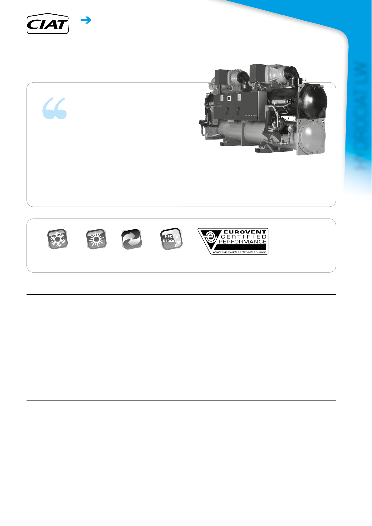
The latest generation of HYDROCIAT LW water chillers and water-to-
water heat pumps are the perfect solution for all heating and cooling
applications in the Office, Healthcare, Industry, Administration,
Shopping Centres and Collective Housing markets.
HYDROCIAT is optimised to use ozone-friendly HFC R134a
refrigerant.
This range guarantees compliance with the most demanding
requirements for high energy efficiency and CO
with the various applicable European directives and regulations.
reduction to comply
2
Cooling capacity 273-1756 kW
HYDROCIAT LW
Heating capacity 317-1989 kW
When producing chilled water, these units can be connected to a
drycooler or a water cooling tower.
With the heat pump option, the units can produce hot water for
heating applications. They can also be used in cooling mode by
reversing the cycle on the hydraulic circuits using a set of valves
(hydraulic valves not supplied).
Range
HYDROCIAT LW ST series
Standard cooling or heating version
The product is optimised to meet the most demanding technical
and economic requirements.
HEAT PUMPS - AIR CONDITIONING - REFRIGERATION - AIR HANDLING - HEAT EXCHANGE - NA 18.752 B
HYDROCIAT LW HE series
High Efficiency cooling or heating version
The product is optimised for high energy efficiency applications
for which optimum SEER, SEPR and SCOP values are required,
ensuring operating costs are kept to a minimum.
1
DescRiption
Water chillers
Heat pump
HYDROCIAT LW
HYDROCIAT units are packaged machines supplied as standard
with the following components:
- Twin-screw semi-hermetic compressors
- Shell and tube type chilled-water evaporator
- Shell and tube type hot water condenser
- Electrical power and remote control cabinet:
•
400 V-3ph-50 Hz general power supply (+/-10%) + Earth
• transformer fitted as standard on the machine for supplying the
remote control circuit with 24 V
- Connect Touch electronic control module
- Casing for indoor installation
DescRiption
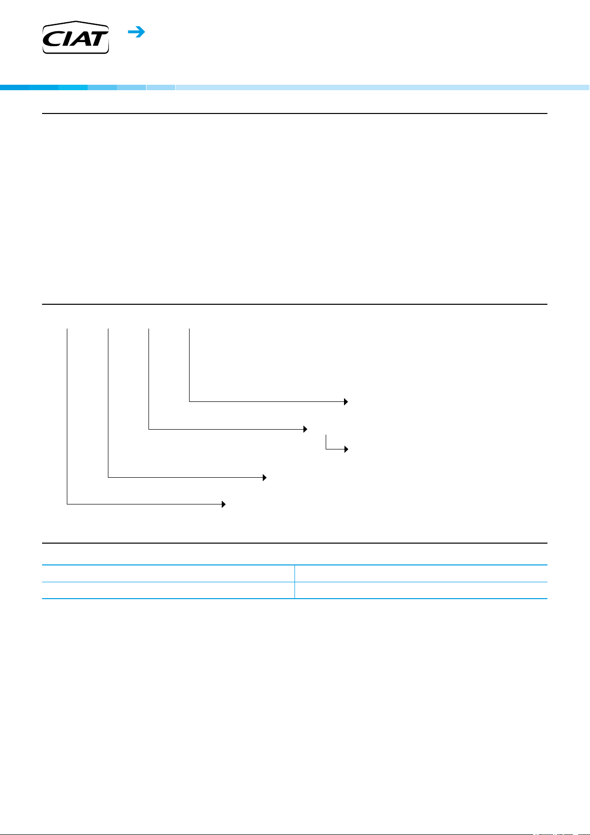
LW ST 708 D
The entire HYDROCIAT range complies with the following EC
directives and standards:
- Machinery Directive 2006/42/EC
- Electromagnetic Compatibility Directive 2014/30/EU
- EMC immunity and emissions EN 61800-3 'C3'
- Low Voltage Directive 2014/35/EU
- RoHS 2011/65/EU
- Pressure Equipment Directive (PED) 2014/68/EU
- Machinery Directive EN 60-204 -1
- Refrigeration systems and heat pumps EN 378-2.
- Regulation (EU) 2016/2281 implementing Directive 2009/125/EC
with regard to ecodesign requirements
D > generation of the range
708 > unit size
8 > unit equipped with economiser
ST > Standard version
HE > High Efficiency version
> cooling or heating version
function
configURation
ST Standard HE High Efciency
ST LN option Standard Low Noise HE LN option High Efficiency Low Noise
2
HEAT PUMPS - AIR CONDITIONING - REFRIGERATION - AIR HANDLING - HEAT EXCHANGE - NA 18.752 B
Water chillers
Heat pump
DescRiption of the components
■ Compressors
- Twin-screw semi-hermetic type
- 2 screws fitted on ball and roller bearings
- Continuous power control
- Built-in electric motor, cooled by intake gases
- Integral electronic protection of the motor against thermal and
electrical overloads
- Monitoring of rotation direction, absence of phase, over and
under voltage, and power supply failure
- Monitoring of lubrication under differential pressure
- Built-in oil filter
- Internal pressure surge valve and valve to prevent reverse
rotation during shutdown phases
- Monitoring of maximum head pressure
- Silencer fitted at the discharge to reduce pulses from the
discharged gas
- Star-delta start limiting the in-rush current
■ Shell and tube evaporator
- High performance glandless technology
- Copper tube bundle with internal and external grooves
- 19 mm thermal insulation
- Victaulic type coupling
- Maximum pressure, water side, of 10 bar (21 bar as option)
■ Shell and tube condenser
- Copper tube bundle with internal and external grooves
- 19 mm thermal insulation (option)
- Built-in oil separator
- Victaulic type coupling
- Maximum pressure, water side, of 10 bar (21 bar as option)
■ Economiser function (available on models
designated by the figure 8)
- 1 brazed plate heat exchanger on each refrigerating circuit
- Refrigerant flow rate controlled by an electronic expansion valve
- The economiser function allows the cooling capacity to be
significantly increased and provides considerable optimisation
of the machine's energy efficiency
■ Refrigerant accessories
- Dehumidifier filters with rechargeable cartridges
- Hygroscopic sight glasses
- Electronic expansion valves
■ Regulation and safety instruments
- High and low pressure sensors
- Safety relief valves on refrigerating circuit
- Evaporator antifreeze protection sensor
- Chilled water and hot water control sensors
- Electronic evaporator water circulation controller
■ Electrical cabinet
- Electrical cabinet index of protection IP23
- Safety disconnect switch
- 24 V control circuit
- Remote control transformer circuit
- Protection of the power and control circuits
- Compressor motor contactor
- Connect Touch microprocessor-controlled electronic control module
- Electrical cabinet wire numbers
- Location of main components
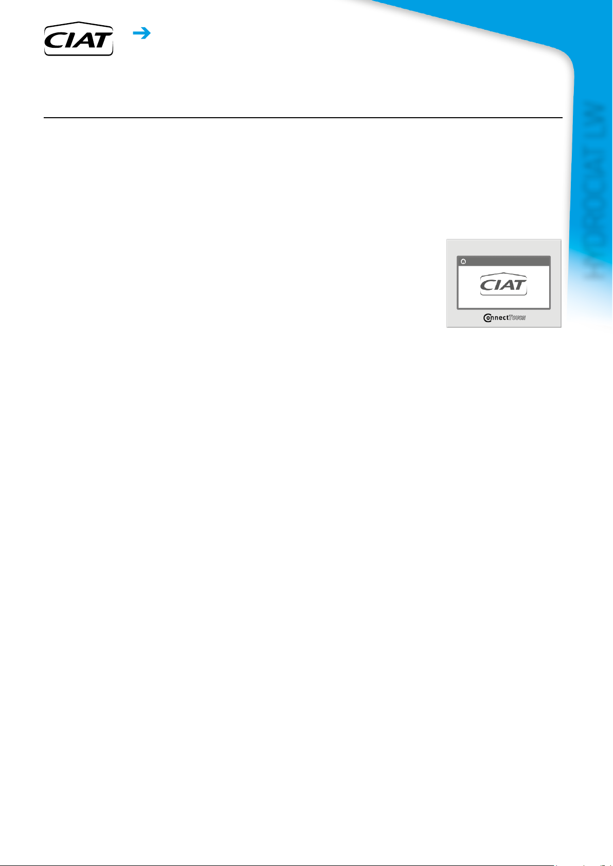
■ Connect Touch control module
- User interface with 5 inch touchscreen (7-inch option)
- Intuitive, user-friendly navigation using icons
- Clear information display in 8 languages
(F-GB-E-NL-I-S-P + Chinese)
HYDROCIAT LW
The electronic control module
performs the following main
functions:
- regulation of the chilled water temperature (at the return or at
the outlet)
- regulation of the water temperature based on the outdoor
temperature (water law)
- regulation for low temperature energy storage
- second setpoint management
- complete management of compressors with start-up sequence,
timer and operating time balancing
- self-regulating and proactive functions with adjustment of
settings on drift control
- continuous power control slide system on the compressors
according to the thermal requirements
- management of compressor short cycle protection
- phase reversal protection
- management of occupied/unoccupied modes (according to the
time schedule)
- equalisation of compressor operating hours
- condensing temperature limitation (option)
- diagnosis of fault and operating statuses
- management of a fault memory allowing a log of the last 50
incidents to be accessed, with operating readings taken when
the fault occurs
- blackbox memory
- master/slave management of two machines with equalisation of
operating hours and automatic switching
in case of a machine fault
- weekly and hourly time schedule for the machine, including 16
periods of absence
- display of all machine parameters (3 access levels, User/
Maintenance/Factory, password-protected): temperature,
setpoints, pressures, flow rate, operation time.
- display of trend curves for the main values
- storage of maintenance manual, wiring diagram and spare parts list.
■ Unit construction
- Electrical cabinet in graphite grey (RAL 7024)
- Compressors in grey (RAL 7037)
HEAT PUMPS - AIR CONDITIONING - REFRIGERATION - AIR HANDLING - HEAT EXCHANGE - NA 18.752 B
3
Water chillers
In
HYDROCIAT
connect
touch
04 - 2016
Instruction manual
EN7488914-00
Heat pump
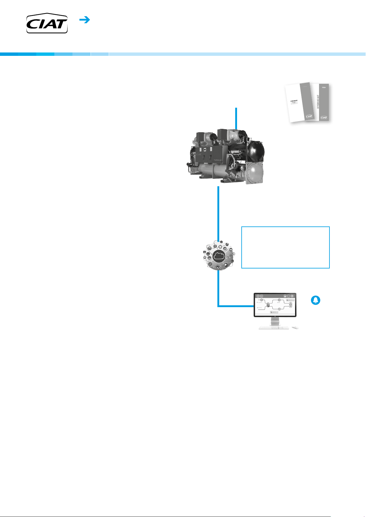
■
Remote management
Connect Touch is equipped as standard with an RS485 port and an
ETHERNET (IP) connection, offering a range of options for remote
management, monitoring and diagnostics.
Using the integrated Webserver, a simple internet connection uses
the unit's IP address to access the Connect Touch interface on
the PC, facilitating everyday management tasks and maintenance
operations.
Numerous communication protocols are available: MODBUS/
JBUS RTU(RS485) or TC/IP as standard, LONWORKS –
BACNET IP optional, enabling integration with most CMS/BMS
Several contacts are available as standard, enabling the machine
to be controlled remotely by wired link:
- automatic operation control: when this contact is open, the
machine stops
- setpoint 1/setpoint 2 selector: when this contact is closed,
a second cooling setpoint is activated (energy storage or
unoccupied mode, for example)
- heating/cooling operating mode selection
- power limitation: closing the contact concerned allows the power
or refrigerating consumption of the machine to be limited by
stopping one or more compressors (this limit can be set with a
parameter)
- fault reporting: this contact indicates the presence of a major
fault which has caused one or both refrigerating circuits to stop
- operational status reporting indicates that the unit is in production
mode
- 0-10V signal output for external variable speed pump
management
Contacts available as an option:
- setpoint adjustable via 4-20 mA signal: this input is used to
adjust the setpoint in COOLING mode
- power limitation adjustable by 4-20 mA signal
- second power limitation level
- power indication: analogue output (0-10 V) providing an
indication of the unit's load rate.
- user fault reporting enables integration of a fault in the water
loop
- general fault reporting: this contact indicates that the unit has
stopped completely
- alert reporting: this contact indicates the presence of a minor
fault which has not caused the circuit affected to stop.
- end of storage signal: enables return to the second setpoint at
the end of the storage cycle
- schedule override: closing this contact cancels the time schedule.
- drycooler management
HYDROCIAT LW
Direct access to technical literature
-Instruction manual
-Electrical diagram
- Spare parts list
Web server integrate as
standard
IP address
Remote management via web server
Connection to RJ port
Connection via IP address
All the HMI functionalities available
on the PC
Simplified remote monitoring
EN7488914-00
04 - 2016
HYDROCIAT
struction manual
E-mail alerts
(2 addresses)
n Maintenance alert as standard
Connect Touch has two maintenance reminder functions as
standard, making users aware of the need to regularly perform
maintenance operations and to guarantee the service life and
performance of the unit. These two functions can be activated
independently.
A reminder message appears on the unit's HMI screen, and stays
there until it is acknowledged by the maintenance operator. The
- the scheduled maintenance reminder: when activated, this function
enables the period between two maintenance inspections to be set.
This period may be set by the operator in either days, months or
operating hours, depending on the application.
- the compulsory F-GAS sealing test maintenance reminder:
when
activated, this function, which is the default factory setting, enables
the period between two sealing tests to be selected, according to the
refrigerant charge, in compliance with the F-GAS regulations.
information and alert relating to these functions are available on
the communication bus to be used on the CMS/BMS.
4
HEAT PUMPS - AIR CONDITIONING - REFRIGERATION - AIR HANDLING - HEAT EXCHANGE - NA 18.752 B
Water chillers
Heat pump
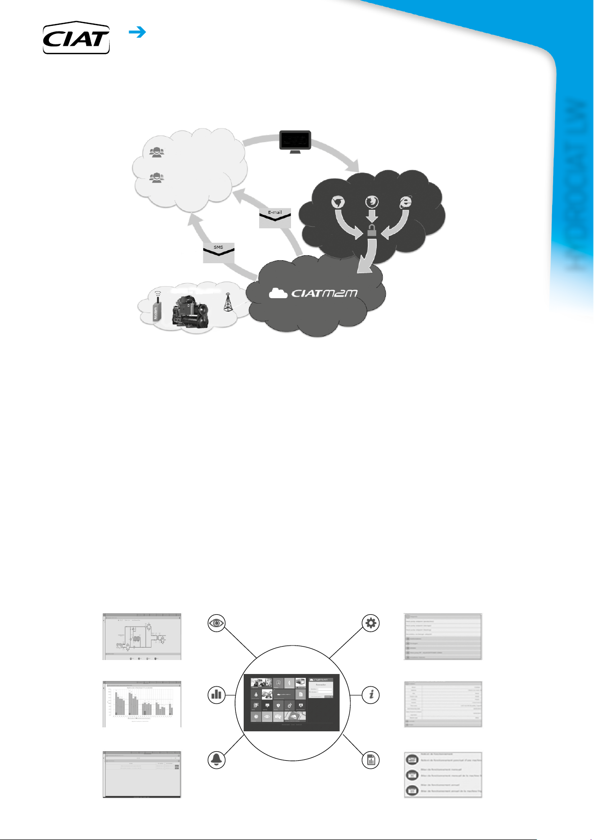
n CIATM2M, the CIAT supervision solution
CIATM2M is a remote supervision solution dedicated to monitoring and controlling several CIAT machines in real time.
Users
Client
CIAT service
technician
SMS alerts
Telecom operator
Computer
E-mail alerts
Advantages
- Access to the operating trend curves for analysis
- Improved energy performance
- Improved availability rate for the machines
Functions
CIATM2M will send data in real time to the supervision website,
www.ciatm2m.com.
The machine operating data can be accessed from any PC,
smartphone or tablet.
Any event can configured to trigger a mail alert.
Parameters monitored:
- Overview
- Control panel for the controllers
- Events
- Temperature curves
Monthly and annual reports are available to analyse:
- The performance and operation of the machine
Example: operating curves and time, number of compressor
start-ups, events, preventive maintenance actions to be
performed, etc.
Incidents such as a drift in the measurements on a temperature
sensor, incorrectly set control parameters, or even incorrect
settings between one compressor stage and the other are
immediately detected, and the corrective actions put in place.
Login to
www.ciatm2m.com
Google
Chrome
INTERNET
Mozilla
Firefox
Internet
Explorer 9
Equipment
This kit can be used on both machines which are already in use
(existing inventory), and on new machines.
CIATM2M kit contents
- 1 GPRS / 3G modem
- 1 SIM card
- One 24 VDC power supply
- 1 power protection device
- 1 GSM antenna
- Rail mounting
- Enclosed casing to protect the equipment during transport
- Packing box for cable routing (bus, power supply, Ethernet)
Compatibility
Up to three machines per CIATM2M kit
HYDROCIAT LW
Overview
Curves
Events (real time and
archives)
Supervision platform
CIATM2M
HEAT PUMPS - AIR CONDITIONING - REFRIGERATION - AIR HANDLING - HEAT EXCHANGE - NA 18.752 B
Parameters
Information
Reports
5
Water chillers
Heat pump
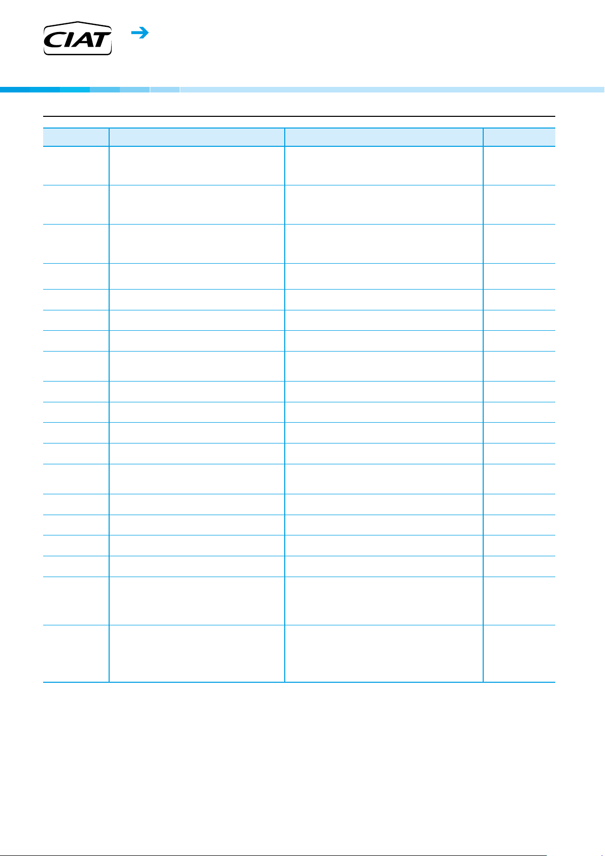
HYDROCIAT LW
options
Options Description Advantages LW ST/HE
Medium-temperature
brine solution
Low-temperature
brine solution
Light-brine solution,
down to -3°C
Unit supplied in two
assembled parts
Evap. single pump
power/control circuit
230V electrical plug
Evaporator with one
pass less
Master/slave
operation
Condenser with one
pass less
21 bar evaporator
Single power
connection point
21 bar condenser
Reversed
evaporator water
connections
Reversed condenser
water connections
Condenser
insulation
Service valve set
Lon gateway
Control for low cond.
temperature
Implementation of new control algorithms and redesigned
evaporator to allow chilled brine solution production down
to -6°C when ethylene glycol is used (-3°C with propylene
glycol)
Implementation of new control algorithms and redesigned
evaporator to allow chilled brine solution production
down to -12°C when ethylene glycol is used (-8°C with
propylene glycol)
Implementation of new control algorithms and redesigned
evaporator to allow chilled brine solution production down
to -3°C when ethylene glycol is used (0°C with propylene
glycol)
The unit is equipped with anges that allow disassembly
of the unit on site
Unit equipped with an electrical power and control circuit
for one pump evaporator side
230V AC power supply source provided with plug socket
and transformer (180 VA, 0,8 Amps)
Evaporator with one pass on the water side. Evaporator
inlet and outlet on opposite sides.
Unit equipped with supplementary water outlet
temperature sensor kit (to be eld installed) allowing
master/slave operation of two units connected in parallel
Condenser with one pass on the water side. Condenser
inlet and outlet on opposite sides.
Reinforced evaporator for extension of the maximum
water-side service pressure to 21 bar (standard 10 bar)
Unit power connection via one main supply connection Quick and easy installation 2800/4628
Reinforced condenser for extension of the maximum
water-side service pressure to 21 bar (standard 10 bar)
Evaporator with reversed water inlet/outlet
Condenser with reversed water inlet/outlet
Thermal condenser insulation
Liquid line valve (evaporator inlet) and compressor
suction line valve
Bi-directional communication board complying with Lon
Talk protocol
Output signal (0-10 V) to control the condenser water
inlet valve
Covers specic applications such as ice storage and industrial
processes
Covers specic applications such as ice storage and industrial
processes
Matches with most application requirements for ground-sourced
heat pumps and ts with many industrial processes requirements
Facilitates installation in plant rooms with limited access
Quick and easy installation: the control of xed speed pumps is
embedded in the unit control
Permits connection of a laptop or an electrical device during unit
commissioning or servicing
Easy to install, depending on site. Reduced pressure drops
Optimised operation of two units connected in parrallel operation
with operating time equalisation
Easy to install, depending on site. Reduced pressure drops
Covers applications with a high water column evaporator side
(typically high buildings)
Covers applications with a high water column condenser side
(typically high buildings)
Easy installation on sites with specic requirements
Easy installation on sites with specic requirements
Minimizes thermal dispersions condenser side (key option for
heat pump or heat recovery applications)
Allow isolation of various refrigerant circuit components for
simplied service and maintenance
Connects the unit by communication bus to a building
management system
Simple installation: for applications with cold water at condenser
inlet (ex. ground-source, groundwater-source, supercial
water-source applications) the signal permits to control a 2 or
3-way valve to maintain condenser water temperature (and so
condensing pressure) at acceptable values
1328/1528/2628/3008
Only sizes :
Only HE sizes :
1328/1528
●
Only sizes:
4228/4408/4608/4628
708-3428
●
●
●
●
●
●
●
●
●
●
●
●
Compliance with
Swiss regulations
● ALL MODELS
Refer to the selection tool to find out which options are not compatible
Additional tests on the water heat exchangers: supply
(additional of PED documents) supplementary certicates
and test certications
6
Conformance with Swiss regulations
HEAT PUMPS - AIR CONDITIONING - REFRIGERATION - AIR HANDLING - HEAT EXCHANGE - NA 18.752 B
●
Water chillers
Heat pump
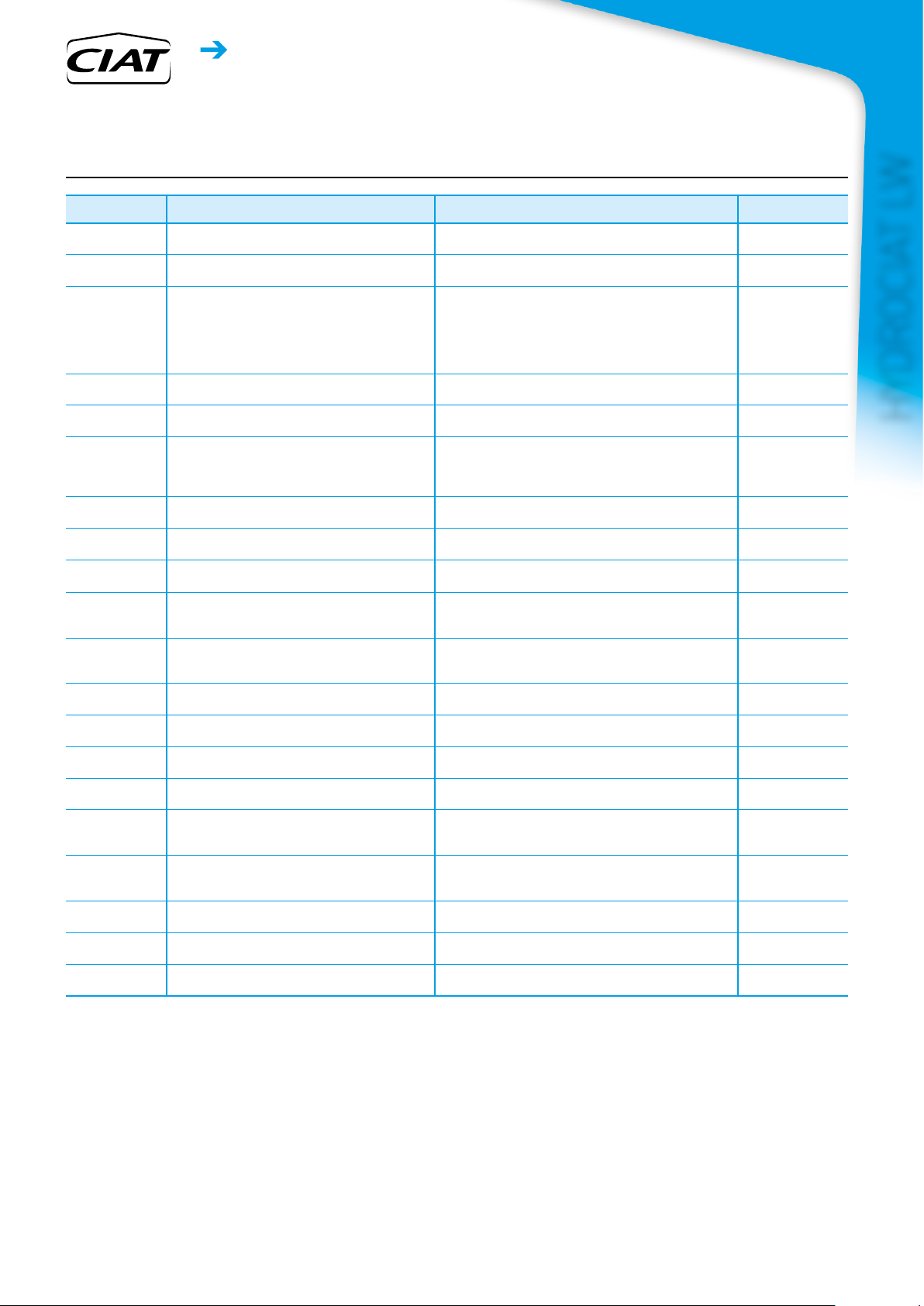
options
Options Description Advantages LW ST/HE
Compliance with
Russian regulations
Bacnet over IP
High condensing
temperature
Condensing
temperature limitation
Flanged evaporator
water connection kit
Specic dry cooler
control
Flanged condenser
water connection kit
Energy Management
Module
7" user interface
Input contact for
Refrigerant leak
detection
Compliance
with Australian
regulations
Low noise level Evaporator sound insulation 3 dB(A) quiter than standard unit 1308-4608
Evap. dual pumps
power/control circuit
Thermal compressor
insulation
Cond. single pump
power/control circuit
M2M supervision
(accessory)
Anti-vibration
mounts (kit)
Set point adjustment
by 4-20mA signal
Free Cooling dry
cooler management
Heat Pump
application
EAC certication Conformance with Russian regulations
Bi-directional high-speed communication using BACnet
protocol over Ethernet network (IP)
Optimized compressor for operation at high condensing
temperature
Limitation of the maximum condenser leaving water
temperature to 45°C
Victaulic piping connections with anged joints Easy installation
Control box for communication with the drycooler via a
bus. For OPERA drycooler need to select the cabinet
with option control cabinet manage by the chiller
Connect'Touch control"
Victaulic piping connections with anged joints Easy installation
Control board with additional inputs/outputs. See
Contacts available in option on control description.
Control supplied with a 7 inch colour touch screen user
interface
0-10 V signal to report any refrigerant leakage in the unit
directly on the controlller (the leak detector itself must be
supplied by the customer)
Unit approved to Australian code Conformance with Australian regulations
Unit equipped with an electrical power and control circuit
for two pumps evaporator side
The compressor is covered with a thermal insulation layer Prevents air humidity to condensate on the compressor surface
Unit equipped with an electrical power and control circuit
for one pump condenser side
Monitoring solution which allows customers to track and
monitor their equipment remotely in real time
Elastomer antivibratils mounts to be place under the unit
(Material classied B2 re class according to DIN 4102 ).
Connections to allow a 4-20mA signal input
Control & connections to a Free Cooling Drycooler Opera
or Vextra tted with option FC control box
Unit congurated for Heat Pump application, include
thermal condenser insulation
Easy and high-speed connection by ethernet line to a building
management system. Allows access to multiple unit parameters
Increased condenser leaving water temperature up to 63°C.
Allows applications with high condensing temperature (heat
pumps, installations with not generously sized dry-coolers or
more generally, installations with dry-coolers in hot climate).
NOTE: to ensure control of the condenser leaving water
temperature, this option must be tted on the units.
Reduced maximum power input and current absorption: power
cables and protection elements can therefore be downsized
Permits the use of an energy-efcient plug-and-play system
Extended remote control capabilities (Set-point reset by 0-20ma
input, ice storage end, demand limits, boiler on/off command...)
Enhanced ease of use.
Immediate customer notication of refrigerant losses to the
atmosphere, allowing timely corrective actions
Quick and easy installation: the control of xed speed pumps is
embedded in the unit control
Quick and easy installation: the control of xed speed pumps is
embedded in the unit control
Real-time expert technical support to improve equipment
availability and reports at customer hand to monitor and optimize
operating equipment.
Isolate unit from the building, avoid transmission of vibration and
associate noise to the buiding. Must be associate with exible
connection on water side
Easy energy managment, allow to adjust set point by a 4-20mA
external signal
Easy system managment, Extended control capabilities to a
dryccoler used in Free Cooling mode
Optimisation on heating mode & minimize thermal dispersions
condenser side
Available for all LW HE
Available for LW ST
708 / 858 / 1008, and
for higher LW ST sizes
only with heat pump
application option
708-3428
708-3428
●
●
●
●
HYDROCIAT LW
●
●
●
●
●
●
●
●
●
●
●
●
● ALL MODELS
Refer to the selection tool to find out which options are not compatible
HEAT PUMPS - AIR CONDITIONING - REFRIGERATION - AIR HANDLING - HEAT EXCHANGE - NA 18.752 B
7
Water chillers
Heat pump
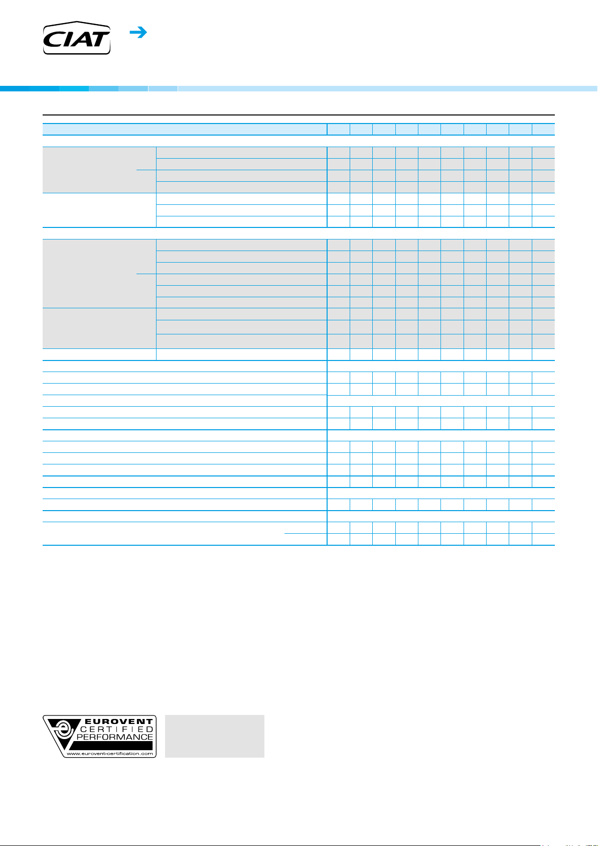
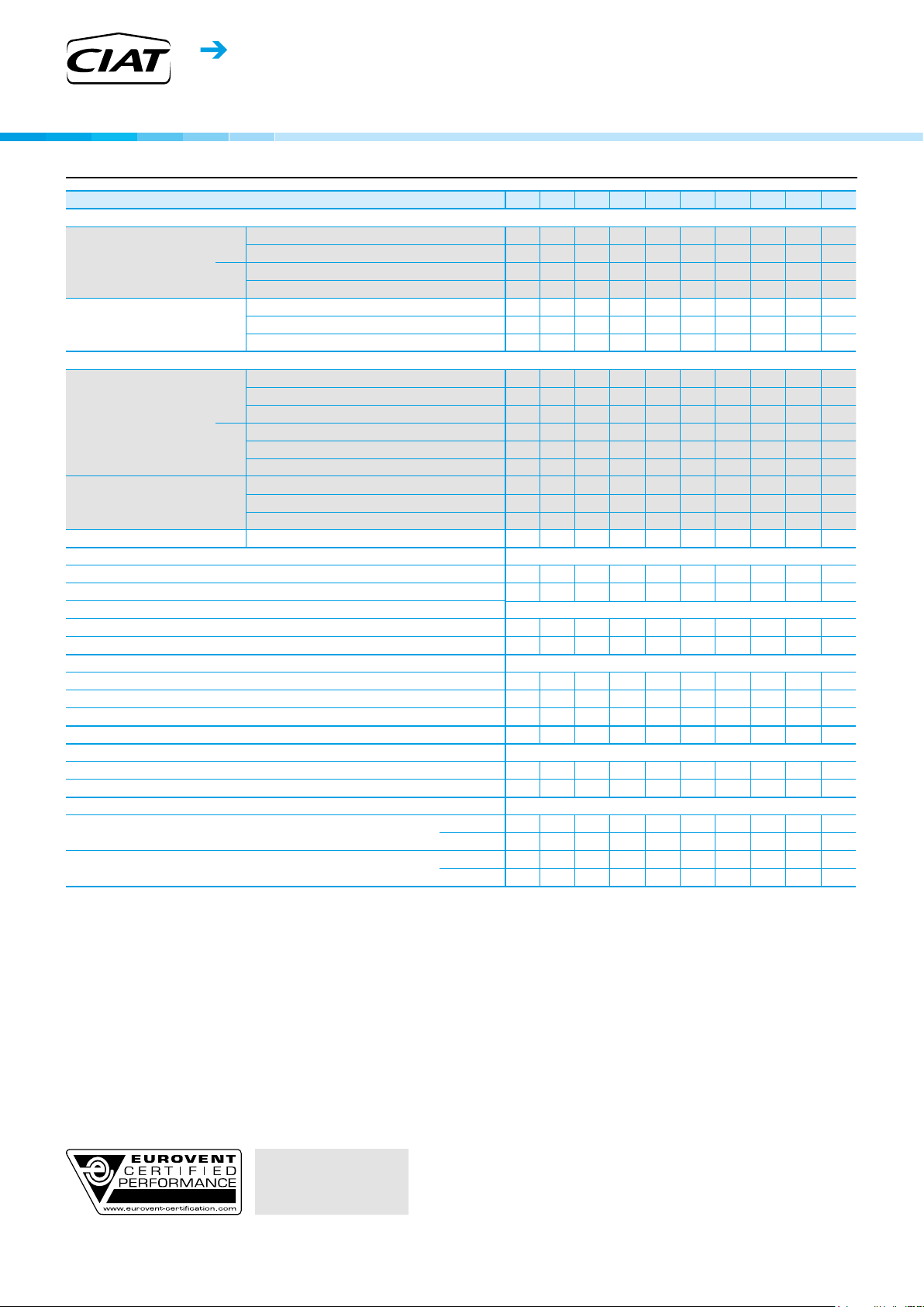
stanDaRD Unit technical chaRacteRistics
HYDROCIAT LW
LW ST / LW ST + Heat pump application option 708 858
Heating
Standard unit
Full load performances*
Standard unit
Seasonal energy efciency**
Cooling
Standard unit
Full load performances*
Standard unit
Seasonal energy efciency**
Integrated Part Load Value IPLV.SI kW/kW 6,843 6,708 6,722 6,664 6,897 6,905 6,891 7,351 7,321 7,184
Sound levels - standard unit
Sound power level
Sound pressure level at 1 m
Sound levels - unit with Low Noise option
Sound power level
Sound pressure level at 1 m
Dimensions - standard unit
Length mm 2724 2724 2724 2741 2741 2741 2741 3059 3059 3059
Width mm 928 928 928 936 936 936 936 1040 1040 1040
Height mm 1567 1567 1567 1692 1692 1692 1692 1848 1848 1848
Operating weight
Compressors Semi-hermetic screw compressors, 50 r/s
Circuit A 1 1 1 1 1 1 1 1 1 1
Refrigerant - standard unit R-134a
Circuit A
* In accordance with standard EN14511-3:2013.
** In accordance with standard EN14825:2016, average climate
HW1 Heating mode conditions: Evaporator entering/leaving water temperature 10°C/7°C, condenser entering/leaving water temperature
HW2 Heating mode conditions: Evaporator entering/leaving water temperature 10°C/7°C, condenser entering/leaving water temperature
CW1 Cooling mode conditions: Evaporator water entering/leaving temperature 12°C/7°C, condenser entering/leaving water temperature 30°C/35°C,
CW2 Cooling mode conditions: Evaporator water entering/leaving temperature 23°C/18°C, condenser entering/leaving water temperature
Ƞs heat
30/35°C
Ƞs cool
12/7°C
SEPR
12/7°C
IPLV.SI Calculations according to standard performances AHRI 551-591 (SI)
(1) In dB ref=10
(2) In dB ref 20µPa, (A) weighting. Declared dualnumber noise emission values in accordance with ISO 4871 (with an associated uncertainty of
(3) Weight shown is guideline only. Please refer to the unit nameplate
(1)
(2)
(1)
(2)
(3)
& SCOP
& SEER
Values calculated in accordance with EN14825:2016
30/35°C
Bold values compliant to Ecodesign regulation: (EU) No 2016/2281 for Comfort application
12/7°C
Nominal capacity kW 323 365 428 546 560 632 642 799 864 941
HW1
COP kW/kW 6,07 6,07 6,02 5,96 6,09 5,92 5,89 6,10 5,99 5,86
Nominal capacity kW 317 358 421 516 529 599 632 751 813 887
HW2
COP kW/kW 4,59 4,57 4,61 4,54 4,59 4,47 4,52 4,56 4,49 4,46
SCOP
30/35°C
HW1
ŋs heat
30/35°C
P
rated
Nominal capacity kW 273 307 359 460 473 532 538 677 730 792
CW1
EER kW/kW 5,32 5,30 5,24 5,23 5,35 5,18 5,17 5,39 5,30 5,19
Eurovent class - A A A A A A A A A A
Nominal capacity kW 345 365 458 585 566 596 656 845 884 887
CW2
EER kW/kW 6,71 6,24 6,57 6,40 6,28 5,74 6,21 6,50 6,21 5,70
Eurovent class - A A A A A A A A A A
SEER
ŋs cool
SEPR
30°C/35°C, evaporator and condenser fouling factor 0 m2. k/W
40°C/45°C, evaporator and condenser fouling factor 0 m2. k/W
evaporator and condenser fouling factor 0 m².K/W
30°C/35°C, evaporator and condenser fouling factor 0 m².K/W
Values calculated in accordance with EN14825:2016
+/-3dB(A)). Measured in accordance with ISO 9614-1 and certified by Eurovent.
+/-3dB(A)). For information, calculated from the sound power level Lw(A).
Comfort low temp. kWh/kWh 5,84 5,80 5,64 5,77 5,75 5,81 5,77 6,09 6,13 5,87
12/7°C
12/7°C
Process high temp.
12/7°C
-12
W, (A) weighting. Declared dualnumber noise emission values in accordance with ISO 4871 (with an associated uncertainty of
kWh/kWh 5,94 6,05 5,83 5,88 5,92 5,92 5,79 6,07 6,01 5,83
% 230 234 225 227 229 229 224 235 232 225
kW 421 432 507 650 666 748 760 952 1029 1102
% 231 229 223 228 227 229 228 241 242 232
kWh/kWh
dB(A) 95 95 95 99 99 99 99 99 99 99
dB(A) 78 78 78 82 82 82 82 82 82 82
dB(A) - - - 96 96 96 96 96 96 96
dB(A) - - - 78 78 78 78 78 78 78
teqCO
7,57 6,92 7,66 7,47 7,58 6,56 7,28 7,91 7,54 7,30
kg 2017 2036 2072 2575 2575 2613 2644 3247 3266 3282
kg 84 80 78 82 82 82 82 145 135 125
120 11 4 11 2 11 7 117 117 11 7 207 193 179
2
1008
1300 1302 1500 1508 1900 2100 2300
Eurovent certied values
8
HEAT PUMPS - AIR CONDITIONING - REFRIGERATION - AIR HANDLING - HEAT EXCHANGE - NA 18.752 B

Water chillers
Heat pump
stanDaRD Unit technical chaRacteRistics
LW ST / LW ST + Heat pump application option 708 858
Oil - standard unit SW220
Circuit A l 23,5 23,5 23,5 32 32 32 32 36 36 36
Capacity control Connect Touch, electronic expansion valves (EXV)
Minimum capacity
Evaporator Shell and tube ooded type
Water volume l 50 56 61 70 70 70 70 109 109 109
Water connections (Victaulic) in 5 5 5 5 5 5 5 6 6 6
Drain and vent connections (NPT) in 3/8 3/8 3/8 3/8 3/8 3/8 3/8 3/8 3/8 3/8
Max. water-side operating pressure kPa 1000 1000 1000 1000 1000 1000 1000 1000 1000 1000
Condenser Shell and tube type
Water volume l 55 55 55 76 76 76 76 109 109 109
Water connections (Victaulic) in 5 5 5 5 5 5 5 6 6 6
Drain and vent connections (NPT) in 3/8 3/8 3/8 3/8 3/8 3/8 3/8 3/8 3/8 3/8
Max. water-side operating pressure kPa 1000 1000 1000 1000 1000 1000 1000 1000 1000 1000
(4) Minimum unit capacity corresponds to a physical state of the unit and is given for indication only. The actual capacity at this stage depends on operating conditions.
(4)
% 15 15 15 15 15 15 15 15 15 15
1008
1300 1302 1500 1508 1900 2100 2300
HYDROCIAT LW
HEAT PUMPS - AIR CONDITIONING - REFRIGERATION - AIR HANDLING - HEAT EXCHANGE - NA 18.752 B
9
Water chillers
Heat pump
HYDROCIAT LW
stanDaRD Unit technical chaRacteRistics
LW ST / LW ST + Heat pump application option 2308 2800 3000 3008 3400 3800 4200 4600 4408 4608
Heating
Standard unit
Full load performances*
Standard unit
Seasonal energy efciency**
Cooling
Standard unit
Full load performances*
Standard unit
Seasonal energy efciency**
Integrated Part Load Value IPLV.SI kW/kW 7,175 7,539 7,751 7,596 8,066 7,835 7,730 7,575 7,957 7,892
Sound levels - standard unit
Sound power level
Sound pressure level at 1 m
(1)
(2)
Sound levels - unit with Low Noise option
Sound power level
Sound pressure level at 1 m
(1)
(2)
Dimensions - standard unit
Length mm 2780 4025 4025 4025 4730 4730 4730 4730 4790 4790
Width mm 1042 1036 1036 1036 1156 1156 1156 1156 1902 1902
Height mm 1898 1870 1870 1925 2051 2051 2051 2051 1515 1515
Operating weight
(3)
Compressors Semi-hermetic screw compressors, 50 r/s
Circuit A 1 1 1 1 1 1 1 1 1 1
Circuit B - 1 1 1 1 1 1 1 1 1
Refrigerant - standard unit R-134a
Circuit A
Circuit B
* In accordance with standard EN14511-3:2013.
** In accordance with standard EN14825:2016, average climate
HW1 Heating mode conditions: Evaporator entering/leaving water temperature 10°C/7°C, condenser entering/leaving water temperature
HW2 Heating mode conditions: Evaporator entering/leaving water temperature 10°C/7°C, condenser entering/leaving water temperature
CW1 Cooling mode conditions: Evaporator water entering/leaving temperature 12°C/7°C, condenser entering/leaving water temperature 30°C/35°C,
CW2 Cooling mode conditions: Evaporator water entering/leaving temperature 23°C/18°C, condenser entering/leaving water temperature
Ƞs heat
Ƞs cool
SEPR
IPLV.SI Calculations according to standard performances AHRI 551-591 (SI)
(1) In dB ref=10
(2) In dB ref 20µPa, (A) weighting. Declared dualnumber noise emission values in accordance with ISO 4871 (with an associated uncertainty of
(3) Weight shown is guideline only. Please refer to the unit nameplate
& SCOP
30/35°C
& SEER
12/7°C
Values calculated in accordance with EN14825:2016
12/7°C
Values calculated in accordance with EN14825:2016
30/35°C
Bold values compliant to Ecodesign regulation: (EU) No 2016/2281 for Comfort application
12/7°C
Nominal capacity kW 992 1204 1258 1349 1473 1578 1714 1829 1941 2027
HW1
COP kW/kW 6,04 5,88 5,79 5,89 6,26 6,03 5,84 5,73 6,01 5,98
Nominal capacity kW 967 1138 1190 1320 1384 1481 1612 1717 1891 1969
HW2
COP kW/kW 4,64 4,48 4,42 4,54 4,73 4,57 4,46 4,41 4,67 4,68
HW1
SCOP
ŋs heat
P
rated
30/35°C
30/35°C
kWh/kWh 5,90 6,05 5,96 5,99 6,19 5,84 5,64 5,47 5,73 5,70
% 228 234 231 232 240 226 218 211 221 220
kW 1160 1433 1498 1599 1754 1879 2041 2178 2292 2389
Nominal capacity kW 839 1017 1060 1141 1257 1342 1453 1547 1654 1728
CW1
EER kW/kW 5,39 5,25 5,18 5,30 5,68 5,51 5,36 5,29 5,59 5,60
Eurovent class - A A A A A A A A A A
Nominal capacity kW 922 1297 1348 1351 1678 1837 1916 1903 1944 2009
CW2
EER kW/kW 5,84 6,44 6,33 6,13 7,25 7,12 6,70 6,25 6,36 6,30
Eurovent class - A A A A A A A A A A
SEER
ŋs cool
SEPR
Comfort low temp. kWh/kWh 6,27 6,47 6,53 6,44 7,14 6,93 6,75 6,63 7,05 7,03
12/7°C
12/7°C
Process high temp.
12/7°C
% 248 256 258 255 283 274 267 262 279 278
kWh/kWh
6,97 7,56 7,47 7,17 8,42 8,19 7,61 7,43 7,44 7,32
dB(A) 99 102 102 102 102 102 102 102 102 102
dB(A) 82 84 84 84 83 83 83 83 83 83
dB(A) 96 99 99 99 99 99 99 99 99 99
dB(A) 78 80 80 80 80 80 80 80 80 80
kg 3492 5370 5408 5698 7066 7267 7305 7337 8681 8699
kg 158 85 85 105 120 115 11 0 105 195 195
teqCO
teqCO
30°C/35°C, evaporator and condenser fouling factor 0 m2. k/W
40°C/45°C, evaporator and condenser fouling factor 0 m2. k/W
evaporator and condenser fouling factor 0 m².K/W
30°C/35°C, evaporator and condenser fouling factor 0 m².K/W
-12
+/-3dB(A)). Measured in accordance with ISO 9614-1 and certified by Eurovent.
+/-3dB(A)). For information, calculated from the sound power level Lw(A).
W, (A) weighting. Declared dualnumber noise emission values in accordance with ISO 4871 (with an associated uncertainty of
226 122 122 150 172 164 157 150 279 279
2
kg - 85 85 105 120
- 122 122 150 172 164 157 150 279 279
2
115 110 105 195 195
10
Eurovent certied values
HEAT PUMPS - AIR CONDITIONING - REFRIGERATION - AIR HANDLING - HEAT EXCHANGE - NA 18.752 B

Water chillers
Heat pump
stanDaRD Unit technical chaRacteRistics
LW ST / LW ST + Heat pump application option 2308 2800 3000 3008 3400 3800 4200 4600 4408 4608
Oil - standard unit SW220
Circuit A l 36 32 32 32 36 36 36 36 36 36
Circuit B l - 32 32 32 32 36 36 36 36 36
Capacity control Connect Touch, electronic expansion valves (EXV)
Minimum capacity
Evaporator Shell and tube ooded type
Water volume l 98 182 182 205 301 301 301 301 354 354
Water connections (Victaulic) in 6 6 6 8 8 8 8 8 8 8
Drain and vent connections (NPT) in 3/8 3/8 3/8 3/8 3/8 3/8 3/8 3/8 3/8 3/8
Max. water-side operating pressure kPa 1000 1000 1000 1000 1000 1000 1000 1000 1000 1000
Condenser Shell and tube type
Water volume l 137 193 193 193 340 340 340 340 426 426
Water connections (Victaulic) in 8 8 8 8 8 8 8 8 8 8
Drain and vent connections (NPT) in 3/8 3/8 3/8 3/8 3/8 3/8 3/8 3/8 3/8 3/8
Max. water-side operating pressure kPa 1000 1000 1000 1000 1000 1000 1000 1000 1000 1000
(4) Minimum unit capacity corresponds to a physical state of the unit and is given for indication only. The actual capacity at this stage depends on operating conditions.
(4)
% 15 10 10 10 10 10 10 10 10 10
HYDROCIAT LW
HEAT PUMPS - AIR CONDITIONING - REFRIGERATION - AIR HANDLING - HEAT EXCHANGE - NA 18.752 B
11

Water chillers
H
Heat pump
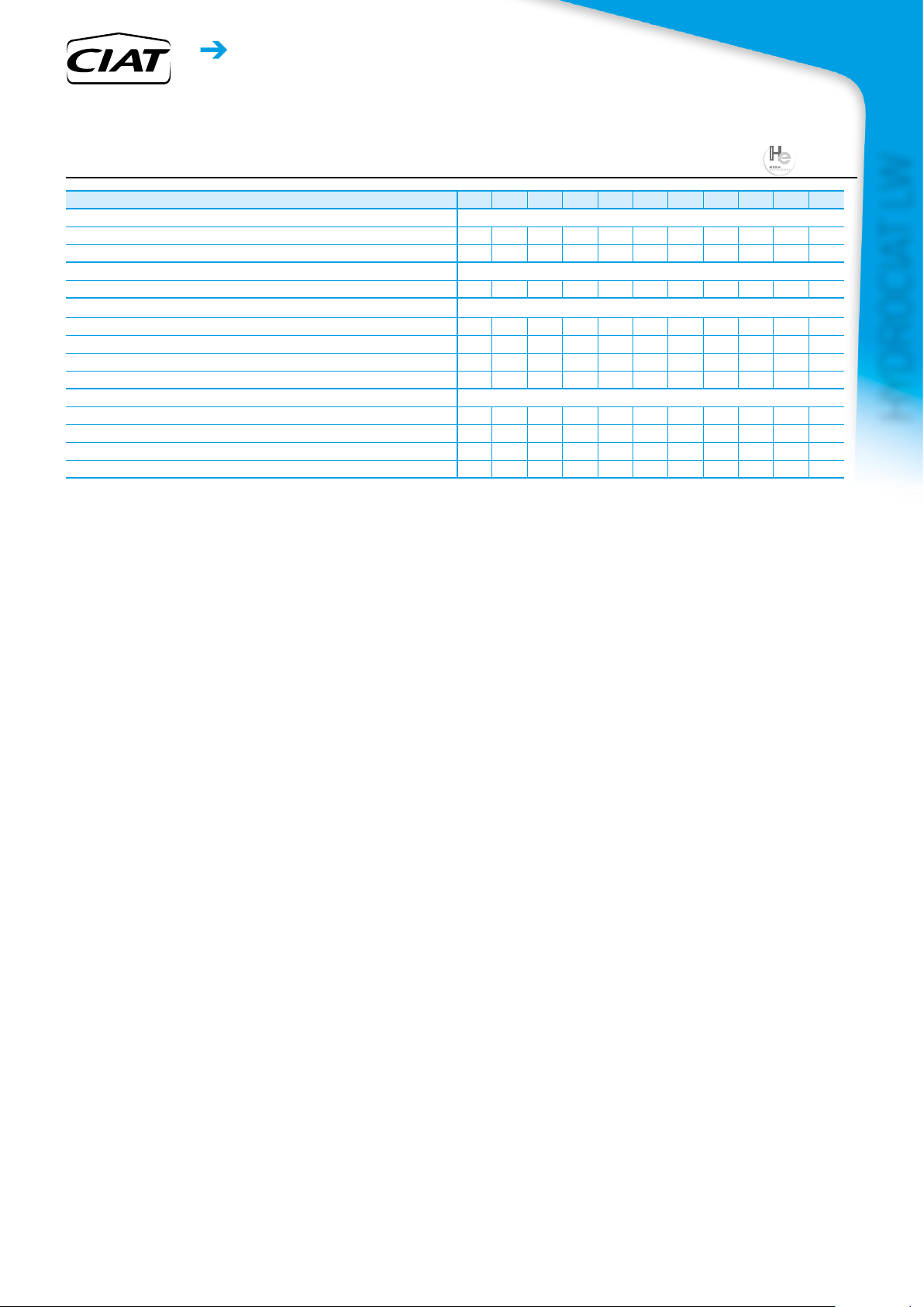
HYDROCIAT LW
high efficiency Unit technical chaRacteRistics
LW HE / LW HE + Heat pump application option 1328 1528 1928 2128 2328 2628 3028 3428 3828 4228 4628
Heating
Standard unit
Full load performances*
Standard unit
Seasonal energy
efciency**
Cooling
Standard unit
Full load performances*
Standard unit
Seasonal energy efciency**
Integrated Part Load Value IPLV.SI kW/kW 7,323 7,468 7,666 7,513 7,439 7,747 8,125 8,068 7,852 8,201 7,900
Sound levels - standard unit
Sound power level
Sound pressure level at 1 m
Sound levels - standard unit + Low noise level option
Sound power level
Sound pressure level at 1 m
Dimensions - standard unit
Length mm 3059 3059 3290 3290 3290 4730 4730 4730 4730 4832 4832
Width mm 936 936 1069 1069 1069 1039 1039 1162 1162 2129 2129
Height mm 1743 1743 1950 1950 1950 1997 1997 2051 2051 1562 1562
Operating weight
Compressors Semi-hermetic screw compressors, 50 r/s
Circuit A 1 1 1 1 1 1 1 1 1 1 1
Circuit B - - - - - 1 1 1 1 1 1
Refrigerant - standard unit R-134a
Circuit A
Circuit B
* In accordance with standard EN14511-3:2013.
** In accordance with standard EN14825:2016, average climate
HW1 Heating mode conditions: Evaporator entering/leaving water temperature 10°C/7°C, condenser entering/leaving water temperature
HW2 Heating mode conditions: Evaporator entering/leaving water temperature 10°C/7°C, condenser entering/leaving water temperature
CW1 Cooling mode conditions: Evaporator water entering/leaving temperature 12°C/7°C, condenser entering/leaving water temperature 30°C/35°C,
CW2 Cooling mode conditions: Evaporator water entering/leaving temperature 23°C/18°C, condenser entering/leaving water temperature
Ƞs heat
30/35°C
Ƞs cool
12/7°C
SEPR
12/7°C
IPLV.SI Calculations according to standard performances AHRI 551-591 (SI)
(1) In dB ref=10
(2) In dB ref 20µPa, (A) weighting. Declared dualnumber noise emission values in accordance with ISO 4871 (with an associated uncertainty of
(3) Weight shown is guideline only. Please refer to the unit nameplate
(1)
(1)
(3)
& SCOP
& SEER
Values calculated in accordance with EN14825:2016
30/35°C
12/7°C
Nominal capacity kW 596 676 860 923 1009 1216 1352 1545 1705 1890 2048
HW1
COP kW/kW 6,48 6,39 6,58 6,36 6,35 6,42 6,35 6,38 6,14 6,46 6,35
Nominal capacity kW 583 662 842 904 982 1191 1320 1509 1663 1846 1989
HW2
COP kW/kW 4,91 4,84 4,97 4,80 4,85 4,90 4,86 4,89 4,71 4,89 4,87
SCOP
30/35°C
HW1
ŋs heat
30/35°C
P
rated
Nominal capacity kW 509 577 737 786 861 1039 1157 1323 1452 1626 1756
CW1
EER kW/kW 5,71 5,65 5,83 5,62 5,65 5,73 5,78 5,80 5,58 5,87 5,79
Eurovent class - A A A A A A A A A A A
Nominal capacity kW 616 705 936 1007 1088 1251 1395 1683 1926 2062 2215
CW2
EER kW/kW 6,85 6,81 7,24 7,00 6,92 6,85 6,83 7,14 7,10 7,21 7,00
Eurovent class - A A A A A A A A A A A
SEER
ŋs cool
SEPR
(2)
(2)
30°C/35°C, evaporator and condenser fouling factor 0 m2. k/W
40°C/45°C, evaporator and condenser fouling factor 0 m2. k/W
evaporator and condenser fouling factor 0 m².K/W
30°C/35°C, evaporator and condenser fouling factor 0 m².K/W
Values calculated in accordance with EN14825:2016
Bold values compliant to Ecodesign regulation: (EU) No 2016/2281 for Comfort application
+/-3dB(A)). Measured in accordance with ISO 9614-1 and certified by Eurovent.
+/-3dB(A)). For information, calculated from the sound power level Lw(A).
Comfort low temp. kWh/kWh 5,79 5,82 6,60 6,36 6,03 6,75 7,17 7,00 6,83 7,27 7,25
12/7°C
12/7°C
Process high temp. kWh/kWh 7,87 7,91 8,13 7,69 7,53 7,88 7,99 8,16 7,84 8,02 7,66
12/7°C
-12
W, (A) weighting. Declared dualnumber noise emission values in accordance with ISO 4871 (with an associated uncertainty of
kWh/kWh 6,27 6,33 6,50 6,27 6,27 6,43 6,37 6,22 6,01 6,38 6,29
% 243 245 252 243 243 249 247 241 232 247 244
kW 706 802 1019 1093 1196 1441 1600 1831 2021 2241 2428
% 229 230 261 251 238 267 284 277 270 288 287
dB(A) 99 99 99 99 99 102 102 102 102 102 102
dB(A) 82 82 81 81 81 83 83 83 83 83 83
dB(A) 96 96 96 96 96 99 99 99 99 99 99
dB(A) 78 78 78 78 78 80 80 80 80 80 80
kg 2981 3020 3912 3947 3965 6872 6950 7542 7752 10910 10946
kg 130 130 180 175 170 120 120 130 130 240 250
teqCO
teqCO
186 186 257 250 243 172 172 186 186 343 358
2
kg - - - - - 120 120 150 130 240 250
- - - - - 172 172 215 186 343 358
2
12
Eurovent certied values
HEAT PUMPS - AIR CONDITIONING - REFRIGERATION - AIR HANDLING - HEAT EXCHANGE - NA 18.752 B
Water chillers
H
Heat pump
high efficiency Unit technical chaRacteRistics
LW HE / LW HE + Heat pump application option 1328 1528
Oil - standard unit SW220
Circuit A l 32 32 36 36 36 32 32 36 36 36 36
Circuit B l - - - - - 32 32 32 36 36 36
Capacity control Connect Touch, electronic expansion valves (EXV)
Minimum capacity
Evaporator Shell and tube ooded type
Water volume l 101 101 154 154 154 293 293 321 321 473 473
Water connections (Victaulic) in 6 6 8 8 8 8 8 8 8 10 10
Drain and vent connections (NPT) in 3/8 3/8 3/8 3/8 3/8 3/8 3/8 3/8 3/8 3/8 3/8
Max. water-side operating pressure kPa 1000 1000 1000 1000 1000 1000 1000 1000 1000 1000 1000
Condenser Shell and tube type
Water volume l 103 103 148 148 148 316 316 340 340 623 623
Water connections (Victaulic) in 6 6 8 8 8 8 8 8 8 10 10
Drain and vent connections (NPT) in 3/8 3/8 3/8 3/8 3/8 3/8 3/8 3/8 3/8 3/8 3/8
Max. water-side operating pressure kPa 1000 1000 1000 1000 1000 1000 1000 1000 1000 1000 1000
(4) Minimum unit capacity corresponds to a physical state of the unit and is given for indication only. The actual capacity at this stage depends on operating conditions.
(4)
% 15 15 15 15 15 10 10 10 10 10 10
1928
2128 2328 2628 3028 3428 3828 4228 4628
HYDROCIAT LW
HEAT PUMPS - AIR CONDITIONING - REFRIGERATION - AIR HANDLING - HEAT EXCHANGE - NA 18.752 B
13
Water chillers
Heat pump
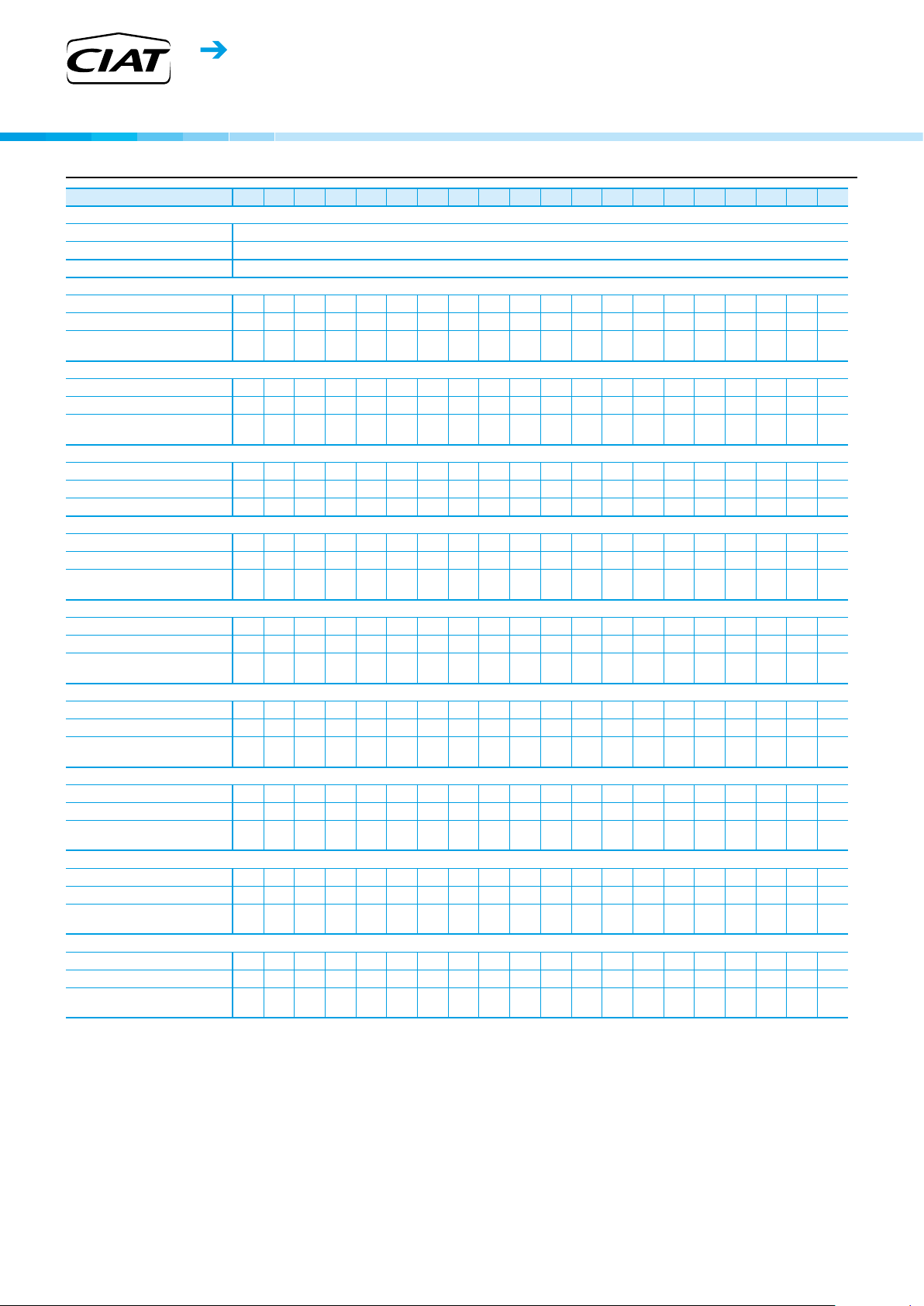
electRical Data notes foR stanDaRD Units
HYDROCIAT LW
LW ST 708 858
Power circuit
Nominal voltage V-ph-Hz 400-3-50
Voltage range V 360-440
Control circuit 24 V via the built-in transformer
Nominal start-up current
Circuit A A 233 233 303 414 414 414 414 587 587 587 587 414 414 414 587 587 587 587 587 587
Circuit B A - - - - - - - - - - - 414 414 414 414 587 587 587 587 587
Single power connection
point option
Maximum start-up current
Circuit A A 233 233 303 414 414 414 414 587 587 587 587 414 414 414 587 587 587 587 587 587
Circuit B A - - - - - - - - - - - 414 414 414 414 587 587 587 587 587
Single power connection
point option
Cosine phi
(3)
Nominal
(4)
Maximum
Total harmonic distortion
Maximum power input*
Circuit A kW 76 89 97 128 135 151 151 184 200 223 223 150 151 151 184 184 200 223 223 223
Circuit B kW - - - - - - - - - - - 135 151 151 151 184 200 223 202 223
Single power connection
point option
Nominal input current
Circuit A A 84 96 113 136 144 162 162 193 214 232 232 162 162 162 193 193 214 232 232 232
Circuit B A - - - - - - - - - - - 144 162 162 162 193 214 232 214 232
Single power connection
point option
Maximum input current (Un)*
Circuit A A 123 145 160 206 217 242 242 295 317 351 351 242 242 242 295 295 317 351 351 351
Circuit B A - -
Single power connection
point option
Maximum input current (Un -10%)
Circuit A A 138 162 178 218 230 260 260 304 340 358 358 260 260 260 304 304 340 358 358 358
Circuit B A - - - - - - - - - - - 230 260 260 260 304 340 358 340 358
Single power connection
point option
Maximum input power with condensing temperature limitation option*
Circuit A kW 67 79 87 114 118 133 134 173 183 205 205 133 133 133 173 173 183 207 207 207
Circuit B kW - - - - - - - - - - - 11 8 133 133 133 173 183 207 185 207
Single power connection
point option
Maximum input current (Un) with condensing temperature limitation option*
Circuit A A 109 129 142 183 191 212 212 278 290 325 325 212 212 212 278 278 290 325 325 325
Circuit B A - - - - - - - - - - - 191 212 212 212 278 290 325 290 325
Single power connection
point option
(1)
A - - - - - - - - - - - 558 574 574 747 780 801 819 819 819
(2)
A - - - - - - - - - - - 631 656 656 829 882 904 938 938 938
0.83 0.85 0.83 0.87 0.88 0.89 0.89 0.88 0.89 0.90 0.90 0.88 0.89 0.89 0.88 0.88 0.89 0.9 0.9 0.9
(4)
0.89 0.89 0.88 0.90 0.90 0.91 0.91 0.90 0.91 0.92 0.92 0.90 0.91 0.91 0.90 0.90 0.91 0.92 0.92 0.92
% 0 0 0 0 0 0 0 0 0 0 0 0 0 0 0 0 0 0 0 0
kW - - - - - - - - - - - 284 301 301 334 367 399 447 425 447
(3)
A - - - - - - - - - - - 306 324 324 355 386 427 464 446 464
A - - - - - - - - - - - 459 484 484 537 590 634 702 668 702
A - - - - - - - - - - - 490 520 520 564 608 680 716 698 716
kW - - - - - - - - - - - 251 265 265 305 346 365 414 391 414
A - - - - - - - - - - - 403 424 424 490 556 580 650 615 650
1008 1300 1302 1500 1508 1900 2100 2300 2308 2800 3000 3008 3400 3800 4200 4600 4408 4608
- - - - - - - - - 217 242 242 242 295 317 351 317 351
(4)
(1) Instantaneous start-up current (maximum operating current of the smallest compressor(s) + locked rotor current or reduced start-up current of the largest compressor).
Values obtained at standard Eurovent unit operating conditions: evaporator entering/leaving water temperature = 12°C/7°C, condenser entering/leaving water
temperature = 30°C/35°C.
(2) Instantaneous start-up current (maximum operating current of the smallest compressor(s) + locked rotor current or reduced start-up current of the largest compressor).
Values obtained at operation point with maximum unit power input.
(3) Values obtained at standard Eurovent unit operating conditions: evaporator entering/leaving water temperature = 12°C/7°C, condenser entering/leaving water
temperature = 30°C/35°C.
(4) Values obtained at operation point with maximum unit power input.
* Values obtained in operation with maximum unit power input. Values given on the unit name plate.
14
HEAT PUMPS - AIR CONDITIONING - REFRIGERATION - AIR HANDLING - HEAT EXCHANGE - NA 18.752 B
 Loading...