

CIAT Ereba He Series Instruction Manual

10195
05 - 2019
Instruction manual
EREBA He
Heat Pumps
Inverter Reversible Air-to-Water

CONTENTS
ACRONYMS AND LEGEND .................................................................................5
Acronyms .......................................................................................................................5
Control Configuration Legend ..........................................................................................5
Standard installation Legend ...........................................................................................6
1 - INTRODUCTION ..............................................................................................7
1.1 - Introduction ..............................................................................................................7
1.2 - Safety.......................................................................................................................7
1.3 - Preliminary checks ..................................................................................................13
1.4 - Dimensions and clearance for EREBA He units ......................................................14
1.5 - Physical data and electrical data of EREBA He units ..............................................16
1.6 - Accessories ............................................................................................................18
2 - INSTALLATION OF UNIT ...............................................................................19
2.1 - General ...................................................................................................................19
2.2 - Moving and placing the unit ....................................................................................19
2.3 - Water connections ..................................................................................................21
2.4 - Electrical connections .............................................................................................26
2.5 - Water flow rate control ............................................................................................28
2.6 - Commissioning modes ...........................................................................................32
2.7 - Check before start the unit ......................................................................................32
3 - INSTALLATION OF SYSTEM .........................................................................33
3.1 - General customer electrical connection on terminal block ......................................33
3.2 - First step of configuration: Setting the time and day ................................................34
3.3 - Second step of configuration: Parameter menu ......................................................35
3.4 - Installation with electrical booster heaters ..............................................................36
3.5 - Installation with DHW production ............................................................................39
3.6 - Installation with boiler ..............................................................................................43
3.7 - Installation with DHW and pool heating production, boiler and buffer tank ..............46
3.8 - Master / Slave installation .......................................................................................49
3.9 - Unit with remote user interface................................................................................54
3.10 - Additional OAT sensor ..........................................................................................56
3.11 - IAT sensor .............................................................................................................56
4 - OPERATION ...................................................................................................58
4.1 - Unit range - EREBA He ...........................................................................................58
4.2 - Operating modes ...................................................................................................58
4.3 - Major system components ......................................................................................72
EREBA He
EN-2

CONTENTS
5 - MAINTENANCE ..............................................................................................75
5.1 - Standard maintenance ............................................................................................75
5.2 - Tightening torques for the main electrical connections ...........................................77
5.3 - Air heat exchanger ..................................................................................................77
5.4 - Water heat exchanger maintenance ........................................................................77
5.5 - Unit maintenance ....................................................................................................77
5.6 - Refrigerant volume ..................................................................................................77
5.7 - Characteristics of R-410A .......................................................................................78
6 - ALARM DESCRIPTION ..................................................................................79
6.1 - Inverter board alarm codes (only for 11-15 kW 1Ph or 3Ph units) ...........................79
6.2 - Alarm listing ............................................................................................................80
7 - PARAMETERS OVERVIEW ............................................................................83
7.1 - Parameters list ........................................................................................................83
7.2 - Description of customized DI/DO configurations .....................................................90
8 - START-UP CHECKLIST FOR EREBA He HEAT PUMPS (USE FOR JOB FILE) .. 91
8.1 - General information ................................................................................................91
8.2 - Available options and accessories ..........................................................................91
8.3 - Checks before start of unit ......................................................................................92
8.4 - Checks during operation of unit ..............................................................................92
8.5 - Maintenance checks ...............................................................................................93
TABLES CONTENT
Table 1: Minimum and maximum wire section (per phase) for connection to EREBA He
units ..................................................................................................................27
Table 2: Steps to clean, purge, and define a flow rate for hydraulic circuit .......................29
Table 3:
Table 4: Different operating modes .................................................................................59
Table 5: Possible switches to install on system ...............................................................60
Table 6: Different configurations of pump .......................................................................68
Table 7: Different control logic for main pump .................................................................69
Table 8: Different control logic for additional pump ..........................................................69
Table 9: Alarms listing .....................................................................................................80
Actions in WUI parameter menu or Service tools to activate the cleaning purge and
control of flow rate for hydraulic circuit ...................................................................... 29
GRAPHICS CONTENT
Graphic 1: Available static pressure for 5 to 15 kW units with hydraulic module ..............31
EN-3
EREBA He

FIGURES CONTENT
Figure 1: Transport configuration .....................................................................................19
Figure 2: Offloading configuration ...................................................................................19
Figure 3 : How to remove front panel for 11 & 15 kW units ..............................................20
Figure 4 : How to remove front panel for 5 & 7 kW units ..................................................20
Figure 5 : Opening cable knockouts ................................................................................21
Figure 6: Water connection on unit ..................................................................................23
Figure 7: Typical diagram of the hydraulic circuit with the hydraulic module ....................24
Figure 8: Hydraulic module equipped with variable speed single pump low available pressure
with expansion tank ........................................................................................25
Figure 9: Power connection with Main Switch .................................................................26
Figure 10: Customer electrical connection on terminal block .........................................33
Figure 11: Password screen ............................................................................................35
Figure 12: Standard installation with electrical booster heaters.......................................37
Figure 13: Electrical connection on terminal block for electrical booster heaters ............38
Figure 14: Standard installation with DHW production ....................................................40
Figure 15: Electrical connection on terminal block for DHW production ..........................41
Figure 16: Standard installation with boiler ......................................................................44
Figure 17: Electrical connection on terminal block for boiler............................................45
Figure 18: Standard installation with DHW production, pool heating production ans space
heating (floor heating or radiator/fan coils) .....................................................47
Figure 19: Electrical connection on terminal block for DHW, speace heating, pool heating
production and boiler ......................................................................................48
Figure 20: Standard installation with Master / Slave (example with 3 slaves) ..................50
Figure 21: Electrical connection on terminal block for Master / Slave installation ............51
Figure 22: WUI screen for Slave 1 ...................................................................................54
Figure 23: Electrical connection of remote interface .......................................................54
Figure 24: Electrical connection of additional OAT sensor and IAT sensor ......................56
Figure 25: Winter position for unit with hydraulic module .................................................65
Figure 26: Operation of booster and backup ...................................................................69
Figure 27: Activation and configuration for drying mode .................................................71
EREBA He
EN-4
ACRONYMS AND LEGEND
Acronyms
IAT
BPHE
CHWS
DHW
EHS
EWT
FCU
LWT
NHC
OAT
PMV
SHC
TR
UFC
UFH
WUI
Control Configuration Legend
Indoor Air Temperature
Brazed Plate Heat Exchanger
Chiller Water System
Domestic Hot Water
Electric Heater Stage
Entering Water Temperature
Fan Coil Unit
Leaving Water Temperature
New Hydraulic Control (refer to wiring diagram 'Main control card')
Outdoor Air Temperature
Pulse Modulating Valve
Space Heating / Cooling Control
Refrigerant Temperature
Underfloor Cooling
Underfloor Heating
User Interface (Wall-mounted User Interface)
Number of
parameter
Steps Table Par. Designation Description Range Default Ex. Unit
Different steps to be done
to configure the unit
Possible to configure by direct access on WUI. Refer to WUI end user Manual.
Check to be done
Advanced Configuration Level (for basic operation no need to modify the setting)
Name of the table to be
used in Customer Com. Bus
Name of parameter to be
used in Customer Com. Bus
Description of different value
which can take the parameter
Range of
parameter
Value by Default
of parameter
Value given in example and
adapted at the described case
Unit of parameter
EN-5
EREBA He

ACRONYMS AND LEGEND
Standard installation Legend
Label Symbol Designation Notes
-
-
-
-
-
-
Acc
Acc
Add EXP-T
- Boiler Boiler used to boost or backup the heat pump for comfort
EH1 & EH2
EH3
EH3
Device Field supplied
Accessory Field mounted
Option Factory mounted
Balancing valve
Stop valve Field supplied
Automatic Air vent
Additional expansion tank
Electrical Heater (1 or 2)
DHW-Electrical Heater Backup (1 stage)
Field supplied
Balancing to adjust the water flow rate
Field supplied
Automatic air vent(s) on highest position in the loop
Field supplied
Additional expansion tank depending the total water in the
loop contend - taking in account the expansion tank (XXL)
embedded in hydraulic module
Electrical heaters up to two with a max. stages up to 3
Used to boost or backup the heat pump for comfort
Domestic Hot Water Electrical Heater - one stage used
to backup DHW (when condtions are out of heat pump
map)
DHW-T
DHW-S
DHW-V
add_pmp
De-Coupling
Tank
Backup-EH
-
HTSS
B
AB
EH1 EH2
HTSS
T>Tmax
Domestic Hot Water - Tank Field supplied
Domestic Hot Water - Sensor
A
Domestic Hot Water - Valve or Diverting valve
Additional Water Pump
De-Coupling Tank
Backup electrical heater
Flexible
High Temperature Safety Switch
Accessory to mount on top of the DHW-Tank
Measure DHW-Temperature
Accessory to be field mounted, it will position the valve
to send either to comfort loop or DHW-T, the processed
water
Field Supplied, it is used for comfort loop as a secondary
loop
Field Supplied, it is used to connect different water loop
rates as well as to receive the boiler loop
Field Supplied, it is used for comfort loop as a Booster
Heater (HP+EH) or Backup (EH only) when HP is out of
the map.
Field supply, it is used to lower vibrations transmissions
if necessary
Field supplied, use to stop system when UFH max, water
temperature is triggered
EREBA He
EN-6

1 - INTRODUCTION
1.1 - Introduction
Prior to the initial start-up of the EREBA
He units, the people involved should be
thoroughly familiar with these instructions
and technical data for the installation.
This appliance can be used by children
aged from 8 years and above and
persons with reduced physical, sensory or
mental capabilities or lack of experience
and knowledge if they have been given
supervision or instruction concerning use of
The EREBA He outdoor systems are
designed to provide a very high level of
the appliance in a safe way and understand
the hazards involved.
safety and reliability making installation,
start-up, operation and maintenance easier
and more secure. They will provide safe and
reliable service when operated within their
application range.
They are designed for an operating life of 15
years by assuming a 75% utilisation factor;
that is approximately 100,000 operating
hours.
The procedures in this manual are
arranged in the sequence required for
machine installation, start-up, operation and
maintenance.
Children shall not play with the appliance.
Cleaning and user maintenance shall not be
made by children without supervision.
Do not remove the pallet or the packaging
until the unit is in its nal position. These
units can be moved with a fork lift truck, as
long as the forks are positioned in the right
place and direction on the unit.
The units can also be lifted with slings (refer
to Figure 1 and 2).
Use slings with the correct capacity, and
always follow the lifting instructions on the
certied drawings supplied for the unit.
Be sure you understand and follow the
procedures and safety precautions contained
in the instructions supplied with the machine,
as well as those listed in this guide, such as:
protective clothing such as gloves, safety
glasses, safety shoes and appropriate tools,
and suitable qualifications (electrical, air
conditioning, local legislation).
To find out, if these products comply with
European directives (machine safety, low
voltage, electromagnetic compatibility,
equipment under pressure, etc.) check the
declarations of conformity for these products.
Safety is only guaranteed, if these
instructions are carefully followed. If this
is not the case, there is a risk of material
deterioration and injuries to personnel.
DO NOT COVER ANY PROTECTION
DEVICES.
This applies to fuse plugs and relief valves
(if used) in the refrigerant or heat transfer
medium circuits. Check if the original
protection plugs are still present at the
valve outlets. These plugs are generally
made of plastic and should not be used.
If they are still present, please remove
them. Install devices at the valve outlets or
1.2 - Safety
1.2.1 - Installation safety considerations
After the unit has been received, and before it
is started up, it must be inspected for damage.
Check that the refrigerant circuits are intact,
especially that no components or pipes have
shifted or been damaged (e.g. following a
drain piping that prevent the penetration of
foreign bodies (dust, building debris, etc.)
and atmospheric agents (water can form
rust or ice). These devices, as well as the
drain piping, must not impair operation and
not lead to a pressure drop that is higher
than 10% of the control pressure.
shock). If in doubt, carry out a leak tightness
check. If damage is detected upon receipt
and before signature, immediately file a claim
with the shipping company.
EN-7
EREBA He

1 - INTRODUCTION
Control:
When the unit is subjected to re, the
uid may then be decomposed into toxic
residues when subjected to the ame :
- Stay away from the unit.
- Set up warnings and
recommendations for personnel in
charge to stop the fire.
components are given on the nameplate or
in the required documentation, supplied with
the products.
The units are intended to be stored and
operate in an environment where the
ambient temperature must not be less than
the lowest allowable temperature indicated
on the nameplate.
- Fire extinguishers appropriate to
the system and the refrigerant type
must be easily accessible.
Do not introduce signicant static or
dynamic pressure with regard to the
operating pressures used during operation
All precautions concerning handling of
refrigerant must be observed in accordance
or for tests in the refrigerant circuit or in the
heat exchange circuits.
with local regulations.
NOTES:
Accumulation of refrigerant in an enclosed
space can displace oxygen and cause
asphyxiation or explosions.
Monitoring during operation, re-
qualication, re-testing, exemption from
retesting:
Inhalation of high concentrations of
vapour is harmful and may cause heart
irregularities, unconsciousness, or death.
Vapour is heavier than air and reduces the
amount of oxygen available for breathing.
These products cause eye and skin
irritation. Decomposition products can be
hazardous.
Short-circuit power
This equipment complies with EN 610003-12 provided that the short-circuit power
Ssc is greater than or equal to 1,6 MVA
at the interface point between the user’s
supply and the public system. It is the
responsibility of the installer or user of
the equipment to ensure, by consultation
with the distribution network operator if
necessary, that the equipment is connected
only to a supply with a short-circuit power
Ssc greater than or equal to 1,6 MVA.
1.2.2 - Equipment and components
under pressure
These products incorporate equipment or
components under pressure, produced by
manufacturers. We recommend that you
consult your appropriate national trade
association or the owner of the equipment
or components under pressure (declaration,
re-qualification, retesting, etc.). The
characteristics of this equipment/these
● Follow local regulations on the monitoring
of pressure-containing equipment.
● The user or the operator is usually
requested to create and maintain a
monitoring and maintenance register.
● In absence of regulation or in addition to
the regulations, follow the guidance in
ISO 5149.
● Follow the local professional
recommendations, whenever they exist.
● Regularly monitor the surface of the
components to detect cavernous
corrosion. To do this check an uninsulated
part of the pressure vessel or at a joint in
the insulation.
● Regularly check for possible presence of
impurities (e.g. silicon grains) in the heat
exchange fluids. These impurities can
cause wear and/or pitting corrosion.
● Filter the heat exchange fluid.
● The reports of the periodical checks by
the user or the operator must be included
in the monitoring and maintenance
register.
EREBA He
EN-8

1 - INTRODUCTION
Repair:
Any repair or modication of a pressure
vessel is prohibited.
Only the replacement of the vessel by
an original part from the manufacturer is
allowed. In this case, the replacement must
be carried out by a qualied technician. The
replacement of the vessel must be entered
in the monitoring and maintenance register.
Recycling:
The pressure equipment can be recycled in
whole or in part. After use they may contain
protective clothing.
Never work on a unit that is still energized.
Never work on any of the electrical
components, until the general power supply
to the unit has been cut.
If any maintenance operations are carried
out on the unit, lock the power supply
circuit in the open position and secure the
machine upstream with a padlock.
If the work is interrupted, always ensure
that all circuits are still de-energized before
resuming the work.
refrigerant vapours and oil residue. Some
parts are painted.
1.2.3 - Maintenance safety
considerations
Professional technicians working on the
electric or refrigeration components must be
authorized, trained and fully qualified to do
so.
All refrigerant circuit work must be carried out
by a trained person, fully qualified to work
on these units. He must have been trained
and be familiar with the equipment and the
installation. All welding operations must be
carried out by qualified specialists.
The units use high-pressure R-410A
refrigerant (the unit operating pressure
is above 40 bar, the pressure at 35°C air
temperature is 50% higher than for R-22).
Special equipment must be used when
working on the refrigerant circuit (pressure
gauge, charge transfer, etc.).
Do not clean the unit with hot water or
steam. This may cause a pressure increase
of the refrigerant.
Any manipulation (opening or closing)
of a shut-off valve must be carried out
by a qualied and authorised technician,
observing applicable standards (e.g. during
draining operations). The unit must be
switched off while this is done.
Even if the unit has been switched off,
the power circuit remains energized,
unless the unit or customer circuit
disconnect switch is open. Refer
to the wiring diagram for further
details. Attach appropriate safety
labels. When working in a fan area,
specically if the grilles have to be
removed, isolate the power supply to
the fans to prevent their operation.
The variable frequency drives
(VFD) tted to the units have circuit
capacitors whose discharge time is
ve (5) minutes after disconnecting
the power supply.
Therefore, after disconnecting the
power supply of the control box, wait
for 5 minutes before access it.
Before any intervention, verify that
there is no voltage present at any
accessible conducting parts of the
power circuit.
Moreover be careful of contact with
zones at hot temperature inside
the unit, which can exist after the
operation of unit (refrigerant and
electronic parts).
During any handling, maintenance and
service operations the qualied technician
working on the unit must be equipped with
safety gloves, safety glasses, shoes and
EN-9
EREBA He
1 - INTRODUCTION
It is recommended to install an
indicating device to show if part of the
refrigerant has leaked from the valve.
The presence of oil at the outlet orice
is a useful indicator that refrigerant
has leaked. Keep this orice clean to
ensure that any leaks are obvious. The
calibration of a valve that has leaked
is generally lower than its original
calibration. The new calibration may
affect the operating range. To avoid
nuisance tripping or leaks, replace or
re-calibrate the valve.
OPERATING CHECKS:
● IMPORTANT INFORMATION
REGARDING THE REFRIGERANT USED:
This product contains uorinated
greenhouse gas covered by the Kyoto
protocol.
Refrigerant type: R-410A
6. The gas recovery for recycling,
regeneration or destruction is at
customer charge.
7. Periodic leak tests have to be
carried out by the customer or by
third parties. The EU regulation
set the periodicity here after:
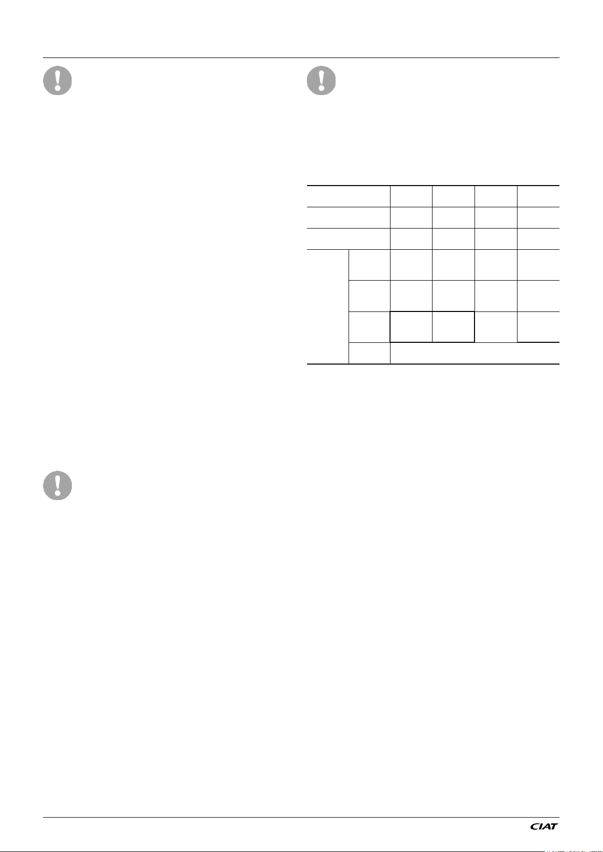
System WITHOUT
leakage detection
System WITH leakage
detection
Refrigerant charge/circuit
(CO
equivalent)
2
R134A
(GWP 1430)
R407C
(GWP 1774)
R410A
(GWP 2088)
HFO’s:
R1234ze
Refrigerant charge/
Circuit (kg)
(1) From 01/01/2017, units must be equipped with a leakage detection system
No Check 12 Months 6 Months 3 Months
No Check 24 Months 12 Months 6 Months
< 5 Tons
Charge <
3.5 kg
Charge <
2.8 kg
Charge <
2.4 kg
No requirement
5 ≤ Charge
< 50 Tons
3.5 ≤
Charge <
34.9 kg
2.8 ≤
Charge <
28.2 kg
2.4 ≤
Charge <
23.9 kg
50 ≤ Charge
< 500 Tons
34.9 ≤
Charge <
349.7 kg
28.2 ≤
Charge <
281.9 kg
23.9 ≤
Charge <
239.5 kg
Charge >
500 Tons(1)
Charge >
349.7 kg
Charge >
281.9 kg
Charge >
239.5 kg
Global Warming Potential (GWP): 2088
Periodic inspections for refrigerant leaks
may be required depending on European or
local legislation. Please contact your local
dealer for more information.
1. Any intervention on the refrigerant
circuit of this product should be
performed in accordance with the
applicable legislation. In the EU,
the regulation is called F-Gas,
N°517/2014.
2. Ensure that the refrigerant is
never released to the atmosphere
during installation, maintenance
or equipment disposal.
3. The deliberate gas release into the
atmosphere is not allowed.
4. If a refrigerant leak is detected,
ensure that it is stopped and
repaired as quickly as possible.
5. Only a qualified and certified
personnel can perform installation
operations, maintenance,
refrigerant circuit leak test as well
as the equipment disposal and the
refrigerant recovering.
8. A logbook must be established for
equipments subject to periodic leak
tests. It should contain the quantity
and the type of fluid present within the
installation (added and recovered), the
quantity of recycled fluid, regenerated
or destroyed, the date and output of the
leak test, the designation of the operator
and its belonging company, etc.
9. Contact your local dealer or installer if
you have any questions.
Protection device checks:
● If no national regulations exist, check the
protection devices on site in accordance
with standard ISO 5149: every five years
for external relief valves.
NOTE: The following statements are only
indicated if a pressure switch is available
on the unit.
The company or organisation that conducts
a pressure switch test shall establish and
implement a detailed procedure to fix:
- Safety measures
- Measuring equipment calibration
- Validating operation of protective
devices
EREBA He
EN-10
1 - INTRODUCTION
- Test protocols
- Recommissioning of the equipment.
Consult Service for this type of test. The
manufacturer mentions here only the principle
of a test without removing the pressure switch:
- Verify and record the setpoints of
pressure switches and relief devices
(valves and possible rupture discs)
- Be ready to switch-off the main
disconnect switch (on the unit or on the
installation) of the power supply if the
pressure switch does not trigger (avoid
over-pressure)
- Connect a calibrated pressure gauge
(with Schrader female port of ½ UNF)
Inspect the protection devices such
as valves.
If the machine operates in a corrosive
environment, inspect the protection
devices more frequently.
Check regularly for leaks and repair
immediately. Ensure regularly that
the vibration levels remain acceptable
and close to those at the initial unit
start-up.
Before opening a refrigerant circuit,
transfer the refrigerant to bottles
specically provided for this purpose
and consult the pressure gauges.
Change the refrigerant after an
equipment failure, following a
procedure such as the one described
in NF E29-795 or carry out a refrigerant
analysis in a specialist laboratory.
If the refrigerant circuit remains
open after an intervention (such as a
component replacement, etc.):
● Seal the openings if the duration is
less than a day
● If more than 1 day, charge the
circuit with oxygen free nitrogen
(inertia principle).
The objective is to prevent penetration
of atmospheric humidity and the
resulting corrosion.
1.2.4 - Repair safety considerations
All installation parts must be maintained by
the personnel in charge to avoid deterioration
and injury. Faults and leaks must be repaired
immediately. The authorized technician must
have the responsibility to repair the fault
immediately. After each unit repair check
the operation of the protection devices and
create a 100% parameter operation report.
Comply with the regulations and
recommendations in unit and HVAC
installation safety standards, such as: ISO
5149.
If the supply cord is damaged, it must be
replaced by the manufacturer, its service
agent or similarly qualied persons in order
to avoid a hazard.
RISK OF EXPLOSION
Never use air or a gas containing oxygen
during leak tests to purge lines or to
pressurise a machine. Pressurised air
mixtures or gases containing oxygen can
be the cause of an explosion. Oxygen reacts
violently with oil and grease.
Only use dry nitrogen for leak tests, possibly
with an appropriate tracer gas.
If the recommendations above are not
observed, this can have serious or even fatal
consequences and damage the installation.
Never exceed the specied maximum
operating pressures. Verify the allowable
maximum high- and low-side test pressures
by checking the instructions in this manual
and the pressures given on the unit name
plate.
Do not unweld or amecut the refrigerant
lines or any refrigerant circuit component
until all refrigerant (liquid and vapour) as well
as the oil have been removed from the heat
pump. Traces of vapour should be displaced
with dry nitrogen. Refrigerant in contact with
an open ame can produce toxic gases.
The necessary protection equipment
must be available, and appropriate re
extinguishers for the system and the
refrigerant type used must be within easy
reach.
EN-11
EREBA He

1 - INTRODUCTION
Do not siphon refrigerant.
Avoid spilling liquid refrigerant on skin
or splashing it into the eyes. Use safety
goggles and safety gloves. Wash any spills
from the skin with soap and water. If liquid
refrigerant enters the eyes, immediately
and abundantly ush the eyes with water
and consult a doctor.
The accidental releases of the refrigerant,
due to small leaks or signicant discharges
following the rupture of a pipe or an unexpected
release from a relief valve, can cause frostbites
and burns to personnel exposed. Do not
ignore such injuries. Installers, owners and
especially service technicians for these units
must:
- Seek medical attention before
treating such injuries.
- Have access to a first-aid kit,
especially for treating eye injuries.
We recommend to apply standard ISO 5149.
Never apply an open ame or live steam to a
refrigerant circuit. Dangerous overpressure
can result.
During refrigerant removal and storage
operations follow applicable regulations.
These regulations, permitting conditioning
and recovery of halogenated hydrocarbons
under optimum quality conditions for the
products and optimum safety conditions
for people, property and the environment
are described in standard NF E29-795.
The units must never be modied to add
refrigerant and oil charging, removal and
purging devices. All these devices are
provided with the units.
Be sure pressure is at 0 kPa and that the
unit has been shut-down and de-energised
before removing components or opening a
circuit.
Do not attempt to repair or recondition any
safety devices when corrosion or build-up
of foreign material (rust, dirt, scale, etc.) is
found within the valve body or mechanism.
If necessary, replace the device. Do not
install safety valves in series or backwards.
No part of the unit must be used
as a walkway, rack or support.
Periodically check and repair or if
necessary replace any component or
piping that shows signs of damage.
Do not step on refrigerant lines. The
lines can break under the weight and
release refrigerant, causing personal
injury.
Do not climb on a machine. Use a
platform, or staging to work at higher
levels.
Use mechanical lifting equipment
(crane, hoist, winch, etc.) to lift or
move heavy components. For lighter
components, use lifting equipment
when there is a risk of slipping or
losing your balance.
Refer to the certied dimensional drawings
for the units.
It is dangerous and illegal to re-use
disposable (non-returnable) cylinders or
attempt to rell them. When cylinders are
empty, evacuate the remaining gas pressure,
and move them to a designated place for
recovery. Do not incinerate.
Do not attempt to remove refrigerant circuit
components or ttings, while the machine
is under pressure or while it is running.
EREBA He
EN-12

1 - INTRODUCTION
Use only original replacement
parts for any repair or component
replacement. Consult the list of
replacement parts that corresponds
to the specication of the original
equipment.
Do not drain water circuits containing
industrial brines, without informing
the technical service department at
the installation site or a competent
body rst.
Close the entering and leaving water
shut-off valves and purge the unit
hydraulic circuit, before working
on the components installed on the
circuit (screen lter, pump, water
ow switch, etc.).
Periodically inspect all valves,
ttings and pipes of the refrigerant
and hydraulic circuits to ensure that
they do not show any corrosion or
any signs of leaks.
It is recommended to wear ear
defenders, when working near the
unit and the unit is in operation.
Always ensure you are using the
correct refrigerant type before
recharging the unit.
Charging any refrigerant other than
the original charge type (R-410A)
will impair machine operation and
can even lead to a destruction of
the compressors. The compressors
operate with R-410A and are charged
with asyntheticpolyol-ester oil.
Before any intervention on the
refrigerant circuit, the complete
refrigerant charge must be recovered.
1.3 - Preliminary checks
Check equipment received:
● Inspect the unit for damage or missing
parts. If damage is detected, or if shipment
is incomplete, immediately file a claim
with the shipping company.
● Confirm that the unit received is the one
ordered. Compare the name plate data
with the order.
● The name plate is attached to the unit in
two locations:
- on the outside on one of the unit sides
- on the inside.
● The unit name plate must include the
following information:
- Model number - size
- CE marking
- Serial number
- Year of manufacture, pressure and
leaktightness test date
- Fluid being transported
- Refrigerant used
- Refrigerant charge per circuit
- PS: Min./max. allowable pressure
(high and low pressure side)
- TS: Min./max. allowable temperature
(high and low pressure side)
- Unit leak test pressure
- Voltage, frequency, number of phases
- Maximum power input
- Unit net weight
● Confirm that all options ordered for on-site
installation have been delivered, and are
complete and undamaged.
The unit must be checked periodically, if
necessary removing the insulation (thermal,
acoustic), during its whole operating
life to ensure that no shocks (handling
accessories, tools, etc.) have damaged it.
If necessary, the damaged parts must be
repaired or replaced. See also chapter §5.
Maintenance.
EN-13
EREBA He
1 - INTRODUCTION
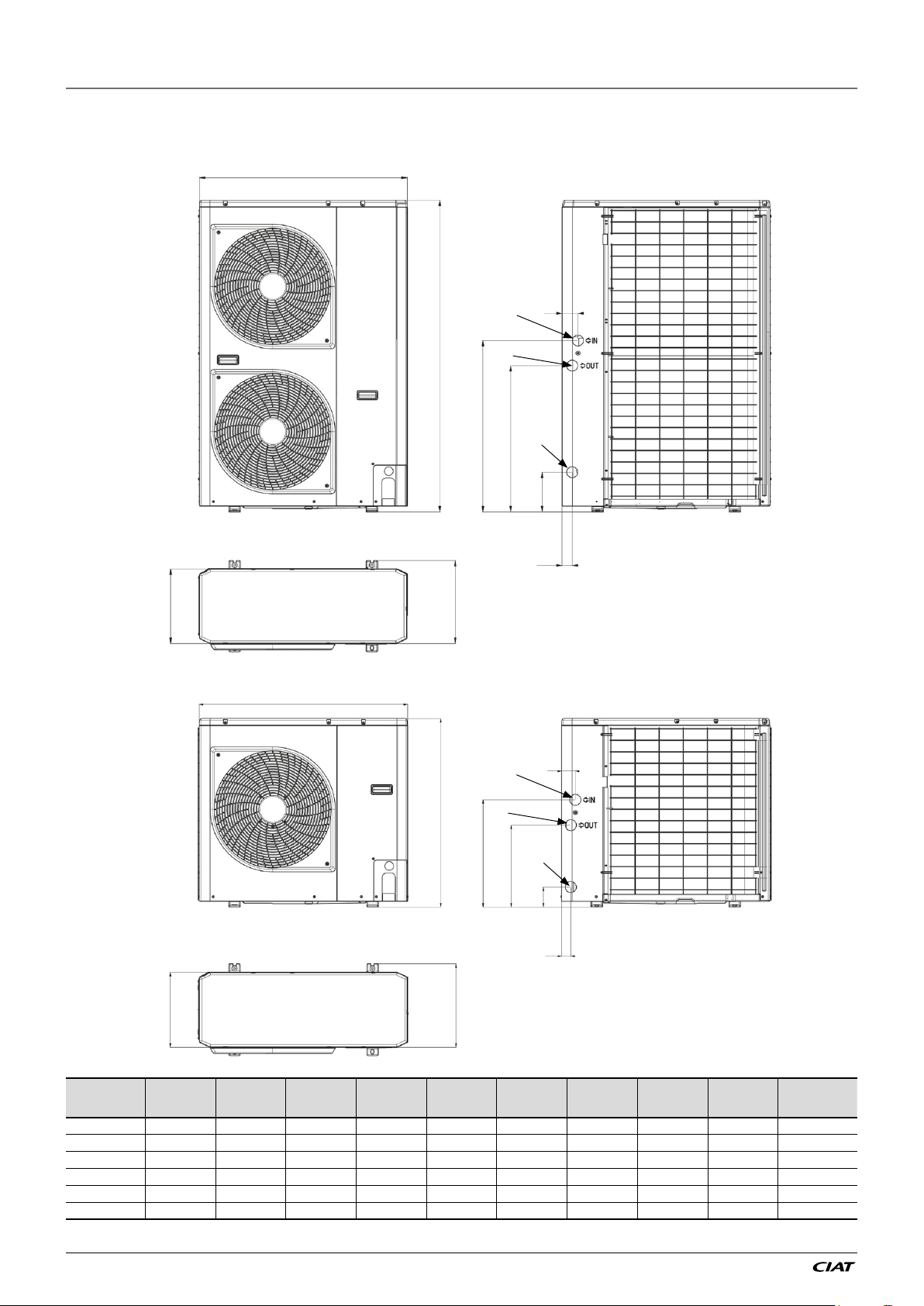
1.4 - Dimensions and clearance for EREBA He units
1.4.1 - Dimensions and location of hydraulic connections
A
L
a
B
C
A
D
b
G
F
c
E
H
L
a
B
C
EREBA He A B C D E F G H L masse (kg)
5_1Ph 908 821 326 350 87 356 466 40 60 57
7_1Ph 908 821 326 350 87 356 466 40 60 69
11_1Ph 908 1363 326 350 169 645 744 43 73 115
15_1Ph 908 1363 326 350 169 645 744 43 73 115
11_3Ph 908 1363 326 350 169 645 744 43 73 121
15_3Ph 908 1363 326 350 169 645 744 43 73 121
NOTE : Dimensions are given in mm
b
G
D
c
F
E
H
EREBA He
EN-14

1 - INTRODUCTION
1.4.2 - Clearances to ensure the correct air flow
The picture presents the minimal distances of the wall to ensure the correct air flow on air
(1)
heat exchanger
.
200
500
150
150
003051
150
1000
1000
500
1000
150150
300300
300
200
1000
200
300
(1) Anticipate different maintenance actions before to place the unit (access of different parts / opening of panel/ part replacement…)
300
1000
300
000200510001
200
EN-15
EREBA He
1 - INTRODUCTION
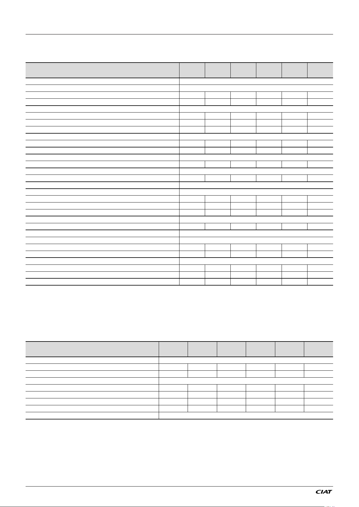
1.5 - Physical data and electrical data of EREBA He units
1.5.1 - Physical data EREBA He
EREBA He 5 (1Ph) 7 (1Ph) 11 (1Ph) 15 (1Ph) 11 (3Ph) 15 (3Ph)
Sound levels
Standard unit
Sound power level
Sound pressure level at 10 m
Dimensions
Length mm 908 908 908 908 908 908
Width mm 350 350 350 350 350 350
Height mm 821 821 1363 1363 1363 1363
Operating Weight
Standard unit kg 57 69 107 115 121 121
Compressors Rotary compressor 1 1 1 1 1 1
Refrigerant R410A
(1)
Charge
Capacity control
Minimum capacity
Condenser Grooved copper tubes, aluminium ns
Fans Axial type
Quantity 1 1 2 2 2 2
Maximum total air flow l/s 800 800 1800 1800 1800 1800
Maximum rotational speed rpm 560 660 820 820 820 820
Evaporator Brazed plate heat exchanger
Water volume l 1,7 2,3 4,4 4,4 4,4 4,4
Hydraulic module Circulator, relief valve, paddle ow switch, expansion tank
Circulator Centrifugal pump (variable speed)
Expansion tank volume l 2 2 3 3 3 3
Max. water-side operating pressure with hydraulic module
Water connections
Inlet diameter (BSP GAS) inch 1 1 1 1 1 1
Outlet diameter (BSP GAS) inch 1 1 1 1 1 1
Chassis paint colour Colour code: RAL 7035 RAL 7035 RAL 7035 RAL 7035 RAL 7035 RAL 7035
(1) Values are guidelines only. Refer to the unit nameplate.
(2) In dB ref=10
in accordance with ISO 9614-1 and certified by Eurovent.
(3) In dB ref 20 μPa, (A) weighting. Declared dualnumber noise emission values in accordance with ISO 4871 (with an associated uncertainty of +/-3dB(A)). For information,
calculated from the sound power level Lw(A).
(4) Min. water-side operating pressure with variable speed hydraulic module is 40 kPa.
(5) Cooling Eurovent condition
(2)
(3)
(1)
dB(A) 64 65 68 69 69 69
dB(A) 33 34 37 38 38 38
kg 1,1 1,6 2,8 2,8 3 3
(5)
(4)
-12
W, (A) weighting. Declared dualnumber noise emission values in accordance with ISO 4871 (with an associated uncertainty of +/-3dB(A)). Measured
% 23% 20% 20% 17% 20% 17%
kPa 300 300 300 300 300 300
1.5.2 - Electrical data EREBA He
EREBA He 5 (1Ph) 7 (1Ph) 11 (1Ph) 15 (1Ph) 11 (3Ph) 15 (3Ph)
Power circuit
Nominal power supply V-ph-Hz 230-1+N-50 230-1+N-50 230-1+N-50 230-1+N-50 400-3+N-50 400-3+N-50
Voltage range V 220-240 220-240 220-240 220-240 380-415 380-415
Control circuit supply 24V AC via internal transformer
Maximum unit power input (Un)
Cos Phi unit at maximum power
Maximum unit current drawn (Un-10%)
Maximum unit current drawn (Un)
Maximum Start-up current, standard unit
(1) Power input, compressors and fans, at the unit operating limits (saturated suction temperature 15 °C, saturated condensing temperature 68.3 °C) and nominal voltage
of 400 V (data given on the unit nameplate).
(2) Maximum unit operating current at maximum unit power input and at 360 V.
(3) Maximum unit operating current at maximum unit power input and at 400 V (values given on the unit nameplate).
(4) Maximum instantaneous start-up current at operating limits (maximum operating current of the smallest compressor(s) + fan current + locked rotor current of the
largest compressor).
EREBA He
(1)
(1)
(2)
(3)
(4)
kW 1,80 3,38 4,73 5,18 10,32 10,32
0,98 0,98 0,98 0,98 0,98 0,98
A 8,9 16,7 23,3 25,6 16,8 16,8
A 8 15 21 23 15,2 15,2
A Not Applicable (less than the operating current)
EN-16
1 - INTRODUCTION
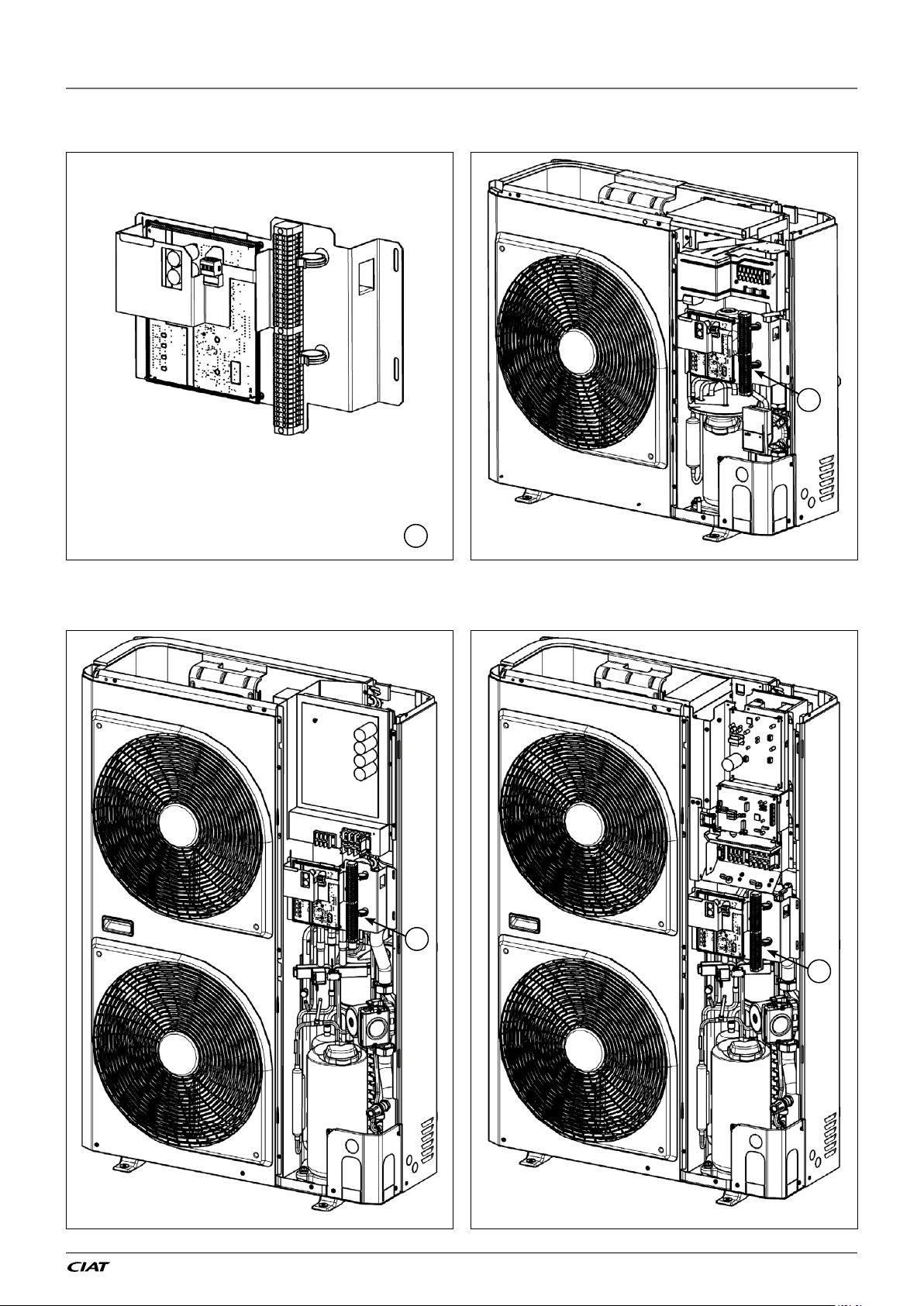
1.5.3 - Inside view
Electrical box 5 - 7 kW unit (1 Ph)
1
1
11 - 15 kW unit (1 Ph) 11 - 15 kW unit (3 Ph)
1
1
EN-17
EREBA He
1 - INTRODUCTION
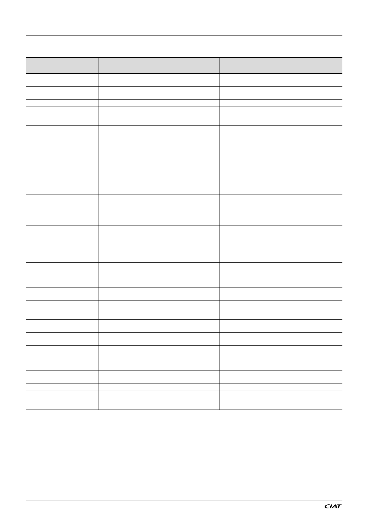
1.6 - Accessories
Accessories Reference Description Advantages Utilisation
Hydraulic tubes 7187601
Rubber cushion 7447060
Floor heating thermal cut off 7274278 Floor heating protection Reduces risk of floor heating dammage EREBA He
Backup heater 5kW 7148641 Electrical backup system
Backup heater 9kW 7148642 Electrical backup system
Backup heater for 9 kW for buffer tank
(100L & 200L)
Buffer tank 50L 7328746
Buffer tank 100L 7328744
Buffer tank 200L 7328747
Master / Slave sensor 7484985
Domestic hot water tank 300 L 7385910
Domestic hot water management
sensor and 3 way valve
"Pool heating management sensor
and 3 way valve"
Pool heating heat exchanger
(ITEX POOL +)
Remote human interface Standard Remotely installed user interface
Additional outdoor ambient
temperature sensor
Water filling kit 7013876 System enabling to fill the hydraulic circuit Hydraulic circuit easy filling EREBA He
DUO hydraulic module (for floor
heating < 11kW)
7221389 Electrical backup system Easy and fast installation inside the buffer tank EREBA He
7411357
71111 22
7268480
7484983 Additional outdoor ambient temperature sensor Better reading of outdoor air temperature EREBA He
3911008
Tubes are used to decoupling hydraulic circuits
and the units
Cushion installed under the unit to avoid
vibration trasmission
Buffer tank available to resolve installions
constraints
Buffer tank available to resolve installation
constraints
Buffer tank available to resolve installation
constraints
Unit equipped with supplementary water outlet
temperature sensor kit to be field-installed
allowing master/slave operation of two to four
units connected in parallel
Tank designed to satisfy sanitary hot water
productions
Sensor enabling to manage the water setpoint
inside the tank used for domestic hot water
production
Sensor enabling to manage the water setpoint
used for pool heating
Essential parts to ensure good working of pool
heating
This hydraulic module allows to manage two
differents heat emitters (Ex: floor heating and
radiators)
Reduces vibration transmission to hydraulic
installation
Reduces vibration transmission EREBA He
Easy and fast installation, stepped power,
hydraulic securities integrated (water relief
valve, automatic purge)
Easy and fast installation, stepped power,
hydraulic securities integrated (water relief
valve, automatic purge)
Reduce unit cycling increasing reliability, play
the roule of hydraulic separation to improve
the control of water flow rate and water
temperature in the system and finally, increase
thermal inertia during defrost and options mode
operation
Reduce unit cycling increasing reliability, play
the roule of hydraulic separation to improve the
control of water flow rate and water temperature
in the system and increase thermal inertia
during defrost and options mode operation
Reduce unit cycling increasing reliability, play
the roule of hydraulic separation to improve
the control of water flow rate and water
temperature in the system and finally, increase
thermal inertia during defrost and options mode
operation
Optimised operation of chillers connected in
parallel with operating time equalisation
Easy and fast installation, isolated tank to
reduce heat loss
Useful for domestic hot water production EREBA He
Useful for pool heating production EREBA He
Titanium exchangers plates, removable, easy
maintenance
Remote heat pump control with room
temperature sensor used to offset the water
control point.
Possibility to configure the unit on field.
Easy and fast installation, independant control
integrated
EREBA He
EREBA He
EREBA He
EREBA He
EREBA He
EREBA He
EREBA He
EREBA He
EREBA He
EREBA He
EREBA He
EREBA He
EN-18
2 - INSTALLATION OF UNIT
2.1 - General
To install an unit EREBA He the following
steps are requested
1. Place the unit
2. Make hydraulic connections to filling the
system with water or brine fluid
3. Make electrical connections
4. Check for water leaks and the water flow
rate control
5. Finally, make commissioning of the unit
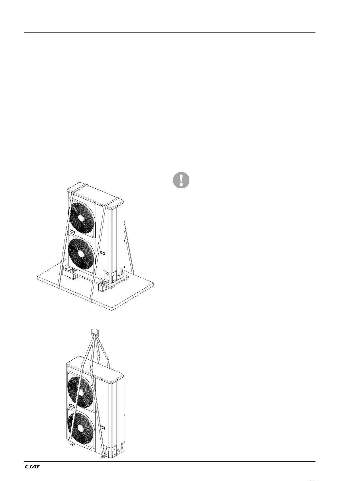
2.2 - Moving and placing the unit
2.2.1 - Moving
See §1.2.1 Installation safety considerations.
Figure 1: Transport configuration
2.2.2 - Placing the unit
In case of extra-high units the machine
environment must permit easy access for
maintenance operations.
Always refer to § 1.4. Dimensions and
clearances to conrm that there is
adequate space for all connections and
service operations. For the centre of
gravity coordinates, the position of the unit
mounting holes, and the weight distribution
points, refer to the certied dimensional
drawing supplied with the unit.
Typical applications of these units do not
require earthquake resistance. Earthquake
resistance has not been veried.
Only use slings at the designated
lifting points (refer to Figure 2 to
ofoad the unit).
Before siting the unit check that:
Figure 2: Offloading configuration
● the permitted loading at the site is
adequate or that appropriate strengthening
measures have been taken.
● if the unit has to operate as a heat pump
in temperatures below 0°C it must be
raised at least 300 mm from the ground.
This is necessary to avoid ice build-up
on the unit chassis and also to permit
correct unit operation in locations where
the snow level may reach this height.
● the unit is installed level on an even
surface (maximum tolerance is 5 mm in
both axes).
● there is adequate space above the unit
for air flow and to ensure access to the
components (see dimensional drawings).
● the number of support points is adequate
and that they are in the right places.
● the location is not subject to flooding.
● for outdoor installations, where heavy
snowfall is likely and long periods of
sub-zero temperatures are normal,
provision has to be made to prevent snow
accumulating by raising the unit above
the height of drifts normally experienced.
Baffles may be necessary to deflect
strong winds. They must not restrict air
flow into the unit.
EN-19
EREBA He
2 - INSTALLATION OF UNIT
● OAT sensor, located on the coil, should
not be exposed to the sun or other heat
sources.
Before lifting the unit, check that
all casing panels are securely xed
in place. Lift and set down the unit
with great care. Tilting and jarring
can damage the unit and impair unit
operation.
Never push or lever on any of the
enclosure panels of the unit. Only
the base of the unit frame is designed
to withstand such stresses. If a unit
includes a hydraulic module, the
hydraulic module and pump piping
must be installed in a way that
does not submit it to any strain.
The hydraulic module pipes must
be tted so that the pump does not
If EREBA He units are hoisted with rigging, it
support the weight of the pipes.
is advisable to protect coils against crushing
while a unit is being moved. Use struts or a
lifting beam to spread the slings above the
unit. Do not tilt a unit more than 15°.
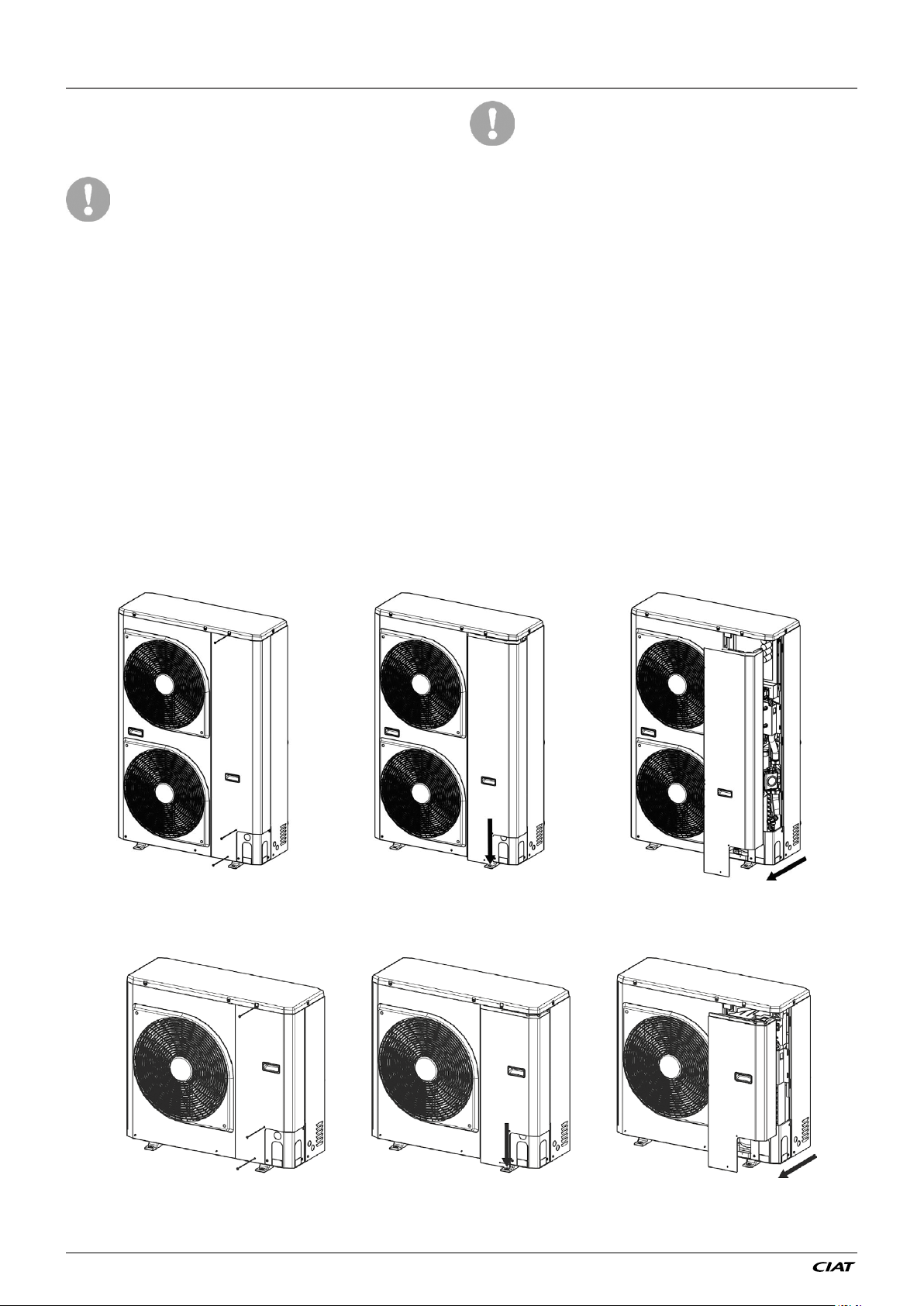
2.2.3 - Removing the unit panel
To access at the inside of the unit (refrigerant parts / electrical parts), the panel can be
removed. This operation must be carried out by a qualified technician.
Figure 3 : How to remove front panel for 11 & 15 kW units
Figure 4 : How to remove front panel for 5 & 7 kW units
EREBA He
EN-20
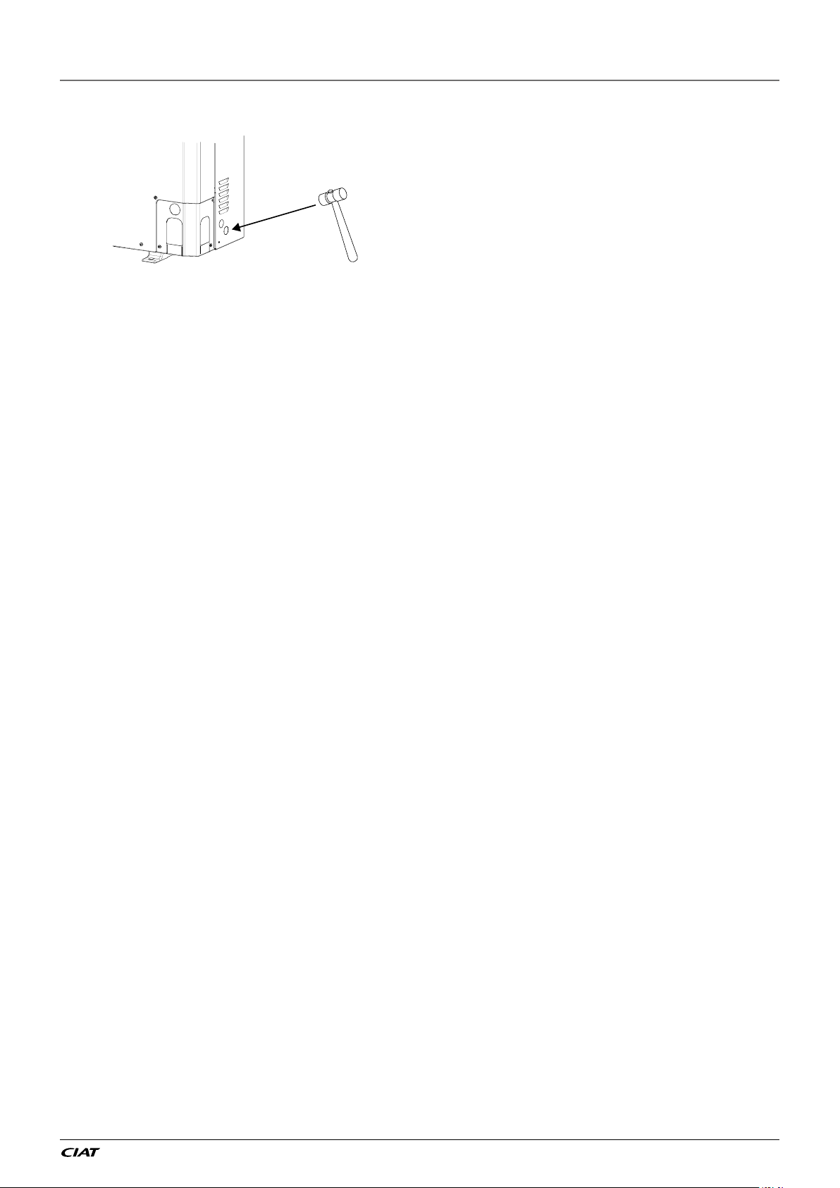
2 - INSTALLATION OF UNIT
Figure 5 : Opening cable knockouts
2.2.4 - Checks before system start-up
Before the start-up of the refrigeration
system, the complete installation, including
the refrigeration system must be verified
against the installation drawings, dimensional
drawings, system piping and instrumentation
diagrams, and wiring diagrams.
For these checks national regulations must
be followed. If the national regulation does
not specify any details, refer to standard ISO
5149 as follows:
External visual installation checks:
2.3 - Water connections
For size and position of the unit water inlet
and outlet connections refer to the certified
dimensional drawings supplied with the unit.
The water pipes must not transmit any radial
● Ensure that the machine is charged with
refrigerant. Verify on the unit nameplate
or axial force to the heat exchangers nor any
vibration.
that the ‘fluid being transported’ is R-410A
and is not nitrogen.
● Compare the complete installation with
the refrigeration system and power circuit
diag rams.
● Check that all components comply with
the design specifications.
● Check that all protection documents
and equipment provided by the
manufacturer (dimensional drawings,
P&ID, declarations etc.) to comply with
The water supply must be analysed and
appropriate filtering, treatment, control
devices, shut-off and bleed valves and
circuits built in, to prevent corrosion (example:
damage to the protection of the tube surface if
the fluid is polluted), fouling and deterioration
of the pump fittings.
Before any start-up verify that the heat
exchange fluid is compatible with the
materials and the water circuit coating.
the regulations are present.
● Verify that the environmental safety and
protection and devices and arrangements
provided by the manufacturer to comply
with the regulations are in place.
● Verify that all documents for pressure
In case additives or other fluids than those
recommended by the manufacturer are used,
ensure that the fluids are not considered as
a gas.
Recommendations on heat exchange uids:
containers, certificates, name plates,
files, instruction manuals provided by
the manufacturer to comply with the
regulations are present.
● Verify the free passage of access and
safety routes.
● Verify the instructions and directives
to prevent the deliberate removal of
refrigerant gases.
● Verify the installation of connections.
● Verify the supports and fixing elements
(materials, routing and connection).
● Verify the quality of welds and other
joints.
● Check the protection against mechanical
damage.
● Check the protection against heat.
● Check the protection of moving parts.
● Verify the accessibility for maintenance
or repair and to check the piping.
● Verify the status of the valves.
● Verify the quality of the thermal insulation
and of the vapour barriers.
● No NH4+ ammonium ions in the water, they
are very detrimental for copper. This is
one of the most important factors for the
operating life of copper piping. A content of
several tenths of mg/l will badly corrode the
copper over time.
EN-21
EREBA He

2 - INSTALLATION OF UNIT
● Cl- Chloride ions are detrimental for
copper with a risk of perforations by
corrosion by puncture. If possible keep
below 10 mg/l.
2-
● SO
sulphate ions can cause perforating
4
corrosion, if their content is above 30
mg/l.
● No fluoride ions (<0.1 mg/l).
● No Fe2+ and Fe3+ ions with non negligible
levels of dissolved oxygen must be
present. Dissolved iron < 5 mg/l with
dissolved oxygen < 5 mg/l.
● Dissolved silicon: silicon is an acid
element of water and can also lead to
corrosion risks. Content < 1mg/l.
● Water hardness: >0.5 mmol/l. Values
between 1 and 2.5 mmol/l can be
recommended. This will facilitate scale
deposit that can limit corrosion of copper.
Values that are too high can cause piping
blockage over time. A total alkalimetric
title (TAC) below 100 mg/l is desirable.
● Dissolved oxygen: Any sudden change
in water oxygenation conditions must be
avoided. It is as detrimental to deoxygenate
the water by mixing it with inert gas as
it is to over-oxygenate it by mixing it
with pure oxygen. The disturbance of
the oxygenation conditions encourages
destabilisation of copper hydroxides and
enlargement of particles.
● Electric conductivity: 0.001-0.06 S/m (10-
600 µS/cm).
● pH: Ideal case pH neutral at 20-25°C (7 <
pH < 8).
Charging, adding or draining uid
from the water circuit must be done
by qualied personnel, using air
vents and materials suitable for the
products. Water circuit charging
devices are eld-supplied.
The use of units in an open loop is
forbidden.
2.3.1 - Operating precautions and
recommendations
The water circuit should be designed to have
the least number of elbows and horizontal
pipe runs at different levels. Below the main
points to be checked for the connection:
● Comply with the water inlet and outlet
connections shown on the unit.
● Install manual or automatic air purge
valves at all high points in the circuit.
● Use a pressure reducer to maintain
pressure in the circuit(s) and install a
relief valve as well as an expansion tank.
Units with the hydraulic module include a
relief valve and an expansion tank.
● Install drain connections at all low points
to allow the whole circuit to be drained.
● Install stop valves, close to the entering
and leaving water connections.
● Use flexible connections to reduce
vibration transmission.
● Insulate all pipework, after testing for
leaks, both to reduce thermal leaks and
to prevent condensation.
● Use thermal tape to seal joints and to
seam the insulation.
● If the external unit water pipes are in an area
where the ambient temperature is likely
to fall below 0°C, they must be protected
against frost (frost protection solution or
trace heating).
● The use of different metals on hydraulic
piping could generate electrolytic pairs
and consequently corrosion. Verify then,
the need to install sacrificial anodes.
EREBA He
Charging and removing heat
exchange uids should be done with
devices that must be included on the
water circuit by the installer. Never
use the unit heat exchangers to add
heat exchange uid.
EN-22
2 - INSTALLATION OF UNIT
The plate heat exchanger can foul up quickly
at the initial unit start-up, as it complements
the lter function, and the unit operation will
be impaired (reduced water ow rate due to
increased pressure drop).
Units with hydraulic module are equipped
with a screen lter.
Do not introduce any signicant static or
pressures).
The products that may be added for thermal
insulation of the containers during the
water piping connection procedure must be
chemically neutral in relation to the materials
and coatings to which they are applied. This
is also the case for the products originally
supplied by the manufacturer.
dynamic pressure into the heat exchange
circuit (with regard to the design operating
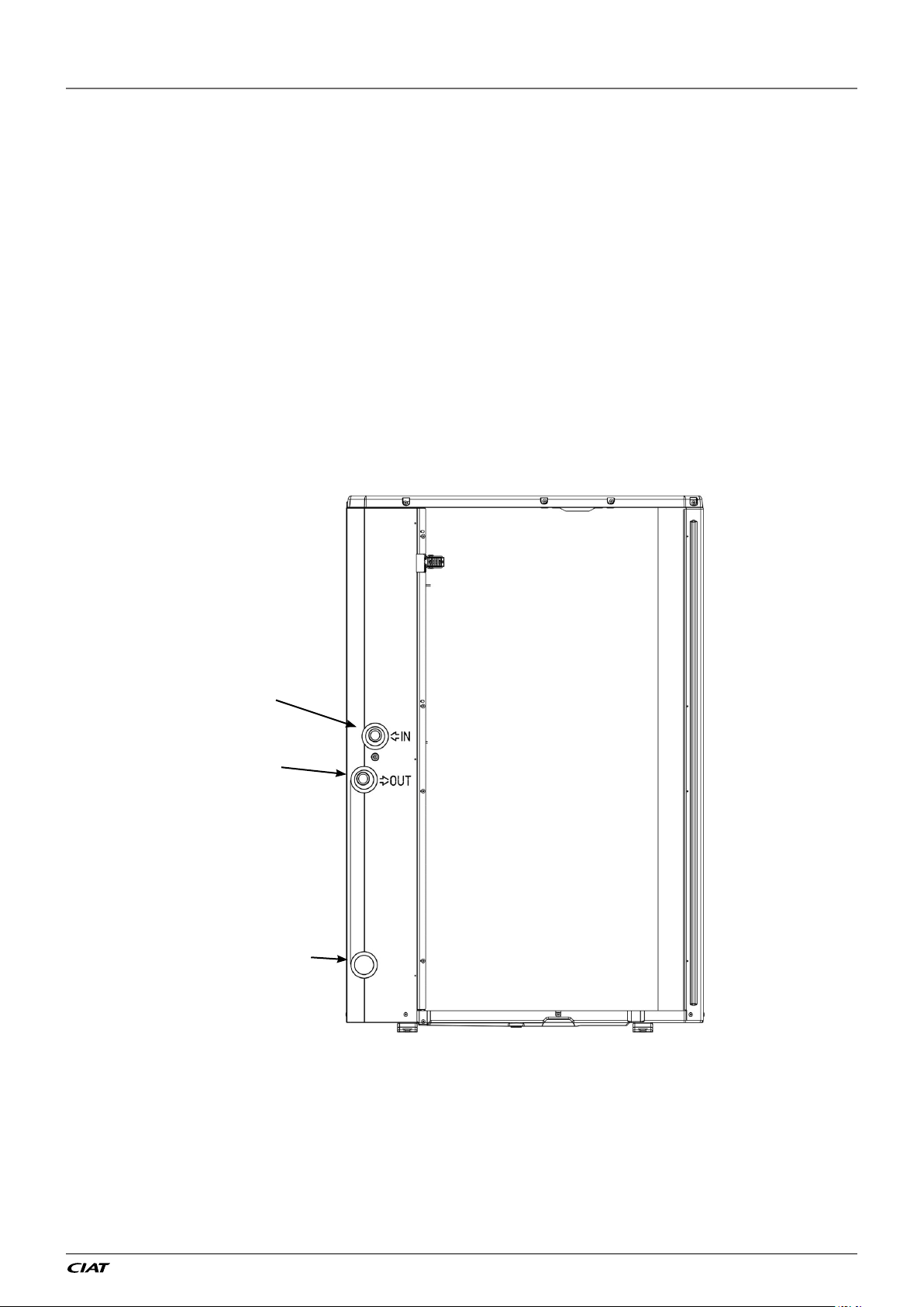
2.3.2 - General
For details on connection diameters, refer to §1.5.1 Physical data EREBA He.
Figure 6: Water connection on unit
Water inlet
Water outlet
Draining water pipe
EN-23
EREBA He
2 - INSTALLATION OF UNIT
3
2.3.3 - Minimum water loop volume
The minimum water loop volume, in litres, is
given by the following formula:
Volume (l) = CAP (kW) x N
Where CAP is the nominal cooling capacity
at nominal operating conditions.
Application N
Air conditioning 3,5
Heating or domestic hot water application 6
Industrial process cooling See note below
Note: For industrial process cooling applications, where high stability of
water temperature levels must be achieved, the values above must be
increased.We recommend consulting the factory for these particular
applications.
This volume is required to obtain temperature
stability and precision. To achieve this volume,
it may be necessary to add a storage tank to
the circuit. This tank should be equipped with
baffles to allow mixing of the fluid (water or
brine). Please refer to the examples below.
2.3.4 - Maximum water loop volume
Units with hydraulic module incorporate an
expansion tank that limits the water loop
volume. The table below gives the maximum
loop volume for pure water or ethylene glycol
with various concentrations.
If the total system volume is higher than the
values given above, the installer must add
another expansion tank, suitable for the
additional volume.
Water maximum volume (L)
EREBA He
Static pressure (bar) 1,5 3
Fresh water 200 50
Ethylen glycol 10% 150 38
Ethylen glycol 20% 110 28
Ethylen glycol 30% 90 23
Ethylen glycol 40% 76 19
Bad Good
GoodBad
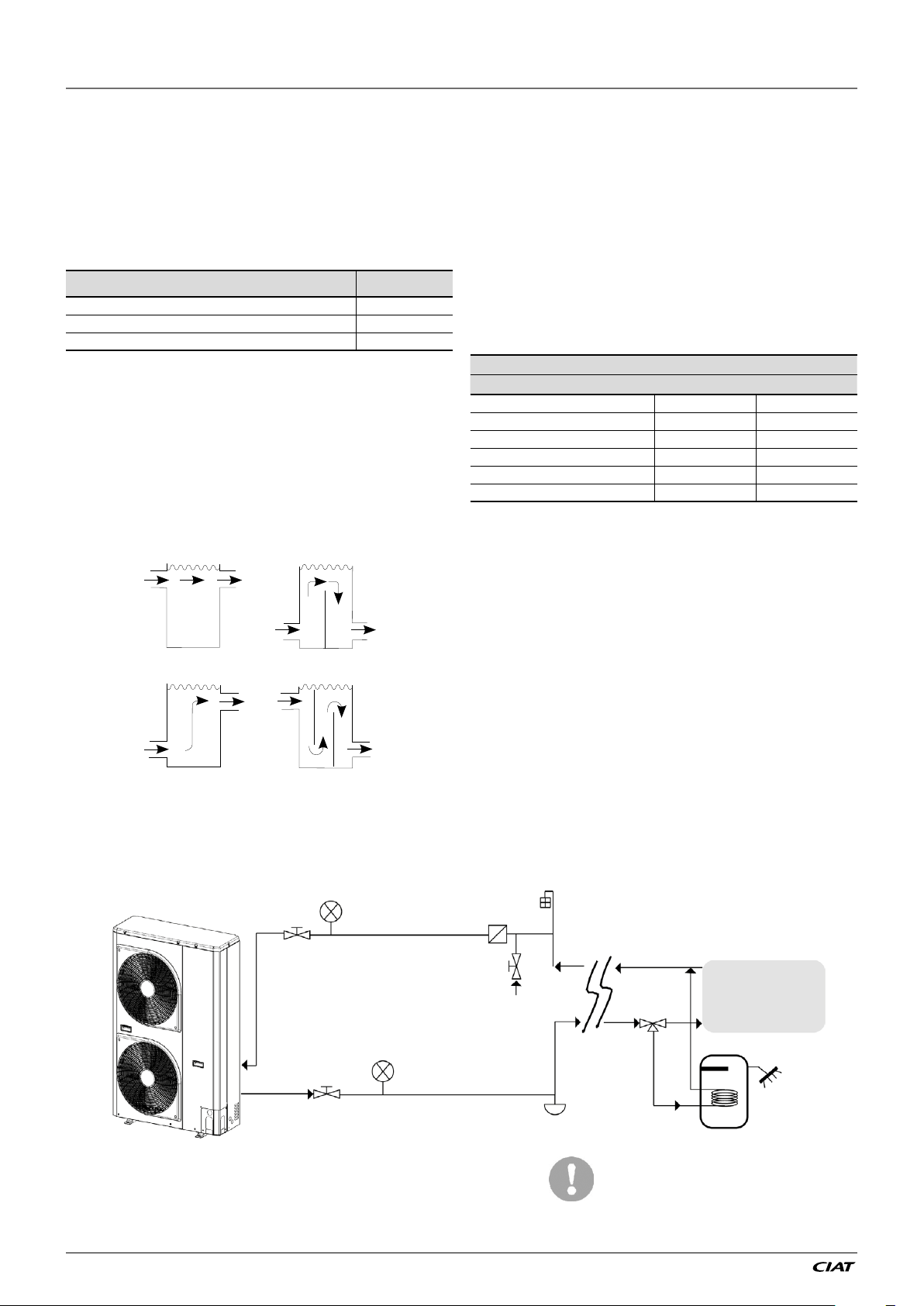
2.3.5 - Hydraulic circuit
Figure 7: Typical diagram of the hydraulic circuit with the hydraulic module
1
3
1
2
6
4
7
8
5
9
Legend:
1 Shut-off valves 2 Line filter for water 3 Pressure gauges
4 Filling valve 5 System drain valve 6 Air flushing valve
7 3-way valve 8 Sanitary water accumulation tank 9 Inside system
EREBA He
EN-24
The use of the hydraulic
module on open loop is
prohibited.
2 - INSTALLATION OF UNIT
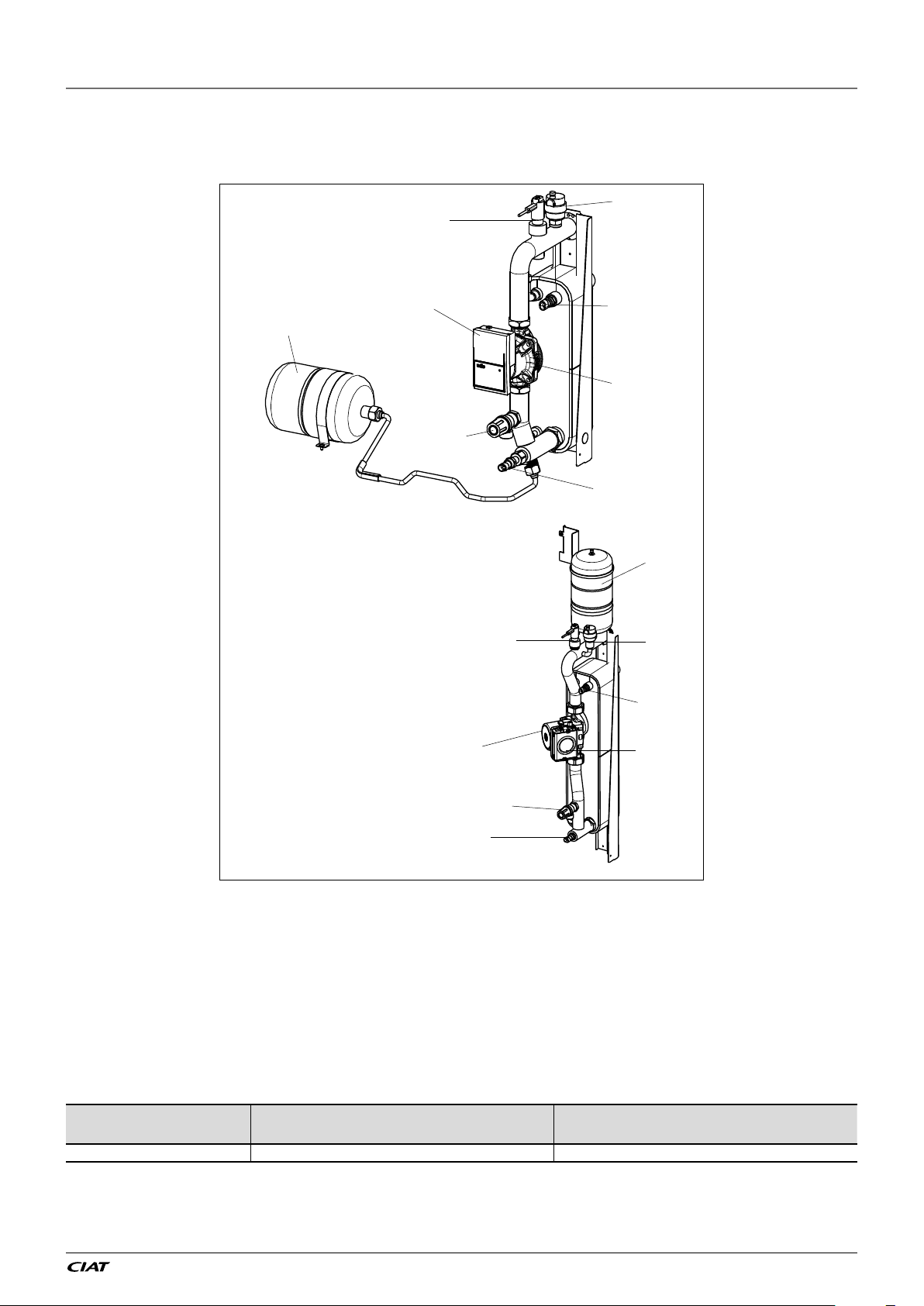
Figure 8: Hydraulic module equipped with variable speed single pump low
available pressure with expansion tank
Hydraulic module
a
b
5 & 7 kW units
g
e
c
f
b
d
f
h
g
a
d
e
11 & 15 kW units
c
h
Legend:
a Automatic purge valve
b Flow switch
c Safety valve outlet
d Leaving water temperature probe
e Circulation pump
f Plug to unblock the seizing pump
g Expansion vessel
h Entering water temperature probe
Minimum and maximum pressures necessary in the hydraulic circuit for correct operation of
the units.
Hydraulic circuit
Variable speed hydraulic module 40 kPa (0.4 bar) 300 kPa(3 bar).
Minimum pressure at the suction of the pump
to avoid the cavitation phenomena.
Maximum pressure at the suction of the pump
before the opening of the water relief valve
(1)
EN-25
EREBA He
2 - INSTALLATION OF UNIT
2.4 - Electrical connections
Please refer to the certified wiring drawings,
supplied with the unit.
2.4.1 - Power supply
The power supply must conform to the
specification on heat pump nameplate. The
supply voltage must be within the range
specified in the electrical data table. For
connections refer to the wiring diagrams and
the certified dimensional drawings.
After the unit has been commissioned,
the power supply must only be
disconnected for quick maintenance
operations (one day maximum). For
longer maintenance operations or
when the unit is taken out of service
and stored (e.g. during the winter or
if the unit does not need to generate
cooling) the power supply must be
maintained to ensure supply to the
electric heaters (compressor coil
heater, unit frost protection).
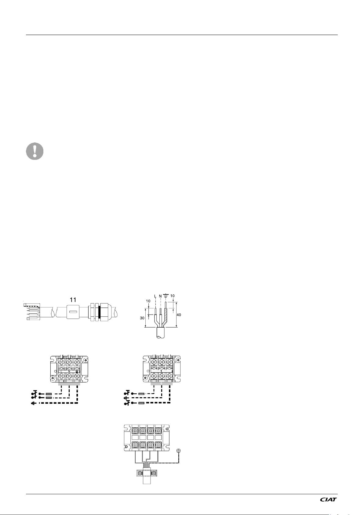
Figure 9: Power connection with Main
Switch
3Ph 1Ph
2.4.2 - Recommended wire sections
Wire sizing is the responsibility of the installer,
and depends on the characteristics and
regulations applicable to each installation
site. The following is only to be used as a
guideline, and does not make Manufacturer
in any way liable. After wire sizing has been
completed, using the certified dimensional
drawing, the installer must ensure easy
connection and define any modifications
necessary on site.
The connections provided as standard for
the field-supplied power entry cables are
designed for the number and type of wires,
listed in the table below.
The calculations of favourable and
unfavourable cases are performed by using
the maximum current possible of each unit
fitted with a hydraulic kit (see the tables of
electrical data for the unit and the hydraulic
module).
The calculation is based on PVC or XLPE
insulated cables with copper core. A
maximum ambient temperature of 46°C has
been taken into consideration. The given
wire length limits the voltage drop to < 5%
(length L in metres - see table below).
5-7 1Ph+N
L N
11-15 1Ph+N
L
L N
11-15 3Ph+N
L1 L2 L3
N
IMPORTANT:
Before connection of the main power cables
(L1 - L2 - L3 - N - PE or L1 - N - PE) on the
terminal block, it is imperative to check
the correct order of the 3 phases before
proceeding to the connection and the good
connection of the neutral wire (if the neutral
N
conductor is not connected correctly, the
unit can be damaged permanently).
EREBA He
EN-26
2 - INSTALLATION OF UNIT
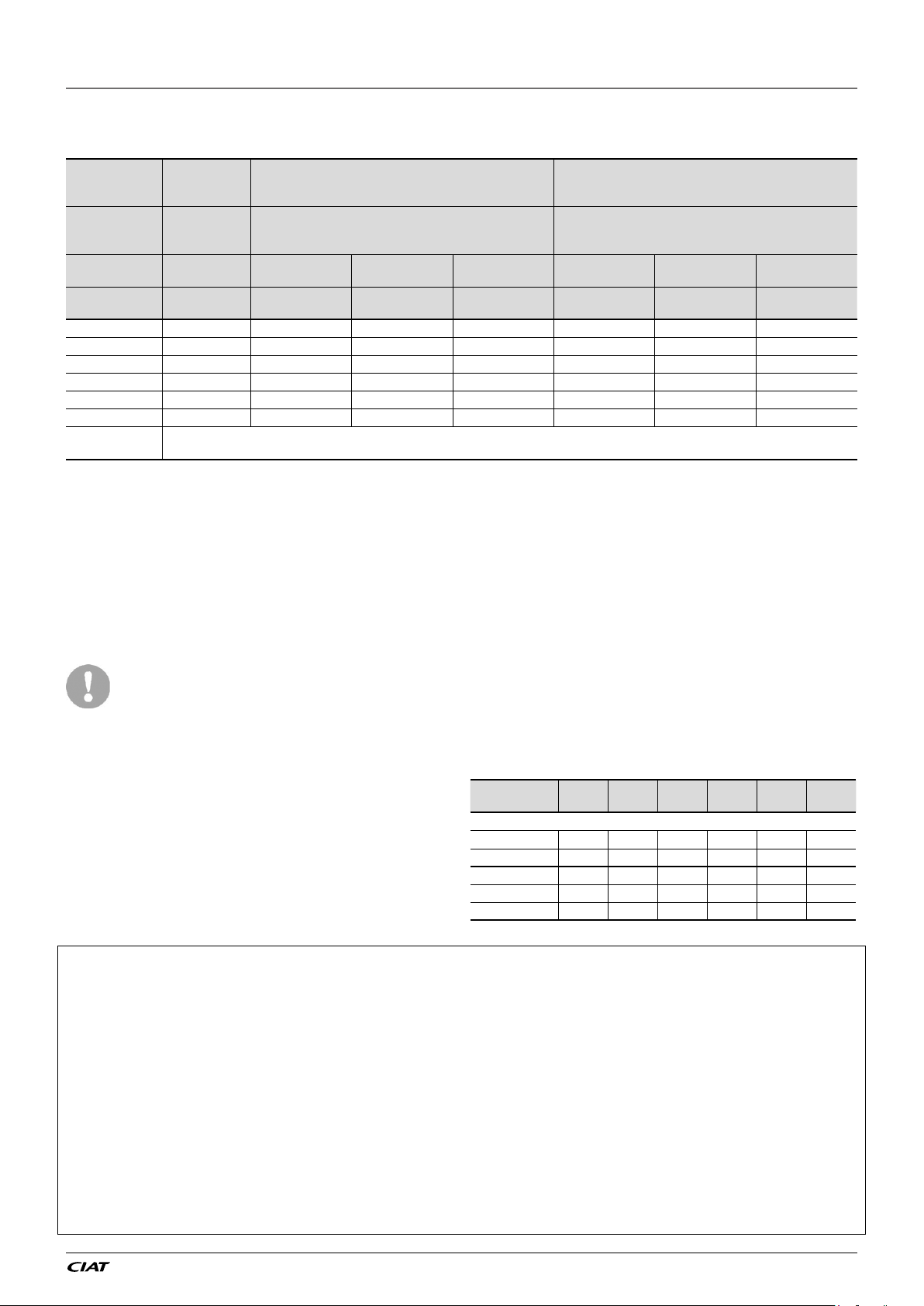
Table 1: Minimum and maximum wire section (per phase) for connection to
EREBA He units
Max.
connectable
EREBA He Section Section
(per phase)
5 (1Ph) 3G4² 3G2,5² 100 H07RNF 3G2,5² 80 H07RNF
7 (1Ph) 3G4² 3G2,5² 100 H07RNF 3G2,5² 80 H07RNF
11 (1Ph) 3G4² 3G4² 100 H07RNF 3G4² 80 H07RNF
15 (1Ph) 3G4² 3G4² 100 H07RNF 3G4² 80 H07RNF
11 (3Ph) 5G4² 5G2,5² 100 H07RNF 5G2,5² 80 H07RNF
15 (3Ph) 5G4² 5G2,5² 100 H07RNF 5G2,5² 80 H07RNF
Accessory
Remote WUI
Notes:
(1) Connection capacities actually available for each machine, defined according to the connection terminal size, the control box access opening size and the available
space inside the control box.
(2) Selection simultation result considering the hypothesis indicated.
(3) If the maximum calculated section is for an XLPE cable type, this means that a selection based on a PVC cable type can exceed the connection capacity actually
available. Special attention must be given to the selection.
Use cables H07RN-F 4x0.75 mm² up to 50m to connect the user interface WUI (not supplied with accessory)
CAUTION: Use the grey ferrite which is supplied in accessory to clamp around the WUI cable. Please clamp it directly after the customer's terminal block
section
mm²
(1)
- Suspended aerial lines (standardised routing No. 17)
- XLPE insulated cable
(per phase)
Calculation favourable case: Calculation unfavourable case:
- Conductors in conduits or multi-conductor cables
in closed conduit (standardised routing No. 41)
- PVC insulated cable, if possible
mm²
Max. length for
(2)
voltage drop <5%
Cable type Section
m -
mm²
(per phase)
Max. length for
(2)
voltage drop <5%
m -
Cable type
(3)
Power cable entry
The power cables must be entered through
the cable gland from the rear of the unit.
Use a black ferrite which is supplied
in accessory to clamp around the
supply cable. Please clamp it directly
after the customer’s terminal block.
Please clamp the second one close
to the cable gland.
The power cable should not be in
contact with hot parts of the system.
Electrical data and operating conditions notes:
• EREBA He units have a single power connection point located immediately
upstream of the field power connections.
• The control box includes the following standard features:
- Variable frequency drive for compressor, fans and pump (option)
- The control devices.
• Field connections:
All connections to the system and the electrical installations must be in full accordance
with all applicable local codes.
• The ERE BA He units are designed and built in compliance with EN 60335-1 and 2
NOTES:
• The operating environment for the EREBA He units is specified below:
1. Physical environment
EN 60364:
- outdoor installation: protection level IP44
- operating temperature range: -20°C to +46°C
- storage temperature range: -20°C to +48°C
- altitude: ≤ 2000 m (see note for table 1.5.4 - Electrical data, hydraulic module)
- presence of hard solids, class AE3 (no significant dust present)
- presence of corrosive and polluting substances, class AF1 (negligible)
(2)
. The classification of environment is specified in standard
(2)
(1)
.
2.4.3 - Recommended customer
electrical protection
Electrical protection is the responsibility of the
installer, and depends on the characteristics
and regulations applicable to each installation
site. The following is only to be used as a
guideline, and does not make manufacturer
in any way liable.
5
EREBA He
Circuit breaker:
Type C C C C C C
Current A 10 16 25 25 16 16
Fuses:
Type gG gG gG gG gG gG
Current A 16 20 32 32 20 20
2. Power supply frequency variation: ± 2 %.
3. The neutral (N) conductor must be always connected to the unit
4. Overcurrent protection of the power supply conductors is not provided with the
unit.
5. The units are designed for simplified connection on TT networks (IEC 60364).
Caution: If particular aspects of an actual installation do not conform to the
conditions described above, or if there are other conditions which should be
considered, always contact your local representative.
(1) The absence of main power disconnect switch is an exception that must be
taken into account at field installation level.
(2) The required protection level for this class is IP43BW (according to reference
document IEC 60529). All EREBA He units fulfil this protection condition:
- Closed electrical box is IP44
- When accessing to interface, the level is IPxxB
(1Ph)
7
(1Ph)
11
(1Ph)
15
(1Ph)
11
(3Ph)
15
(3Ph)
EN-27
EREBA He
2 - INSTALLATION OF UNIT
2.5 - Water flow rate control
2.5.1 - Water leakage
Check that the water-side connections are
clean and show no sign of leakage.
2.5.2 - Minimum water flow rate
If the installation flow rate is below the
minimum flow rate, there is a risk of excessive
fouling.
2.5.3 - Maximum water flow rate
This is limited by the permitted water heat
exchanger pressure drop.
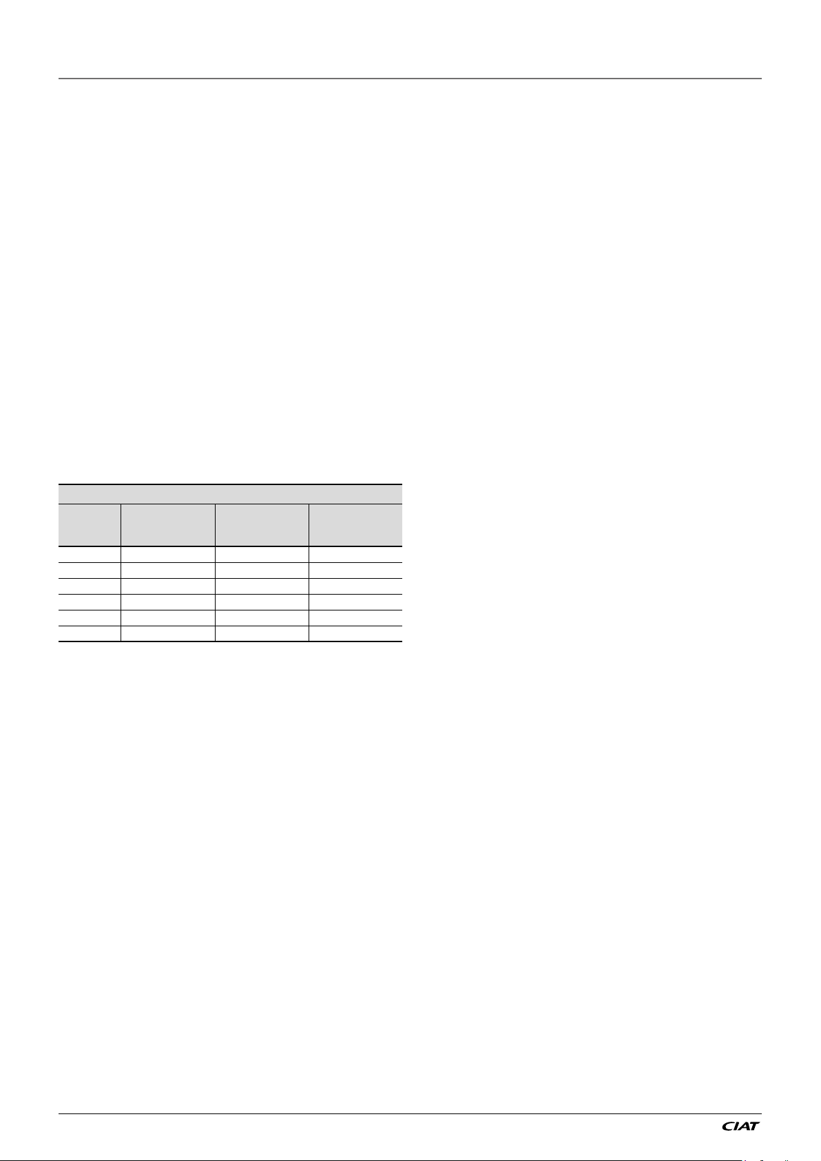
2.5.4 - Water heat exchanger flow rate
Data applicable for:
- Fresh water 20°C
- In case of use of the glycol, the
maximum water flow is reduced.
EREBA He units
Minimum water
flow rate
m3/h
5 (1Ph) 0,18 0,9 4,3
7 (1Ph) 0,42 1,2 4,3
11 (1Ph) 0,6 1,9 7,0
15 (1Ph) 0,6 2,6 7,0
11 (3Ph) 0,6 1,9 7,0
15 (3Ph) 0,6 2,6 7,0
(1) Eurovent heating conditions
Nominal water
flow rate
m3/h
Maximum water
(1)
flow rate
m3/h
2.5.5 - Nominal system water flow
control
The water circulation pumps of the EREBA He
units have been sized to allow the hydraulic
modules to cover all possible configurations
based on the specific installation conditions,
i.e. for various temperature differences
between the entering and the leaving water
(∆T) at full load, which can vary between 3
and 10 K.
This required difference between the entering
and leaving water temperature determines
the nominal system flow rate. Use this
specification for the unit selection to find the
system operating conditions.
In particular, collect the data to be used for
the control of the system flow rate:
● Units with variable speed pump-control
on adjustable constant speed: nominal
flow rate,
● Units with variable speed pump -
control on temperature difference: heat
exchanger ΔT (variable flow).
If the information is not available at the
system start-up, contact the technical service
department responsible for the installation to
get it. These characteristics can be obtained
from the technical literature using the unit
performance tables for a ∆T of 5 K at the
water heat exchanger.
EREBA He
EN-28
2 - INSTALLATION OF UNIT
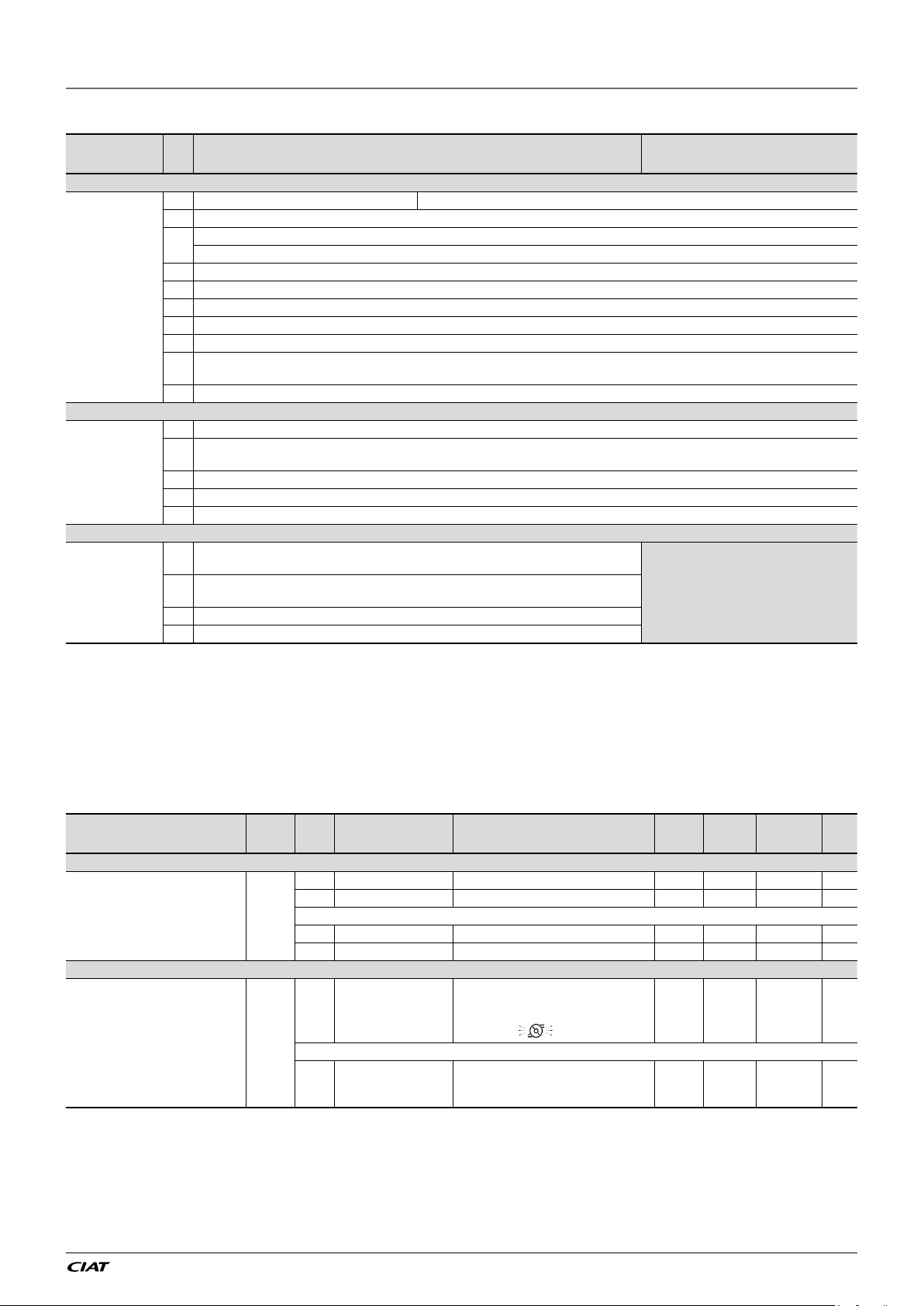
Table 2: Steps to clean, purge, and define a flow rate for hydraulic circuit
Cleaning
procedure
Purge
procedure
Water flow
control
procedure
N°
1 Open the manual control valve fully. No manual control valve required with Variable Speed Hydraulic module
2 Set the system pump
Read the BPHE pressure drop...
3
… by taking the difference of the readings of the pressure gauge connected to the unit inlet and outlet.
4 Let the pump run for two consecutive hours to flush the hydraulic circuit of the system (presence of solid contaminants).
5 Take another reading.
6 Compare this value to the initial value.
7 If the pressure drop…
… has decreased, this indicates that the screen filter must be removed and cleaned, as the hydraulic circuit contains solid particles.
In this case stop the pump
8
section of the unit.
9 Repeat, if necessary, to ensure that the filter is not contaminated.
1 After filling with water, wait about 24h before activating the purge procedure.
Activate the purge mode
2
switch value
3 The air purge is field-supplied.
If the purge is automatic, air will vent from circuit automatically.
If the purge is manual, open the valve to vent air from the circuit
When the circuit is cleaned and purged, activate the pump in quick test mode
1
pressures at the pressure gauges (entering water pressure - leaving water pressure), …
Compare this value to the graph of available external static pressure using the appropriate speed
3
curve (Graphic 1).
4 If the flow rate corresponding is higher, decrease pump speed
5 Proceed by successively adjusting the pump speed until the expected water flow rate is achieved.
(2)
With Variable Speed Hydraulic module
Adjustable constant speed
(1)
.
(1)
and close the shut-off valves at the water inlet and outlet and remove the screen filter after emptying the hydraulic
(1)
.
: water pump is requested to run continuously at maximum speed to purge the hydraulic circuit regardless the flow
(1)
, and vice versa.
(1)
, and read the
With Variable Speed Hydraulic
No need to adjust the flow rate because of
ΔT control.
But it is necessary to adjust the Minimum
pump speed [P567]to ensure closure of flow
switch
(1)
.
module ΔT
(1) For configuration details, refer to table 3.
(2) CAUTION: In purge mode, the value of the flow switch is ignored, so check that there is water in the circuit, to avoid damage to the pump.
Table 3:
Actions in WUI parameter menu or Service tools to activate the cleaning
purge and control of flow rate for hydraulic circuit
Steps Table Par. Designation Description Range Default Ex. Unit
321 Quick Test enable Access to Quick test mode 0 to 1 0 1 -
331 Water Pump Speed Activate the pump 0 to 100 0 100 %
Wait around 2h that the hydraulic circuit is cleaned
331 Water Pump Speed Stop the pump 0 to 100 0 0 %
321 Quick Test enable Exit the Quick test mode 0 to 1 0 0 -
8 = Purge (water pump is constantly
REQ
44 System Mode Request
44 System Mode Request
running to purge the hydraulic circuit)
0 to 6 and 9 = not used for this
configuration
Wait that the circuit purges
To exit purge mode, change the value of
[P044] with the wanted mode (0 or 1 or
2 or 4)
0 to 9 - 8 -
0 to 9 - 0 / 1 /2 /4 -
Cleaning procedure
Purge procedure
QCK_
TEST
MOD_
EN-29
EREBA He
 Loading...