

CIAT DynaCIAT LG, DynaCIAT LGN User Manual

ECG–UG–16-014
REVISION
DATE
PAGE
DynaCIAT LG/LGN
– Modbus
Communication
Original
03/04/2017
1 OF 21
This document is the property of CIAT Corporation and is delivered on the express condition that it is not to be
disclosed, reproduced in whole or in part, or used for manufacture by anyone other than CIAT Corporation without
its written consent, and that no right is granted to disclose or so use any information contained in said document.
Connect Touch Control for DynaCIAT LG/LGN
chillers
MODBUS COMMUNICATION
User’s guide
ECG–UG–16-014
REVISION
DATE
PAGE
DynaCIAT LG/LGN
– Modbus
Communication
Original
03/04/2017
2 OF 21
This document is the property of CIAT Corporation and is delivered on the express condition that it is not to be disclosed, reproduced in whole or in part, or used for manufacture
by anyone other than CIAT Corporation without its written consent, and that no right is granted to disclose or so use any information contained in said document.
REVISIONS HISTORY
REV
DATE yyyy mm dd
DESCRIPTION
DONE BY
Original
2017-04-03
Original
JA

ECG–UG–16-014
REVISION
DATE
PAGE
DynaCIAT LG/LGN –
Modbus
Communication
Original
03/04/2017
3 OF 21
This document is the property of CIAT Corporation and is delivered on the express condition that it is not to be
disclosed, reproduced in whole or in part, or used for manufacture by anyone other than CIAT Corporation
without its written consent, and that no right is granted to disclose or so use any information contained in said
document.
TABLE OF CONTENT
REVISIONS HISTORY ............................................................................................................... 2
TABLE OF CONTENT ............................................................................................................... 3
1 INTRODUCTION ............................................................................................................... 4
1.1 Purpose .......................................................................................................................... 4
1.2 Definitions, Abbreviations and acronyms ......................................................................... 4
2 CONNECTION CHANNELS .................................................................................................... 5
2.1 RS485 socket details........................................................................................................ 5
2.2 RJ45 socket details .......................................................................................................... 6
3 MODBUS FUNCTIONS ....................................................................................................... 7
4 MAPPING INTERFACE ........................................................................................................ 8

ECG–UG–16-014
REVISION
DATE
PAGE
DynaCIAT LG/LGN –
Modbus
Communication
Original
03/04/2017
4 OF 21
This document is the property of CIAT Corporation and is delivered on the express condition that it is not to be
disclosed, reproduced in whole or in part, or used for manufacture by anyone other than CIAT Corporation
without its written consent, and that no right is granted to disclose or so use any information contained in said
document.
1 INTRODUCTION
1.1 Purpose
This guide is intended to be used by Building Management System (BMS) engineer inside or outside the CIAT
Corporation.
It describes in details the Modbus communication with DynaCIAT LG/LGN units.
All information already provided in the product IOM are not available in this document.
1.2 Definitions, Abbreviations and acronyms
Acronym
/Abbreviation
Definition
DI
Discrete Input
EXV
Expansion Valve
FC
Free Cooling
HR
Holding Register
IEEE
Institute of Electrical and Electronics Engineers
IP
Internet Protocol
IR
Input Register
Net
Network
OAT
Outside Air Temperature
RTU
Remote Terminal United Technologies Corporation
SCT
Saturated Condensing Temperature
SST
Saturated Suction Temperature
TCP
Transmission Control Protocol
xxLS
..Low Speed
xxHS
..High Speed
ECG–UG–16-014
REVISION
DATE
PAGE
DynaCIAT LG/LGN –
Modbus
Communication
Original
03/04/2017
5 OF 21
This document is the property of CIAT Corporation and is delivered on the express condition that it is not to be
disclosed, reproduced in whole or in part, or used for manufacture by anyone other than CIAT Corporation
without its written consent, and that no right is granted to disclose or so use any information contained in said
document.
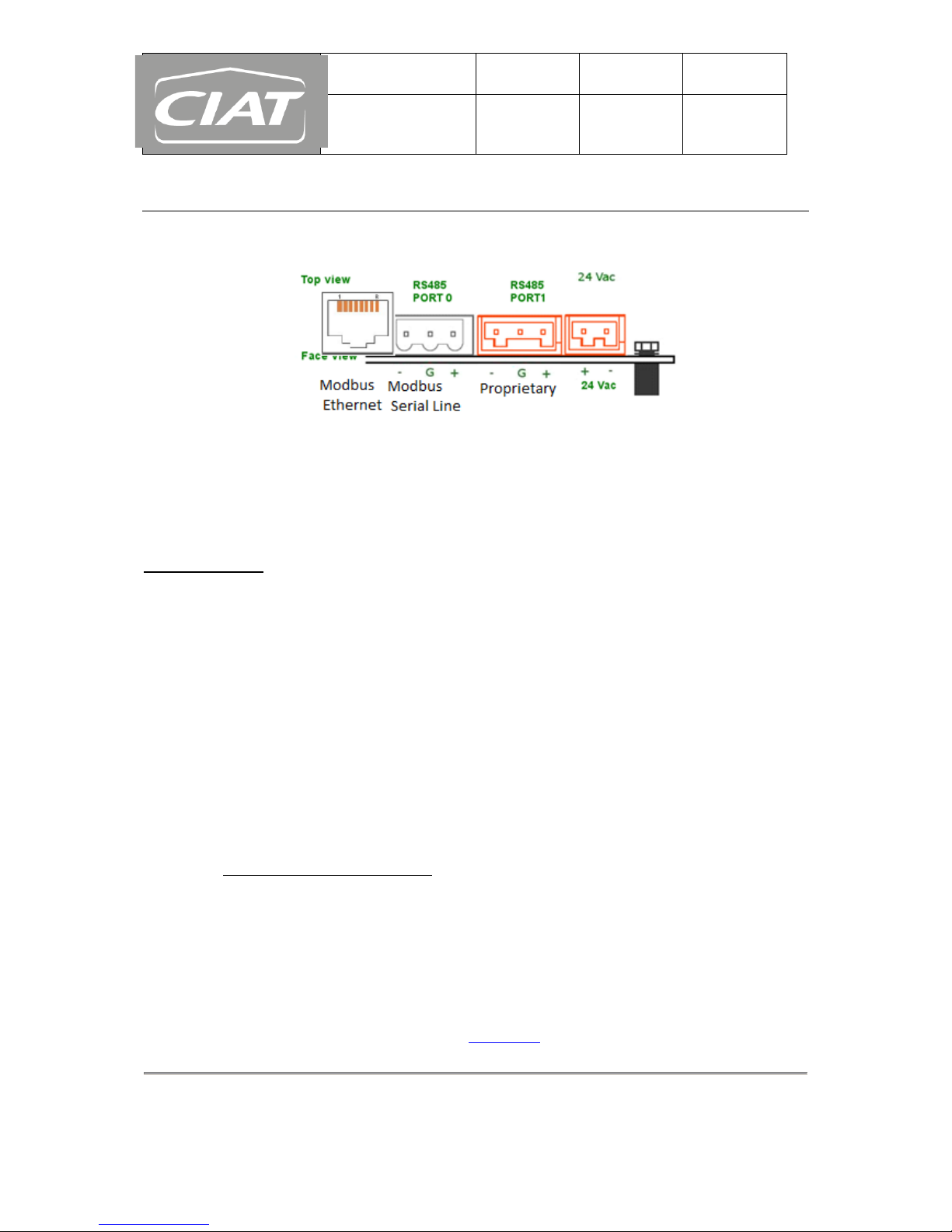
2 CONNECTION CHANNELS
Here below sockets available for communication purposes with external devices.
sockets identification available for communication
NB: PORT 0 should be used only if it is not already used to connect a gateway integrated in the unit.
2.1 RS485 socket details
Bus “port0” is intended to Modbus serial line with RS485 (i.e. no control flow)
Transmission mode:
Used for Local area network communication type by external devices.
With twisted shielded pair
distance up to 1000m without amplifier
Normally configurable at 9600, 19200 or 38400 baud in half duplex.
Parity bit may be active or deactivated. If parity is disabled, additional stop bits are automatically
set for frame timing considerations. Otherwise, parity may be odd or even according to the
settings chosen.
Exclusively RTU mode operates with configurable combination (No ASCII mode permission)
1 start, 8 data, even parity, 1 stop bit
1 start, 8 data, odd parity, 1 stop bit
1 start, 8 data, even parity forced, 1 stop bit
1 start, 8 data, odd parity forced, 1 stop bit
1 start, 8 data, 2 stop bit
1 start, 8 data, no parity , 1 stop bit (EXCLUDED)
RTU protocol is compatible with both Little/ Big Endian for data field (i.e. either most significant
byte is sent first or Least significant byte is sent first)
Unit identifier must be declared from 1 to 247 as slave product number setup (i.e. station
number)
Cyclic Redundancy Check is made by the RTU protocol layer as defined in Appendix A of “Modbus
over serial line” specification available at modbus.org

ECG–UG–16-014
REVISION
DATE
PAGE
DynaCIAT LG/LGN –
Modbus
Communication
Original
03/04/2017
6 OF 21
This document is the property of CIAT Corporation and is delivered on the express condition that it is not to be
disclosed, reproduced in whole or in part, or used for manufacture by anyone other than CIAT Corporation
without its written consent, and that no right is granted to disclose or so use any information contained in said
document.
Due to floating no native floating point representation for the Modbus communication protocol,
IEEE754 representation has been integrated. As the opposite, float handled as integer is also
available (i.e. float X 10) depending on setup.
Bus “port1” is proprietary and therefore reserved for internal purpose.
2.2 RJ45 socket details
Modbus Ethernet is intended to Modbus IP.
Used for wide area network communication type by external devices (building management system tool or
maintenance tool and so on…)
Cross pair wired cable shall be used for nominal configuration.
distance up to 100m without amplifier
Speed communication at 10 Mega baud not configurable
IPv4 address configurable for class address with DHCP NOT active for
Class A (0.xxx.xxx.xxx to 127.xxx.xxx.xxx)
Class B (128.0.xxx.xxx to 191. 255.xxx.xxx)
Class C (192.0.0.xxx to 223.255.255.xxx)
(IP address declared on the control unit needed to set up connection with external device)
All requests are sent via Transfer Control Protocol on registered port 502 by default but other port
number may be set as calibrate value.
TCP/IP Modbus protocol is compatible with both Little/ Big Endian for data field (i.e. either most
significant byte is sent first or Least significant byte is sent first)
Unit identifier must be declared from 1 to 247 as slave product number setup (i.e. station
number)

ECG–UG–16-014
REVISION
DATE
PAGE
DynaCIAT LG/LGN –
Modbus
Communication
Original
03/04/2017
7 OF 21
This document is the property of CIAT Corporation and is delivered on the express condition that it is not to be
disclosed, reproduced in whole or in part, or used for manufacture by anyone other than CIAT Corporation
without its written consent, and that no right is granted to disclose or so use any information contained in said
document.
3 MODBUS FUNCTIONS
The following standard functions are supported:
Code
Modbus function
Address register range
Application
01 with quantity 1
READ COIL STATUS
0 to 9999 (decimal)
None
01 with quantity N
READ MULTIPLE COIL STATUS
(from 1 to 2000max.
contiguous)
None
15 with quantity 1
WRITE COIL
None
15 with quantity N
WRITE MULTIPLE COILS (from 1
to 2000max. contiguous)
None
02 with quantity 1
READ DISCRETE INPUT
0 to 9999 (decimal)
Alarms
02 with quantity N
READ MULTIPLE DISCRETE
INPUTS (from 1 to 2000max.
contiguous)
04 with quantity 2
READ INPUT REGISTER
0 to 9999 (decimal)
Useful user parameters
04 with quantity NX2
READ MULTIPLE INPUT
REGISTERS (from 1 to 123 max.
contiguous)
Useful user parameters
03 with quantity 2
READ HOLDING REGISTER
0 to 9999 (decimal)
Configuration or service dataset
03 with quantity NX2
READ MULTIPLE HOLDING
REGISTERS (from 1 to 123 max.
contiguous)
Configuration or service dataset
16 with quantity 2
WRITE HOLDING REGISTER
Configuration or service dataset
16 with quantity NX2
WRITE MULTIPLE HOLDING
REGISTERS (from 1 to 123 max.
contiguous)
Configuration or service dataset
 Loading...