

Page 1

Microchip and LCD display
electronic regulation and
signaling electronic module
for liquid coolers
and heat pumps
NA 09.13 H
09 - 2011
Installation
Operation
Commissioning
Maintenance
1
Page 2

Page 3
CONTENTS
PAGE
1 IMPORTANT RECOMMENDATIONS
3
2 GENERAL
3
3 Composition
4
3.1 Main control board for machines with one refrigerating circuit
4
3.2 Additional board 1
5
3.3 Additional board 2
6
3.4 Control and display console
7
3.5 Connection via RS485 serial port for BMS or control console and Multiconnect with 500 kW module
8
3.6 Relay boards
9
4 DESCRIPTION
9
4.1 Main board
9
4.2 Expansion (additional) boards 1 and 2
9
4.3 Man-Machine Communication
10
5 ACCESS LEVELS
10
5.1 Selecting an authorised access level
10
5.2 Accessing the various access levels
10
5.3 Configuring access levels on the controller
12
5.4 Management of the numeric codes for accessing levels 2 and 3
12
5.5 Classification of the menus and their functions
12
6 LIST OF PARAMETERS PER ACCESS LEVEL
12
7 MANAGEMENT OF AERO-CONNECT PARAMETERS
20
8 CONTENTS OF THE MENUS
21
8.1 MAIN menu
21
8.2 SETPOINTS menu
21
8.3 MACHINE STATUS menu
22
8.4 MEASURED VALUES menu
26
8.5 MACHINE PARAMETERS menu
26
8.6 ADJUSTMENT PARAMETERS menu
31
8.7 OPERATION PARAMETERS menu
39
8.8 FAULT MEMORY menu
50
8.9 TEST MODE menu
51
9 MANAGEMENT OF THE ON/OFF INPUTS
52
9.1 Automatic machine operation control
52
9.2 Load shedding control
52
9.3 Water flow switch
52
9.4 Fan fault (circuits 1 and 2)
53
9.5 Expansion valve fault
53
9.6 Phase controller fault
54
9.7 Pump fault
54
9.8 Compressor protection
55
9.9 Manual HP pressure switch fault on circuit 1 or 2
55
9.10 Setpoint selection via on/off input
56
9.11 Variable setpoint via 4-20 mA input
56
9.12 Operating mode selection
57
10 MANAGEMENT OF THE ANALOGUE INPUTS
57
10.1 Temperature sensor
57
10.2 Pressure sensor
60
11 MANAGEMENT OF THE WATER PUMPS
61
11.1 Pump 1
61
11.2 Pump 2
61
11.3 Pump management if P2 = 3 (reversible air-to-water) + heating mode + P111 = boiler
61
11.4 Unseizing and switching the pumps
61
12 WINTER PROTECTION
61
12.1 Frost protection of pumps and heat exchangers while unit is off:
61
12.2 Water loop winter protection
62
1
Page 4

CONTENTS
PAGE
13 MANAGEMENT OF THE FUNCTIONS
62
13.1 Management of the compressor protections
62
13.2 Management of the time counters
63
13.3 Management of compressor start-up
63
13.4 Management of the reversing valves
64
13.5 Management of configurable output P111:
64
14 SELF-ADJUSTING FUNCTIONS
64
14.1 Self-adjusting function: water frost limit
64
14.2 Self-adjusting function: refrigerant frost limit
64
14.3 Self-adjusting function: HP pressure limit
65
14.4 Self-adjusting function: discharge protection, circuit 1 or 2
65
14.5 Self-adjusting function: minimum HP, circuit 1 or 2
65
14.6 Self-adjusting function for high water return temperatures
65
15 FAULT FUNCTIONS
65
15.1 Water frost limit fault on circuits 1 and 2
65
15.2 Refrigerant frost limit fault on circuits 1 and 2
66
15.3 HP pressure fault, circuits 1 and 2
66
15.4 Discharge temperature fault, circuit 1 or 2
67
15.5 LP fault on circuit 1 or 2
67
15.6 Management of superheat faults
68
16 CONTROLS
69
16.1 Main control in cooling and heating modes (Operating mode based on P119)
69
16.2 Water temperature setpoint adjustment
70
16.3 Adjustment of water temperature setpoint if P7 ≠ INVERTER
70
16.4 Adjustment of setpoint for the water supply and return temperatures (P141 = 1 or 2) if P7 =
73
16.5 Storage control
74
16.6 Control setpoint (P251) management
74
16.7 Automated self-regulating control
75
16.8 Control with AÉROCONNECT link in FREE COOLING mode
75
17 CONTROL OF CONDENSING PRESSURE FOR AIR-COOLED UNITS
75
17.1 Control during normal operation or on/off control
75
17.2 Forced and self-adjusting control for A, B and C
76
17.3 Fan speed control
77
17.4 Low Noise control (single-fan units only – Aquaciat2)
80
17.5 Total recovery control
80
17.6 Management of the air blades if P10 = Centrifugal
81
18 CONTROL OF CONDENSING PRESSURE FOR WATER-TO-WATER UNITS
82
19 RESTRICTION OF OPERATION OF THE MACHINES BASED ON THE OUTDOOR
TEMPERATURE
82
19.1 Restriction to the minimum air temperature in heating mode
82
19.2 Restriction to the maximum air temperature in cooling mode
82
19.3 Restriction to the maximum air temperature in heating mode
83
19.4 Restriction to the minimum air temperature in cooling mode
83
20 MANAGEMENT OF THE AUXILIARY HEATER BOARD AND THE ELECTRIC AUXILIARY
84
21 MANAGEMENT OF THE BACK-UP BOILER
85
22 MASTER/SLAVE CONTROL
85
22.1 Case of two parallel-connected machines
85
23 ACTUATION OF THE ELECTRONIC EXPANSION VALVE
89
23.1 With Alco driver and display
89
23.2 With CIAT driver
89
24 IMPORTANT INFORMATION REGARDING THE CONTROL OF AN INVERTER COMPRESSOR
91
25 DEFROSTING OF THE EVAPORATOR COILS
92
26 HOURLY PROGRAMMING
92
26.1 Presentation
92
26.2 Definition of the programming stages
93
26.3 Definition of holiday zones
93
26.4 Operation
93
27 COMMUNICATION PROTOCOL
95
27.1 Registers accessible by customer
95
27.2 Customer access bit
96
2
Page 5

MACHINE
N°1
MACHINE
N°2
MACHINE
N°3
MACHINE
N°4
1 IMPORTANT RECOMMENDATIONS
Your unit is equipped with a microprocessor-controlled electronic circuit board. To ensure the correct operation of your machine,
you must follow the rules listed below.
Electrical power supply
Remote control: 230 V AC/50 Hz.
If the machine‟s remote control is powered separately
(transformer not supplied), provide the following:
1 - A power supply line running directly from a distribution point
(this line must be used only to supply power to the machine‟s
remote control).
2 - This power supply line must be at least 1 metre away from all
power lines (400 V).
Specifications of the CONNECT 2 board
Board power input: 35 Watts.
Maximum allowable voltage and current per input/output:
253 V AC -3.15 A.
The board is powered by an onboard screw-on three-pin
connector. The terminals are identified as follows:
1 - Live,
2 - Neutral,
3 - Earth.
Board fuse specifications:
Schurter UMT 250 V AC/3.15 A. Time lag: 10 × 3.
Product code: 34031 0171.
Environmental conditions:
- In storage → -40/+80°C, 5/85% humidity without condensation.
- In use → -20/+70°C, 5/85% humidity without condensation.
Degree of pollution: 3.
Warning
Read the instructions in the manual before attempting to service
the product.
Before attempting to service the board, disconnect its power
source and make sure that no voltage is present.
To prevent the risk of electric shock, access to the board
should be impossible while it is energised.
Certain parts of the board (USB and Ethernet connectors) may be
hot. Based on the ambient temperature, they could cause burns.
As a result, avoid touching these connectors while they are
connected.
Warning:
There is a risk of explosion if the battery is replaced by an
incorrect type.
Dispose of used batteries in accordance with local regulations.
Earthing
Compulsory (good earth quality in compliance with French
standard NF C 15-100).
Connection of sensors
Keep connection cables away from power lines (400 V) or a
remote control line (230 V). In the case of distances of over 6 m,
use a shielded cable connected to the earth on the unit.
Maximum distance: 25 m.
Connection of communication buses and of
the remote console
4-1 Connection cable specifications
- Flexible cable – RS 485 connection
- Two shielded wires
- Capacitance between cables and shield: 120 pF/m
- Resistance: 56 Ω/km
4-2 Connection of the shield
- Connect the shield on the BMS or micro-computer end to earth.
- Ensure bonding all the way to the last unit
(the shield on the communication cable must be
connected between each unit).
- Do not connect the shield to the earth connection on the units.
- The wires exiting the shield must be as short as possible (2 cm)
on each unit.
4-3 Cable routing
- The cable must be at least 30 cm away from all 230 V or 400 V
cables along its entire length.
- If a 230 V or 400 V cable must be crossed with a computer
cable, they must cross each other at a right angle.
Connection of on/off inputs
Distances of less than 30 metres:
- Use a shielded cable. Keep the cable at least 30 cm away from
all lines that could generate interference. Connect the shield to
the earth on the unit. If several shielded cables are used, connect
each shield separately (if the risk of interference persists, install a
relay for each input).
Distances of greater than 30 metres:
- Install a relay for each input near the electronic circuit board
(cable cross-section: 0.5 mm2)
Example connection diagram:
K: Auxiliary relay (fit near the electronic circuit board)
CA: Automatic operation control (on each machine)
2 GENERAL
The CONNECT 2 control module is fitted as standard on water chillers (or water heaters) equipped one or two refrigerating circuits and scroll
compressors. It is fitted on water-to-water, air-to-water and reversible air-to-water units.
Depending on the configuration, the board provides the following functions:
► Control of chilled water or hot water temperatures.
► Continuous monitoring of operating parameters.
► Diagnostics and fault storage.
► Setpoint drift based on the outdoor temperature (in heating and cooling modes).
► Communication with the console (remote or local) and the additional boards (fault reporting, BMS communication, Ethernet link for PC).
3
Page 6
3 COMPOSITION
The CONNECT 2 control module consists of:
► One control and display panel fitted on the unit.
► One non-reversible circuit = one main board.
► One reversible circuit = one main board + one additional board (No. 1) → rotary switch in position 1.
► Two non-reversible circuits = one main board + one additional board (No. 2) two circuits → Rotary switch in position 1.
► Two reversible circuits = one main board + one additional board (No. 2) two circuits → Rotary switch in position 1.
+ one additional board (No. 2), two circuit changeover → Rotary switch in position 2.
► One auxiliary electric heater control board = additional board 1 → Rotary switch in position 2 (optional, ILD range).
► One remote console (optional).
► One relay board for operating states and faults (optional).
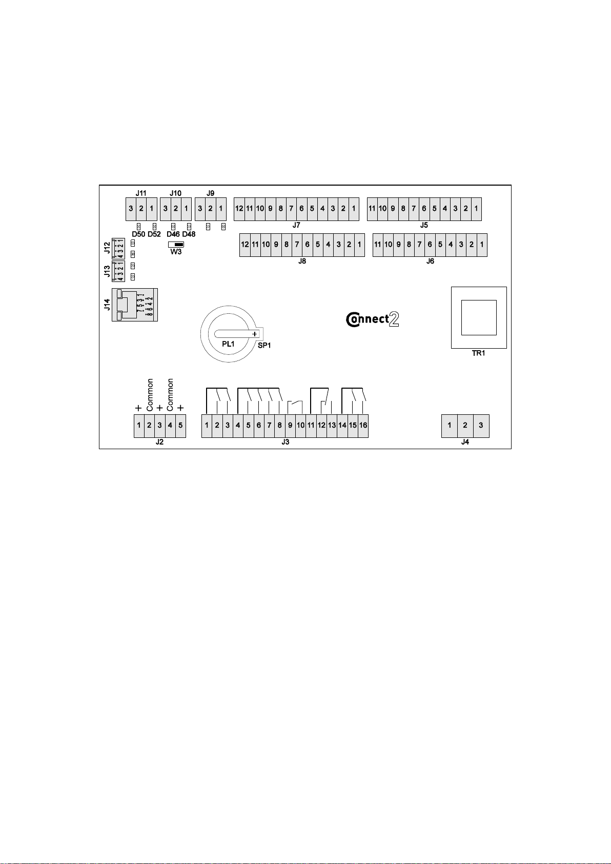
3.1 Main control board for machines with one non-reversible refrigerating circuit
SWITCH W3
End-of-line resistance for two-wire RS-485 link. The switch must
be turned to the left for the last unit on the loop and to the right for
the others.
TERMINAL BLOCK J2 (analogue outputs)
1-2 0-10 V output 1 two-way valve or three-way valve if unit type
(P2) = water-to-water.
or circuit 1 fan speed if unit type (P2) = air-to-water
or reversible air-to-water when P10 = centrifugal.
or air damper control if unit type (P2) = air-to-water
or reversible air-to-water when P10 = centrifugal and P20 = yes.
3-4 0-10 V output 2 (Compressor INVERTER if P7 = INVERTER)
4-5 0-10 V output 3 (variable speed pumps).
TERMINAL BLOCK J3 (on/off inputs)
1 Stage control common
2 Stage 1, circuit 1 control
3 Stage 2, circuit 1 control
or if P7 = INVERTER (compressor shut off order to driver)
4 Common for fans, heater and heat trace cable
5 Circuit 1, fan 1 control (and circuit 2 if intertwined coil)
6 Circuit 1, fan 2 control (and circuit 2 if intertwined coil)
7 Heater control
8 Heat trace cable control
9-10 Configurable control based on P111:
- Max. power
- Boiler
- Cooling/Heating
11 Fault output common
12 NC contact for fault output
13 NO contact for fault output
14 Common for pumps
15 Pump 1 control
16 Pump 2 or reversing valve control, circuit 1
TERMINAL BLOCK J4 (power supply)
1 230 V board power supply - Line
2 230 V board power supply - Neutral
3 Earth
TERMINAL BLOCK J5 (on/off inputs)
1-2 Motor fault, stage 1, circuit 1
2-3 Motor fault, stage 2, circuit 1
4-5 Manual reset fault, HP, circuit 1
5-6 Expansion valve fault, circuit 1
7-8 Phase controller fault
8-9 Water flow fault
10-11 Pump 1 fault
TERMINAL BLOCK J6 (on/off inputs)
1-3 Pump 2 fault
2-3 Automatic operation control
4-6 Setpoint 1/setpoint 2 selection
5-6 Heating/cooling selection if unit type (P2) = water-to-water
or fan fault if unit type (P2) = air-to-water
or reversible air-to-water
7-9 Stage 1, circuit 1 load shedding control
8-9 Stage 2, circuit 1 load shedding control
10-11 Recovery control
TERMINAL BLOCK J7 (analogue inputs)
1-2 10 K outdoor temperature sensor
2-3 10 K water inlet temperature sensor, heat exchanger 1
4-5 10 K water outlet temperature sensor, heat exchanger 1
5-6 10 K hot water temperature sensor if unit type (P2) = water-to-water
or exchanger amb. temp. if unit type (P2) = air-to-water
or reversible air-to-water
7 +24 V power supply for pressure sensors
8 0-10 V input for water inlet sensor on circuit 1
9 0-10 V input for water outlet sensor on circuit 1
10 Common for pressure sensors
11 4-20 mA remote setpoint
12 Setpoint common
4
Page 7
TERMINAL BLOCK J8 (analogue inputs)
1-2 Refrigerant temperature sensor, circuit 1
2-3 10 K suction temperature sensor, circuit 1
4-5 10 K liquid temperature sensor, circuit 1
6-7 50 K discharge temperature sensor, stage 1, circuit 1
7-8 50 K discharge temperature sensor, stage 2, circuit 1
9 +5 V power supply for pressure sensor
10 0-5 V input - HP sensor
11 0-5 V input - LP sensor
12 Common for pressure sensors
TERMINAL BLOCK J9
Link for chiller or MULTICONNECT
TERMINAL BLOCK J10
Remote control console, relay board link - AEROCONNECT
TERMINAL BLOCK J11
BMS link
TERMINAL BLOCK J12
Local console link
TERMINAL BLOCK J13
Link for additional boards
TERMINAL BLOCK J14
Ethernet link for PC
On/off input specifications: 24 V - 15 mA
On/off output specifications: 250 V - 2 mA
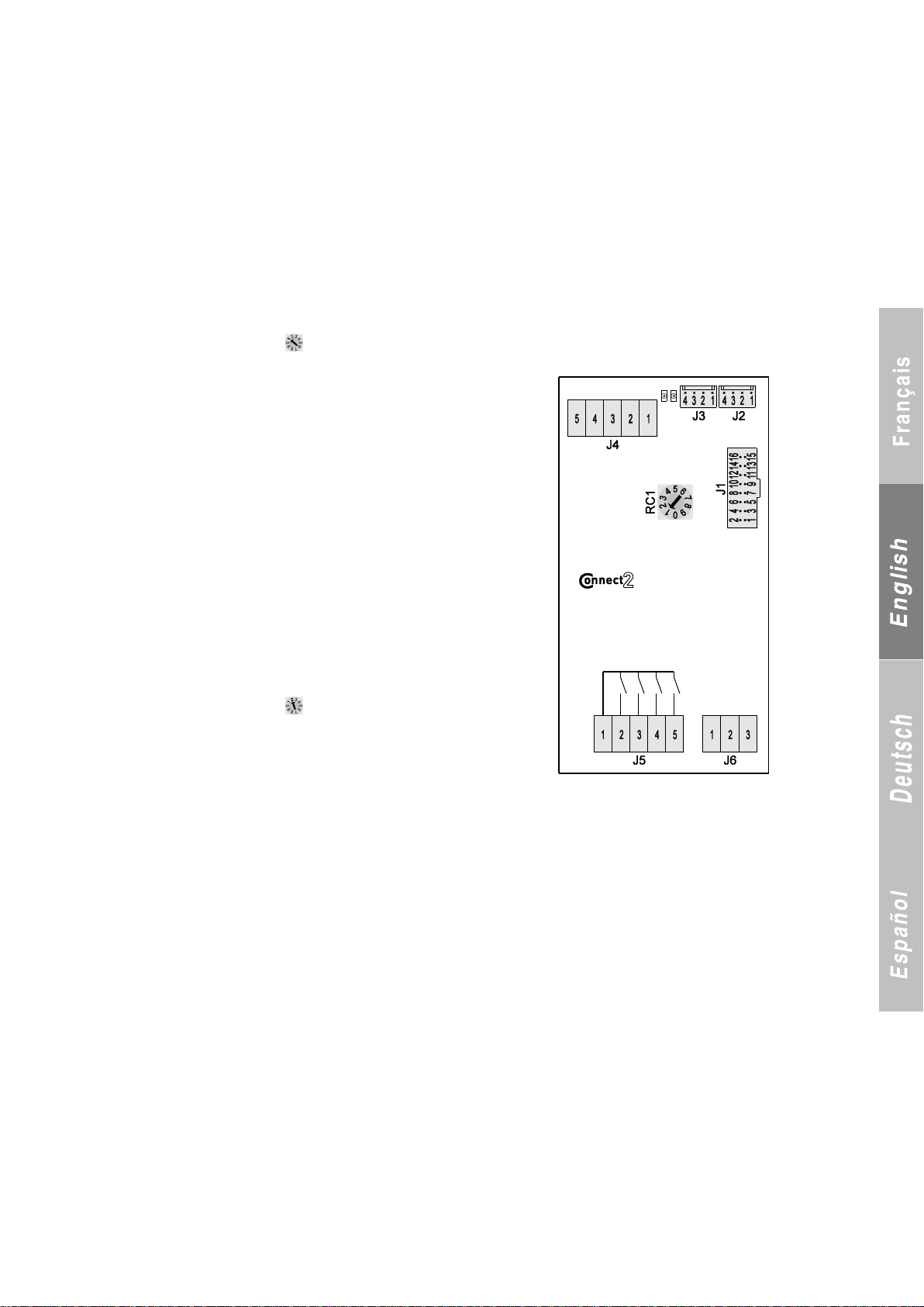
3.2 Additional board 1
3.2.1 Rotary switch set to position 1 - One circuit reversal use or recovery frost protection
TERMINAL BLOCK J1
Flash Memory connector
TERMINAL BLOCK J2
Link with motherboard or another additional board
TERMINAL BLOCK J3
Link with another additional board
TERMINAL BLOCK J4 (on/off inputs)
1-2 Heating/cooling selection input if unit type (P2) = reversible air-to-water
and number of circuits (P3) = 1
2-3 Available
4-5 Available
TERMINAL BLOCK J5 (on/off inputs)
1 Common to all outputs
2 Circuit 1 reversing valve control
3 Circuit 1 pressure balance valve control
4 Recovery frost protection heat trace cable
5 Reverse rotation control for fans
TERMINAL BLOCK J6 (analogue inputs)
1-2 Temperature sensor, coil A, circuit 1
2-3 Temperature sensor, coil B, circuit 1
3.2.2 Rotary switch set to position 2 - Use of electric auxiliary heaters
TERMINAL BLOCK J1
Flash Memory connector
TERMINAL BLOCK J2
Link with motherboard or another additional board
TERMINAL BLOCK J3
Link with another additional board
TERMINAL BLOCK J4 (on/off inputs)
1-2 Programmable input (P113)
2-3 Fault 1, electric stages
4-5 Fault 2, electric stages
TERMINAL BLOCK J5 (on/off inputs)
1 Common to all outputs
2 Electric stage 1 output
3 Electric stage 2 output
4 Electric stage 3 output
5 Electric stage 4 output
TERMINAL BLOCK J6 (analogue inputs)
1-2 Available
2-3 Available
5
Page 8
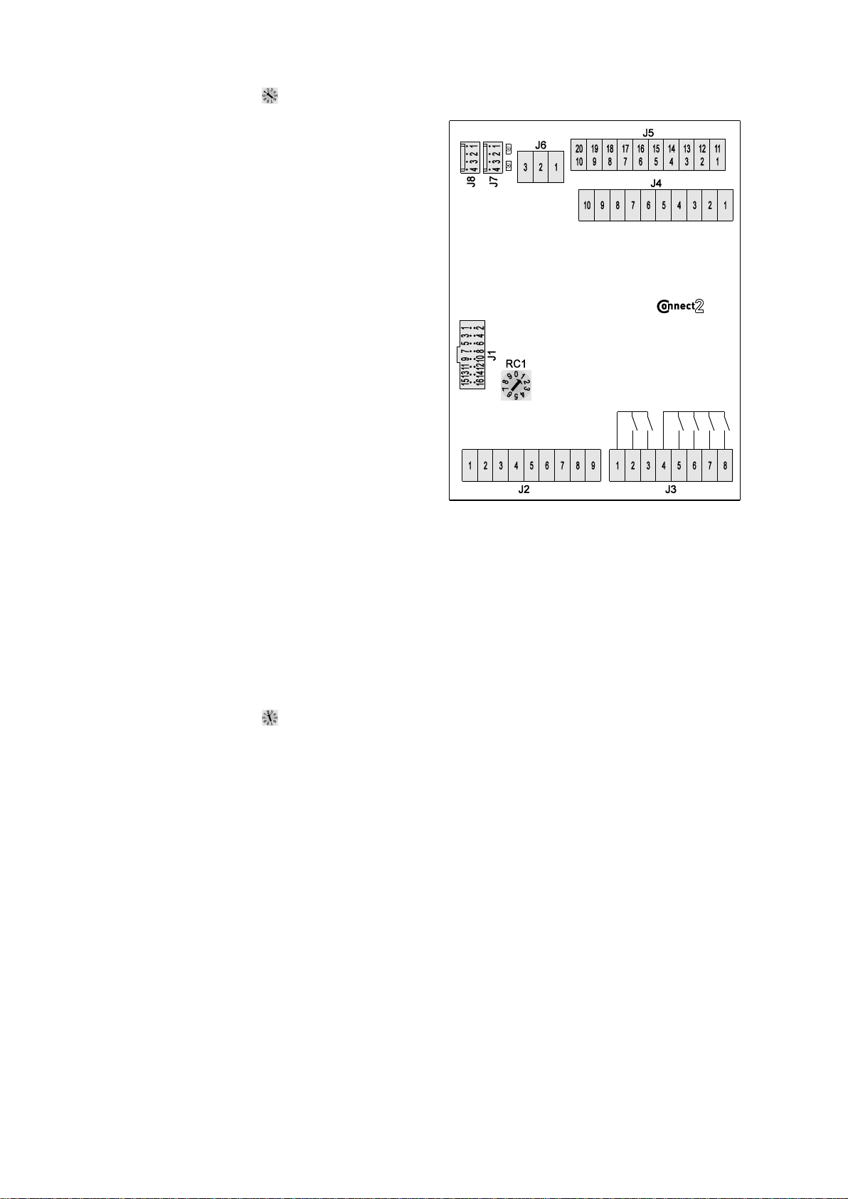
3.3 Additional board 2
3.3.1 Rotary switch set to position 1 - Two circuit use
TERMINAL BLOCK J1
Flash Memory connector
TERMINAL BLOCK J2 (on/off inputs)
1-2 Motor fault, stage 1, circuit 2
2-3 Motor fault, stage 2, circuit 2
4-5 Manual reset fault, HP, circuit 2
5-6 Expansion valve fault, circuit 2
7-8 Load shedding input, stage 1, circuit 2
8-9 Load shedding input, stage 2, circuit 2
TERMINAL BLOCK J3 (on/off inputs)
1 Common for stages 1 and 2, circuit 2
2 Stage 1, circuit 2 control
3 Stage 2, circuit 2 control
4 Common for fan stages
5 Stage 1, circuit 2 fan control
6 Stage 2, circuit 2 fan control
7 Stage 3, circuit 1 fan control if coil type
(P11) = split
or stage 1, common fan if coil type
(P11) = mixed
8 Stage 3, circuit 2 fan control if coil type (P11) = split
or stage 3, common fan if coil type
(P11) = mixed
TERMINAL BLOCK J4 (analogue inputs)
1-2 10 K water outlet temperature sensor, heat exchanger 2
2-3 10 K manifold water outlet temperature sensor
4-5 10 k refrigerant temperature sensor, circuit 2
5-6 50 K Discharge temperature 3 or 2 if
2 circuits and 1 stage per circuit (P3 =1) (stage 1, circuit 2)
7-8 50 K sensor, discharge temperature 4 (stage 2, circuit 2)
8-9 Circuit 2 suction temperature
J4-10, J5-1 Circuit 2 liquid temperature
TERMINAL BLOCK J5 (analogue inputs)
1 Common
2 Available
3 +5 V power supply for pressure sensors
4 0-5 V input for HP sensor on circuit 2
5 0-5 V input for LP sensor on circuit 2
6 0 V power supply, HP-LP pressure sensors
7 +24 V power supply for water pressure sensors
8 0-10 V input for water inlet circuit on exchanger 2
9 0-10 V input for water outlet circuit on exchanger 2
10 0 V power supply for water pressure sensors
TERMINAL BLOCK J6 (analogue outputs)
1 0-10 V output for circuit 2 fan
2 Common for outputs
3 0-10 V output for common fan, circuits 1 and 2
TERMINAL BLOCK J7
Link with motherboard or another additional board
TERMINAL BLOCK J8
Link with another additional board
3.3.2 Rotary switch set to position 2 - Two circuit reversal use
TERMINAL BLOCK J1
Flash Memory connector
TERMINAL BLOCK J2 (on/off inputs)
1-2 Heating/cooling selection input if unit type (P2) = reversible
air-to-water and number of circuits (P3) = 2
2-3 Available
4-5 Available
5-6 Available
7-8 Available
8-9 Available
TERMINAL BLOCK J3 (on/off inputs)
1 Common for reversing valves
2 Circuit 1 reversing valve control
3 Circuit 2 reversing valve control
4 Common for balance valves
5 Circuit 1 balance valve control
6 Circuit 2 balance valve control
7 Reverse rotation control for circuit 1 fans
8 Reverse rotation control for circuit 2 fans
TERMINAL BLOCK J4 (analogue inputs)
1-2 Temperature sensor, coil A, circuit 1
2-3 Temperature sensor, coil B, circuit 1
4-5 Temperature sensor, coil C, circuit 1
5-6 Temperature sensor, coil D, circuit 1
7-8 Temperature sensor, coil A, circuit 2
8-9 Temperature sensor, coil B, circuit 2
8-10 Temperature sensor, coil C, circuit 2
TERMINAL BLOCK J5 (analogue inputs)
1-2 Temperature sensor, coil D, circuit 2
3 +5 V power supply - Available
4 0-5 V input - Available
5 0-5 V input - Available
6 0 V power supply - Available
7 +24 V power supply - Available
8 0-10 V input - Available
9 0-10 V input - Available
10 0 V power supply - Available
TERMINAL BLOCK J6 (analogue outputs)
1 0-10 V output - Available
2 Common for 0-10 V output - Available
3 0-10 V output - Available
TERMINAL BLOCK J7
Link with motherboard or another additional board
TERMINAL BLOCK J8
Link with another additional board
6
Page 9
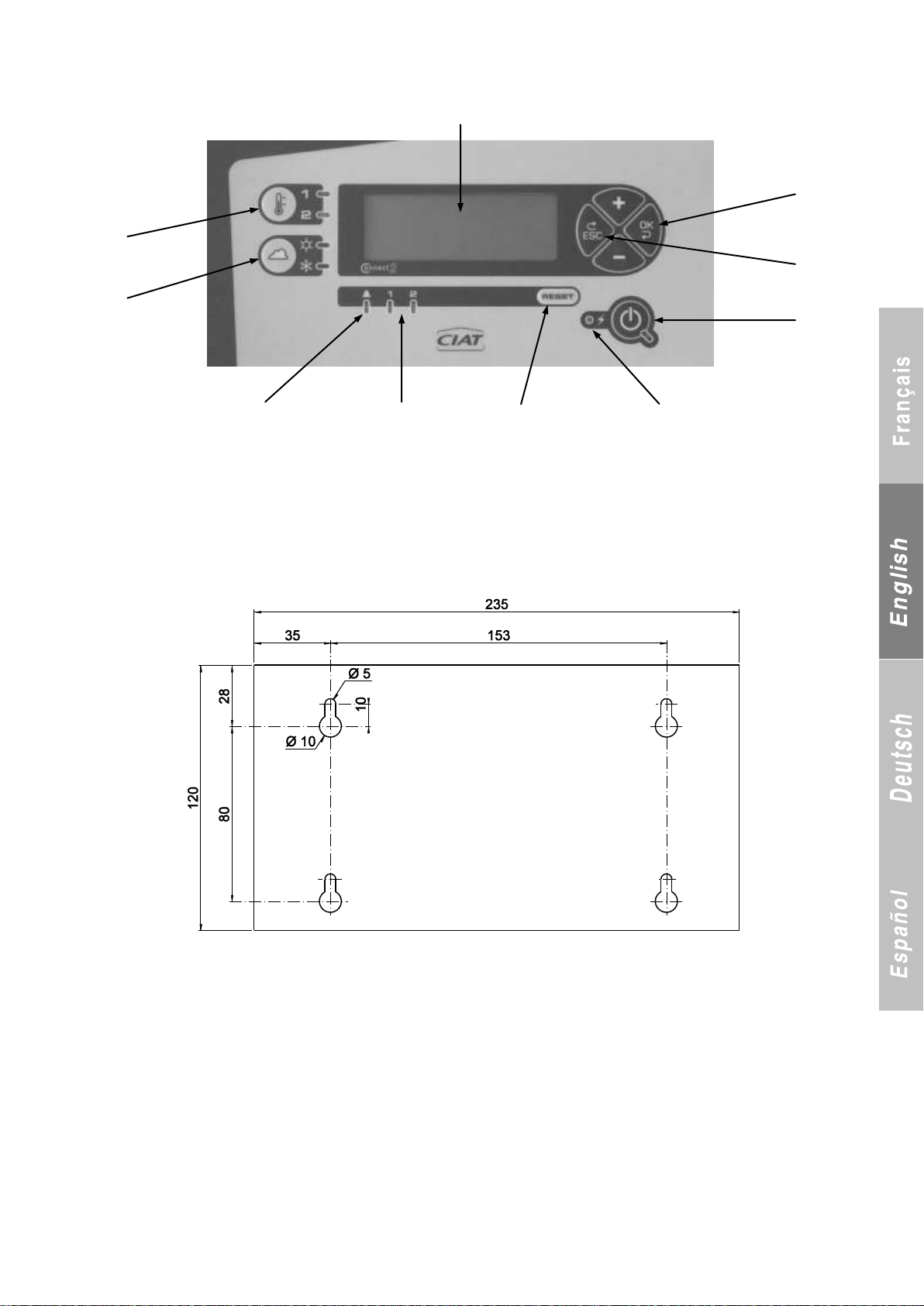
3.4 Control and display console
LCD
Setpoint 1/
Setpoint 2 button
Heating/
Cooling selection
button
Power LED
Reset
Confirm
button
Cancel
button
On/Off
button
Circuit fault
LED
General fault LED
The local console and the remote control console have the same front.
Mounting dimensions (in mm) of remote control console
Thickness: 55 mm
7
Page 10
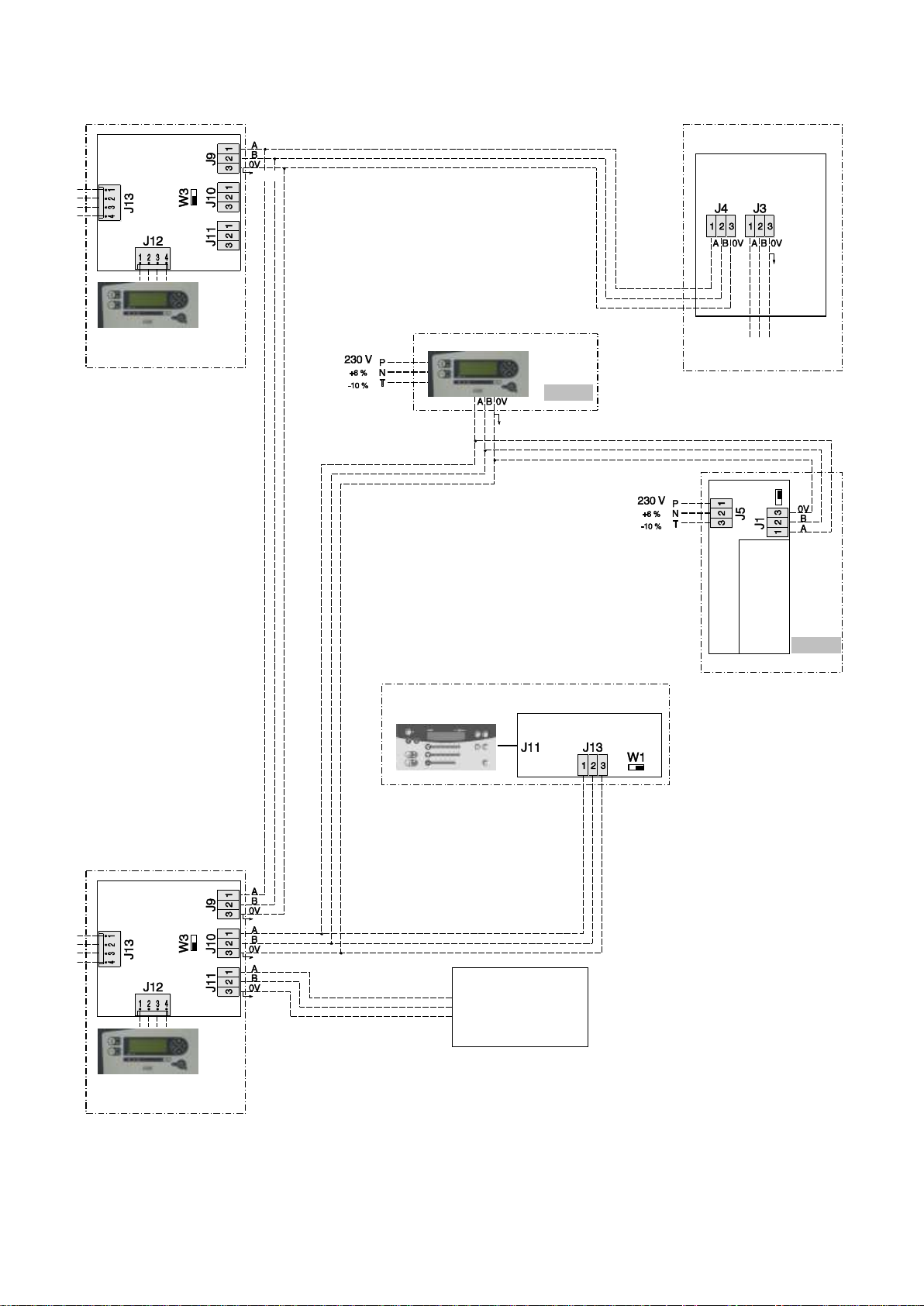
3.5 Connection via RS485 serial port for BMS or control console and Multiconnect with 500 kW module
Detail B
End of line
resistance switch
The switch is set to the right by default.
On the last machine in the loop, it must
be set to the left.
Detail A
End of line
resistance switch
Position of switch when only one
option is connected to the RS-485
output on the main board
Position of switch when several options
are connected to the RS-485 output on
the main board
RS-485 PLC
BMS
2-wire RS-485
Max. length:
1000 m
Main relay
board
Additional
relay board 1
See detail A
Optional
Installed on unit
Shield
To
additional
board
CONNECT 2 main board
Unit 2
Local console
See detail B
Shield
Shield
Installed on unit
Shield
To
additional
board
CONNECT 2 main board
Unit 1
Local console
See detail B
Remote control console
Shield
Optional
MULTICONNECT
main board
Shield
RS-485 link to BMS
(Modbus protocol)
AEROCONNECT board
UNIT
Local console
For connection to a CMS, refer to document 3991049.
Identification of Modbus connection terminals
1 →A or +
2 →B or –
3 →Earth (shield)
8
Page 11

3.6 Relay boards
Main
board
Additional
board
Dimensions of boards
Main board
Width: 105 mm
Length: 208 mm
Thickness: 65 mm
Mounting centre distance:
Additional board
Width: 60 mm
Length: 157 mm
Thickness: 40 mm
Mounting centre distance:
50 × 147 mm
The dry contacts on the relay boards make it possible to remotely view the states of the stages that are on and all the fault states on the unit.
A 230 V +6% -10% power supply must be provided for each relay board.
Connect terminal block J1 (1-2) on each relay board to terminal block J10 on the main board.
If the link between the motherboard and the relay board is defective, contact 1-2 on the relay board will chatter at a rate of one change in
state per second.
These are NO dry contacts.
Terminal block layout:
1-2 Permanent fault, water flow rate
3-4 Permanent fault, frost protection (liquid or water), circuit 1
5-6 Permanent fault, HP 1 (sensor or manual)
Main 7-8 Permanent fault, LP 1
relay board: 9-10 Permanent fault, discharge temperature 1 or 2
1 circuit 11-12 Stage 1 status, contact closed, stage ON
13-14 Stage 2 status, contact closed, stage ON
15-16 Motor fault, stage 1, contact closed motor fault
17-18 Motor fault, stage 2, contact closed motor fault
19-20 Fan fault
21-22 Permanent fault, frost protection (refrigerant or water), circuit 2
Additional 23-24 Permanent fault, HP 2 (software or manual)
relay board 1 25-26 Permanent fault, LP 2
2 circuits 27-28 Permanent fault, discharge temperature 3 or 4
If P3 = 2 29-30 Stage 3 status, contact closed, stage ON
31-32 Stage 4 status, contact closed, stage ON
33-34 Motor fault, stage 3
35-36 Motor fault, stage 4
19-20 Fan fault
21-22 Fault, 1 or 2 electric stages
Or 23-24 Operation of auxiliary heaters, stage 3 or 4
Additional 25-26 Operation of auxiliary heaters, stage 1 or 2
relay board 1 27-28
circuit with aux. heaters 29-30
if P3 = 1 when P22 = Yes 31-32
33-34
35-36
4 DESCRIPTION
4.1 Main board
Main board for units with one non-reversible refrigerating circuit:
Analogue inputs:
Acquire signals measured by temperature sensors.
Acquire signals measured by pressure by sensors.
On/Off inputs:
Acquire operating state signals from surrounding
electromechanical components.
Actions:
Comparison of setpoint and water temperature to calculate which
stages are to be turned on or off.
Management of the protections for the machine‟s self-adjusting
operation.
4.2 Expansion (additional) boards 1 and 2
These boards are used for units with two reversible refrigerating circuits.
They manage the inputs/outputs on the second circuit or required for reversing the circuits.
Analogue inputs:
Acquire signals measured by temperature sensors.
Acquire signals measured by pressure by sensors.
On/Off inputs:
Acquire operating state signals from surrounding
electromechanical components.
Outputs:
Control stage control.
Pump control.
General fault.
The board also features:
- An “end-of-line resistance” switch.
Outputs:
Control stage control.
9
Page 12
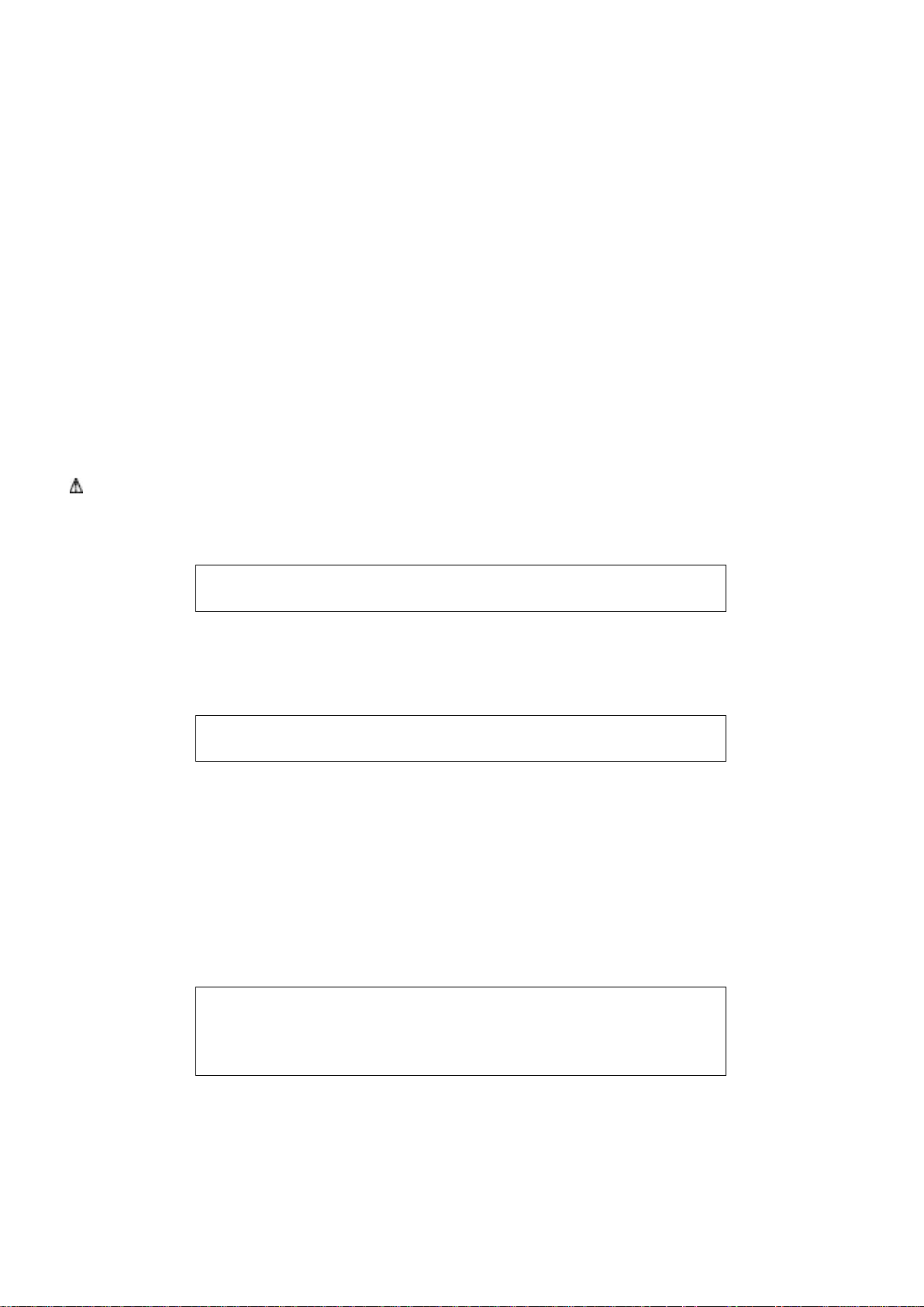
4.3 Man-Machine Communication
C O N S O L E
L O C K E D
C O N S O L E
U N L O C K E D
C O N T R O L L E R I N L E V E L x
14- 1 ACC E S S T O L E V E L 2
14- 2 ACC E S S T O L E V E L 3
Local console:
- The controls on the local console are enabled regardless of the value of P103.
- Acknowledgment of faults is possible.
Remote control console:
- All parameters may be read depending on the authorised access level.
- All unit controls are enabled if P103 = remote or BMS.
- In this case, the following parameters may be accessed for modification:
- On/Off.
- Cooling/Heating.
- All adjustment parameters are locked, depending on the authorised access level, except for the first 11 if P103 = local.
- Acknowledgment of faults is not possible.
- Test mode is possible.
BMS:
- All parameters (except P100, P103, P104 and P105) are accessible in read mode..
- All parameters (except P1 to P99, P100, P103, P104 and P105) are accessible in write mode. However, access to parameters P1 to P99 is
possible when P99 is unlocked on the machine‟s local console.
- Acknowledgment of faults is not possible.
NOTE: All the registers (see communication protocol) appear regardless of the value of P103.
To enable write mode, P103 must be set to „remote or BMS‟.
To be able to switch between heating and cooling, P199 must be set to „cooling/heating‟ via the console.
To be able to switch between setpoints 1 and 2, P120 must be set to „2‟ via the console.
Locking the console:
Available only on the local console on the unit.
The factory setting for the console is „unlocked‟.
The lock status is saved in the event of a mains power failure.
If lock mode is enabled while modifying a parameter, any
modifications made are aborted and the controller is reset to its
All modifications from the local console are then inhibited.
Any attempts to make modifications will cause the above message to appear for 3 seconds.
To unlock the console, simultaneously hold down the + and - buttons for 5 seconds. The following message appears on the screen for
3 seconds:
initial value.
To lock the console, simultaneously hold down the + and –
buttons for 5 seconds (possible in any menu on the console).
The following message appears on the screen for 5 seconds then
machine state reappears.
5 ACCESS LEVELS
CONNECT 2 features three parameter access levels:
- Level 1: Users
- Level 2: Technicians/Maintenance
- Level 3: CIAT Technicians (full access)
5.1 Selecting an authorised access level
Authorised access levels are selected in menu 14 (ACC. LEVEL SELECT.). The following screen appears:
- Level 3 provides automatic access to all levels (CIAT technicians).
- Level 2 provides access to levels 1 and 2 only (Technicians/Maintenance and CIAT technicians).
- Level 1 provides access to level 1 only (all users).
5.2 Accessing the various access levels
5.2.1 Restricting access to level 1 only
- Access level 2 is the default access level.
- If you are in a higher level and you want to restrict access to level 1 only, simultaneously hold down the ESC and OK buttons for 10 seconds.
10
Page 13

- No password is needed to access level 1. The setpoint adjustment range is + or – 5 K lower than in the higher access levels.
L E V E L 2
ACC E S S C O D E
* * * *
L E V E L 2
NEW ACC E S S C O D E
* * * *
L E V E L 2
N E W C O D E S A V E D
L E V E L 3
ACC E S S C O D E
* * * *
14- 1 ACC E S S T O L E V E L 2
ACC E S S T O L E V E L 2
O N L Y
Y E S / N O
W R O N G C O D E
- The restriction messages remain displayed in access level 1. Operating messages in optimised mode are visible only in access levels 2 and 3.
- Restriction of access to level 1 only is stored in memory in the event of a mains power failure.
5.2.2 Access to level 2:
- A numeric code must be entered to access level 2:
- The following menu for entering this code appears when LEVEL 2 is selected:
- Using the + and –buttons, replace this first symbol (*) by the first character in the code and press Enter . Do the same for the second, third
and fourth symbols. When the last character is entered and Enter is pressed, the following menu appears:
- To select a new access code, proceed as described above. When the last character is entered and Enter is pressed, the screen displays the
menu below followed by the main menu.
- If you do not want to change the level 2 access code, press ESC to exit the new access code menu and go back to the main menu.
- If you have changed your access code but have forgotten it, you can reset it to the original code by entering the LEVEL 2 ACCESS CODE
menu and simultaneously holding down the + and Reset buttons for 10 seconds.
5.2.3 Access to level 3
A non-modifiable numeric code must be entered to access level 3:
- The following menu for entering this code appears when LEVEL 3 is selected:
- Using the + and –buttons, replace this first symbol (*) by the first character in the code and press Enter. Do the same for the second, third
and fourth symbols. When the last character is entered and Enter is pressed, the main menu appears.
5.2.4 Restricting access from level 3 to level 2
To restrict access from level 3 to level 2 only, go to the following menu:
Press Enter. The following menu appears:
To restrict the controller to access level 2, select „Yes‟ and press Enter.
5.2.5 Displaying the access codes on the controller after incorrectly entering the access codes:
- The digits in the access codes are replaced by the* symbol. When the + or - buttons are pressed, this symbol is replaced by the digit 0. The
digits in the code can then be selected using the + or - buttons.
The * symbol appears when the digit is confirmed by pressing Enter.
- The following message appears for 5 seconds if the access code is not entered correctly:
11
Page 14
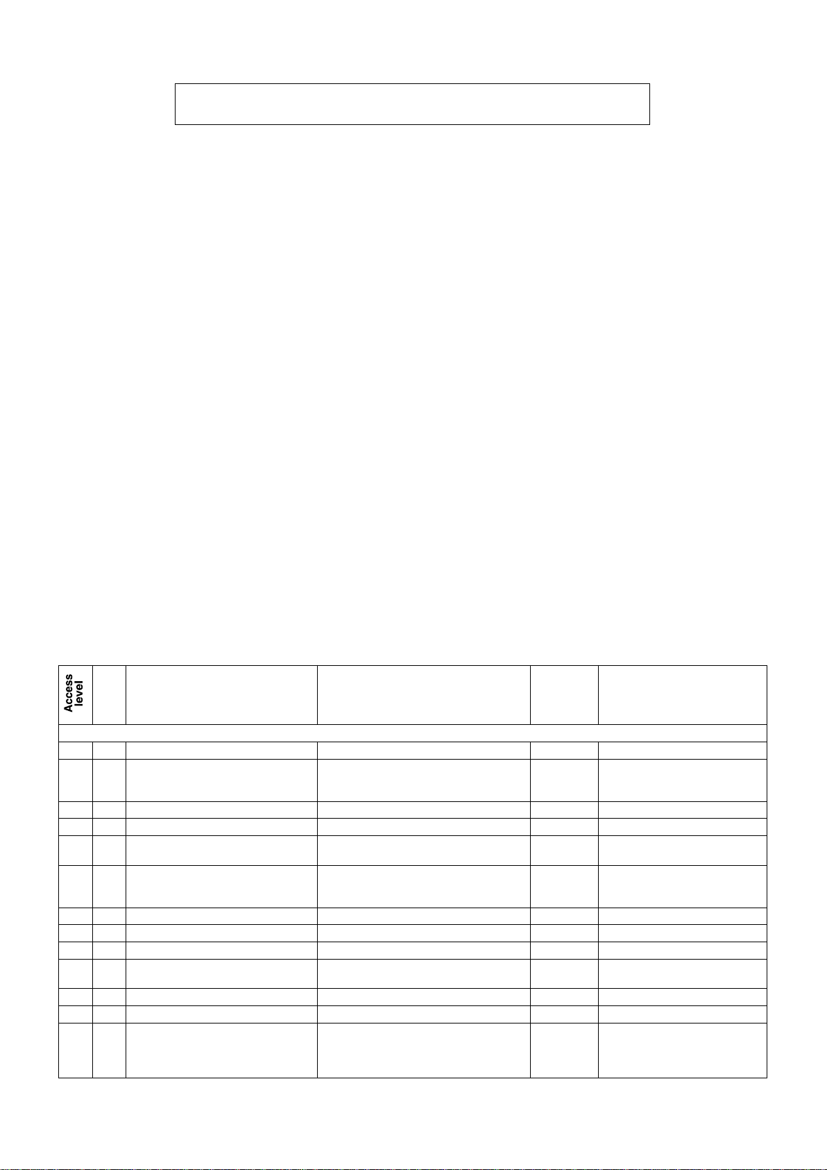
- When an access level is changed, the following message is displayed for 5 seconds:
ACC E S S L E V E L x
No.
Description
Setting
Default
Display conditions
CONFIGURATION OF THE MACHINE
3
1
Refrigerant type
R407C, R134a, R404a, R22, R410A
R410 A
3
2
Unit type
1-Water-to-Water
2-Air-to-Water
3-Reversible air-to-water
2
3
3
Number of circuits
1-2 1
3
4
Number of stages on circuit 1
1 or 2 1
3
5
Number of stages on circuit 2
0, 1, 2
0 if P3 = 1
1 if P3 = 2
Hidden if P3 = 1
3
6
Number of evaporators
1 if P3 = 1,
1 if P3 = 1 and P2 = air-to-water
2 if P3 = 2
1 if P3 = 1
2 if P3 = 2
3
7
Compressor supplier
Maneurop - Copeland - Inverter
Copeland
3
8
Heat exchanger suppliers
CIAT - Swep - Swep double - Alfa laval
CIAT
3
10
Fan type
Centrifugal - Propeller – Available pressure
Propeller
If P2 = 2, 3
3
11
Coil type
Intertwined - Split - Mixed
Intertwined
If P3 = 2, P10 = pressure ,
P2 = 2, 3
3
12
Pressure balance solenoid valve
No - Yes
No
If P2 = reversible air-to-water
3
13
Tandem type
Balanced Yes/No
Yes
3
14
Number of coil sensors per circuit
1.2 or 4
1 if P3
(No. of
circuits) = 1
2 if P3 = 2.
5.3 Configuring access levels on the controller
- All three access levels on all the boards are accessible for a
total of 20 hours of „on‟ time after the controller is first turned on.
During this period any defective boards may be removed and their
replacement boards configured and checked to ensure correct
operation of machine.
This time period will be automatically cancelled if a user switches
to level 1 or level 2 before it ends.
When the time period ends, level 2 will be authorised unless the
person commissioning the system chooses to restrict access by
the end user to level 1.
- If access level 3 is authorised in order to adjust the machine
parameters and, for indeterminate reasons, it is left accessible to
all users, only level 2 access will be possible after a period of 4
hours.
- Commissioning of the machine can be prohibited simply by
setting parameter P99 to „No‟ in level 2.
Only those with the level 2 access code may re-enable
commissioning of the machine.
5.4 Management of the numeric codes for accessing levels 2 and 3
- Access to level 3 is direct for anyone with a PC running the program needed to communicate with CONNECT 2 and who connects to
the board.
- Access to levels 2 and 3 is restricted to CIAT Service technicians. Please contact your local CIAT Service office.
5.5 Classification of the menus and their functions
Level 1:
Menu:
Setpoint, machine status, measured values, control parameters,
operation parameters, fault memory, hourly scheduling,
communication and access level selection.
Function:
all functions accessible via the console: On/Off, Reset,
Heating/Cooling selection; Setpoint 1/2 selection
Level 2:
Menu: all level 1 menus + test mode and master/slave
operation
Level 3:
Menu: all level 2 menus + electronic expansion valve
6 LIST OF PARAMETERS
Access levels: 1 = Access to User parameters (level 1 parameters only)
2 = Access to visible and editable parameters (level 1 and 2 parameters). EDITABLE numeric code.
3 = Access to CIAT technician parameters (level 1, 2 and 3 parameters). UNEDITABLE numeric code
12
Page 15
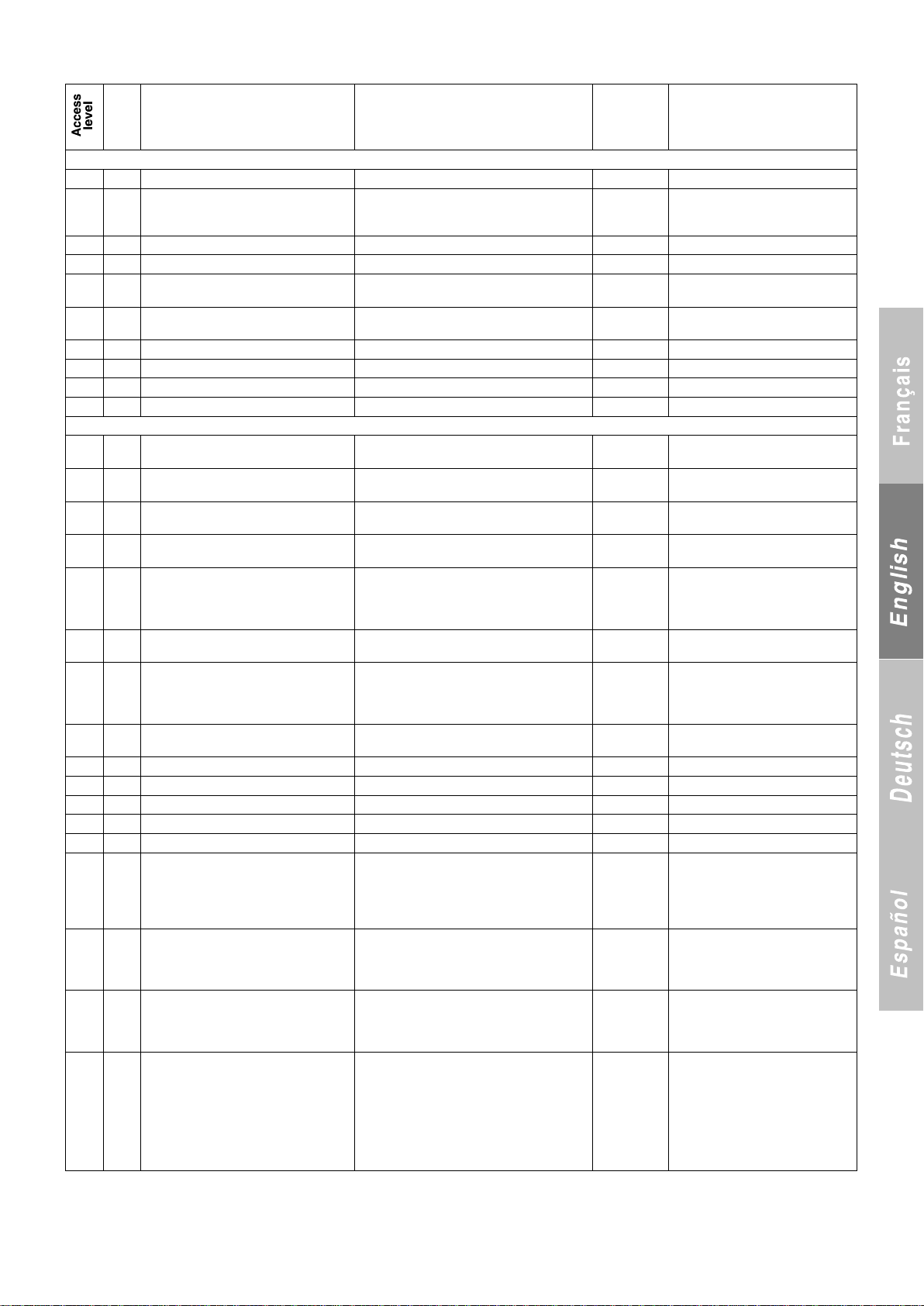
No.
Description
Setting
Default
Display conditions
OPTION
2
20
All-season operation
No - Yes
Yes
If P2 = 2, 3
2
21
Variable speed drive
1 - Without
2 - With acoustic optimisation
3 - With energy optimisation
Without
If P2 = 2, 3 P10 = Propeller
Value 3 accessible only
if P42 = CIAT
2
22
Electric auxiliary heaters
No - Yes
No
If P2 = 1 or 3
2
25
Number of pumps delivered by CIAT
0-1-2 if P2 = 2 and 0-1 if P2 = 3
0
Visible if P2 = 2 or 3
2
26
0-10 V configurable output
2WV - 3WV
2WV
2WV, Visible if P2 = water/water and P3 = 1
3WV, Visible if P2 = water/water
2
27
Pump controlled by operation of boiler
Yes/No
No
Visible if P2 = 3
and P111 = Boiler
2
28
Master/slave control of two machines
Yes/No
No 2
29
Total recovery
Yes/No
No
If P2 = 2
2
29.1
Frost protection during heat recovery
Yes/No
No
Breakdown
3
30
High pressure, HP 1 sensor
10 to 50 b (resolution: 0.1)
34
45 with R410A
3
31
Low pressure, HP 1 sensor
-1 to 10 b (resolution: 0.1)
-0.5
0 with R410A
3 32
High pressure, HP 2 sensor
10 to 50 b (resolution: 0.1)
34
45 with R410A
If P3 = 2
3
33
Low pressure, HP 2 sensor
-1 to 10 b (resolution: 0.1)
-0.5
0 with R410A
If P3 = 2
3
36
High pressure, LP 1 sensor
10 to 50 b (resolution: 0.1)
34
45 with R410A
17.3 b if
P42 = CIAT
3
37
Low pressure, LP 1 sensor
-1 to 10 b (resolution: 0.1)
-0.5
0 with R410A
3
38
High pressure, LP 2 sensor
10 to 50 b (resolution: 0.1)
34
45 with R410A
17.3 b if
P42 = CIAT
If P3 = 2
33
39
Low pressure, LP 2 sensor
-1 to 10 b (resolution: 0.1)
-0.5
0 with R410A
If P3 = 2
3
42
Electronic expansion valve
No/ALCO/CIAT
No
3 43
Superheat protection
Yes/No
No
3
44
Minimum superheat
0 to 5 K (resolution: 0.1)
0.5 K
If P43 = Yes
3
45
Maximum overheating
10 to 20 K (resolution: 0.1)
15.0 K
If P43 = Yes
3
50
SCP (runtime + off)
3 to 10 min. (resolution: 1)
5
3
51
Discharge temperature limit
60 to 145°C (resolution: 1)
145°C if Cop.**
135°C if Man.**
125°C if
R410A and
P7 = Cop**
3
52
Water line frost protection limit
-25 to 6°C (resolution: 0.1)
2 if P1 = R22,
4 if P1 = 407C,
R134a, R404
and 3 if R410A
P52 2°C if P22 = Yes
3
53
Δ for refrigerant frost protection
limit/P52
2 to 15 K (resolution: 0.1)
10
5 with R410A
7 if P7 =
INVERTER
Refrigerant frost protection limit =
P52 - P53
3
54
HP fault threshold
15 to 45 b (resolution: 0.1)
27.5 if P1 =
R407C or R22
19 if P1 =
R134a
24 if P1 =
R404a
40.2 b if
R410A
**Cop. = Copeland; Man. = Maneurop
13
Page 16
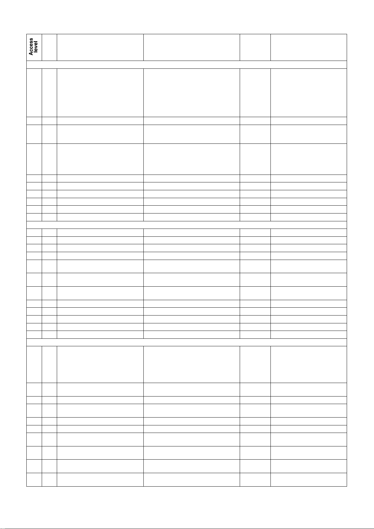
No.
Description
Setting
Default
Display conditions
Breakdown (continued)
3
55
LP fault threshold
0.1 to 5 b (resolution: 0.1)
If P2 = 3: 0.5 b
If P2 ≠ 3:
(1.5 b if P1 =
R22, R407C,
R404a) and
(0.5 b if P1 =
R134a)
2.5 b with R410A
3
58
LP slope factor
0 to 5 b (resolution: 0.5)
1
If P2 = 1, 2 or 3
3
59
Water outlet temperature slope factor
0 to 1 (resolution: 0.1)
0 if P2 = 1
0.5
if P2 = 2 and 3
If P2 = 1, 2, 3
3
63
Minimum HP limit
5 to 25 b (resolution: 0.1)
13 if
R22-R407C
8b with R134a
15 b with R404a
18 b with R410A
If P2 = water-to-water
3
64
Optimised frost protection
Yes - No
Yes
If P1 = R410A, P2 = 2 or 3
3
65
Delta T/Heat exchanger type
0 - 10 0 If P64 = Yes: confirm
3
66
Start-up time delay
0 to 300 seconds
120s
If P7 = INVERTER
3
67
Oil warming time delay
Yes - No
Yes
If P7 = INVERTER
3
99
Parameter locking
No - Yes
No
CUSTOMER CONFIGURATION
2
100
Language
F - GB - D - SP - I
F
2 101
Date
DAy/MOnth/YEar
2 102
Time
HOurs/MInutes
1
103
Control type
Local - remote (BMS)
Local
2
108
Pump 2 control
Depending on control mode
Depending on On/Off if P2 = 1
Depending on
On/Off
Visible if P2 = 1
2
109
Pump 2 ‘on’ time delay
15 to 90 seconds (resolution: 5 seconds)
15
Visible if P2 = 1
and P108 = f (Control)
2
111
Configurable output
Max. power/Boiler/Cooling-heating / Helping on
all faults on air-to-water only
P max
2
112
Number of electric stages
1 to 4 2 Visible if P22 = Yes
2
113
Configurable input
Disabled/Load shedding/Override
Disabled
Visible if P22 = Yes
3
115
Exchanger frost detection enabled
Yes - No
Yes
Visible if P2 = 1, 2, 3
3
116
AEROCONNECT LINK
Yes - No
No
Setpoint Management
1
119
Operating mode
1 - Cooling
2 - Heating
3 - Cooling/heating via console
4 - Cooling/heating via on/off input
5 - Automatic cooling/heating based on outdoor
temperature
Cooling
If P2 = 1 or 3 = All
If P2 = 2 = Cooling only
1
120
Number of setpoints
1 - 2 via console - 2 via on/off input -
3 Setpoint managed by 4-20 mA signal
1
1
121
Cooling setpoint 1
P52 + 1 K at 30°C (resolution: 0.1)
10
If P2 = 1, 2 or 3 P119 ≠ Heating
1
122
Cooling setpoint 2
P52 + 1 K at 30°C (resolution: 0.1)
12
If P120 = 2, P2 = 1, 2 or 3,
P119 ≠ Heating
1
123
Heating setpoint 1
20 to 60°C (resolution: 0.1)
40
P119 ≠ Cooling
1
124
Heating setpoint 2
20 to 60°C (resolution: 0.1)
35
P119 ≠ Cooling, P120 = 2
1
125.1
Low setpoint (4-20 mA) during cooling:
P52 + 3 K at 30°C
P52 + 3
Displayed if P120 = 3 and in cooling
mode
1
125.2
Low setpoint (4-20 mA) during heating:
10 to 60°C
20
Displayed if P120 = 3 and in heating
mode
1
126.1
High setpoint (4-20 mA) in cooling mode:
P125.1 ± 5 K at 30°C with minimum value of
P52 + 3
20
Displayed if P120 = 3 and in cooling
mode
1
126.2
High setpoint (4-20 mA) in heating mode:
P125.2 ± 5 K at 60°C with minimum value of 10°C.
40
Displayed if P120 = 3 and in heating
mode
14
Page 17
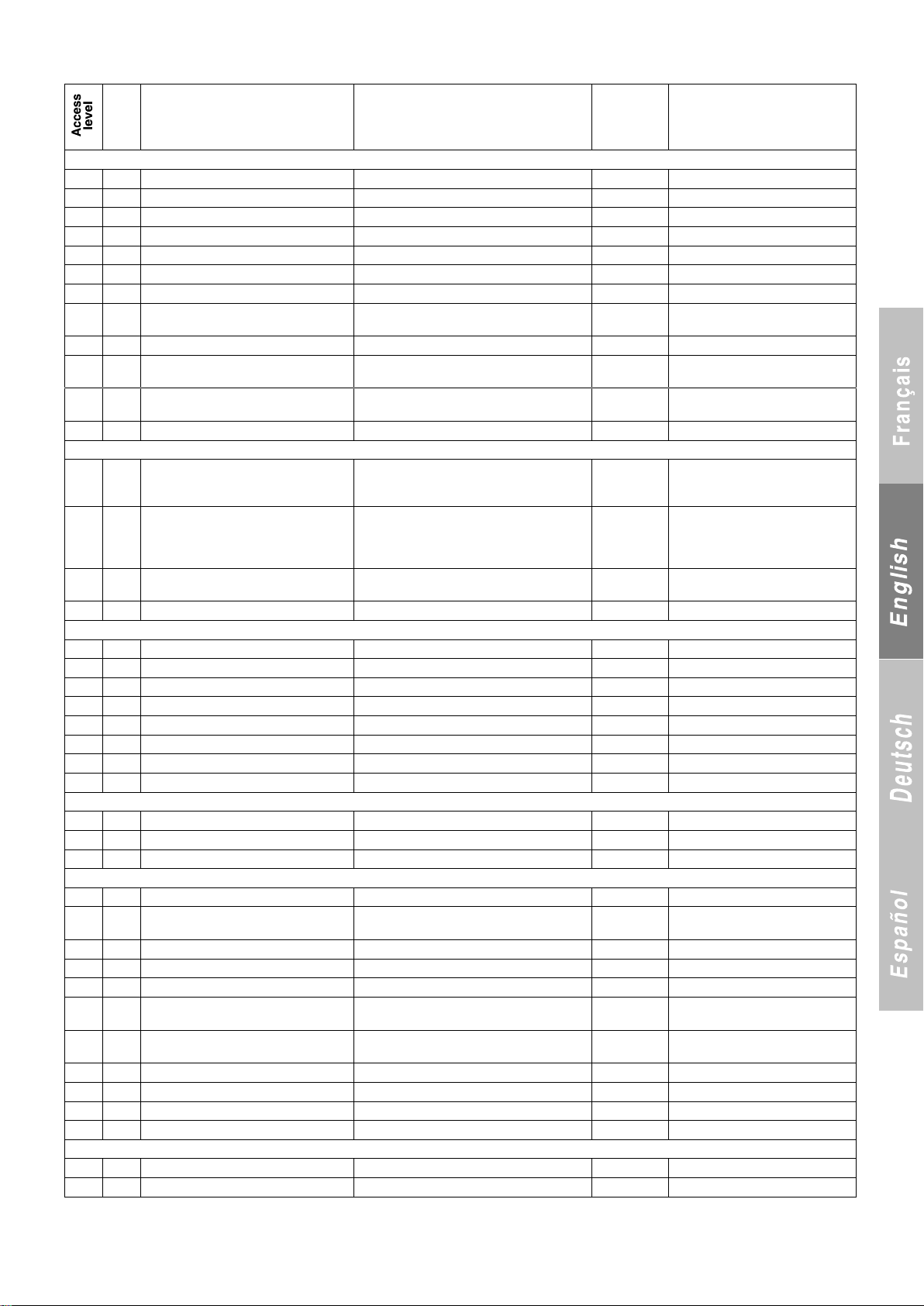
No.
Description
Setting
Default
Display conditions
Setpoint Management (CONTINUED)
1
127
Cooling setpoint adjustment = f (out. temp.)
No - Yes
No
If P2 = 1, 2 or 3 and P119 ≠ Heating
1
128
Drift start
-20 to 55°C (resolution: 1)
25
If P127 = Yes
1
129
Drift end
P128 + 5 K at 60°C (resolution: 1)
35
If P127 = Yes
1
130
Maximum setpoint at end of drift
P52 + 1 K at 30°C (resolution: 0.1)
15
If P127 = Yes
1
131
Heating setpoint adjustment = f (out. temp.)
No - Yes
No
If P2 = 1 or 3 and P119 ≠ Cooling
1
132
Drift start
-20 to 55°C (resolution: 1)
15
If P131 = Yes
1
133
Drift end
-25 to P132 - 5 K (resolution: 1)
5
If P131 = Yes
1
134
Maximum setpoint at end of drift
Highest setpoint if P120 ≠ 1 or setpoint if P120 =
1 at 60°C (resolution: 0.1)
P123
If P131 = Yes
1
135
Minimum boiler drift setpoint
30 to 55°C
50°C
If P111 = Boiler
1
136
Maximum air temperature in automatic
heating mode
- 5 to 25°C (resolution 1)
16
If P119 = 5
1
137
Minimum air temperature in automatic
cooling mode
P136 + 2 to 40°C (resolution: 1)
20
If P119 = 5
2
141
Control mode
1- Return
3- Water supply
4- Supply with compensation
1
2
142
Water loop winter protection
No - Yes
No
Visible if P2 = 1 and P141 = 1 and
heating mode
Visible if P2 = 1 and cooling mode
Visible if P2 = 2 or 3
2
143
Stage differential
0.5 to 5 K (resolution: 0.5)
2
1.5
If P141 = 1, 2
if P7 = INVERTER
2
144
Interstage differential
0.5 to 5 K (resolution: 0.5)
1.5
Supply with compensation by return
2
145
P coefficient
0.3 to 2 (resolution: 0.1)
1
If P141 = 3, 4 and P7 ≠ INVERTER
2
146
I coefficient
0 to 1 (resolution: 0.1)
0
If P141 = 3, 4 and P7 ≠ INVERTER
2
147
D coefficient
0 to 1 (resolution: 0.1)
0
If P141 = 3, 4 and P7 ≠ INVERTER
2
148
T coefficient
10 to 240 seconds (resolution: 10)
60
If P141 = 3, 4 and P7 ≠ INVERTER
2 150
Compensation of coefficient
0.1 to 1 (resolution: 0.1)
0.5
If P141 = 4
2
151
Compensation of time
5 to P148-2 (resolution: 1)
10
If P141 = 4
For storage control (CRISTOPIA)
3
154
Storage
Yes/No
No
If P119 ≠ 2, P120 ≠ 1 and P120 ≠ 4
3
155
ΔT of control
0.5 to 10°C (resolution: 0.5)
5
If P154 = Yes
Defrosting
3
157
Temperature at start of defrosting
-5 to 0°C (resolution: 0.5)
-2
If P2 = 3
3
158
Temperature at end of defrosting
10 to 30°C (resolution: 1)
15 if R407C
otherwise 25
If P2 = 3
3
159
Frosting time calculation
Fixed time Optimised
Optimised
If P2 = 3
3
160
Fixed time
30-45-60
45
If P2 = 3
3
161
Coil frosting factor
0 to 2 (resolution: 0.01)
0.3
If P159 = Optimised
3
162
DTD correction based on outdoor
temperature
0 to 1 (resolution: 0.01)
0.2
If P159 = Optimised
3
163
CP off time delay for defrosting cycle
0 to 5 min.
60s
P2 = 3
if P7 ≠ INVERTER
3
164
ΔP interlocking ventilo HP
1 to 20 b (resolution: 0.5)
2
If P2 = 3, (P HPR = P54 - P164)
3
165
DHP differential
1 to 5 b (resolution: 0.5)
2
If P2 = 3
3
166
Defrosting HP control coefficient
1 to 5 b (resolution:1)
3
If P21 ≠ 1
Charge limit
2
171
Maximum return temperature, stage 2
20 to 50°C (resolution: 1)
35
If P4 + P5 ≥ 2 and P119 ≠ Heating
15
Page 18
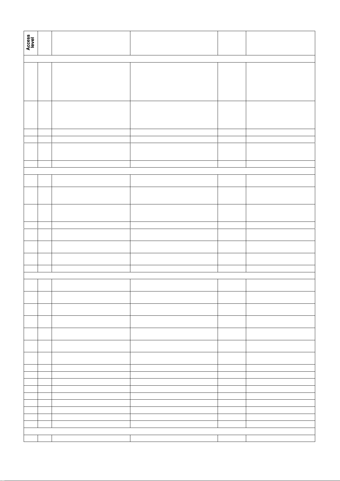
No.
Description
Setting
Default
Display conditions
FAN MANAGEMENT
2
180
Number of HP control stages per circuit
1 to 2 if P3 = 1
2 to 4 if P3 = 2 and P11 = intertwined
2 or 3 if P3 = 2 and P11 = split
3 if P3 = 2 and P11 = mixed
1 if P3 = 1
2 if P3 = 2 and
P11 = intertwined
2 if P3 = 2 and
P11 = split
3 if P3 = 2 and
P11 = mixed
Visible if P2 = 2 or 3 +
P10 = propeller
2
181
HP control setpoint
12 to 17 b (resolution: 0.5) if P1 = R407C or R22
14 to 20 b (resolution: 0.5) if P1 = R404a
7 to 13 b (resolution: 0.5) if P1 = R134a
19 to 27 b (resolution: 0.5) if P1 = R410A
13.4 to 27 b if P7 = INVERTER
12
14
7
19
Visible if P2 = 3 or P2 = 2 +
P10 = propeller
2
182
Outdoor air temperature, forced HP
10 to 40 (resolution: 1)
25
Visible if P2 = 3 or 2 + P10 = propeller
2
183
Stage differential, HP control
2 to 8 b (resolution: 0.5)
4
Visible if P2 = 3 or 2 + P10 = propeller
2
184
Interstage differential, HP control
0.5 to 3 (resolution: 0.5)
2 to 4 (resolution: 0.5)
1
3
Visible if P2 = 3 or 2 +
P10 = propeller
If P180 = 1 (Low noise function)
HIGH PRESSURE CONTROL
3
191
Low Noise operation
Yes - No
No
If P1 = R410A and P2 = 2, 3 or 4 and
P180 = 1
2
192
Max. fan speed threshold
5 to 10 V
8.0
5.6 V if P7 =
INVERTER
- If P7 ≠ Inverter and P10 = Pressure
(P21 = 2 or 3, P180 = 1 and hidden)
If P7 = Inverter and P21 = Yes
3
193
Shifting of HP setpoint during total recovery
5 to 14 (resolution: 0.5)
8 if P21 = 1
12 if P21 = 2
or 3
If P29 = Yes
3
195
ΔP
0.1 to 1 b (resolution: 0.1)
0.3
If P4 = P5 ≠ 1
3
196
ΔP
0.1 to 2 b (resolution: 0.1)
1
1.5 with R410A
Visible if P2 = 3 or 2 +
P10 = propeller
2
197
Value at 0 V
19 to 28 if P26 = 2WV
10 to 25°C if P26 = 3WV
19b
20°C
Visible if P2 = Water-to-Water and P3 = 1
Visible if P2 = Water-to-Water
2
198
Value at 10 V
28 to 39 if P26 = 2WV
25 at 40°C if P26 = 3WV
28b
30°C
Visible if P2 = Water-to-Water and P3 = 1
Visible if P2 = Water-to-Water
Limits
3
220
Outdoor temperature, unit winter protection
2 to 10°C (resolution: 1)
2
If cooling and P142 = Yes
If P2 = Air-to-water
3
222
Outdoor temperature differential, unit winter
protection
1 to 10 K (resolution: 1)
2
If cooling and P142 = Yes
If P2 = Air-to-water
3
225
Minimum outdoor air temperature in HEATING
mode
-25 to 5°C (resolution: 1)
-10
-20
If P119 ≠ cooling and P2 = 3
If P7= INVERTER
3
225.1
Maximum outdoor air temperature in
COOLING mode
35 to 50°C (resolution: 1)
DISABLED
3
225.2
Maximum outdoor air temperature in
HEATING mode
-5 to +25°C (resolution: 1)
DISABLED
if P2 = water-to-water and reversible
air-to-water when P119 ≠ 1
3
225.3
Minimum outdoor air temperature in
COOLING mode
-20 to +25°C (resolution: 1)
DISABLED
if P2 = water-to-water and reversible
air-to-water when P119 ≠ 2
3
226
Outdoor temperature
Boiler operation authorisation
P225 at 25°C if P2 = 3 and P119 ≠ cooling
-20 to 25°C if P2 = 1 and P119 ≠ cooling
5
(resolution: 1)
2
230
On authorisation, stage 1 circuit 1
No - Yes
Yes
2 231
On authorisation, stage 2 circuit 1
No - Yes
Yes
If P4 = 2
2
232
On authorisation, stage 1 circuit 2
No - Yes
Yes
If P3 = 2
2
233
On authorisation, stage 2 circuit 2
No - Yes
Yes
If P5 = 2, P3 = 2
2
235
On authorisation, electric stage 1
No - Yes
Yes
If P22 = Yes
2
236
On authorisation, electric stage 2
No - Yes
Yes
If P22 = Yes
2
237
On authorisation, electric stage 3
No - Yes
Yes
If P22 = Yes
2
238
On authorisation, electric stage 4
No - Yes
Yes
If P22 = Yes and P112 = 4
Read-only
1
250
LED test
16
Page 19
No.
Description
Setting
Default
Display conditions
Read-only (CONTINUED)
1
251
Control setpoint
If P141 ≠ 5 and ≠ 6
1
252
Outdoor air temperature
1 255
Water inlet temperature, heat exchanger 1
1
256
Water outlet temperature, heat exchanger 1
1
257
Hot water inlet temp., condenser
If P2 = 1 and P141 = 1
1
258
Hot water outlet temp., condenser
If P2 = 1 and P141 = 3
1
259
Refrigerant temperature, circuit 1 coils
A-B
C-D
If P2 = 3
If P2 = 3 and P14 = 2
If P2 = 3 and P14 = 4
1
260
Refrigerant temperature, heat exchanger 1
If P2 = 1 or 2
1
261
Manifold water outlet temperature
If P6 = 2 - P2 = 1, 2 or 3
1
262
Water outlet temperature, heat exchanger 2
If P6 = 2
1
263
Refrigerant temperature, circuit 2 coils
A-B
C-D
If P2 = 3 and P3 = 2
If P2 = 3 and P3 = 2 and P14 = 2
If P2 = 3 and P3 = 2 and P14 = 4
1
264
Refrigerant temperature, heat exchanger 2
If P2 = 1 or 2 and if P6 = 2
1
265
Exchanger ambient temperature
If P2 = Air-to-water
1
266
Calculated frosting time, circuit 1
If P2 = 3,
1
267
Calculated frosting time, circuit 2
If P2 = 3 and P3 = 2
1
268
Value of reference ΔT for defrosting of circuit 1
If P159 = Optimised
1
269
Value of reference ΔT for defrosting of circuit 2
If P159 = Optimised and P3 = 2
1
285
Runtime in heating mode
If P119 ≠ Cooling
1
286
Runtime in cooling mode
If P119 ≠ Heating
1
287
Pump 1 runtime (in hours)
1
288
Pump 2 runtime (in hours)
If (P2 = 1) or P25 = 2
1
289
No. of times P99 set to "No"
1
290
No. of water flow cut-offs in 1 hour
Visible if (cooling and P2 = 1) or
if P2 = 3 or if P2 = 2 and P25 ≠ 2
Circuit 1
1
300
Circuit 1 HP
1 300.1
Circuit 1 HP control setpoint
If P3 = 1 or 2 and P11 = Intertwined
1
301
Circuit 1 condensation temperature
See appendix
1
302.1
Discharge temperature 1
1 302.2
Discharge temperature 2
If P4 = 2
1
303.1
Desuperheat on discharge 1
P302.1 - P301
1
303.2
Desuperheat on discharge 2
P302.2 - P301
If P4 = 2
1
304
Circuit 1 LP
1
305
Circuit 1 evaporation temperature
See appendix
1
306
Circuit 1 suction temperature
°C 1 307
Circuit 1 superheat
°C 1 308
Number of HP1 cut-offs in 24 hours
1 309
Number of LP1 cut-offs in 24 hours
1 310
Number of starts, stage 1, circuit 1
1 311
Runtime (in hours), stage 1, circuit 1
1 312
SCP, stage 1, circuit 1
1 313
Number of starts, stage 2, circuit 1
If P4 = 2
1
314
Runtime (in hours), stage 2, circuit 1
If P4 = 2
1
315
SCP, stage 2, circuit 1
If P4 = 2
1
322
No. of water line frost protection cut-offs, circuit 1
1 323
No. of refrigerant line frost protection cut-offs, circuit 1
If P2 ≠ 3
1
324.1
No. of cut-offs caused by discharge
temperature 1 in 24 hours
1 324.2
No. of cut-offs caused by discharge
temperature 2 in 24 hours
If P4 = 2
17
Page 20
No.
Description
Setting
Default
Display conditions
Circuit 1 (CONTINUED)
1
325
Opening of circuit 1 expansion valve
% If P42 = CIAT and P3 = 1
1
326
Circuit 1 liquid temperature
°C If P2 = 1 or 2 or (3 + cooling mode)
1
327
Circuit 1 subcooling
°C If P2 = 1 or 2 or (3 + cooling mode)
1
328
No. of cut-offs caused by C1 electronic
expansion valve fault in 24 hours
If P42 = ALCO
Circuit 2
1
330
Circuit 2 HP
If P3 = 2
1
330.1
Circuit 2 HP control setpoint
If P3 = 2 and ≠ Intertwined
1
331
Circuit 2 condensation temperature
See appendix
If P3 = 2
1
332.1
Discharge temperature 3
Discharge temperature 2
°C
If P3 = 2 and P4 = 2
If P3 = 2 and P4 = 1
1
332.2
Discharge temperature 4
°C
If P3 = 2 and P5 = 2
1
333.1
Desuperheat on discharge 3
Desuperheat on discharge 2
P332.1 - P331
If P3 = 2 and P4 = 2
If P3 = 2 and P4 = 1
1
333.2
Desuperheat on discharge 4
P332.2 - P331
If P3 = 2 and P5 = 2
1
334
Circuit 2 LP
If P3 = 2
1
335
Circuit 2 evaporation temperature
See appendix
If P3 = 2
1
336
Circuit 2 suction temperature
°C If P3 = 2
1
337
Circuit 2 superheat
°C If P3 = 2
1
338
Number of HP2 cut-offs in 24 hours
If P3 = 2
1
339
Number of LP2 cut-offs in 24 hours
If P3 = 2
1
340
Number of starts, stage 1, circuit 2
If P3 = 2
1
341
Runtime (in hours), stage 1, circuit 2
If P3 = 2
1
342
SCP, stage 1, circuit 2
If P3 = 2
1
343
Number of starts, stage 2, circuit 2
If P3 = 2, P5 = 2
1
344
Runtime (in hours), stage 2, circuit 2
If P3 = 2, P5 = 2
1
345
SCP, stage 2, circuit 2
If P3 = 2, P5 = 2
1
352
No. of water line frost protection cut-offs, circuit 2
If P3 = 2 and P2 ≠ 4, 5
1
353
No. of refrigerant line frost protection cut-offs, circuit 2
1
354.1
No. of cut-offs caused by discharge T° 2 in 24 hours
No. of cut-offs caused by discharge T° 3 in 24 hours
If P3 = 2 and P4 = 1
If P3 = 2 and P4 = 2
1
354.2
No. of cut-offs caused by discharge T° 4 in 24 hours
If P3 = 2 and P5 = 2
1
355
Opening of circuit 2 expansion valve
% P42 = CIAT and P3 = 2
1
356
Circuit 2 liquid temperature
°C
If [P2 = 1 or 2 or (3 + cooling mode)]
and P3 = 2
1
357
Circuit 2 subcooling
°C
If [P2 = 1 or 2 or (3 + cooling mode)]
and P3 = 2
1
358
No. of cut-offs caused by C1 electronic
expansion valve fault in 24 hours
If P42 = ALCO
INPUTS
1
400
Automatic machine operation control
Open/Closed
1 402
Setpoint 1/Setpoint 2 selection
Open/Closed
If P120 = 2 via On/Off control
1
403
Water flow check
Open/Closed
1 404
Fan fault check
Open/Closed
If P2 ≠ 1 or 5
1
405
Cooling/Heating input check
Open/Closed
If P119 = Cooling/Heating via On/Off control
1
406
Phase controller
Open/Closed
1 407
Recovery operating mode selection
Open/Closed
If P29 = Yes
1
408
Check of fault input for auxiliary electric heater 1
Open/Closed
If P22 = Yes
1
409
Check of fault input for auxiliary electric heater 2
Open/Closed
If P22 = Yes
1
410
Check of configurable auxiliary electric heater input
Open/Closed
If P22 = Yes
1
414
Check of override/load shedding input 1
Open/Closed
1
415
Check of override/load shedding input 2
Open/Closed
If P4 = 2
1
416
Check of override/load shedding input 3
Open/Closed
If P3 = 2
1
417
Check of override/load shedding input 4
Open/Closed
If P5 = 2
18
Page 21
No.
Description
Setting
Default
Display conditions
INPUTS (CONTINUED)
1
418
Check of manual HP1 pressure switch input
Open/Closed
1
419
Check of stage 1, circuit 1 fault input
Open/Closed
1 420
Check of stage 2, circuit 1 fault input
Open/Closed
If P4 = 2
1
422
Check of manual HP2 pressure switch input
Open/Closed
If P3 = 2
1
423
Check of stage 1, circuit 2 fault input
Open/Closed
If P3 = 2
1
424
Check of stage 2, circuit 2 fault input
Open/Closed
If P5 = 2
1
425
Check of fault input for circuit 1 electronic
expansion valve
Open/Closed
If P42 = ALCO
1
426
Check of fault input for circuit 2 electronic
expansion valve
Open/Closed
If P42 = ALCO
OUTPUTS
1
430
Pump 1 control state
On/Off
1 431
Pump 2 control state
On/Off
If (P2 = 1) or P25 = 2
1
432
State of circuit 1 Y/C control output
On/Off
If P2 = 3
1
433
State of circuit 2 Y/C control output
On/Off
If P2 = 3 and P3 = 2
1
435
State of heat trace cable control output
On/Off
If P2 ≠ 1 (water-to-water)
1
436
State of heater control output
On/Off
If P2 ≠ 1 (water-to-water)
1
437
State of recovery heat trace cable control output
On/Off
If P2 ≠ 1 (water-to-water) and P29.1 = Yes
1
438
State of maximum power output
On/Off
If P111 = Max. power
1
439
State of boiler output
On/Off
If P111 = Boiler
1
440
State of cooling/heating output
On/Off
If P111 = Cooling/Heating
1
441
State of HP control output, stage 1, circuit 1
On/Off if P21 = without
High Temperature mode/Low Noise mode/Off if
P191 = acoustic
If P21 = without, P2 = 2, 3
1
442
State of HP control output, stage 2, circuit 1
On/Off
If P180 = 2 and P3 = 1, P2 = 2, 3
1
443
State of HP control output, stage 1, circuit 2
On/Off
If P180 = 1 and P3 = 2, P2 = 2, 3
1
444
State of HP control output, stage 2, circuit 2
On/Off
If P180 = 2 and P3 = 2, P2 = 2, 3
1
445
State of HP control output, stage 3, circuit 1
or
State of HP control output, common stage 1
On/Off
If P180 = 3 and P3 = 2
P11 = split P2 = 2, 3 or If P180 = 3 and
P3 = 2 P11 = mixed
1
446
State of HP control output, stage 3, circuit 2
or
State of HP control output, common stage 3
On/Off
If P180 = 3 and P3 = 2
P11 = split P2 = 2, 3 or If P180 = 3 and
P3 = 2, P11 = mixed
1
447
Driving voltage, stage 1, HP control
0-10 V
If P21 = 2 or 3 and P11 = Intertwined
1
448
Driving voltage, stage 1, circuit 1, HP control
0-10 V
If P21 = 2 or 3 and P11 = split or mixed
1
449
Driving voltage, stage 1, circuit 2, HP control
0-10 V
If P21 = 2 or 3 and P11 = split or mixed
1
450
Driving voltage, common stage 1, HP control
0-10 V
If P21 = 2 or 3 and P11 = Mixed
1
451
State of circuit 1 balance valve output
On/Off
If P12 = Yes
1
452
State of circuit 2 balance valve output
On/Off
If P12 = Yes
1
530
State of electric stage 1
On/Off
If P22 = Yes
1
531
State of electric stage 2
On/Off
If P22 = Yes
1
532
State of electric stage 3
On/Off
If P22 = Yes
1
533
State of electric stage 4
On/Off
If P22 = Yes and P112 = 4
1
535
Air blade percentage information
0-100%
If P20 =Yes and P10 = Centrifugal
1
555
CPU version number
1 556
Console version number
*
1
557
Version number of circuit 2 board
If P3 = 2
1
558
Version number of changeover board
If P2 = reversible air-to-water
1
559
Version number of auxiliary heater board
If P22 = Yes
1
560
Version number of circuit 1 expansion valve
XX.YY VCM XX.YY
If P42 = CIAT and P3 = 1
1
561
Version number of circuit 2 expansion valve
XX.YY VCM XX.YY
If P42 = CIAT and P3 = 2
1
570
"SO" order number"
To be entered via a PC
1
571
MO number
To be entered via a PC
1
572
Machine identification name
To be entered via a PC
1
573
Machine identification number
To be entered via a PC
19
Page 22
No.
Description
Setting
Default
Display conditions
ELECTRONIC EXPANSION VALVE
Circuit 1
3
601
Circuit 1 valve type
EX4 - EX5 - EX6 - EX7 - EX8
EX4
If P42 = CIAT and P3 = 2
3
602
Circuit 1 superheat setpoint
0.5 to 30°C
6
If P42 = CIAT and P3 = 1
3
603
Circuit 1 MOP point
Yes - No
No
If P42 = CIAT and P3 = 1
3
604
Circuit 1 MOP value
+ 5 to 25°C
15
If P42 = CIAT and P603 = Yes
and P3 = 1
3
605
Opening of C1 valve when air conditioning
started
10 to 100%
50
If P42 = CIAT and P3 = 1
3
606
Opening of C1 valve when heat pump
started
10 to 100 %
20
If P42 = CIAT and P3 = 1
and P2 = reversible air-to-water
3
607
Opening time at start-up, C1
1 to 60 seconds
5
If P42 = CIAT and P3 = 1
3
608
Circuit 1 slow mode
Yes/No
No
If P42 = CIAT and P3 = 1
Circuit 2
3
611
Circuit 2 valve type
EX4 - EX5 - EX6 - EX7 - EX8
EX4
If P42 = CIAT and P3 = 2
3
612
Circuit 2 superheat setpoint
0.5 to 30°C
6
If P42 = CIAT and P3 = 2
3
613
Circuit 2 MOP point
Yes - No
No
If P42 = CIAT and P3 = 2
3
614
Circuit 2 MOP value
+ 5 to 25°C
15
If P42 = CIAT and P609 = Yes
and P3 = 2
3
615
Opening of C2 valve when air conditioning
started
10 to 100 %
50
If P42 = CIAT and P3 = 2
3
616
Opening of C2 valve when heat pump
started
10 to 100 %
20
If P42 = CIAT and P3 = 2
and P2 = reversible air-to-water
3
617
Opening time at start-up, C2
1 to 60 seconds
5
If P42 = CIAT and P3 = 2
3
618
Circuit 2 slow mode
If P42 = CIAT and P3 = 2
COMMUNICATION
1
700
Communication protocol
BUS MODE
BUS MODE
1 701
Transmission speed
Adjustable: 4800, 9600 baud or 9600 jbus
9600 baud
1
702
Parity
Without, even or odd
without
1
703
Number of stop bits
1 or 2 1 1 704
Swapped real number format
Yes or No
Yes
1
705
Bus number
0 to 255
1
MASTER/SLAVE (2 MACHINES)If P28 = Yes
2
800
Master machine on loop
Yes/No
No
If P28 = Yes
2
801
Backup machine
Yes/No
No
If P28 = Yes
2
802
Switch backup machine
Yes/No
No
If P28 = Yes
2
803
Name of backup machine
Master/Slave
Slave
If P28 = Yes
2
804
Loop control type
CASCADE or PARALLEL or PROGRESSIVE
CASCADE
If P28 = Yes
2
805
Machine differential
0.5 to 5°C
1.5
If P28 = Yes
2
806
Differential between machines
1 to 10°C
4.0
If P28 = Yes
2
807
Maximum differential, additional machine
1 to 10°C
0.0
if P801 = Yes
2
808
Time delay between machines
0 to 60 min.
1
If P28 = Yes
2
809
Machine 1 ‘on’ authorisation
Yes/No
Yes
If P28 = Yes
2
810
Machine 2 ‘on’ authorisation
Yes/No
Yes
If P28 = Yes
2
811
Pump turned off by control
No
Yes, except for one
Yes, machine off
13- A E R O - C O N N E C T
7 MANAGEMENT OF AERO-CONNECT PARAMETERS
To access all AERO-CONNECT parameters in read/write mode, set parameter P116 (AERO-CONNECT link) to „Yes‟.
20
Page 23
- Menu 13 allows all information about AEROCONNECT to be displayed on the CONNECT 2 console without having to use the AEROCONNECT
1 - S E T P O I N T S
2 - S T A T U S O F M A C H I N E S
3 - M E A S U R E D V A L U E S
4 - M A C H I N E . P A R A M E T E R S
5 - A D J U S T M E N T . P A R A M E T E R S
6 - R E A D I N G . P A R A M E T E R S
7 - F A U L T M E M O R Y
8 - T E S T M O D E
9 - P R O G R A M M I N G
10- E L E C T R O E X P A N S I O N V AL
11- COM M U N I C A T I ON
12- M A S T E R / S L A V E
13- A E R O - C O N N E C T
14- ACC E S S L E V E L S E L E C T .
P x x x S T P 1 C O O L I N G
- x x . x °
P x x x S T P 2 C O O L I N G
- x x . x °
P x x x : S T P 1 H E A T I N G
- x x . x °
P x x x : S T P 2 H E A T I N G
- x x . x °
If P119 ≠ heating
If P120 = 2 and if P119 ≠ heating
If P119 ≠ cooling
If P120 = 2 and P119 ≠ cooling
console.
- The AERO-CONNECT parameters are preceded by the letter A to differentiate them from the CONNECT 2 parameters.
- If a dry cooler equipped with its AERO-CONNECT console is connected to CONNECT 2 and P116 is set to „Yes‟, neither console has priority over the other.
- If menu 13 remains open for 1 hour and no buttons are pressed during this time, the screen switches to the CONNECT 2 display.
- Parameter A99 (lock parameters) cannot be set to „No‟ via the CONNECT 2 console.
- Parameter A116 (CIAT CW unit link) is not accessible via the CONNECT 2 console because setting A116 to „No‟ will delete the link with the console.
- Parameter A250 is not accessible because the LED test on the CONNECT 2 console is performed via parameter P250 on CONNECT 2.
- The forced fan operation function on the console is not accessible via the CONNECT 2 console.
8 CONTENTS OF THE MENUS
The ° symbol stands for °C in the electronic programming system.
Analogue values are displayed with one decimal place. The hundreds digit may be replaced by a negative sign when appropriate.
A selection symbol flashes at the left of the display.
Holding down the + or - buttons will cause increasingly faster scrolling (and change the units) in the list of parameters or when modifying
parameter values.
8.1 MAIN menu
Scrolling through menus occurs line by line.
The + button is used to increment values and the - button is used to decrement values.
The first square at the top left flashes.
8.2 SETPOINTS menu
This menu gives quick access to settings for the control setpoints depending on the control mode and the selected operating mode.
To move from parameter to parameter, press the + or – buttons. The letter P flashes when a parameter is selected.
To change the value of a selected parameter, press OK. The value can be changed when the cursor flashes at the bottom right. Use the +
button to raise the value, and the - button to lower it. When finished, press OK to confirm or ESC to cancel the changes.
When returning to menu 1 the last parameter consulted is displayed.
21
Page 24
8.3 MACHINE STATUS menu
C O N N E C T 2 h h / m n
R E T U R N T E M P . : - x x . x °
S E T P O I N T : - x x . x ° ↓
1 O F F 2ON 3 S C P 4 S C P
M A C H I N E O F F
W A T E R F L O W F A U L T
W A T E R F L O W F A U L T
X C U T ( S ) I N 1 H
M A C H I N E O F F
O U T T E M P . T O O L O W
M A C H I N E O F F
O U T T E M P . T O O H I G H
M A C H I N E O F F
P H A S E C T R L L R F A U L T
C O M P R E S S O R
DRI V E R F A U L T
O U T . T E M P . S E N S O R F A U L T
J 7 / 1 - 2
C O N D E N S E R I N L E T
S E N S O R F A U L T J 7 / 5 - 6
C O N D E N S E R O U T L E T
S E N S O R F A U L T J 7 / 5 - 6
M A N I F . W A T E R O U T L E T
S E N S O R F A U L T A D D 2 J 4 / 2 - 3
E X C H . 1 W A T E R O U T L E T
S E N S O R F A U L T J 7 / 2 - 3
M A C H I N E O F F
O P E R A T I N G M O D E C H A N G E
M A I N T A I N W A T E R L O O P
T E M P E R A T U R E A T 3 0 °
W A T E R C I R C U L A T I O N
P U M P F O R C E D O N
U N I T STOP BY
R E M O T E C O N T A C T
M A C H I N E O F F
O N / O F F
If machine off
If machine off
If P7 = INVERTER
To enter the MACHINE STATUS menu, use the + or - buttons to position the cursor on 2 then press OK.
8.3.1 Main table
This screen reappears automatically after one hour if
No general faults occur, no controls are activated (via the console, modem, etc.), no general faults are reported and no automatic controls are
closed:
The ↓arrow appears if there is another message.
- If a general fault occurs on the main machine, the messages are displayed on lines 2 and 3 in the following order of importance:
If an automatic operation control is activated → the On/Off LED flashes:
22
Page 25
8.3.2 MACHINE STATUS table
M A C H I N E S T A T U S
F A N F A U L T
P U M P 1 O N
x xs
P U M P 2 O N
x x s
W A T E R R E T U R N T . L I M I T
P O W E R R E D U C .
E X C H A N G E R A M B . T E M P .
D U R I N G F R O S T P R O T E C .
N O . S T A G E S T O B E
S H U T O F F : X
U N I T D I S C H . T . L I M I T
O P T I M I S E D O P E R A T I O N
E L E C A U X C T R L
O U T T E M P . T O O L O W
W A T E R T E M P . R I S I N G
F O R D E F R O S T I N G
O U T . T E M P . S E N S O R F A U L T
J 7 / 1 - 2
M A N I F . W A T E R O U T L E T
S E N S O R F A U L T A D D 2 J 4 / 2 - 3
E X C H A N G E R A M B I E N T T E M P .
S E N S O R F A U L T J 7 / 5 - 6
H P P R E S S U R E C O N T R O L
S T A G E 1 O N L Y
S E L F - A D J U S T I N G
C O N T R O L M O D E
C I R C U I T 2 O F F
L I N K F A U L T
M O T O R F A U L T
S T A G E x C I R C U I T x
C I R C U I T X O F F
W A T E R F R O S T F A U L T
C I R C X H 2 O F R O S T F A U L T
X C U T ( S ) I N 2 4 H
This table appears only if any of the following messages must be displayed using the ↑and ↓buttons.
The messages are displayed in the following order of priority:
8.3.3 Table of “MACHINE STATUS circuit x fault” messages:
This table appears only if any of the following messages must be displayed using the ↑ and ↓ buttons.
The messages are displayed in the following order of priority:
23
Page 26
C I R C U I T x O F F
R E F R I G . F R O S T F A U L T
C I R C X R E F F R O S T F A U L T
x C U T ( S ) I N 2 4 H
C I R C U I T X O F F
H P F A U L T
H P F A U L T C I R C x x x m n
X C U T ( S ) I N 2 4 H
C I R C U I T X O F F
M A N U A L H P F A U L T
C I R C U I T X O F F
L P F A U L T
C I R C U I T x L P F A U L T
x C U T ( S ) I N 2 4 H
S T A G E x O F F
D I S C H A R G E F A U L T
C I R C U I T x O F F
D E F R O S T I N G I M P O S S I B L E
D . T E M P F A U L T x x x m n
x C U T ( S ) I N 2 4 H
C I R C U I T X O F F
E X P . V A L V E F A U L T
F A U L T O N E X V X
X C U T S I N 2 4 H
B O A R D L I N K F A U L T
C I R C U I T X E X V
A C T U A T O R F A U L T
C I R C U I T X E X V
C I R C U I T X O F F
M I N . S U P E R H E A T F A U L T
C I R C U I T X O F F
M A X . S U P E R H E A T F A U L T
M I N S U P E R H E A T F A U L T C X
X C U T ( S ) I N 1 H
M A X S U P E R H E A T F A U L T C X
X C U T ( S ) I N 1 H
E X C H . 1 W A T E R I N L E T
S E N S O R F A U L T J 7 / 2 - 3
E X C H . x W A T E R O U T L E T
S E N S O R F A U L T J X / X - X
If P42 ≠ NO
If P42 ≠ NO
If P 42 = CIAT
If P42 ≠ CIAT
24
Page 27
S U C T I O N T E M P . S E N S O R
F A U L T C I R C . x J x / x x - x x
E X C H . x R E F R . F R O S T
P R O T . S E N S . F A U L T J x / x - x
C O I L x C I R C U I T x
S E N S O R F A U L T J x / x - x
D . T E M P . S E N S O R X F A U L T
J x / x - x
L I Q U I D T E M P . S E N S O R
F A U L T C I R C . x J x / x x - x x
x P x S E N S O R F A U L T
I N L E T J x / x x - x x
S T A G E x C I R C U I T x A T
M I N . S T O P x x m n x x S
S H O R T - C Y C L E P R O T E C T I O N
S T A G E x C I R x x x m n x x s
C I R C U I T x S T A G E x
F O R C E D O F F
S T A G E x C I R C U I T x
T U R N I N G O F F
C X R E F R I G F R O S T L I M .
P O W E R R E D U C .
C I R C . x W A T E R F R O S T L I M .
P O W E R R E D U C .
C I R C U I T x H P L I M I T
P W R R E D U C T I O N x x m n
C I R C . X D . T E M P L I M I T
R E D U C T I O N x x m n
C I R C . x M I N . H P L I M .
P O W E R R E D U C .
H P x P R E S S U R E C O N T R O L
S T A G E 1 O N L Y
C I R C U I T X
B E I N G D E F R O S T E D
E L E C . S T A G E S S H U T O F F
B Y L O A D S H E D D I N G I N P U T
E L E C . S T A G E S O V E R R I D D E N
B Y O V E R R I D E I N P U T
E L E C T R I C S T A G E F O R C E D
O F F x
Informational messages:
8.3.4 Electric stages table:
25
Page 28

8.4 Measured values menu
C I R C U I T 1
C I R C U I T 2
C L G R E T U R N C T R L ↑
C T R L S T P : - x x . x °
W A T E R I N L E T : - x x . x ° ↓
W A T E R o r M A N O U T L E T : x x . x °
H P 1 : x x x . x b C O N T : + x x . x ° ↑
B P 1 : x x x . x b E V A T : + x x . x °
S U C T I O N T . x : + x x . x ° ↓
O V E R H E A T 1 : x x . x ° ↑
D I S . T 1 : x x x ° D I S . T 2 : x x x °
O U T D O O R T . : - x x . x ° ↓
W A T E R O U T L E T 1 : - x x . x ° ↑
WAT E R O U T L E T 2 : - x x . x °
M A N . W A T E R O U T : - x x . x ° ↓
R E F R I G . T . 1 + x x . x ° ↑
L I Q U I D T E M P . 1 + x x . x °
H O T W A T E R T . - x x . x ↓
H O T S U P P L Y C T R L ↑
H O T R E T U R N C T R L ↓
C L G R E T U R N C T R L ↑
S T O R A G E C T R L ↓
C O M P E N S A T I O N C T R L ↑
4 - M A C H I N E . P A R A M E T E R
P A R A M E T E R L O C K E D
M O D I F I C A T I O N . I M P O S S I B L E
Visible if P3 = 2
Visible if water-to-water
and operating mode
≠ heating
Visible if P141 = 3
Visible if P3 = 2
Visible if P3 = 2
and if P141 ≠ 3
Visible if P3 = 2
and if P141 ≠ 3
Visible if P2 = 1 or
2, or 3 + cooling mode
To access the MEASURED VALUES menu, use the+ or – buttons
to position the cursor on 3, then press OK (the list of submenus
can then be accessed).
Position the cursor on CIRCUIT 1 or CIRCUIT 2 then press OK .
The values for the circuit selected appear.
Example:
For circuit 1:
For circuit 2:
The menu for circuit 2 is the same as for circuit 1, but with the digit 1 replaced by the digit 2. Thus, discharge temperature REF 1 becomes
REF 2 (or 3 depending on the number of compressors per circuit) and REF 2 becomes DISCHARGE 4
Message on first row:
Use the + and - buttons to scroll through the tables at a rate of
three rows at a time.
The square at the bottom right flashes for the reading.
Press the ESC button to return to the main menu.
8.5 MACHINE PARAMETERS menu
To access the MACHINE PARAMETERS menu, use the + or buttons to position the cursor on 4 then press OK.
The display shows the list of configuration parameters.
Use the + and - buttons to scroll through the tables at a rate of two
rows at a time.
To modify a parameter the configuration must be unlocked (via
parameter P99). This turns off the machine.
To change a value:
Press OK to enter the parameter. Use the + or – buttons to
increment or decrement the value of the parameter then press OK
to confirm the changes. Press OK to save the change or ESC to
If the user tries to access a locked parameter, the following message appears for 2 seconds before the parameter is redisplayed:
cancel. When a parameter value is being changed, the square at
the bottom right should flash.
In the case of parameters, the letter P flashes.
The text in messages scrolls in a loop.
Numerical values (with adjustment ranges), however, do not scroll
in a loop.
If a parameter is locked (P99 = yes), the symbol is displayed at
the top left.
To return to the main menu, press the ESC button repeatedly.
26
Page 29
Once the user sets the "locking" parameter to "NO", the text is marked Pxx and the button symbol disappears. The following parameters can
P 0 1 R 4 0 7 c
R E F R I G E R A N T
P 0 1 R 1 3 4 a
R E F R I G E R A N T
P 0 1 R 4 1 0 a
R E F R I G E R A N T
P 0 1 R 2 2
R E F R I G E R A N T
P 0 2 W A T E R - TO- W A T E R
U N I T
P 0 2 AIR- TO- W A T E R
U N I T
P 0 2 R E V E R S I B L E A I R - TO-
W A T E R U N I T
P 0 3 N U M B E R O F C I R C U I T S
1
P 0 3 N U M B E R O F C I R C U I T S
2
P x x N O . O F S T A G E S O N
C I R C U I T x 1
P x x N O . O F S T A G E S O N
C I R C U I T x 2
P 0 6 N O . O F E V A P O R A T O R S
1
P 0 6 N O . O F E V A P O R A T O R S
2
P 0 7 M A N E U R O P
C O M P R E S S O R
P 0 7 C O P E L A N D
C O M P R E S S O R
P 0 7 I N V E R T E R
C O M P R E S S O R
then be accessed:
Refrigerant type:
Unit type:
Number of circuits:
Number of stages per circuit:
Number of evaporators:
Compressor suppliers:
27
Page 30
Heat exchanger suppliers:
P 0 8 E X C H A N G E R
C I A T
P 0 8 E X C H A N G E R
S W E P
P 0 8 E X C H A N G E R
S W E P D O U B L E
P 0 8 E X C H A N G E R
A L F A L A V A L
P 1 0 F A N T Y P E
P R O P E L L E R
P 1 0 F A N T Y P E
C E N T R I F U G A L
P 1 0 F A N T Y P E
P R E S S U R E
P 1 1 C O I L T Y P E
I N T E R T W I N E D
P 1 1 C O I L T Y P E
S P L I T
P 1 1 C O I L T Y P E
M I X E D
P 1 2 B A L A N C E S V
Y E S
P 1 2 B A L A N C E SV
N O
P 1 3 B A L A N C E D T A N D E M
C O M P R E S S O R S Y E S
P 1 3 B A L A N C E D T A N D E M
C O M P R E S S O R S N O
P 1 4 N U M B E R O F C O I L S E N S O R
P E R C I R C U I T 1
P 1 4 N U M B E R O F C O I L S E N S O R
P E R C I R C U I T 2
P 1 4 N U M B E R O F C O I L S E N S O R
P E R C I R C U I T 4
P 2 0 A L L - S E A S O N
O P E R A T I O N N O
Fan type:
Coil type:
Presence of balance solenoid valve:
Tandem type:
Number of coil sensors per circuit:
All-season operation:
28
Page 31
P 2 0 A L L - S E A S O N
O P E R A T I O N Y E S
P 2 1 V A R I A B L E S P E E D
W I T H O U T
P 2 1 V A R I A B L E S P E E D
A C O U S T I C O P T I M I S A T I O N
P 2 1 V A R I A B L E S P E E D
E N E R G Y O P T I M I S A T I O N
P 2 2 E L E C T R I C A U X I L I A R Y
H E A T E R S N O
P 2 2 E L E C T R I C A U X I L I A R Y
H E A T E R S Y E S
P 2 5 N U M B E R O F P U M P S
S U P P L I E D B Y C I A T 0
P 2 5 N U M B E R O F P U M P S
S U P P L I E D B Y C I A T 1
P 2 5 N U M B E R O F P U M P S
S U P P L I E D B Y C I A T 2
P 2 6 0 - 1 0 V P R O G R A M M A B L E
O U T P U T 2 - W A Y V A L V E
P 2 6 0 - 1 0 V P R O G R A M M A B L E
O U T P U T 3 - W A Y V A L V E
P 2 7 P U M P C O N T R O L L E D
B Y B O I L E R N O
P 2 7 P U M P C O N T R O L L E D
B Y B O I L E R Y E S
P 2 8 M A S T E R S L A V E
2 M A C H I N E S N O
P 2 8 M A S T E R S L A V E
2 M A C H I N E S Y E S
P 2 9 T O T A L
R E C O V E R Y N O
P 2 9 T O T A L
R E C O V E R Y Y E S
Variable speed control board:
Electric auxiliary heater board:
Number of pumps:
0-10 V configurable output:
Pump controlled by operation of boiler:
Master/slave control of two machines:
Total recovery:
29
Page 32
Frost protection for recovery option:
P 2 9 . 1 H E A T R E C O V . E X C H .
F R O S T P R O T E C T I O N N O
P 2 9 . 1 H E A T R E C O V . E X C H .
F R O S T P R O T E C T I O N Y E S
P x x H P x S E N S O R
H I G H V A L U E x x . x b
P x x H P x S E N S O R
LOW V A L U E x x . x b
P 5 0 C O M P R E S S O R S H O R T
C Y C L E P R O T E C T I O N x x m n
P 5 1 D I S C H A R G E T E M P .
L I M I T x x x °
P 5 2 H 2 O F R O S T P R O T .
L I M I T - x x . x °
P 5 3 R E F R I G E R A N T F R O S T
P R O T . D I F F . x x K
P 5 4 H P F A U L T T H R E S H O L D
x x . x b
P 5 5 L P F A U L T T H R E S H O L D
x x . x b
P 5 8 L P S L O P E
F A C T O R x . x
P 5 9 W A T E R O U T L E T
T . S L O P E F A C T O R x . x
P 6 3 M I N . H P T H R E S H O L D
x x x . x b
P 9 9 L O C K
N O
P 9 9 L O C K
Y E S
Same with LP
(Low Pressure)
Same with LP
(Low Pressure)
Gives the freon
frost limit = water
frost limiteau –
this differential
HP1/HP2 sensor high pressure:
HP1/HP2 sensor low pressure:
Compressor short-cycle protection:
Discharge temperature limit:
Water line frost protection limit:
Refrigerant frost protection differential:
HP fault threshold:
LP fault threshold:
LP slope factor:
Water outlet T slope factor:
LP fault threshold:
Parameter locking:
30
Page 33
8.6 ADJUSTMENT PARAMETERS menu
P x x S T A G E
D I F F E R E N T I A L x x . x K
5 - A D J U S T M E N T . P A R A M E T E R S
P 1 0 0 L A N G U A G E
F R A N C A I S
P 1 0 0 L A N G U A G E
E N G L I S H
P 1 0 0 L A N G U A G E
D E U T S C H
P 1 0 0 L A N G U A G E
E S P A Ñ O L
P 1 0 0 L A N G U A G E
N E D E R L A N D S
P 1 0 0 L A N G U A G E
I T A L I A N O
P 1 0 0 L A N G U A G E
P Y C C K
P 1 0 3 C O N T R O L T Y P E
L O C A L
P 1 0 3 C O N T R O L T Y P E
R E M O T E ( B M S , e t c . )
P 1 0 8 P U M P 2 C O N T R O L
F U N C T I O N ( C T R L )
P 1 0 8 P U M P 2 C O N T R O L
F U N C T I O N ( O N / O F F )
P 1 0 9 P U M P 2 O N
T I M E D E L A Y x x S
P 1 1 1 P R O G R A M M A B L E O N / O F F
O U T P U T M A X . P O W E R
Based either on the
control or on the
On/Off status of the
unit
To access the ADJUSTMENT PARAMETERS menu, use the + or – buttons to position the cursor on 5 then press OK.
The display shows the list of control parameters.
Example:
Pressing on the + and –buttons scrolls through the parameters two lines at a time.
To change a value:
Press OK to enter the parameter. Use the + or – buttons to increment or decrement the value of the parameter then press OK to confirm the
changes or ESC to cancel.
To return to the main menu, press the ESC button repeatedly.
Language:
Control type:
Pump 2 control:
Pump 2 „on‟ time delay:
Configurable output:
31
Page 34
P 1 1 1 P R O G R A M M A B L E O N / O F F
O U T P U T B O I L E R
P 1 1 1 P R O G R A M M A B L E O N / O F F
O U T P U T C O O L I N G / H E A T I N G
P 1 1 2 NO. O F E L E C T R I C
S T A G E S 0
P 1 1 3 P R O G R A M M A B L E I N P U T
A U X . H E A T E R D I S A B L E D
P 1 1 3 P R O G R A M M A B L E I N P U T
L O A D S H E D A U X . H E A T E R
P 1 1 3 P R O G R A M M A B L E I N P U T
O V E R R I D E A U X . H E A T E R
P 1 1 5 E X C H F R O S T P R O T E C .
E N A B L E D Y E S
P 1 1 6 L I N K W I T H
A E R O C O N N E C T Y E S
P 1 1 9 O P E R A T I O N
C O O L I N G
P 1 1 9 O P E R A T I O N
H E A T I N G
P 1 1 9 O P E R A T I O N
H T G / C L G V I A C O N S O L E
P 1 1 9 O P E R A T I O N
C L G / H T G V I A O N / O F F
P 1 1 9 O P E R A T I O N
A U T O C L G / H T G / O U T T E M P .
P 1 2 0 N O . O F S E T P O I N T S
1
P 1 2 0 N O . O F S E T P O I N T S
2 V I A C O N S O L E O R B M S
P 1 2 0 N O . O F S E T P O I N T S
2 V I A O N / O F F I N P U T
P 1 2 0 N O . O F S E T P O I N T S
V I A 4 - 20 M A I N P U T
Number of electric stages:
Configurable input:
Enable exchanger frost protection:
Link with AEROCONNECT controller:
Operating mode:
Number of setpoints:
32
Page 35
Cooling setpoint 1:
P 1 2 1 C O O L I N G S E T P O I N T 1
- x x . x °
P 1 2 1 C O O L I N G S E T P O I N T 2
- x x . x °
P 1 2 3 H E A T I N G S E T P O I N T 1
- x x . x °
P 1 2 4 H E A T I N G S E T P O I N T 2
- x x . x °
P 1 2 7 C O O L I N G S T P B A S E D
O N ( T e x t ) Y E S
P 1 2 7 C O O L I N G S T P B A S E D
O N ( T e x t ) N O
P 1 2 8 D R I F T S T A R T
C O O L I N G x x °
P 1 2 9 D R I F T E N D
C O O L I N G x x °
P 1 3 0 M A X S T P A T D R I F T
E N D C O O L I N G x x °
P 1 3 1 H E A T I N G S T P B A S E D
O N ( T e x t ) Y E S
P 1 3 1 H E A T I N G S T P B A S E D
O N ( T e x t ) N O
P 1 3 2 D R I F T S T A R T
H E A T I N G x x °
P 1 3 3 D R I F T E N D
H E A T I N G x x °
P 1 3 4 M A X S T P A T D R I F T
E N D H E A T I N G x x °
Cooling setpoint 2:
Heating setpoint 1:
Heating setpoint 2:
Adjustment of the cooling setpoint based on the outdoor temperature:
Start of drift in cooling mode:
End of drift in cooling mode:
Maximum setpoint at end of drift in cooling mode:
Adjustment of the heating setpoint based on outdoor the temperature:
Start of drift in heating mode:
End of drift in heating mode:
End of drift setpoint in heating mode:
33
Page 36
Control mode:
P 1 4 1 R E G U L A T I O N T Y P E
O N I N L E T
P 1 4 1 R E G U L A T I O N T Y P E
O N O U T L E T
P 1 4 1 R E G U L A T I O N T Y P E
ON O U T L E T + C O M P E N S A T I O N
P 1 4 2 W A T E R L O O P W I N T E R
P R O T E C T I O N Y E S
P 1 4 2 W A T E R L O O P W I N T E R
P R O T E C T I O N N O
P 1 4 3 S T A G E
D I F F E R E N T I A L x . x K
P 1 4 4 I N T E R S T A G E
D I F F E R E N T I A L x . x K
P 1 4 5 P . C O E F F I C I E N T
x . x
P 1 4 6 I . C O E F F I C I E N T
x . x
P 1 4 7 D . C O E F F I C I E N T
x . x
P 1 4 8 T . C O E F F I C I E N T
x x x s
P 1 5 0 C O M P E N S A T I O N
C O E F F I C I E N T x . x
P 1 5 1 C O M P E N S A T I O N
T I M E x x x s
P 1 5 4 S T O R A G E
C O N T R O L Y E S
P 1 5 4 S T O R A G E
C O N T R O L N O
Water supply control
with compensation
by water return
Water loop winter protection:
Return and supply control:
Stage differential:
Interstage differential:
Proportional coefficient:
Integral coefficient:
Derivative coefficient:
Time coefficient:
Control with compensation:
Storage control:
34
Page 37
P 1 5 5 S T O R A G E C T R L
D I F F E R E N T I A L x.x K
P 1 5 7 T E M P E R A T U R E S T A R T
D E F R O S T I N G - x x . x °
P 1 5 8 T E M P E R A T U R E E N D
D E F R O S T I N G - x x . x °
P 1 5 9 F R O S T I N G T Y P E
F I X E D T I M E
P 1 5 9 F R O S T I N G T Y P E
O P T I M I S E D
P 1 6 0 F R O S T I N G T I M E
F I X E D x x m n
P 1 6 1 F R O S T I N G
F A C T O R 0 . 3
P 1 6 2 C O R R E C T I O N T O R E F
O U T D O O R T E M P 0 . 2
P 1 6 3 C O M P O F F T I M E D E L A Y
D U R I N G D E F R O S T x x x S
P 1 6 4 H P O N D I F F
D E F R O S T I N G x x . x b
P 1 6 5 H P O F F D I F F
D E F R O S T I N G x x . x b
P 1 7 1 M A X W A T E R T E M P .
S T A G E 2 L O A D S H E D - x x . x °
P 1 7 5 T Y P E O F L O A D S H E D .
V I A O N / O F F I N P U T A U T O
P 1 7 5 T Y P E O F L O A D S H E D
V I A O N / O F F I N P U T . S E L E C T .
Defrosting:
Temperature at start of defrosting:
Temperature at end of defrosting:
Frosting type:
Frosting cycle time:
Frosting factor:
Correction with respect to the reference outdoor temperature during optimised frosting:
Time delay for turning off the compressors during defrosting:
Differential for turning on the fans during defrosting:
Differential for shutting off the fans during defrosting:
Charge limit function:
Load shedding via ON/OFF input:
35
Page 38
Fan control:
P 1 8 0 N O . O F H P C T R L
S T A G E S / C I R C U I T X
P 1 8 1 H P C O N T R O L
S E T P O I N T x x . x b
P 1 8 2 O U T . A I R T E M P .
F O R C E D F A N S x x . x °
P 1 8 3 H P C T R L S T A G E
D I F F E R E N T I A L x x . x b
P 1 8 4 H P C T R L I N T E R S T A G E
D I F F E R E N T I A L x x . x b
P 1 9 1 L O W N O I S E
O P E R A T I O N Y E S
P 1 9 1 L O W N O I S E
O P E R A T I O N N O
P 1 9 2 M A X . F A N S P E E D
T H R E S H O L D x x . x V
P 1 9 3 H P S T P S H I F T
R E C O V E R Y x x . x b
P 1 9 5 H P D I F F . F O R
P O W E R R E D U C . x . x b
P 1 9 6 H P D I F F . H P R E T U R N
C O N D P R E S S C T R L x . x b
P 1 9 7 O U T P U T L I N K T O P 2 6
V A L U E A T 0 V x x . x b
P 1 9 8 O U T P U T L I N K T O P 2 6
V A L U E A T 1 0 V x x . x b
P 2 2 0 O U T . T E M P E R A T U R E
W I N T E R P R O T E C . - x x . x °
Number of fan stages:
HP control setpoint:
Outdoor air temperature, forced fan operation:
Fan stage differential:
Fan interstage differential:
High Pressure control:
Low Noise operation:
Maximum fan speed threshold:
Shifting of HP setpoint during recovery:
Differential used to reduce power before cutting off the HP:
Differential used to return to normal condensing pressure control:
Value at 0 V:
Value at 10 V:
Outdoor temperature at which the heating elements are turned on:
36
Page 39
Differential used to shut off these heating elements:
P 2 2 2 O U T . T E M P . D I F F .
W I N T E R P R O T E C . - x x . x °
P 2 2 5 M I N . A I R T E M P . I N
H E A T I N G M O D E - x x °
P 2 2 5 . 1 M A X . A I R T E M P . IN
C O O L I N G M O D E - x x °
P 2 2 5 . 2 M A X . A I R
T E M P . I N H E A T I N G - x x °
P 2 2 5 . 3 M I N . A I R
T E M P . I N C O O L I N G - xx°
P 2 2 6 O U T . T E M P .
A U X I L . A U T H . O N - x x °
P 2 3 0 S T A G E 1 C I R C U I T 1
ON Y E S
P 2 3 1 S T A G E 2 C I R C U I T 1
ON Y E S
P 2 3 2 S T A G E 1 C I R C U I T 2
ON Y E S
P 2 3 3 S T A G E 2 C I R C U I T 2
ON Y E S
P 2 3 5 E L E C T R I C S T A G E 1
ON Y E S
P 2 3 6 E L E C T R I C S T A G E 2
ON Y E S
P 2 3 7 E L E C T R I C S T A G E 3
ON Y E S
P 2 3 8 E L E C T R I C S T A G E 4
ON Y E S
P 6 0 1 C I R C U I T 1
V A L V E T Y P E E X 4
P 6 0 2 C I R C U I T 1
S U P E R H E A T S T P 6 ° C
P 6 0 3 C I R C U I T 1
M O P P O I N T Y E S
Same when „No‟
Same when „No‟
Minimum air temperature for operation in heating mode:
Maximum air temperature for operation in cooling mode:
Maximum air temperature for operation in heating mode
Minimum air temperature for operation in cooling mode
Air temperature at which the electric auxiliary heaters or boiler may be turned on:
Authorisation for compressor stages to turn on:
Authorisation for electric stages to turn on:
Electronic expansion valve:
37
Page 40
P 6 0 4 C I R C U I T 1
MOP V A L U E 1 5 ° C
P 6 0 5 % O P N G C 1 E X V
S T A R T A I R C O N X X X %
P 6 0 6 % O P N G C 1 E X V
S T A R T H E A T P U M P X X X %
P 6 0 7 O P E N I N G T I M E
S T A R T - U P C 1 X X S
P 6 0 8 C I R C U I T 1
S L O W M O D E N O
P 6 1 1 C I R C U I T 2
V A L V E T Y P E E X 4
P 6 1 2 C I R C U I T 2
S U P E R H E A T S T P 6 ° C
P 6 1 3 C I R C U I T 2
M O P P O I N T Y E S
P 6 1 4 C I R C U I T 2
MOP V A L U E 1 5 ° C
P 6 1 5 % O P N G C 2 E X V
S T A R T A I R C O N X X X %
P 6 1 6 % O P N G C 2 E X V
S T A R T H E A T P U M P X X X %
P 6 1 7 O P E N I N G T I M E
S T A R T - U P C 2 X X S
P 6 1 8 C I R C U I T 2
S L O W M O D E N O
P 1 0 3 C O N T R O L T Y P E
L O C A L
P 1 0 3 C O N T R O L T Y P E
R E M O T E ( B M S , e t c . )
P 7 0 0 C O M M U N I C A T I O N
P R O T O C O L B U S M O D E
P 7 0 1 T R A N S M I S S I ON
S P E E D 4 8 0 0 b a u d s
P 7 0 2 P A R I T Y
W I T H O U T
Communication:
Control type:
Communication protocol:
Transmission speed:
Parity:
38
Page 41
Number of stop bits:
P 7 0 3 N U M B E R O F S T O P
B I T S 1
P 7 0 4 S W A P P E D R E A L N U M B E R
F O R M A T Y E S
P 7 0 5 B U S N U M B E R
0 0 0
P 8 0 0 M A S T E R M A C H I N E
O N L O O P Y E S
P 8 0 1 B A C K U P
M A C H I N E Y E S
P 8 0 2 S W I T C H B A C K U P
M A C H I N E Y E S
P 8 0 3 B A C K U P M A C H I N E
N A M E S L A V E
P 8 0 4 L O O P C O N T R O L
T Y P E P A R A L L E L
P 8 0 5 M A C H I N E
D I F F E R E N T I A L x x . x °
P 8 0 6 D I F F E R E N T I A L
B T W N M A C H I N E S x x . x °
P 8 0 7 M A X . D I F F .
A D D I T I O N A L M A C H . x x °
P 8 0 8 T I M E D E L A Y
B T W N M A C H I N E S x x m n x x
P 8 0 9 A U T H O R I S E
M A C H I N E 1 O N Y E S
P 8 1 0 A U T H O R I S E
M A C H I N E 2 O N Y E S
P x x x E X C H . 1 I N L E T W A T E R
T E M P . 1 2 . 5 °
6 - O P E R A T I O N . P A R A M E T E R S
Format of real numbers:
Bus number:
Master/slave configuration:
8.7 OPERATION PARAMETERS menu
To access the OPERATION PARAMETERS menu, use the + or – buttons to position the cursor on 6 then press OK.
The display shows the list of operation parameters.
Example:
Pressing on the + and –buttons scrolls through the parameters two lines at a time.
The values of these parameters cannot be changed.
To return to the main menu, press the ESC button repeatedly.
39
Page 42
LED test: used to turn on the console LEDs corresponding to the machine configuration:
P 2 5 0 L E D T E S T
P 2 5 1 C O N T R O L
S E T P O I N T x x . x °
P 2 5 2 O U T D O O R A I R
T E M P E R A T U R E x x . x °
P 2 5 5 E X C H . 1 W A T E R
I N L E T T E M P . x x . x °
P 2 5 6 E X C H . 1 W A T E R
O U T L E T T E M P . x x . x °
P 2 5 7 W A T E R T E M P E R A T U R E
C O N D E N S E R I N L E T x x . x °
P 2 5 8 W A T E R T E M P E R A T U R E
C O N D E N S E R O U T L E T x x . x °
P 2 5 9 C I R C . 1 C O I L T E M P .
A:- x x . x ° B : - x x . x °
C:- x x . x ° D : - x x . x °
P 2 5 9 C I R C . 1 C O I L T E M P .
- x x . x °
P 2 6 0 E X C H . 1
R E F R . T E M P . - x x . x °
P 2 6 1 M A N I F O L D W A T E R
O U T L E T T E M P . - x x . x °
P 2 6 2 E X C H . 2 W A T E R
O U T L E T T E M P . - x x . x °
P 2 6 3 C I R C . 2 C O I L T E M P .
A:- x x . x ° B : - x x . x °
C:- x x . x ° D : - x x . x °
Control setpoint:
Outdoor air temperature:
Water inlet temperature in heat exchanger on circuit 1:
Water outlet temperature in heat exchanger on circuit 1:
Hot water temperature at condenser inlet (water-to-water unit):
Hot water temperature at condenser outlet (water-to-water unit):
Circuit 1 coil temperature:
Circuit 1 coil temperature where P14 = 1:
Refrigerant temperature on circuit 1 heat exchanger:
Water temperature measured on manifold (case of two heat exchangers):
Water outlet temperature on circuit 2 heat exchanger:
Circuit 2 coil temperature:
40
Page 43
Refrigerant temperature on circuit 2 heat exchanger:
P 2 6 4 E X C H . 2
R E F R . T E M P . - x x . x °
P 2 6 5 E X C H A N G E R
A M B I E N T T E M P . - x x . x °
P 2 6 6 C A L C U L A T E D F R O S T .
T I M E C I R C U I T 1 x x m n
P 2 6 7 C A L C U L A T E D F R O S T .
T I M E C I R C U I T 2 x x m n
P 2 6 8 O P T I D E F R O S T I N G C 1
D T R E F = x x . x ° D T D = x x . x °
P 2 6 9 O P T I D E F R O S T I N G C 2
D T R E F = x x . x ° D T D = x x . x °
P 2 7 0 C O N T R O L L E R
T I M E D E L A Y x x x s
P 2 8 5 H E A T I N G M O D E
R U N T I M E x x x x x x H
P 2 8 6 C O O L I N G M O D E
R U N T I M E x x x x x x H
P 2 8 7 P U M P 1
R U N T I M E x x x x x x H
P 2 8 8 P U M P 2
R U N T I M E x x x x x x H
P 2 8 9 N O . T I M E S P 9 9
S E T T O ‘ NO’ x x x x x x
P 2 9 0 N O . W A T E R F L O W
C U T S I N 1 H x
Ambient temperature of heat exchanger:
Calculated frosting time, circuit 1:
Calculated frosting time, circuit 2:
Value of referenced Delta-T for optimised defrosting on circuit 1:
Value of referenced Delta-T for optimised defrosting on circuit 2:
Control time delay:
Heating mode runtime (in hours):
Cooling mode runtime (in hours):
Pump 1 runtime (in hours):
Pump 2 runtime (in hours):
Number of times P99 set to „No‟:
Number of water flow cut-offs in 1 hour:
41
Page 44
Circuit 1 information:
P 3 0 0 H P 1 P R E S S U R E
x x . x b
P 3 0 0 . 1 H P 1 C O N T R O L
S E T P O I N T x x . x b
P 3 0 1 C I R C U I T 1
C O N D . T E M P . x x . x °
P 3 0 2 . 1 D I S C H A R G E
T E M P E R A T U R E 1 x x x °
P 3 0 2 . 2 D I S C H A R G E
T E M P E R A T U R E 2 x x x °
P 3 0 3 . 1 D I S C H A R G E 1
D E S U P E R H E A T x x . x °
P 3 0 3 . 2 D I S C H A R G E 2
D E S U P E R H E A T x x . x °
P 3 0 4 L P 1 P R E S S U R E
x x . x b
P 3 0 5 C I R C U I T 1
E V A P . T E M P . x x x . x °
P 3 0 6 C I R C U I T 1
S U C T I O N T E M P . x x x . x °
P 3 0 7 C I R C U I T 1
S U P E R H E A T x x x . x °
P 3 0 8 N O . H P 1 C U T S
I N 2 4 H O U R S x
P 3 0 9 N O . L P 1 C U T S
I N 2 4 H O U R S x
Circuit 1 High Pressure value:
Value of calculated High Pressure control setpoint:
Circuit 1 condensing temperature value resulting from the previous pressure level and the refrigerant selected:
Stage 1, circuit 1 discharge temperature value:
Stage 2, circuit 1 discharge temperature value:
Desuperheat temperature on discharge 1 (= discharge temperature – condensation dew point temperature)
Desuperheat temperature on discharge 2 (= discharge temperature – condensation dew point temperature)
Circuit 1 Low Pressure value:
Circuit 1 evaporating temperature value resulting from the previous pressure value and the refrigerant selected:
Circuit 1 suction temperature value:
Circuit 1 superheat temperature:
Number of cut-offs caused by a High Pressure fault on circuit 1 in 24 hours:
Number of cut-offs caused by a Low Pressure fault on circuit 1 in 24 hours:
42
Page 45
Number of times stage 1 on circuit 1 turned on:
P 3 1 0 N O . S T A R T S
S T A G E 1 C I R C U I T 1 x x x x x
P 3 1 1 S T A G E 1 C I R C U I T 1
R U N T I M E x x x x x H
P 3 1 2 S T A G E 1 C I R C U I T 1
S C P x x m n x x S
P 3 1 3 N O . S T A R T S
S T A G E 2 C I R C U I T 1 x x x x x
P 3 1 4 S T A G E 2 C I R C U I T 1
R U N T I M E x x x x x H
P 3 1 5 S T A G E 2 , C I R C U I T 1
S C P x x m n x x S
P 3 2 2 N O . H 2 O F R O S T P R O T
CUTS C I R C 1 x
P 3 2 3 N O F R O S T P R O T C U T S
C 1 R E F R I G x
P 3 2 4 . 1 N O . D I S C H A R G E 1
C U T S I N 2 4 H X
P 3 2 4 . 2 N O . D I S C H A R G E 2
C U T S I N 2 4 H X
P 3 2 5 C 1 E X V
O P E N I N G % X X X %
P 3 2 6 C I R C U I T 1
L I Q U I D T E M P . x x . x °
P 3 2 7 C I R C U I T 1
S U B C O O L I N G x x . x °
Runtime of stage 1 on circuit 1:
Short-cycle protection on stage 1 of circuit 1:
Number of times stage 2 on circuit 1 turned on:
Runtime of stage 2 on circuit 1:
Short-cycle protection on stage 2 of circuit 1:
Number of cut-offs caused by frost protection on circuit 1 water line in 24 hours:
Number of cut-offs caused by frost protection on circuit 1 refrigerant line in 24 hours:
Number of cut-offs caused by discharge temperature on stage 1 in 24 hours:
Number of cut-offs caused by discharge temperature on stage 2 in 24 hours:
Percentage of opening for the electronic expansion valve on circuit 1:
Circuit 1 liquid temperature:
Circuit 1 subcooling value:
43
Page 46
Number of cut-offs caused by circuit 1 expansion valve fault:
P 3 2 8 N O . C U T O F F S C A U S E D
B Y C 1 E X V I N 2 4 H X
P 3 3 0 H P 2 P R E S S U R E
x x . x b
P 3 3 0 . 1 H P 2 C O N T R O L
S E T P O I N T x x . x b
P 3 3 1 C I R C U I T 2
C O N D . T E M P . x x . x °
P 3 3 2 . 1 D I S C H A R G E
T E M P E R A T U R E 2 x x x °
P 3 3 2 . 1 D I S C H A R G E
T E M P E R A T U R E 3 x x x °
P 3 3 2 . 2 D I S C H A R G E
T E M P E R A T U R E 4 x x x °
P33 3 . 1 D I S C H A R G E 2
D E S U P E R H E A T x x . x °
P33 3 . 1 D I S C H A R G E 3
D E S U P E R H E A T x x . x °
P33 3 . 2 D I S C H A R G E 4
D E S U P E R H E A T xx. x °
P 3 3 4 L P 2 P R E S S U R E
x x . x b
P 3 3 5 C I R C U I T 2
E V A P . T E M P . x x x . x °
P 3 3 6 C I R C U I T 2
S U C T I O N T E M P . x x x . x °
P 3 3 7 C I R C U I T 2
S U P E R H E A T x x x . x °
Circuit 2 information:
Circuit 2 High Pressure value:
Value of calculated HP control setpoint:
Circuit 2 condensing temperature value resulting from the previous pressure value and the refrigerant selected:
Stage 1, circuit 2 discharge temperature value:
Stage 2, circuit 2 discharge temperature value:
Desuperheat temperature on circuit 2 stage 1 discharge (= discharge temperature – condensation dew point temperature)
Desuperheat temperature on circuit 2 stage 2 discharge (= discharge temperature – condensation dew point temperature)
Circuit 2 Low Pressure value:
Circuit 2 evaporating temperature value resulting from the previous pressure value and the refrigerant selected:
Circuit 2 suction temperature value:
Circuit 2 superheat temperature:
44
Page 47
Number of cut-offs caused by a High Pressure fault on circuit 2 in 24 hours:
P 3 3 8 N O . H P 2 C U T S
I N 2 4 H O U R S x
P 3 3 9 N O . L P 2 C U T S
I N 2 4 H O U R S x
P 3 4 0 N O . S T A R T S
S T A G E 1 C I R C U I T 2 x x x x x
P 3 4 1 S T A G E 1 C I R C U I T 2
R U N T I M E x x x x x H
P34 2 S T A G E 1 , C I R C U I T 2
S C P x x m n x x S
P 3 4 3 N O . S T A R T S
S T A G E 2 C I R C U I T 2 x x x x x
P 3 4 4 S T A G E 2 C I R C U I T 2
R U N T I M E x x x x x H
P 3 4 5 S T A G E 2 , C I R C U I T 2
S C P x x m n x x S
P 3 5 2 N O . H 2 O F R O S T P R O T
C U T S C I R C 2 x
P 3 5 3 NO F R O S T P R O T C U T S
C 2 R E F R I G x
P 3 5 4 .1 N O . D I S C H A R G E 2
C U T S I N 2 4 H X
P 3 5 4 .1 N O . D I S C H A R G E 3
C U T S I N 2 4 H X
P 3 5 4 .2 N O . D I S C H A R G E 4
C U T S I N 2 4 H X
P 3 5 5 C 2 E X V
O P E N I N G % X X X %
Number of cut-offs caused by a Low Pressure fault on circuit 2 in 24 hours:
Number of times stage 1 on circuit 2 turned on:
Runtime of stage 1 on circuit 2:
Short-cycle protection on stage 1 of circuit 2:
Number of times stage 2 on circuit 2 turned on:
Runtime of stage 2 on circuit 2:
Short-cycle protection on stage 2 of circuit 2:
Number of cut-offs caused by frost protection on circuit 2 water line in 24 hours:
Number of cut-offs caused by frost protection on circuit 2 refrigerant line in 24 hours:
Number of cut-offs caused by discharge temperature on stage 1 of circuit 2 in 24 hours:
Number of cut-offs caused by discharge temperature on stage 2 of circuit 2 in 24 hours:
Percentage of opening for the electronic expansion valve on circuit 2:
45
Page 48
Circuit 2 liquid temperature:
P 3 5 6 C I R C U I T 2
L I Q U I D T E M P . x x . x °
P 3 5 7 C I R C U I T 2
S U B C O O L I N G x x . x °
P 3 5 8 N O . C U T O F F S C A U S E D
B Y C 2 E X V I N 2 4 H X
P 4 0 0 A U T O . O P E R A T I O N
C T R L I N P U T O P E N
P 4 0 2 S E T P O I N T S E L E C T I O N
I N P U T 1
P 4 0 3 W A T E R F L O W
F A U L T I N P U T O P E N
P 4 0 4 F A N F A U L T
I N P U T O P E N
P 4 0 5 H E A T I N G / C O O L I N G
M O D E I N P U T O P E N
P 4 0 6 P H A S E C O N T R O L L E R
F A U L T I N P U T O P E N
P 4 0 7 R E C O V E R Y O P E R A T I O N
I N P U T O P E N
P 4 0 8 F A U L T I N P U T 1
E L E C T R I C A D D 1 O P E N
P 4 0 9 F A U L T I N P U T 2
E L E C T R I C A D D 1 O P E N
P 4 1 0 C O N F I G U R A B L E I N P U T
E L E C T R I C A D D 1 O P E N
Same when
„Closed‟
Circuit 2 subcooling value:
Number of cut-offs caused by circuit 2 expansion valve fault:
Inputs:
State of unit automatic operation control input:
State of setpoint selection input (1 or 2):
State of water flow fault input:
State of fan fault input:
State of operating mode selection input:
State of phase controller fault input:
State of recovery operating mode selection input:
State of fault input 1 on ADDitional board 1 for units equipped with auxiliary electric heaters P22 = Yes:
State of fault input 2 on ADDitional board 1 for units equipped with auxiliary electric heaters P22 = Yes:
State of configurable input on ADDitional board 1 for units equipped with auxiliary electric heaters P22 = Yes and P113 = load shedding or forced:
46
Page 49
State of stage 1 override input:
P 4 1 4 S T A G E 1 O V E R R I D E
I N P U T O P E N
P 4 1 5 S T A G E 2 O V E R R I D E
I N P U T O P E N
P 4 1 6 S T A G E 3 O V E R R I D E
I N P U T O P E N
P 4 1 7 S T A G E 4 O V E R R I D E
I N P U T O P E N
P 4 1 8 M A N U A L H P 1
F A U L T I N P U T O P E N
P 4 1 9 S T A G E 1 C I R C U I T 1
F A U L T I N P U T O P E N
P 4 2 0 S T A G E 2 C I R C U I T 1
F A U L T I N P U T O P E N
P 4 2 2 M A N U A L H P 2
F A U L T I N P U T O P E N
P 4 2 3 S T A G E 1 C I R C U I T 2
F A U L T I N P U T O P E N
P 4 2 4 S T A G E 2 C I R C U I T 2
F A U L T I N P U T O P E N
P 4 2 5 C I R C 1 E X V
F A U L T I N P U T O P E N
P 4 2 6 C I R C 2 E X V
F A U L T I N P U T O P E N
P 4 3 0 P U M P 1 O U T P U T
O N
State of stage 2 override input:
State of stage 3 override input:
State of stage 4 override input:
State of manual High Pressure switch input on circuit 1:
State of stage 1, circuit 1 fault input:
State of stage 2, circuit 1 fault input:
State of manual High Pressure switch input on circuit 2:
State of stage 1, circuit 2 fault input:
State of stage 2, circuit 2 fault input:
State of fault input for electronic expansion valve on circuit 1:
State of fault input for electronic expansion valve on circuit 2:
Outputs:
Pump 1 contact:
47
Page 50
Pump 2 contact:
P 4 3 1 P U M P 2 O U T P U T
O N
P 4 3 2 C I R C U I T 1
Y / C O U T P U T O N
P 4 3 3 C I R C U I T 2
Y / C O U T P U T O N
P 4 3 5 H E A T T R A C E
O U T P U T O N
P 4 3 6 H E A T E R
O U T P U T O N
P 4 3 7 R E C O V E R Y F R O S T
P R O T . O U T P U T O N
P 4 3 8 M A X I M U M
P O W E R O U T P U T O N
P 4 3 9 B O I L E R O U T P U T
O F F
P 4 4 0 C L G / H T G R E P O R T
O U T P U T O F F
P 4 4 1 F A N O F F
O N
H S
L S
P 4 4 1 H P C O N T R O L
S T A G E 1 O U T P U T O N
P 4 4 2 H P C O N T R O L
S T A G E 2 O U T P U T O N
P 4 4 1 H P C O N T R O L
S T A G E 1 C 1 O U T P U T O N
P 4 4 2 H P C O N T R O L
S T A G E 2 C 1 O U T P U T O N
P 4 4 3 H P C O N T R O L
S T A G E 1 C 2 O U T P U T O N
P 4 4 4 H P C O N T R O L
S T A G E 2 C 2 O U T P U T O N
HS (High Speed) =
high temperature
LS = Low Speed
Circuit 1 Y/C contact:
Circuit 2 Y/C contact:
Heat trace cable contact:
Heater contact:
Contact for frost protection heat trace cable (recovery option):
Configurable output contact:
Control contact for fan stages if P180 = 1:
Control contact for fan stages P180 = 2 (2 stages) and P3 = 1 (1 circuit)
Control contact for fan stages P180 = 2 (2 stages) and P3 = 2 (2 circuits):
48
Page 51
Control contact for fan stages P180 = 3 (3 stages) and P3 = 2 (2 circuits) and P11 = split
P 4 4 5 H P C O N T R O L
S T A G E 3 C 1 O U T P U T O N
P 4 4 6 H P C O N T R O L
S T A G E 3 C 2 O U T P U T O N
P 4 4 5 H P C O N T R O L
C O M S T A G E 1 O U T P U T O N
P 4 4 6 H P C O N T R O L
C O M S T A G E 3 O U T P U T O N
P 4 4 7 H P S T A G E 1
D R I V I N G V O L T A G E X X . X V
P 4 4 8 H P S T A G E 1 C 1
D R I V I N G V O L T A G E X X . X V
P 4 4 9 H P S T A G E 1 C 2
D R I V I N G V O L T A G E X X . X V
P 4 5 0 H P C O M S T A G E 1
D R I V I N G V O L T A G E X X . X V
P 4 5 1 C 1 B A L A N C E V A L V E
O U T P U T O N
P 4 5 2 C 2 B A L A N C E V A L V E
O U T P U T O N
P 5 3 x E L E C T R I C S T A G E x
O U T P U T O N
P 5 3 5 A I R B L A D E
O P E N I N G % x x x %
P 5 5 5 C P U V E R S I O N N O .
xx- x x
P 5 5 6 C O N S O L E V E R S I O N
N O . xx- x x
P 5 5 7 C I R C U I T 2 B O A R D
V E R S I O N N O . xx- x x
P 5 5 8 R E V E R S A L B O A R D
V E R S I O N N O . xx- x x
Stages 1 to 4
P441, P442, P443 and P444 same as P180 = 2 (2 stages) and P3 = 2 (2 circuits):
Control contact for fan stages P180 = 3 (3 stages) and P3 = 2 (2 circuits) and P11 = mixed
P441, P442, P443 and P444 same as P180 = 2 (2 stages) and P3 = 2 (2 circuits):
Speed control information (intertwined coil):
Speed control information (split or mixed coil), stage 1, circuit 1:
Speed control information (split or mixed coil), stage 1, circuit 2:
Speed control information (mixed coil), common stage 1:
Circuit 1 balance valve output contact:
Circuit 2 balance valve output contact:
Electric stage output:
Air blade information:
Version:
49
Page 52
P 5 5 9 A U X . B O A R D
V E R S I O N N O . xx- x x
P 5 6 0 C I R 1 E X V V E R S I O N
N O . X X . Y Y V CM X X . Y Y
P 5 6 1 C I R 2 E X V V E R S I O N
N O . X X . Y Y V C M X X . Y Y
P 5 7 0 S O O R D E R
N U M B E R X X X X X X X X
P 5 7 1 M O N U M B E R
X X X X X X X X
P 5 7 2 M A C H I N E L O C A T I O N
X X X X X X X X X X X X X X X X X X X X X X
P 5 7 3 M A C H I N E N U M B E R
X X X X X X X X
x - M A I N S P O W E R F A I L U R E
x - P H A S E C O N T R O L L E R
x - W A T E R F L O W R A T E
x - W A T E R F R O S T P R O T . x
x - R E F R . F R O S T P R O T . X
x - C P D E L T A P
x - C O M P D R I V E R
x - C I R C U I T x H P
x - M A N U A L H P x
x - C I R C U I T x L P
x - M O T O R S T A G E x C I R x
x - M I N S U P E R H E A T C X
x - M A X S U P E R H E A T C X
x - R E F . T . x
x - M I N . T E M P . / A I R
x - M A X . T E M P . / A I R
x - F A N
x - E X C H . H 2 O I N . S E N S O R
x - E X C H . x H 2 O O U T . S E N S .
x - O U T . T E M P . S E N S O R
x - E X C H . x F R O S P R O T . S E N S O
On refrigerant
Version number of circuit 1 electronic expansion valve:
Version number of circuit 2 electronic expansion valve:
“SO” order number:
MO number:
Machine identification name:
Machine identification number:
8.8 FAULT MEMORY menu
This menu records the last 20 faults on the machine and the associated values measured at the time the faults occurred.
To enter the FAULT MEMORY menu, use the + or - buttons to position the cursor on 7 then press OK.
The list of faults appears on the display. Press the + or –buttons to scroll through the faults.
Accessing the fault memory:
To access measured values when a fault occurred, press OK.
Measured values cannot be accessed in the event of a mains power failure.
Press the +or – buttons to scroll through the faults line by line. To go back to the main menu, press the button ESC until the menu appears.
Below is the list of messages that appear in the fault memory regardless of the fault type (main circuit fault, main unit fault, temporary fault).
50
Page 53
x - C O N D E N S E R I N S E N S O R
x - C O N D E N S E R O U T S E N S O R
x - C I R x C O I L A S E N S O R
x - D I S C H . S E N S O R x
x - M A N I F . H 2 O S E N S O R
x - E X C H . A M B . S E N S O R
x - S U C T I O N S E N S O R
x - L P S E N S O R x
x - H P S E N S O R x
x - P U M P X
x - P U M P S 1 A N D 2
x - S E L F - A D J C T R L
x - C I R C U I T x D E F R O S T
x - C X E X P . V A L V E
x - E X P . V A L V E X L I N K
x - E X C H . F R O S T P R O T . x
F A U L T M E M O R Y E M P T Y
H P X : x x x . x b T C O N D : + x x . x ° ↑
L P x : x x x . x b T E V A P : + x x . x °
S U C T I O N T . x : + x x . x °
S U P E R H E A T x : x x . x ° ↓
D I S . T 1 : x x x ° D I S . T 2 : x x x ° ↑
W A T E R I N L E T : - x x . x °
W A T E R O U T L E T : - x x . x °
O U T D O O R T.:- x x . x ° ↓
R E F R I G . T . x + x x . x ° ↑
H O T W A T E R T . - x x . x
O U T D O O R T . : - x x . x ° ↑
C T R L S E T P O I N T : - x x . x °
W A T E R I N L E T : - x x . x °
M A N . W A T E R O U T : x x . x ° ↓
H O T W A T E R T . - x x . x ° ↑
T E S T M O D E
Y E S
T E S T M O D E
N O
Manifold water
outlets (if two
circuits) or water
outlet 1 (if one
circuit)
Reading for saving faults to memory:
Reading if a circuit fault occurs: information on circuit that cut off
If a unit fault occurs:
8.9 TEST MODE menu
TEST MODE is used to shorten time delays and eliminate limits (but keep the protections on).
The other menus (measured values, parameters, fault memory, etc.) can be accessed while in test mode.
When test mode is on for a circuit, the Voltage LED flashes quickly (the same LED on the remote control console flashes).
To turn on test mode:
Via menu 8.
Select YES or NO with the + and – buttons. Press OK to confirm your choice.
To turn off test mode:
Select NO in the submenu of menu 8 or wait 1 hour for test mode to turn off (NO) automatically.
Test mode remains on for 1 hour.
51
Page 54

9 MANAGEMENT OF THE ON/OFF INPUTS
W A T E R F L O W F A U L T
X C U T ( S ) I N 1 H
M A C H I N E O F F
W A T E R F L O W F A U L T
W A T E R F L O W F A U L T
X C U T ( S ) I N 1 H
9.1 Automatic machine operation control
This control allows customers to remotely prevent the machine from operating.
- The On/Off LED flashes when this control is on.
- Message on display: SHUT OFF BY MACHINE AUTO CONTROL
Contact state: closed or connected by a jumper (automatic machine operation control = Yes)
9.2 Load shedding control
The load shedding controls on the main board are used to turn off
the stages on circuit 1.
The load shedding controls on the main board are used to turn off
the stages on circuit 2.
The stages to be shut off are selected by:
- Balancing the runtimes (P175 = Automatic) and the number of closed
inputs. Associated message: “NO. STAGES TO BE SHUT OFF”.
The controller turns off the stages that have been running the longest.
- Or they can be shut off selectively (P175 = Selective): Input 1 on
circuit 1 turns off stage 1 on circuit 1. Input 2 on circuit 1 turns off
stage 2 on circuit 1. Input 1 on circuit 2 turns off stage 1 on circuit 2.
Input 2 on circuit 2 turns off stage 2 on circuit 2, and the following
9.3 Water flow switch
The information is sent to an open on/off input on the water flow
switch.
9.3.1 Management for water-to-water units in cooling mode, air-to-water units and reversible air-to-water units
- The water flow switch is read 10 second after pump 1 or 2 is authorised
to turn on if P25 = 2 and while at one of the pumps is running.
The contact must remain open for at least 3 seconds in order to
detect a fault.
If 3 shutdowns occur in 1 hour
If a fault occurs:
- Pump shut off, compressor and electric stages shut off
- 1-minute time delay (10 seconds in test mode).
- Saved in fault memory
- Machine fault output not active
Display:
Resetting: The fault is automatically acknowledged after the 1-minute time delay.
If 3 shutdowns occur in 1 hour
If a fault occurs:
- Pumps shut off, compressor and electric stages shut off
- Saved in fault memory
- Machine fault output on
Display:
Resetting: Press the Reset button.
If reversible air-to-water + boiler (P111 = boiler)
A) If P27 = Yes (pump controlled by boiler operation):
- If a flow switch fault occurs on the heat pump, the boiler is
authorised to turn on.
9.3.2 Management for water-to-water units in heating mode
A time delay is necessary to manage this fault.
This time delay is:
- Determined by P109 if P108 = depending on control mode
- 10 seconds if P108 = depending on On/Off.
The water flow switch is read after this time delay, after pump 2 is
turned on and while pump 2 is running.
If ≤ 3 stops in 1 hour
If a fault occurs:
- Pump 2 is shut off
- Thermodynamic stages shut off; auxiliary heaters may remain on
- Saved in fault memory
- Fault output off
- General fault LED on console lit steady
Display:
Resetting: The fault disappears automatically after 1 minute
message appears: "STAGE x CIRCUIT x TURNED OFF".
State of on/off contact: open at rest
These stages can also be shut off via the Modbus protocol (bits
515 to 518). Refer to the communication protocol section at the
end of these instructions.
- If P175 = Selective, OR is placed between the on/off inputs and
the information from the bus.
- If P175 = Automatic, the compressors will be shut off by the
greatest number of inputs between the on/off inputs and the bus.
Load shedding is cancelled if no information is sent by the
bus for more than 6 hours.
Changing the fault management mode resets the number of water
flow faults.
- If a water flow fault occurs during the 1-minute circulation delay
(after the last control stage), it will not be managed as a fault but
the pump will be shut off.
- Water flow fault relay on optional board in Off position
- General fault LED on console flashes
- Number of faults over a 1-hour period managed.
- Water flow fault relay on optional board in On position
- General fault LED on console lit steady
- Number of faults over a 1-hour period managed.
B) If P27 = No (pump controlled only by on/off):
- If a flow switch fault occurs on the heat pump, the boiler is shut off.
- If a water flow fault occurs during the 1-minute circulation delay
(after the last control stage), it will not be managed as a fault but
the pump will be shut off.
- Time delay increased by 10 seconds before water flow fault read
- The time delay value obtained is stored in memory so that it
can be applied the next time the pump is turned on.
- The increased time delay is reset if P109 is changed.
52
Page 55
If ≥ 3 stops in 1 hour
M A C H I N E O F F
W A T E R F L O W F A U L T
M A C H I N E S T A T U S
F A N F A U L T
x - F A N
F A U L T O N E X V X
X C U T S I N 2 4 H
C I R C U I T X O F F
E X P . V A L V E F A U L T
If a fault occurs:
- Pump 2 is shut off
- Thermodynamic stages shut off; auxiliary heaters may remain on
- Saved in fault memory
- Fault output on
Display
Resetting: Press Reset
9.4 Fan fault (circuits 1 and 2)
Fan faults are managed in series. As a result, there is only one
fan fault input. Faults are read on terminals 5-6 of terminal
block J6.
If P10 ≠ centrifugal:
If a fault occurs:
- Machine and fans shut off by HP safety.
- Fault saved to fault memory
- Fan fault relay on relay board in On position
Si P10 = centrifugal:
If a fault occurs:
- Machine shut off because fan shut off
- Fault saved to fault memory
- General fault relay on relay board in On position
Display:
Saved in fault memory
Resetting:
When the input is closed the fault is acknowledged automatically
Special case: a fan fault will turn off units in the LJA range (air-to-
- General fault LED on console flashes
- The time delay value obtained is stored in memory so that it
can be applied the next time the pump is turned on.
- The increased time delay is reset if P109 is changed.
When P121 = Yes or P10 = Pressure, this input should not be
read until 10 seconds after the unit is turned on and IS NOT
TAKEN INTO ACCOUNT WHEN THE UNIT IS SHUT OFF.
- General fault LED on console flashes
- Fault acknowledged automatically when input closed
- General fault LED on console lit steady
- Fault acknowledged manually
water and centrifugal fan).
9.5 Expansion valve fault
If P42 = ALCO
This configuration corresponds to using the electronic expansion
valve with the Alco driver module and display.
Only fault feedback signals from the valve are managed in this
case.
The fault signal contact on the electronic expansion valve on
Operation:
Corresponding circuit shut off when its input opens.
If 3 shutdowns occur in 24 hours
If a fault occurs:
- Corresponding circuit shut off
- Fault output on
- Saved in fault memory
Display:
If 3 shutdowns occur in 24 hours
If a fault occurs:
- Corresponding circuit shut off
- Fault output on
- Saved in fault memory
Display:
circuit 1 must be wired to terminals 5-6 on terminal block J5 on
the motherboard. The contact on the valve on circuit 2 must be
wired to terminals 5-6 on terminal block J2 on ADDitional board 2
for circuit 2.
- Circuit fault LED on console flashes
- Number of faults over a 24-hour period managed.
- Circuit fault LED on console lit steady
- Number of faults over a 24-hour period managed.
53
Page 56
Resetting:
F A U L T O N E X V c x
B O A R D L I N K F A U L T
C I R C U I T 1 E X V
- E X P A N S I O N V A L V E 1 L I N K
A C T U A T O R F A U L T
C I R C U I T 1 E X V
- E X V 1 ACT U A T O R
C I R C U I T X O F F
E X P . V A L V E F A U L T
F A U L T O N E X V X
X C U T S I N 2 4 H
M A C H I N E O F F
P H A S E C O N T R O L L E R F A U L T
X - P H A S E C O N T R O L L E R
If the number of faults in 24 hours 3: The fault is automatically
acknowledged after 120 seconds and the fault input is closed.
If the number of faults in 24 hours 3: Acknowledge by pressing
Fault memory:
If P42 = CIAT (bus link)
Expansion valve actuator and expansion valve board protection:
If any of these four faults is detected on the corresponding
refrigerating circuit, the circuit is shut off and the fault is reported.
- Link fault in machine status
- Link fault in fault memory
EXV actuator fault in machine status
EXV actuator fault in fault memory
Expansion valve VCM board fault
Reset on the console and by closing the fault input.
The circuit may restart when the fault disappears.
9.6 Phase controller fault
The phase controller protects the entire machine. It must be wired
to terminals 7-8 on terminal block J5 on the motherboard.
Fault message:
If a fault occurs:
- Fault saved in fault memory
- Relay in On position
Resetting:
The opening of the input starts a 2-minute time delay. The fault is
acknowledged at the end of this period provided the contact is closed.
Message in fault memory:
The machine is shut off when a fault occurs on the phase
controller (contact opens).
- Phase control fault relay on relay board in On position
- General fault LED on console lit steady
The input is not read during this time delay.
9.7 Pump fault
Pump faults are automatically reset. They disappear when acknowledged on the circuit breakers.
If P25 = 0:
No pumps supplied by CIAT. Only pump 1 fault is managed in the same way if P25 = 1.
If a pump fault occurs after the last control stage is shut off but before the pump is shut off (1 minute after), the water flow fault is not
managed. Instead, the pump is shut off.
54
Page 57
If P25 = 1:
M A C H I N E O F F
P U M P 1 F A U L T
P U M P X F A U L T
B A C K U P P U M P O N
M A C H I N E O F F
P U M P 1 A N D 2 F A U L T
M O T O R F A U L T
S T A G E x C I R C U I T x
x - M O T O R S T A G E x C I R x
C I R C U I T X O F F
M A N U A L H P F A U L T
x - M A N U A L H P x
Only one pump supplied.
If the pump fault is detected, the unit is shut off and the following message appears:
- Compressor and electric stages shut off
- Saved in fault memory
- Machine fault output on
If P25 = 2 then P2 = air-to-water or reversible air-to-water: two pumps supplied
A) If a fault occurs on the pump that is on, the unit is shut off then turned back on with the other pump operating. A pump fault is reported.
- Saved in fault memory
- Machine fault output on
B) If a fault occurs on the second pump as well, the unit is shut off and the following message appears:
- Saved in fault memory
- Machine fault output on
- Pump 1 fault relay on optional board in On position
C) If the machine is turned on:
- The available pump (i.e. without a fault) is turned on and the faulty pump is reported.
- Pump 1 fault relay on optional board in On position
- General fault LED on console lit steady
- Pump 1 fault relay on optional board in On position
- General fault LED on console flashes
- Pump 2 fault relay on optional board in On position
- General fault LED on console lit steady
9.8 Compressor protection
Operation:
Information is received by the following open inputs:
- Terminals 1-2 on terminal block J5 on motherboard: Stage 1, circuit 1
- Terminals 2-3 on terminal block J5 on motherboard: Stage 2, circuit 1
- Terminals 1-2 on terminal block J2 on circuit 2 ADD2 board:
These inputs are read 10 seconds after a mains power failure (slowness of switch INT69 causing a fault). They must be open for more than
5 seconds for the fault to be taken into account.
Main circuit fault:
- Corresponding circuit shut off; fault displayed on LCD
- Circuit fault LED lit steady
- Fault stored in memory in case of a mains power failure
This fault must be acknowledged manually and the motor fault must disappear (closed).
Display:
Saved in fault memory
Resetting: Press Reset
Stage 1, circuit 2
- Terminals 2-3 on terminal block J2 on circuit 2 ADD2 board:
Stage 2, circuit 2
- Fault saved in fault memory
- Relay in On position
- Stage x fault relay on relay board in On position
9.9 Manual HP pressure switch fault on circuit 1 or 2
Operation:
These two inputs monitor the status of the HP pressure switches
on each refrigerating circuit.
If a fault occurs:
- Corresponding circuit shut off.
- General fault output on
Display:
Saved in fault memory
Resetting:
Reset the HP switch manually then reset the fault by pressing Reset.
They are associated with the operation of their respective circuits.
They are read 3 seconds after a stage on the circuit turns on.
- Circuit x HP fault relay on optional board in On position
- Circuit LED on console lit steady.
55
Page 58
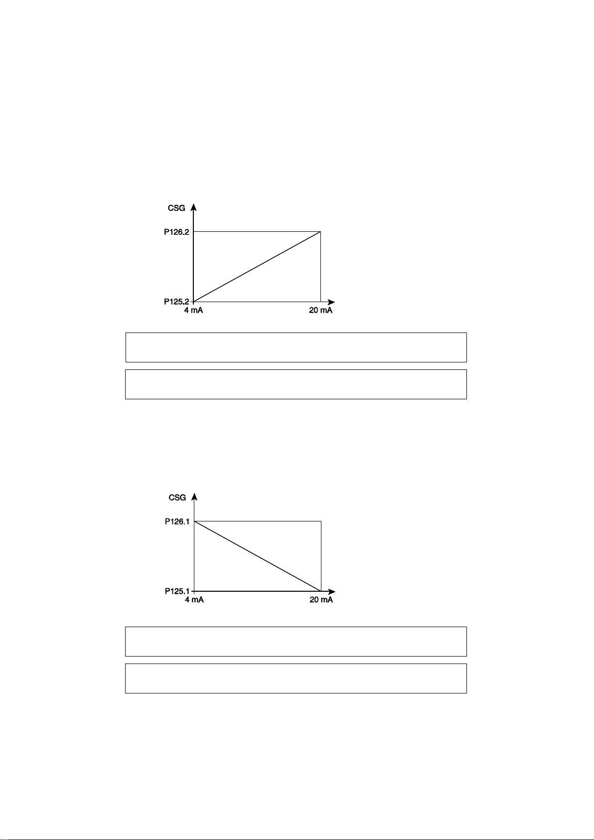
9.10 Setpoint selection via on/off input
P 1 2 5 . 2 S T P F O R 4 m A
H E A T I N G - X x . x °
P 1 2 6 . 2 S T P F O R 2 0 m A
H E A T I N G - x x . x °
P 1 2 5 . 1 S T P F O R 4 m A
C O O L I N G - x x . x °
P 1 2 6 . 1 S T P F O R 2 0 m A
C O O L I N G - x x . x °
4 -20 mA input
4 -20 mA input
If the number of setpoints = 2 with selection via on/off input (the on/off input corresponds to terminals 4-6 on terminal block J6 on the
motherboard).
In cooling mode:
- If the setpoint is not adjusted based on the outdoor temperature
or there is a fault on the outdoor temperature sensor, the control
setpoint = P121 if the on/off input is open or P122 if the on/off
input is closed.
In heating mode:
- If the setpoint is not adjusted based on the outdoor temperature
or there is a fault on the outdoor temperature sensor, the control
setpoint = P123 if the on/off input is open or P124 if the on/off
input is closed.
- If the setpoint is adjusted based on the outdoor temperature and
there are no faults on the outdoor sensor:
The setpoint is calculated using P121 if the on/off input is open. If
the input is closed, the setpoint is calculated using P122.
- If the setpoint is adjusted based on the outdoor temperature and
there are no faults on the outdoor sensor:
The setpoint is calculated using P123 if the on/off input is open. If
the input is closed, the setpoint is calculated using P124.
9.11 Variable setpoint via 4-20 mA input
In heating mode:
- Displayed if P120 = 3 and in HEATING mode:
If setpoint adjustment based on outdoor temperature = No or
there is an outdoor sensor fault → Control setpoint = result of
diagram 1
If the setpoint is adjusted based on the outdoor temperature =
Yes and there are no faults on the outdoor sensor:
The derived setpoint is calculated using the outdoor temperature.
In cooling mode:
Displayed if P120 = 3 and in cooling mode:
If setpoint adjustment based on outdoor temperature = No or there
is an outdoor sensor fault → Control setpoint = result of diagram 2
If setpoint adjustment based on outdoor temperature = Yes and
there are no faults on the outdoor sensor → The derived setpoint
is calculated using the outdoor temperature . The result of
IMPORTANT NOTE ABOUT THIS FUNCTION: operating problems may occur if parameters P127 and P131 are set to „Yes‟ and the
controller delivering the 4-20 mA signal has its own function for shifting the setpoint based on the outdoor temperature.
If the minimum value of the signal becomes less than 4 mA, the value of the setpoint will not drop below the minimum setpoint.
Diagram 1
The result of diagram 1 is taken as the setpoint (P123 or P124).
If P120 is set to „3‟, P131 automatically switches to „No‟.
- To reverse the direction of the slope, simply set P125.2 to >
P126.2 with a minimum difference of 5 K.
Diagram 2
diagram 2 is taken as the setpoint (P121 or P122).
If P120 is set to „3‟, P127 automatically switches to „No
- To reverse the direction of the slope, simply set P125.1 to >
P126.1 with a minimum difference of 5 K
56
Page 59
9.12 Operating mode selection
M A C H I N E O F F
O P E R A T I N G M O D E C H A N G E
E X C H . 1 W A T E R I N L E T
S E N S O R F A U L T J 7 / 2 - 3
E X C H . 1 W A T E R O U T L E T
S E N S O R F A U L T J 7 / 4 - 5
+ 5 V
R = 8.96 kΩ
50 kΩ sensor
+ 5 V
R = 15.4 kΩ
10 kΩ sensor
If P119 = 4 (cooling/heating via on/off input):
The unit is controlled, during water heating or water chilling, based on the mode selected via the input located:
- Between terminals 5-6 on terminal block J6 on the motherboard
if P2 = water-to-water
- Between terminals 1-2 on terminal block J4 on additional board
1 if P2 = reversible air-to-water, 1 circuit
- Between terminals 1-2 on terminal block J2 of additional board 2
(cycle reversal) if P2 = reversible air-to-water, 2 circuits
The contact must be closed in order to be able to select heating
A fault will occur if the operating mode is changed while the machine is running:
- Unit shut off,
- General fault LED on
Automatic acknowledgment:
- The operating mode changes if the change is confirmed via the
On/Off button or the automatic operation control.
If P2 = reversible air-to-water, the operating mode may be switched with the unit running. After the operating mode is changed, the unit will
stop and restart in its new operating mode and take into account the short-cycle protection.
mode, and it must be open in order to be able to select cooling
mode.
- If P2 = water-to-water, the machine must be shut off via the
On/Off button or the automatic operation control and winter
protection must be shut off before the operating mode may be
changed.
- LED of initial mode flashes; fault control contact closed (not
stored in fault memory)
- If the input returns to its original state, the unit resumes its initial
operating mode.
10 MANAGEMENT OF THE ANALOGUE INPUTS
10.1 Temperature sensor
Diagram of sensors: All sensor faults are taken into account in the fault memory.
Water inlet sensor: CTN 10 K at 25°C (if P2 = 1, 2 or 3)
This sensor monitors the water temperature on the exchanger inlet in order to:
- Adjust the unit (water return control).
- Monitor the operation of the unit if the water return temperature
is too high (load limiting).
- Sensor wire cut and short circuit:
In cooling mode:
- Unit shut off, message on LCD, unit fault LED lit steady, fault saved in fault memory, fault relay in On position.
In heating mode:
- Water-to-water unit → No effect on control, message on LCD,
unit fault LED flashes, fault saved in fault memory.
- Reversible air-to-water unit and water return control→ Unit shut
off, message on LCD, unit fault LED lit steady, fault saved in fault
memory, fault relay in On position.
Water outlet sensor on heat exchanger 1: CTN 10 K at 25°C (if P2 = 1, 2 or 3)
This sensor monitors the water temperature on the exchanger outlet in order to:
- Adjust the unit (to water supply) → (P6 = 1) and (P141 = 3 or 4)
and cooling mode or (P02 = 3), (P6 = 1) and (P141 = 3 or 4) and
heating mode
- Enable the frost protection
- Sensor wire cut and sensor short circuit → Fault relay in On position
If this sensor is used for control, the unit is shut off (message from
table 1 in machine status menu shown on LCD, unit fault LED lit
steady, fault saved in fault memory). If heating mode is on: the
electric auxiliary heaters are turned on if possible and the boiler
relay is in the On position if P111 = boiler).
- Display the chilled water or hot water inlet temperature (display
range: -40 to 99°C, resolution: 0.1 K).
- This fault is acknowledged automatically
- Reversible air-to-water unit and water return control → No effect
on control, message on LCD, unit fault LED flashes, fault saved in
fault memory.
- Display the water outlet temperature (display range: -40 to
99.9°C, resolution: 0.1 K).
- This fault is acknowledged automatically
If the sensor is not used for control (i.e. it is used only for the frost
limit), the fault is a circuit fault (message from circuit 1 table in
machine status menu shown on LCD, circuit fault LED lit steady,
fault saved in fault memory).
57
Page 60
Water outlet sensor on heat exchanger 2: CTN 10 K at 25°C (if P2 = 1, 2 or 3)(if P6 = 2 → two sensors + manifold sensors).
E X C H . 2 W A T E R O U T L E T
S E N S O R F A U L T A D D 2 J 4 / 1 - 2
O U T . T E M P . S E N S O R F A U L T
J 7 / 1 - 2
E X C H . x R E F R . F R O S T
P R O T . S E N S . F A U L T J x / x - x
C O I L x C I R C U I T x
S E N S O R F A U L T J x / x - x
C O N D E N S E R I N L E T S E N S O R
F A U L T J 7 / 5 - 6
This sensor monitors the water temperature on the exchanger outlet in order to:
- Enable the frost protection
- Display the water outlet temperature (display range: -40 to
- Sensor wire cut and sensor short circuit → Fault relay in On position
This sensor is not used for control (i.e. it is used only for frost
protection; control is provided by the manifold sensor). The fault is
Outdoor air sensor: CTN 10 K at 25°C
This sensor monitors the temperature of the outdoor air in order to:
- Adjust the system based on the outdoor temperature (cooling
and heating). If the sensor wire is cut (open circuit) or the sensor
short-circuits, the unit is adjusted to the setpoint value (heating
and cooling) and a fault is displayed.
- Limit the operation of the unit based on the minimum
- Sensor wire cut and short circuit:
. Control based on outdoor temperature inhibited; control using setpoint.
. If the unit is running in heating mode and can run with the
electric stages, the compressors are shut off, control is on the
electric stages, a message appears on the LCD, the unit fault
LED flashes, and the fault is saved in fault memory.
Frost protection sensor for refrigerant in heat exchanger (1 or 2): CTN 10 K at 25°C (if P2 =1, 2 or 3 unless P1 = R407C, P2 = 3 and P3 = 2).
This sensor monitors the temperature of the refrigerant at the heat exchanger inlet in order to:
- Protect the heat exchanger from frost:
. Power reduced if several control stages are used
. Slope of fans changed
. Unit shut off
- If the sensor wire is cut or the sensor short-circuits, the
corresponding circuit is shut off, a message appears on the LCD,
the circuit x fault LED is lit steady, the fault is saved in the fault
Coil sensor (A to D): CTN 10 K at 25°C
If P2 = reversible air-to-water, this sensor manages the freon temperature at the coil outlet in order to:
- Manage (turn on and off) a defrosting cycle
- Display the coil temperature (display range: -40 to 99.9°C,
If the sensor wire is cut or the sensor short-circuits:
In cooling mode:
Normal operation, message on LCD, circuit x fault LED flashes, fault saved in fault memory.
In heating mode:
- If outdoor temperature 10°C → normal operation, message on
LCD, circuit x fault LED flashes, fault saved in fault memory.
Condenser hot water sensor: CTN 10 K at 25°C (if P2 = 1 and P141 = 3 or 4) = P258 (if P2 = 1 and P141 = 1) = P257
This sensor monitors the water temperature at the condenser exchanger‟s inlet (or outlet) in order to:
- Adjust in heating mode
- Display the condenser‟s water temperature (display range: -40 to 99.9°C, resolution: 0.1 K)
This fault is acknowledged automatically
- Sensor wire cut and short circuit:
In cooling mode:
Normal control, message on LCD, unit fault LED flashes, fault saved in fault memory, general fault relay in On position.
In heating mode:
Unit shut off, message on LCD, unit fault LED flashes, fault saved in fault memory, general fault relay in On position, boiler relay in On position
if P111 = boiler.
99.9°C, resolution: 0.1 K).
- This fault is acknowledged automatically
a circuit fault (message on LCD, circuit fault LED lit steady, fault
saved in fault memory).
temperature in heating mode.
- Display the outdoor air temperature (display range: -40 to
99.9°C, resolution: 0.1 K).
- This fault is acknowledged automatically
. If P2 = water-to-water, the unit continues to operate and the fault
is reported (message from table 2 in machine status menu shown
on LCD, unit fault LED flashes, fault saved in fault memory)
. In all other cases: unit shut off, message on LCD (table 1 in machine
status menu), unit fault LED lit steady, fault saved in fault memory,
heat trace cabled turned on, fault relay in On position, boiler relay in
On position if heating mode on and P111 = boiler.
- Refrigerant frost protection temperature displayed (display
range: -40 to 99.9°C, resolution: 0.1 K)
- This fault is acknowledged automatically
memory, the general fault relay is in the On position, and the
auxiliary heaters are turned on if heating mode is on.
resolution 0.1 K).
- This fault is acknowledged automatically
- If outdoor temperature < 10°C → circuit x shut off, message on
LCD, circuit fault LED flashes, fault saved in fault memory.
58
Page 61
Heat exchanger ambient sensor: CTN 10 K at 25°C (if P2 = 2)
E X C H A N G E R A M B I E N T T E M P .
S E N S O R F A U L T J 7 / 5 - 6
D . T E M P . S E N S O R X F A U L T
J x / x - x
M A N I F . W A T E R O U T L E T
S E N S O R F A U L T A D D 2 J 4 / 2 - 3
S U C T I O N T E M P . S E N S O R
F A U L T C I R C U I . x J x / x x - xx
L I Q U I D T E M P . S E N S O R
F A U L T C I R C . x J x / x x - x x
This sensor monitors the temperature inside the hydraulic enclosure housing the heat exchanger(s) in order to:
- Turn on the heaters
- Display the temperature inside the enclosure (display range: -40
- Sensor wire cut and short circuit: heaters turned on (relay in On
position), message on LCD, unit fault LED flashes, fault saved in
Control stage discharge sensor (1, 2, 3 or 4): CTN 50 K at 25°C (all configurations)
- Monitors the discharge temperature on the compressors
- Displays the discharge temperature (display range: 5 to 150°C, resolution 1 K).
- If the sensor wire is cut (check 5 minutes after compressor
turned on) and the sensor short-circuits (continuous monitoring),
the corresponding control stage is turned off and the auxiliary
heaters are turned on if need be. If there are no auxiliary heaters,
the boiler relay moves to the On position if P111 = boiler.
Water manifold outlet sensor: CTN 10 K at 25°C (if P2 = 1, 2 or 3 and P6 = 2)
This sensor monitors the water temperature on the exchanger outlet in order to:
- Adjust the unit (to water return)
- Display the common water outlet temperature
- Sensor wire cut and short circuit:
. If water return control or if P2 = water-to-water and heating mode
on (i.e. sensor not used for control):
Normal control, message from table 2 in machine status menu
shown on LCD, unit fault LED flashes, fault saved in fault
Circuit suction sensor: CTN 10 K at 25°C (all configurations)
If P42 = 2 (electronic expansion valve on CIAT board)
The sensor is connected to the expansion valve board and the temperature information is transmitted over the bus link.
The sensor monitors the suction temperature in order to:
- Display the superheat temperature (display range: -40 to 99.9°C,
resolution: 0.1 K)
- This fault is acknowledged automatically
- If the sensor wire is cut or the sensor short-circuits:
. If P43 = No: a secondary fault is displayed, the fault LED
flashes; the circuit fault relay is in the On position and the fault is
automatically acknowledged
Fault message:
Circuit liquid sensor: CTN 10 K at 25°C (all configurations)
This sensor measures the liquid temperature in order to:
- Display the subcooling temperature (display range: -40 to
99.9°C, resolution: 0.1 K).
- This fault is acknowledged automatically
Fault message:
Fault detection values:
- For the 50 K sensors: Cut-off fault (or sensor absent) if < 5°C
and unit operating for
5 minutes, and sensor short-circuit if > 148°C.
to 99.9°C, resolution: 0.1 K)
- This fault is acknowledged automatically
fault memory + general fault relay in On position.
A message appears on the LCD, the circuit fault LED is lit steady,
and the fault is saved in the fault memory.
- This fault must be acknowledged manually if the temperature <
145°C. The discharge fault must also be acknowledged.
(display range: -40 to 99.9°C, resolution: 0.1 K).
- This fault is acknowledged automatically
memory, general fault relay.
. If water outlet control and (cooling mode on or P2 = 3):
Unit shut off, message from table 1 in machine status menu
shown on LCD, unit fault LED lit steady, fault saved in fault
memory, general fault relay
. If P43 = Yes: The corresponding circuit is turned off and the
auxiliary heaters are turned on if need be. If there are no auxiliary
heaters, the boiler relay moves to the On position.
If P111 = Boiler. A message appears on the LCD, the circuit fault
LED is lit steady, and the fault is saved in the fault memory and
automatically acknowledged.
- If the sensor wire is cut or the sensor short-circuits, a secondary
fault is displayed, the fault LED flashes, the circuit fault relay is in
the On position, and the fault is automatically acknowledged
- For the 10 K sensors: Cut-off fault (or sensor absent) if < -40°C
and sensor short-circuit if > 99°C.
59
Page 62
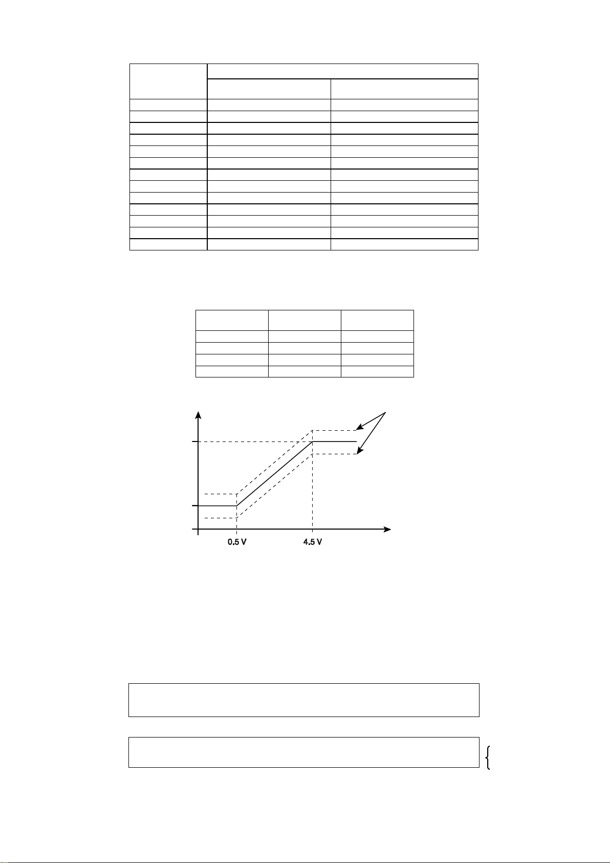
Correspondence table:
Temperature
(°C)
SENSOR RESISTANCE Ω
DISCHARGE SENSOR
50 KΩ
CONTROL AND OUTDOOR
SENSOR 10 KΩ
10 - 55340
-5 - 42340
0
162250
32660
5
126977
25400
10
99517
19900
15
78570
15710
20
62468
12490
25
50000
10000
30
40280
8058
35
32650
6532
40
26624
5326
45
21834
4368
50
18005
3602
Low value
from
High value
to
P31
P30
HP1
P33
P32
HP2
P37
P36
LP1
P39
P38
LP2
P 3 x x H P x P R E S S U R E ↑
x x . x b ↓
S E N S O R A D J U S T M E N T H P x
x x . x b 0 . 0 b
[- 1 + 1] 0 by default
High value
Low value
Pressure
Voltage
Calculation
with
adjustment
10.2 Pressure sensor
The high and low values for the HP/LP pressure sensors are given below:
The sensors are adjusted using parameters P30 to P39.
Measurement range:
- Power supply: 5 V DC
- Signal: 0.5 - 4.5 V
Short-circuit faults will be detected by a voltage ≥ 4.75 V.
Open-circuit faults will be detected by a voltage ≤ 0.25 V.
The HP sensor will:
- Monitor the HP pressure in the circuit and relay this information
- Control the unit using the HP
The LP sensor will:
- Monitor the LP pressure in the circuit and relay this information - Monitor for refrigerant leaks before turning on stages
When reading the operation parameters for the pressure levels, the sensors can be adjusted with the OK button if is a difference is
found between a value that is read and the corresponding value measured by a pressure gauge.
Example:
Press OK to access and change the adjustment value.
Press OK to confirm the new adjustment value and go back to the
operation parameter.
Press ESC to cancel any changes made and go back to the
operation parameter.
The pressure values given are for relative pressure.
- Control the condensing pressure
This readjustment will be used to correct the difference between the value
measured by a pressure sensor and the value read on a pressure gauge.
The resulting new slope will then be used for control.
60
Page 63
11 MANAGEMENT OF THE WATER PUMPS
P U M P x O N
x x s
P 2 7 P U M P C O N T R O L L E D
B Y B O I L E R Y E S
P 2 7 P U M P C O N T R O L L E D
B Y B O I L E R N O
11.1 Pump 1
Pump 1 is assigned to the main hydraulic network. Therefore, it is used in all configurations:
- If P2 = air-to-water or reversible air-to-water and P25 = 2, it will
be managed alternately with Pump 2.
The pump that has run for the shortest amount of time starts up first.
11.2 Pump 2
Pump 2 is used only in certain configurations:
A) If P2 = water-to-water, pump 2 is assigned to the customer‟s
secondary network and its control mode is determined by P108.
- If P108 = depending on control mode, the pump control is linked
to the unit control:
Automatic time delay countdown.
This time delay is maintained during test mode.
- If P108 = depending on On/Off, the pump control is linked to the
operation of the unit.:
. The pump is turned on (via On/Off and with the automatic
operation control input closed; or via On/Off, with the automatic
B) If P2 = air-to-water or reversible air-to-water, it depends on P25
- If P25 = 0 or 1 (only one pump supplied.) there is no pump 2.
- If P25 = 2, the unit is supplied with a backup pump. This pump is
managed by On/Off control and runs alternately with pump 1. The
pump that has run for the shortest amount of time starts up first.
- Otherwise, the pumps may be turned on using the On/Off button
(and automatic operation control input closed).
The pump is shut off 1 minute after the last control stage turns off.
Pump x is turned on before the first control stage (where x is the
value entered in P109).
The pump is shut off 1 minute after the last control stage turns off.
operation control input closed and winter protection activated by
outdoor temperature; or remotely via a PC, modem or other).
The pump is immediately turned off when P108 is changed and
switches from On/Off control to Depending on control mode
(unless control mode called for).
The pump is shut off 1 minute after the last control stage turns off.
The next time the machine is turned off by the control after 7 days
of operation with the same pump, the pumps are switched (by
turning off the one that was running) in order to balance the
runtimes.
The pump is shut off 1 minute after the last control stage turns off.
11.3 Pump management if P2 = 3 (reversible air-to-water) + heating mode + P111 = Boiler
Parameter P27 is used to have the pump controlled by the operation of the boiler.
A) If P27 = Yes: When the boiler is turned on, the pump is shut off
unless there is a risk of the unit freezing (outdoor temperature ≤
P52 and P261 ≤ 30°C).
The boiler will continue to operate if the heat pump malfunctions.
B) If P27 = No: The pump is controlled by the On/Off button. It continues to run even when the boiler is authorised to operate.
A tank with four nozzles must be installed on the system and
the boiler must have its own pump and its own control with its own
protections
11.4 Unseizing and switching the pumps
If any of the pumps remains off (for a reason other than a fault) for over 7 days, it must be turned on between 9.00 am and 9.00 pm and be
allowed to run for 2 minutes.
- If P25 = 2, the pump with the longest runtime is turned off
after being unseized.
- If the unit is turned off via the On/Off button or the automatic
operation control and a water flow fault occurs during
unseizing, both pumps are turned off.
12 WINTER PROTECTION
12.1 Frost protection of pumps and heat exchangers while unit is off
This function protects the pump(s) and the heat exchanger(s) from freezing.
The heater and heat trace cable outputs are enabled only when P2 = air-to-water and reversible air-to-water.
P265 becomes visible if P2 = air-to-water and reversible air-to-water
12.1.1 Use with pure water: If P52 ≥ its standard adjustment value based on the refrigerant type:
1) Heater control:
- If exchanger ambient temperature ≤ P220 or ambient temp.
sensor fault and water inlet temperature≤ (P52 + 2) + all
compressors off + pump off if P25 ≠ 0 → Heaters on.
- If ambient temperature sensor fault and water inlet temperature ≤
(P52 + 2) + all compressors off + pump off if P25 ≠ 0 → Heaters on.
- If exchanger ambient temperature > P220 + P222 or water inlet
temperature ≥ (P52 + 2) + P222 or if a compressor or a pump is
on if P25 ≠ 0 → Heaters off.
2) Heat trace cable control:
- If outdoor temperature sensor ≤ P220 and water inlet
temperature ≤ 20°C + all compressors off + pump off
if P25 ≠ 0 → Heat trace cables on
- If outdoor temperature sensor fault and water inlet temperature ≤
20°C + all compressors off + pump off
if P25 ≠ 0 → Heat trace cables on
- If outdoor temperature > P220 + P222 or water inlet temperature
≥ 20°C + P222 or if a compressor or a pump is on → Heat trace
cables off.
61
Page 64
12.1.2 Use with glycol/water mix: If P52 < its standard adjustment value based on the refrigerant type:
P 4 3 5 H E A T T R A C E
C A B L E O U T P U T O N
P 4 3 6 H E A T E R
O U T P U T O N
P 2 9 . 1 H E A T R E C O V . E X C H .
F R O S T P R O T E C T I O N Y E S
P 4 3 7 R E C O V E R Y F R O S T
P R O T . O U T P U T O N
S H O R T - C Y C L E P R O T E C T I O N
S T A G E x C I R x x x m n x x s
S T A G E x C I R C U I T x A T
M I N . S T O P x x m n x x s
1) Heater control:
- If exchanger ambient temperature and water inlet temperature ≤
P52 + 2 K + all compressors off + pump off if P25 ≠ 0 → Heaters on.
- If exchanger ambient temp. sensor fault and water inlet
temperature ≤ P52 + 2 K + all compressors off + pump off
if P25 ≠ 0 → Heaters on.
- If exchanger ambient temperature P265 or water inlet
temperature > P52 + 2 + P222 or if a compressor or a pump is on
if P25 ≠ 0 → Heaters off.
Output state displays:
12.1.3 Controlling frost protection for partial recovery (desuperheater) or total recovery option:
Parameter visible only if P2 (unit type) = air-to-water or reversible air-to-water:
Default value:
- No if P29 (total recovery) = No
- Yes if P29 = Yes
- If P29.1 = Yes and outdoor temperature ≤ P220: heat trace cables on
- If P29.1 = Yes and outdoor temperature sensor fault: heat trace cables on
- If P29.1 = Yes and outdoor temperature > P220 + P222: heat trace cables off.
The heat trace cables will be controlled by output 4 on terminal block J5 on additional board 1 (1-circuit cycle reversal). If P29.1 is set to „Yes‟
and the link with ADDitional board 1 is missing, a link fault should appear.
Output state display:
2) Heat trace cable control:
- If outdoor temperature ≤ 0 and water inlet temperature ≤ 0°C +
all compressors off + pump off if P25 ≠ 0 → Heaters on.
- If outdoor temperature sensor fault and water inlet temperature ≤
0°C + all compressors off + pump off if P25 ≠ 0 → Heaters on.
- If outdoor temperature > 0 + P222 or water inlet temperature
≥ 0°C + P222 or if a compressor or a pump is on if P25 ≠ 0 →
Heat trace cables off.
12.2 Water loop winter protection
In heating mode:
This function is possible only if P142 = Yes, the automatic
operation control input is open and the On/Off button on the
console is set to „On‟.
In this case the function must maintain water inlet temperature on
In cooling mode:
This function is possible only if P142 = Yes, the automatic
operation control input is open and the On/Off button on the
console is set to „On‟. In this case the pump is turned on if the
the heat exchanger at 30°C as soon as the outdoor temperature
falls below 3°C (2 K differential).
The return temperature will be maintained at 30°C if the outdoor
temperature sensor ever malfunctions.
outdoor temperature falls below P220 and shut off at P220 + P222.
The pump will be forced on if the outdoor temperature sensor
ever malfunctions.
13 MANAGEMENT OF THE FUNCTIONS
13.1 Management of the compressor protections
13.1.1 Short-cycle protection:
Information from compressor manufacturer:
Compressors are not allowed to start more than 12 times an hour
(on/off time of 5 minutes and minimum of 3 minutes between starts).
The on time + off time will be adjustable via parameter P50.
In test mode, the short-cycle protection is shunted. The compressor can start up immediately at the end of the pump start-up time delay.
The information is displayed only if a call is made to turn on the stage while the time delay is counting down.
The auxiliary heaters do not operate during short-cycle protection.
On power-up, the SCP = 0 minutes and the minimum off time =
3 minutes.
62
Page 65

13.1.2 Forced stop of compressors
This function prevents the compressor stages from operating individually.
It is enabled and disabled via the following parameters:
P230: On authorisation, stage 1 circuit 1
P231: On authorisation, stage 2 circuit 1
P232: On authorisation, stage 1 circuit 2
P233: On authorisation, stage 2 circuit 2
13.2 Management of the time counters
The number of hours of operation in each mode (cooling and heating) can be viewed for each pump and each compressor stage.
The parameters are as follows:
P285: Heating mode runtime (in hours)
P286: Cooling mode runtime (in hours)
P287: Pump 1 runtime
P288: Pump 2 runtime
P311: Stage 1, circuit 1 runtime
P314: Stage 2, circuit 1 runtime
In heating mode (P285):
The time delay increments if heating mode is on via the On/Off button and the automatic operation control input is closed or the winter
protection is on with a control stage on.
In defrost mode (P285)::
These counters are visible if P285 is opened, Enter is pressed on the console and P159 = optimised.
The top line corresponds to the total runtime in heating mode (excluding defrosting). The second line corresponds to the total defrosting time.
These counters have been added in order to know the gain compared to frosting during a fixed period of time.
In cooling mode (P286):
The time delay increments if cooling mode is on via the On/Off button and the automatic operation control input is closed or the winter
protection is on with a control stage on.
P341: Stage 1, circuit 2 runtime
P344: Stage 2, circuit 2 runtime
There are also monitoring counters: P289, P290, P308, P309,
P310, P313, P322, P323, P324, P338, P339, P340, P343, P352,
P353, and P354.
13.3 Management of compressor start-up
Applies only for units with several compressors and if the number of stages on circuit 1 1 and the number of stages on circuit 2 1.
Parameter P13 is visible only:
- if P3 (No. of circuits) = 1 and P4 (No. of stages on circuit 1) = 2
- if P3 (No. of circuits) = 2 and P4 (No. of stages on circuit 1) = 2 and P5 (No. of stages on circuit 2) = 2
13.3.1 With balanced tandem compressors:
Before stages are turned on, the runtime of each stage is always checked so that the stage that has run the least is started first.
When only one of the two compressors on each circuit is running, it is turned off after 4 hours and the other compressor is turned on.
With 1 circuit and 1 stage: No runtime balancing.
With 1 circuit and 2 stages: The two stages on the circuit are balanced (during operation and at start-up).
With 2 circuits and 3 stages: On circuit X, the first of the three stages to be turned on is the one that has run the least amount of time. On circuit
Y, the second stage to be turned on (circuit change) is the one that has run for the second-shortest time. Then the third and last stage is started.
With 2 circuits and 4 stages: On circuit X, the first of the four stages to be turned on is the one that has run the least amount of time. On
circuit Y, the second stage to be turned on (circuit change) is the one that has run for the second-shortest time. The third stage to be turned on
is the stage that has run for the third-shortest time. Then the fourth and last stage is turned on.
This function must take into account:
- The stage restriction
- The short-cycle protection
The compressors are turned off in sequence, starting with the compressor that has run the longest.
13.3.2 With unbalanced tandem compressors and partial-load control:
Partial-load control is enabled on water chillers equipped with scroll compressors with one or two refrigerating circuits with two or four control
stages.
It makes it possible to manage up to six control stages using four compressor outputs on CONNECT 2.
On machines equipped with unbalanced tandem compressors, this type of control is particularly useful in obtaining the following breakdown:
If P3 (number of circuits) = 1 → 33%, 66%, 100% If P3 = 2 → 16%, 33%, 50%, 66%, 83%, 100%
The stages must therefore be assigned on the compressor outputs on CONNECT 2
Motherboard
- Terminal 2 on terminal block J3, output of stage 1 on circuit 1 =
most powerful stage on circuit 1
Additional board 2, circuit 2 function
- Terminal 2 on terminal block J3, output of stage 1 on circuit 2 =
most powerful stage on circuit 2
With 1 circuit and 1 stage: No partial-load operation
With 2 circuits and 3 stages: No partial-load operation as the compressors are of the same size (LGN and LJA range). The compressor
that has run the least is turned on first.
This function must take into account:
- The stage restriction,
- The short-cycle protection,
Compressor switching management:
When only one of the two compressors on each circuit is running, it is turned off after 4 hours and the other compressor is turned on.
- The authorisation for the stages to turn on
- Compressor faults
- Terminal 3 on terminal block J3, output of stage 2 on circuit 1 =
most powerful stage on circuit 1
- Terminal 3 on terminal block J3, output of stage 2 on circuit 2 =
most powerful stage on circuit 2
- The authorisation for the stages to turn on
- Compressor faults
63
Page 66

Short-cycle protection management (SCP):
M A C H I N E O F F
F A U L T S O R L I M I T E R
C I R C . x W A T E R F R O S T L I M
P O W E R R E D U C .
C I R C . x R E F R I G F R O S T L I M
P O W E R R E D U C .
- Call for power:
If the only available stage is in SCP mode, the machine remains in its current state and SCP is indicated by the flashing LED on the console.
Before a stage is turned on, the runtime of each stage is always checked so that the stage that has run the least is started first.
13.4 Management of the reversing valves
The reversing valves are fitted on reversible units only.
They are managed by the following convention:
- In cooling mode: the reversing valves are supplied.
- In heating mode: the reversing valve are not supplied.
The supply to the reversing valves is cut off 30 minutes after the last stage on the corresponding circuit is turned off. This time delay becomes
30 seconds in test mode.
13.5 Management of configurable output P111:
The output between terminals 9-10 on terminal block J3 on the motherboard is configurable so that the customer can define its function.
Max. power: The NC contact informs the customer that the unit is running at full power (all compressors and all electric stages).
Boiler: The NC contact allows the customer to activate an auxiliary heater. This type of operating mode is described in section 21
“Management of the back-up boiler”.
Cooling/Heating: The NC contact informs the customer of the heating operation of the unit. The NO contact informs the customer of the
cooling operation of the unit.
Backup on all faults (on air-to-water machines only):
The NC contact informs the customer that the machine is either not operating at full capacity (a compressor is off) or has been shut off
following the detection of a fault. The machine will remain off until the fault is acknowledged with the Reset button.
Display:
Machine fault output on
- General fault LED on console lit steady
To see which type fault caused the machine to be shut off, go to the fault memory.
List of faults and impairments that shut off the machine if P111 is set to 'backup on all faults':
- Pump fault
- Intermediate and final water flow fault
- Limiter on water outlet
- Intermediate and final water frost fault
- Limiter on refrigerant
- Intermediate and final frost fault on refrigerant
- Exchanger frosting fault
- Limiter on high pressure
- Intermediate and final high pressure control fault
- Manual high pressure fault
- Motor fault
- Limiter on discharge
- Intermediate and final discharge fault
- Intermediate and final low pressure fault
- Water inlet sensor fault
- Exchanger 1 or 2 water sensor fault
- Refrigerant sensor fault
- Discharge sensor fault
- Manifold water outlet sensor fault if control on outlet
- Sensor fault
- Excessively low outdoor temperature fault
- Electronic expansion valve fault
- Fan fault if P3 and P180 = 1
- Maximum superheat fault
- Minimum superheat fault
- Limiter on max. air during cooling
- Phase controller fault
- Suction sensor fault if P43 = Yes
- Excessively high outdoor temperature fault
14 SELF-ADJUSTING FUNCTIONS
These functions allow the machine to adjust itself to certain occasionally extreme operating conditions and thus avoid stops caused by faults.
14.1 Self-adjusting function: water frost limit
Operation:
- Before shutting down after a fault occurs, the unit reduces its power by turning off a stage (if there are two on the circuit), or by reducing the
compressor to half speed. In the case of INVERTER units, they shut off if they are already running at half speed.
- The threshold is detected by the water outlet sensor at P52 + 0.8 K.
- The unit returns to normal operation at P52 + 2 K for 5 minutes and then the HP gradually rises to its set threshold (P181).
- This function operates on each circuit.
Display:
14.2 Self-adjusting function: refrigerant frost limit
Operation:
Before shutting down after a fault occurs, the unit reduces its power by turning off a stage (if there are two on the circuit), or by reducing the
compressor to half speed. In the case of INVERTER units, they shut off if they are already running at half speed. It raises the high pressure
level by decreasing the speed of the fans (units with air-cooled condensers only).
The threshold is detected by the sensor placed on the freon pipe at the evaporator inlet at P52 - P53 + 2 K for 10 seconds. The unit returns to
normal operation at P52 - P53 + 3.5 K and then the HP gradually rises to its set threshold (P181).
Display:
64
Page 67
Exception: P08 = "SWEP DOUBLE":
C X E V A P T . / F R E E Z E L I M . X
U N I T I N P A R T L O A D
C I R C U I T x H P L I M I T
P W R R E D U C T I O N x x m n
C I R C . X D . T E M P L I M I T
P W R R E D U C T I O N x x m n
C I R C . x M I N . H P L I M .
P O W E R R E D U C .
W A T E R R E T U R N T . L I M I T
U N I T P W R R E D U C T I O N
C I R C X H 2 O F R O S T F A U L T
x C U T ( S ) I N 2 4 H
The limit is detected by the saturation temperature (LP side), at P52 – P53 for 60 seconds. Normal operation resumes when the saturation
temperature (LP side) rises to a sufficient level.
Display:
14.3 Self-adjusting function: HP pressure limit
Operation:
- Before shutting down after a fault occurs, the unit reduces its power by turning off a stage, or by slowing the compressor to 50 Hz, or by
shutting off Inverter units for 30 minutes.
- The threshold is detected by the HP sensor at P54-P195 and returned to normal operation after 30 minutes.
- This time period becomes 30 seconds in test mode.
This function is turned on on both circuits at the same time.
Display:
Special case of Inverter machines in water heating mode: If the HP pressure ≥ P54 - P195, the CONNECT2 controller adjusts the control
setpoint so as not to push the compressors near their limits too often. If necessary, a coil defrosting cycle will be forced on.
14.4 Self-adjusting function: discharge protection, circuit 1 or 2
Operation:
- Before shutting down after a circuit fault occurs, the unit reduces its power for 30 minutes by turning off a stage.
- The threshold is detected by the discharge sensor at value P51 and the stage that was turned off is returned to normal operation after 30 minutes.
- This time period becomes 30 seconds in test mode.
Display:
Special case for reversible machines in water heating mode: If the discharge circuit temperature ≥ P151, the CONNECT controller adjusts
the control setpoint so as not to push the compressors near their limits too often.
If necessary, a coil defrosting cycle will be forced on.
14.5 Self-adjusting function: minimum HP, circuit 1 or 2
Operation:
- If the pressure measured by the HP sensor is ≤ P63 for water-to-water units, the controller lowers the circuit‟s power to avoid an excessive
drop in LP. Normal operation is restored at P63 + 1b.
Display:
14.6 Self-adjusting function for high water return temperatures
Operation:
- The water return temperature may be high as the installation warms up in cooling mode. This causes all the compressor stages to turn on
one after the other and can result in HP cuts and unwanted voltage spikes.
- To prevent this, the controller limits the turning-on of the stages if the water inlet temperature on the heat exchanger is higher than P171 as
long as the temperature does not drop below P171-5K.
Display:
15 FAULT FUNCTIONS
15.1 Water frost limit fault on circuits 1 and 2
Operation:
- Should the self-adjusting function be insufficient, a fault will occur on the unit when the temperature measured on the heat exchanger water
outlet is at P52 (measured for 15 seconds, or P52 – 1 K).
If this fault causes fewer than 3 shutdowns in 24 hours:
- Corresponding circuit shut off.
- Circuit fault output off
Display:
- Frost protection fault relay on optional board in Off position
- Circuit fault LED on console flashes
65
Page 68
If this fault causes more than 3 shutdowns in 24 hours:
C I R C U I T X O F F
W A T E R F R O S T F A U L T
x . W A T E R x F R O S T P R O T .
C I R C U I T X O F F
E XCH. A N T I FRE Z E F A U L T
C I R C X R E F F R O S T F A U L T
x C U T ( S ) I N 2 4 H
C I R C X R E F F R O S T F A U L T
x C U T ( S ) I N 2 4 H
C I R C U I T X O F F
R E F R I G . F R O S T F A U L T
x . R E F R I G . x F R O S T P R O T
- Corresponding circuit shut off.
- Fault output on
- Frost protection fault relay on optional board in On position
Display:
Saved in fault memory:
Resetting:
- If the number of faults in 24 hours ≤ 3 → the fault is automatically acknowledged if the temperature rises back above P52 + 6 K.
- If the number of faults in 24 hours > 3 → the fault is acknowledged if the temperature rises back above P52 + 6 K and Reset is pressed on the console.
- Circuit fault LED on console lit steady
- Boiler on if P111 = Boiler and heating mode.
- Auxiliary heaters on if P22 = Yes and heating mode.
15.2 Refrigerant frost limit fault on circuits 1 and 2
Frost on the heat exchangers is detected in two ways on most CIAT machines.
- Detection method 1: sensors monitor for deviations in low pressure and in the water outlet temperature. Such deviations indicate that ice has
started to form on the heat exchanger. There is no self-adjusting function; the risk of freezing is immediately handled as a fault. This method of
detection is standard on all CIAT units.
Parameters P58 and P59 are used in this mode of detection. Therefore, the lower their values, the more the frost protection is sensitive.
Display:
This function can be turned off via parameter P115 in order to perform maintenance.
- Detection method 2: frost is detected by a freon sensor on the heat exchanger inlet:
Operation:
- Should the self-adjusting function be insufficient, a fault will occur on the unit when the temperature measured on the freon pipe at the heat
exchanger inlet is at P52 - P53 (measured for 60 seconds).
If this fault causes fewer than 3 shutdowns in 24 hours
- Corresponding circuit shut off.
- Circuit fault output off
- Frost protection fault relay on optional board in Off position
Display:
If this fault causes more than 3 shutdowns in 24 hours:
- Corresponding circuit shut off.
- Fault output on
- Frost protection fault relay on optional board in On position
Display:
Saved in fault memory:
Resetting:
- If the number of faults in 24 hours ≤ 3 → the fault is automatically acknowledged if the temperature rises back above P52 - P53 +10 K.
- If the number of faults in 24 hours > 3 → the fault is acknowledged if the temperature rises back above P52 - P53 +10 K and Reset is pressed on the console.
- Circuit fault LED on console flashes
- Circuit fault LED on console lit steady
- Boiler on if P111 = Boiler and heating mode.
- Auxiliary heaters if P22 = Yes + heating mode
15.3 HP pressure fault, circuits 1 and 2
Operation:
- Information is sent by the pressure sensors on each circuit. This function prevents manual HP cuts during brief increases in HP during
momentary blockages in the condenser.
- Should the self-adjusting function be insufficient, a fault will occur on the circuit when the pressure measured is at P54.
If this fault causes fewer than 5 shutdowns in 24 hours:
- Corresponding circuit shut off.
- 30 min. time delay (in seconds in test mode).
- Fault output off
- Circuit x HP fault relay on optional board in Off position
- Circuit fault LED on console flashes.
- The number of faults over a 24 hour period is managed (P308
for circuit 1 and P338 for circuit 2).
66
Page 69
Display:
C I R x H P F A U L T x x m n
X C U T ( S ) I N 2 4 H
C I R C U I T X O F F
H P F A U L T
x . C I R C U I T x H P
D . T E M P F A U L T C x x x m n
x C U T ( S ) I N 2 4 H
C I R C U I T X O F F
D I S C H A R G E F A U L T
x - D I S C H . T . C I R C U I T x
C I R C U I T x L P F A U L T
x C U T ( S ) I N 2 4 H
C I R C U I T X O F F
L P F A U L T
If this fault causes more than 5
shutdowns in 24 hours:
- Corresponding circuit shut off.
- Fault output off.
Display:
Saved in fault memory:
Resetting:
- If the number of faults in 24 hours ≤ 5 → the fault is acknowledged after 30 minutes.
- If the number of faults in 24 hours > 5 → the fault is acknowledged if Reset is pressed on the console
- Circuit x HP fault relay on optional board in On position.
- Circuit LED on console lit steady.
15.4 Discharge temperature fault, circuit 1 or 2
Operation:
- Information is sent by the sensors placed on the discharge pipes (one per control stage).
- The maximum discharge temperature limit is set by parameter P51 + 1 K.
If this fault causes fewer than 5 shutdowns in 24 hours:
- Corresponding circuit shut off.
- 30 min. time delay (in seconds in test mode)
- Fault output off
Display:
If this fault causes more than 5
shutdowns in 24 hours:
- Corresponding circuit shut off.
- Fault output on
- Circuit x discharge temperature fault relay on optional board
Display:
Saved in fault memory:
Resetting:
- If the number of faults in 24 hours ≤ 5 → the fault is acknowledged after 30 minutes.
- If the number of faults in 24 hours > 5 → the fault is acknowledged if DISCH.T. ≤ P51 – 15°C and Reset is pressed on the console.
- Circuit x discharge temperature fault relay on optional board in
Off position
- Circuit fault LED on console flashes.
in On position
- Circuit fault LED on console lit steady
15.5 LP fault on circuit 1 or 2
Operation:
- If the pressure measured by the LP pressure sensor is ≤ P55, the controller records an LP fault.
- This input is checked 2 minutes after the first stage on the circuit is turned on. It is also checked when power is shut off but ignored both
during and 2 minutes after defrosting.
- Both of these time delays are maintained in test mode.
If this fault causes fewer than 3 shutdowns in 24 hours:
- Corresponding circuit shut off.
- Fault output off
Display:
If this fault causes more than 3 shutdowns in 24 hours:
- Corresponding circuit shut off.
- Fault output on
Display:
- Circuit x LP fault relay on optional board in Off position
- Circuit fault LED on console flashes
- Circuit x LP fault relay on optional board in On position
- Circuit fault LED on console lit steady
67
Page 70
Saved in fault memory:
x . C I R C U I T x L P
M I N S U P E R H E A T F A U L T C X
X C U T ( S ) I N 1 H
C I R C U I T X O F F
M I N . S U P E R H E A T F A U L T
M A X S U P E R H E A T F A U L T C X
X C U T ( S ) I N 1 H
C I R C U I T X O F F
M A X . S U P E R H E A T F A U L T
C X M I N . OVE R H E A T
C X M A X . OVE R H E A T
Resetting:
- If the number of faults in 24 hours ≤ 3 → the fault is automatically acknowledged if BP > P55 + 2b.
- If the number of faults in 24 hours > 3 → the fault is acknowledged if BP > P55 + 2b and Reset is pressed on the console.
If a fault occurs on the sensor on the open circuit, the fault is preceded in the fault memory by an LP fault.
Special case for reversible machines and water chilling: the fault threshold switches to P55+1 b and normal operation is restored if BP >
P55 + 3 b.
Special case for reversible machines and water heating:
Defrosting is forced on when the LP is < P55 for 1 minute.
If defrosting is forced on 3 times in 1 hour, the circuit with a LP fault is turned off the fourth time the LP drops below P55.
15.6 Management of superheat faults
The superheat temperature on the suction end of each circuit can be monitored by comparing the LP saturation temperature to the suction
temperature.
This protection is enabled by setting P43 to „Yes‟ (No by default). It protects the compressor(s) from excessively low or high superheat values.
If superheat protection = Yes → This function is turned on when at least the first control stage (per circuit) is on and 5 minutes after the first
stage is turned on.
Minimum superheat fault:
- If the superheat value (P307 or P337) drops below the minimum superheat limit value (P44) for 1 minute, the circuit is shut off and the
minimum superheat error message is displayed.
- The unit automatically restarts after 5 minutes (5 seconds in test mode).
- This function remains on in test mode.
Display:
If there are more than 3 cuts in 1 hour
The unit is turned off by the superheat protection. The Reset button must be pressed in order to restart the circuit.
Display:
Maximum superheat fault:
- If the superheat value (P307 or P337) rises above the maximum superheat limit value (P45) for 1 minute and the evaporating temperature <
15°C, the circuit is shut off and the maximum superheat error message is displayed.
- This function is turned off during defrosting.
- The unit automatically restarts after 5 minutes (5 seconds in test mode).
- This function remains on in test mode.
Display:
If there are more than 3 cuts in 1 hour, the unit is turned off by the maximum superheat protection and the Reset button must be pressed in
order to restart the circuit.
Display:
If a permanent fault occurs:
- Fault stored in memory in case of a mains power failure
- Fault saved in fault memory
If a temporary fault occurs:
- Fault not stored in memory if a mains power failure occurs
- Fault saved in fault memory
- The minimum or maximum superheat fault relay on the
Messages in the fault memory:
- Relay in On position
relay board is in the Off position
During test mode, the time delays are counted down in seconds,
not minutes.
68
Page 71
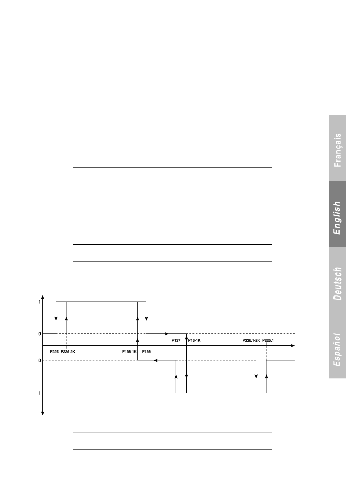
16 CONTROLS
M A C H I N E O F F
O P E R A T I N G M O D E C H A N G E
P 1 3 6 M A X A I R T E M P .
A U T O H E A T I N G M O D E – xx
P 1 3 7 M I N A I R T E M P .
A U T O C O O L I N G M O D E - xx
D E A D B A N D A U T O
H E A T I N G / C O O L I N G
Machine STATUS
HTG
MODE
CLG
MODE
Outdoor
temperature
Machine STATUS
16.1 Main control in cooling and heating modes
Definition and principle:
The chilled water and hot water temperatures are measured and compared with the setpoint value. Depending on the result, the compressor
stages are turned on or off. This check is performed on the heat exchanger‟s water outlet (water supply = PIDτ) or water inlet (water return).
16.1.1 Operating mode selection (P119):
- If P119 = 1 (Cooling)
Cooling only.
- If P119 = 2 (Heating)
Heating only
- If P119 = 3 (Cooling/Heating via console)
The operating mode can be changed only with the machine stopped
(automatic operation control input set to on, On/Off button).
The Heating/Cooling button will be disabled if it is pressed while the machine is running.
- If P119 = 4 (Cooling/Heating via on/off input)
The operating mode can be changed only with the machine stopped
(automatic operation control input set to on, On/Off button).
Attempting to change the operating mode while the machine is running will result in a fault:
. Machine stopped.
. Machine fault relay in On position.
Automatic reset:
- Either the machine changes its operating mode if the change is confirmed by pressing On/Off or if the automatic operation control input is
open;
- Or it resumes its initial operating mode if the input is restored to its initial value.
If P119 = 5, the machine switches between heating and cooling depending on the outdoor temperature:
- This function is visible only if P2 = reversible air-to-water
- When this function is turned on, the minimum heating limit and the maximum cooling limit (depending on the outdoor temperature) are reenabled and are set to the following values:
. For a minimum air temperature of -10°C if P7 ≠ INVERTER
-20°C if P7 = INVERTER
. For a maximum air temperature of 46°C.
However, they can be disabled.
- When an operating mode reaches its end temperature setpoint in automatic mode, the following message is displayed until a mode is turned on:
The two heating and cooling LEDs flash while this message is displayed.
The pump is shut off in the deadband.
. General fault LED on.
. Initial operating mode LED flashes
69
Page 72
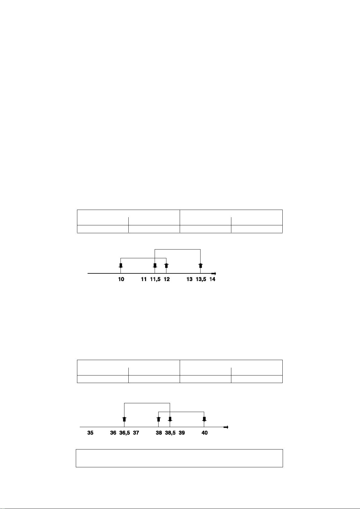
16.2 Water temperature setpoint adjustment
Stage 1
Stage 2
On
Off
On
Off
12
10
13.5
11.5
Stage 1
Stage 2
On
Off
On
Off
38
40
36.5
38.5
R E T U R N T E M P . : - x x . x °
S E T P O I N T : - x x . x °
Water inlet temp.
STP
Stage 2
Stage 1
Water inlet temp.
STP
Stage 2
Stage 1
The control mode is set using parameter P141.
Value 1: set to water return.
Value 2: set to water supply.
Value 3: set to water supply with compensation by water return.
Setpoint 2 allows a similar shift if control adjusted based on the outdoor air (If P127 = Yes or P131 = Yes) or allows the control mode to be
changed if P54 (storage) = Yes.
16.3 Adjustment of water temperature setpoint if P7 ≠ INVERTER
16.3.1 Water return control (P141 = 1):
The temperature used to adjust the setpoint is measured by:
- the inlet sensor on heat exchanger 1 if P2 = air-to-water or reversible air-to-water, if P2 = water-to-water and cooling mode,
- the hot water sensor if P2 = water-to-water and heating mode.
The difference between the control temperature the setpoint is compared to the stage differential and the interstage differential. Depending on
the result, it will be necessary to either turn on an additional stage or to turn one off.
Each stage is turned on at 60-second intervals and the shut off at 1-second intervals.
The related parameters are as follows:
P143: Stage differential
P144: Interstage differential
In cooling mode:
- A call is made for an additional stage if T > Setpoint + SD + (ISD × NSO)
- A call is made to stop a stage if T < Setpoint + (ISD × NSO-1)
Where:
T: Control temperature (measured).
STP: Setpoint
SD: Stage Differential (P143)
Example: Two-stage water chiller
Parameter settings: STP = 10°C, SD = 2 K, ISD = 1.5 K
In heating mode:
- A call is made for an additional stage if T < STP - SD - (ISD × NSO)
- A call is made to stop a stage if T > STP - (ISD × NSO-1)
Where:
T: Control temperature (measured).
STP: Setpoint
SD: Stage Differential (P143)
Example: Two-stage water heater for a water temperature range of 35-40°C.
Parameter settings: STP = 40°C, SD = 2 K, ISD = 1.5 K.
P251: Control setpoint
ISD: Interstage Differential (P144)
NSO: Number of Stages On
ISD: Interstage Differential (P144)
NSO: Number of Stages On
70
Page 73
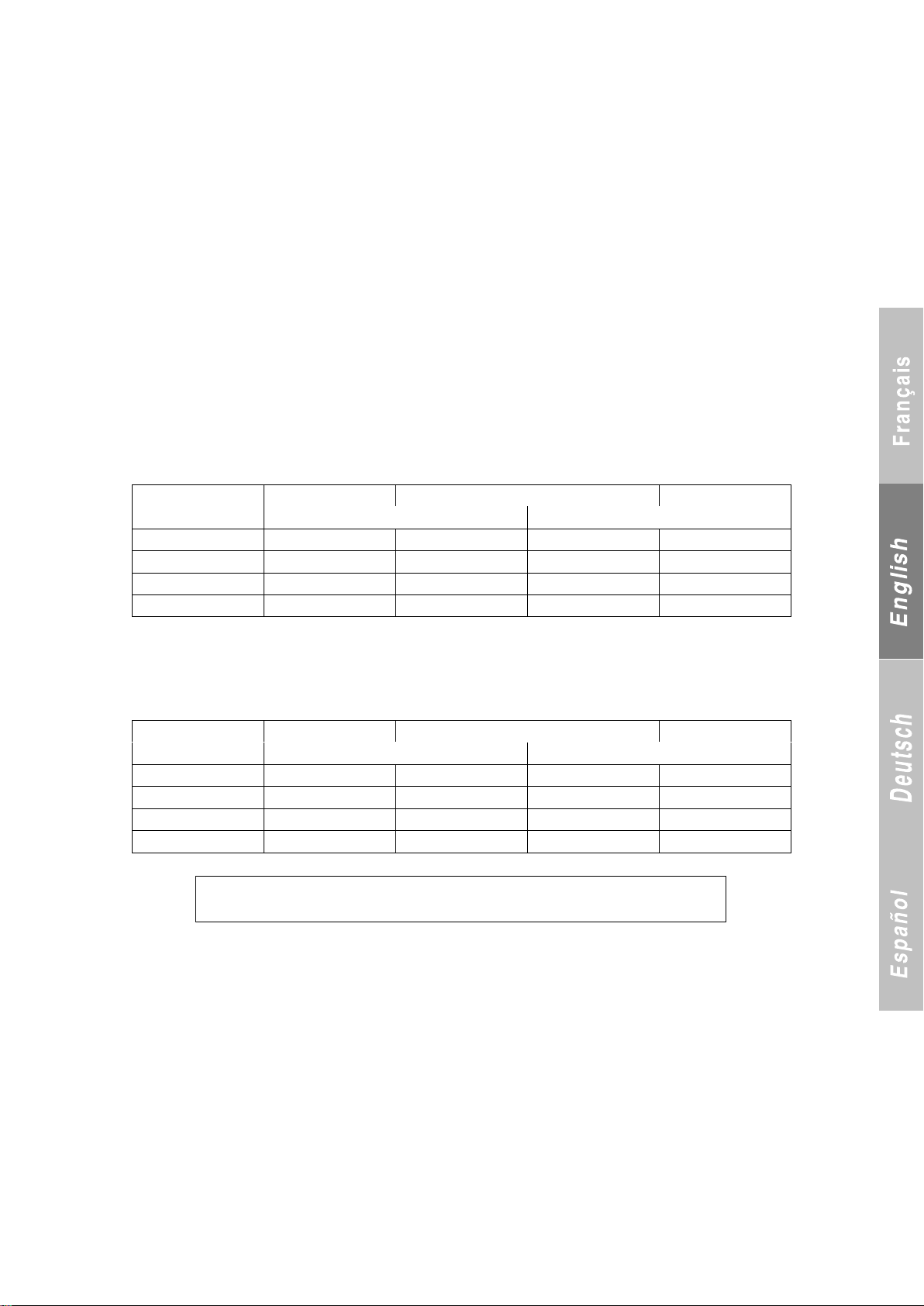
16.3.2 Water supply control (P141 = 2)
P
Stage 1
Stage 2
Stage 1
Off
On
0.5 3 4 6 7 1 4
4.5
5.5
6
1.5
4.33
4.66
5.33
5.66
2
4.5
4.75
5.25
5.5
P
Stage 1
Stage 2
Stage 1
On
Off
0.5
43
44
46
47
1
44
44.5
45.5
46
1.5
44.34
44.66
45.33
45.66
2
44.5
44.75
45.25
45.9
S U P P L Y T E M P . : - x x . x °
S E T P O I N T : - x x . x °
If heating mode is selected with a water-to-water unit, the setpoint is adjusted based on the temperature measured by the hot water supply
sensor. If cooling mode is selected and P6 = 1, the setpoint is adjusted based on the temperature measured by the heat exchanger outlet
sensor. If P6 = 2 in the same mode, it is adjusted based on the temperature measured by the manifold sensor.
The type of control used is PIDτ.
The temperature is measured periodically (τ) then compared to the setpoint and multiplied by a proportional coefficient (P) -- taking into
account the difference between the measurement and the setpoint (D) and the change in the difference between the measurement and the
setpoint (I) -- in order to approach the setpoint quickly.
Formula: DV = P (M-S) t1 + (M-S)*I + [(M-S) t0 - (M-S) t1]*D
M = Measurement, S = Setpoint.
When P146 = 0 and P147 = 0 (standard setting), the PIDτ function becomes PT (the Integral and Derivative functions are disabled)
The related parameters are as follows:
P251: Calculated setpoint
P121: Setpoint 1 in cooling mode
P123: Setpoint 1 in heating mode
P145: P coefficient
P146: I coefficient
P147: D coefficient
P148: T coefficient
In cooling mode:
A call is made for an additional stage if:
DV > +1.0 K for the first stage and +0.5 K for the additional
stages.
Example: Two-stage unit with a 5°C setpoint, where D = 0 and I = 0.
In heating mode:
A call is made for an additional stage if:
DV < –1.0 K for the first stage and -0.5 K for the additional stages.
Example: Two-stage unit with a 45°C setpoint. I = 0 and D = 0.
16.3.3 Adjusting the setpoint to the water supply with compensation on the water return (P141 = 3):
Aim:
Allow the control system to anticipate changes in load on the loop by monitoring for variations in the water inlet temperature.
Action:
Adjusts the controller time delay.
Principle:
The water return temperature is measured: θt0; evaporator in cooling mode, condenser in heating mode at time t0 then t0 + P151.
The calculated temperature variation [θt1 - θt0] is used to define the compensator coefficient.
The PID control polling time then becomes: remaining time × compensator coefficient.
Configuring the compensator coefficient: The compensator coefficient can be set to between 0.1 and 1 (parameter P150).
- If the compensator coefficient = 1 → the function is disabled.
- If the water return temperature variation < 0.5°C → no compensation.
The compensator coefficient is maximum when the temperature variation = 10°C between each time. .
A call is made to turn off a stage if:
DV < –0.5 K for a stage and –1.0 K for the last stage.
A call is made to turn off a stage if:
DV > +0.5 K for a stage and +1.0 K for the last stage.
71
Page 74
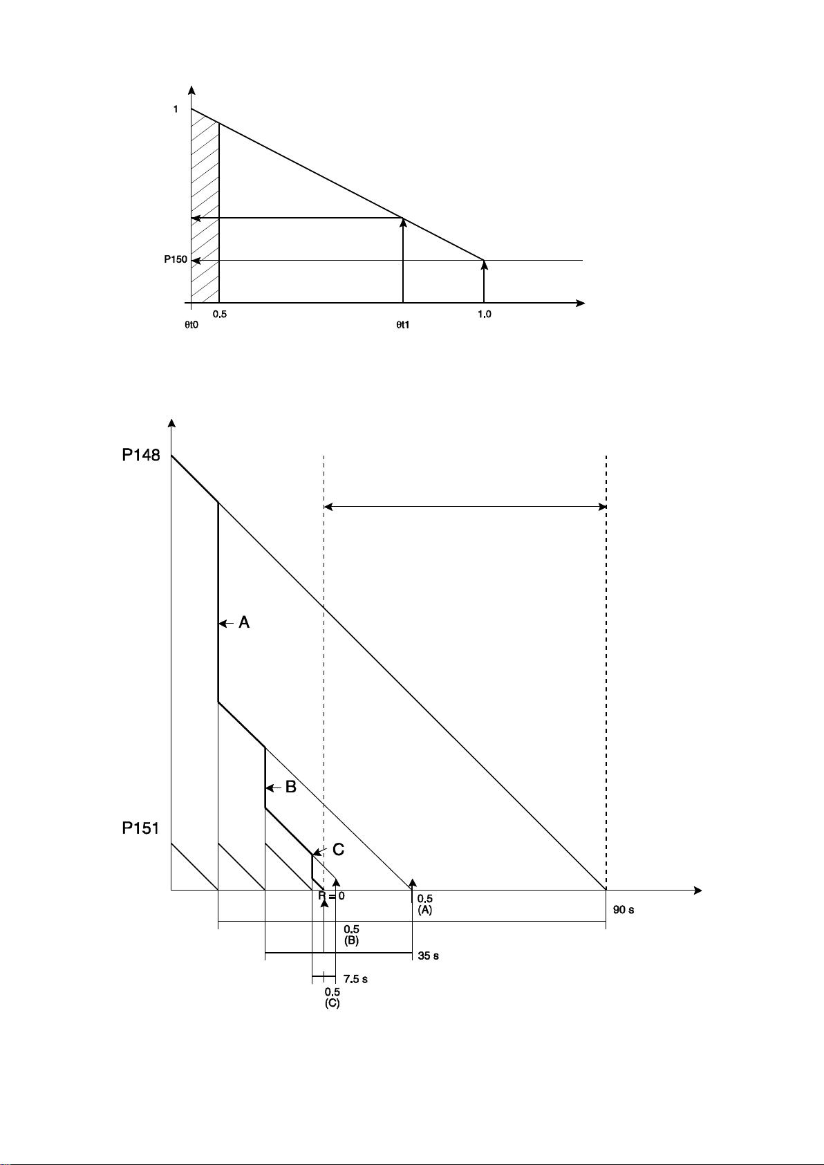
Compensator coefficient diagram:
Action of controller with
compensation
Action of controller
without compensation
Time saved by
compensation
Compensation effect
Temperature variation
Example with a compensation factor of 0.5
Controller time delay P148 = 100 seconds
Compensation time = 10 seconds
A: 1st compensation result. The controller‟s remaining time is
(100 - 10 = 90 seconds) × 0.5 = 45 seconds.
B: 2nd compensation result. The controller‟s remaining time is
(45 - 10 = 35 seconds) × 0.5 = 17.5 seconds
C: 3rd compensation result. The controller‟s remaining time is
(17.5 - 10 = 7.5 seconds) × 0.5 = 3.75 seconds.
R = 0: Moment when the controller‟s time delay = 0.
The two time delays are resynchronised at this moment.
72
Page 75
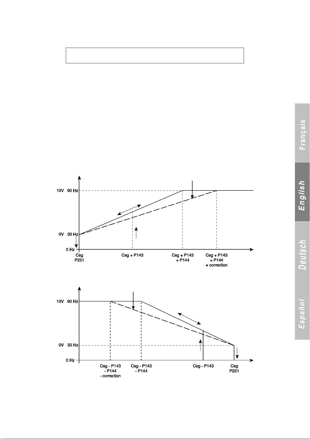
The related parameters are as follows:
S U P P L Y T E M P . : - x x . x °
S E T P O I N T : - x x . x °
Corrected slope
Corrected slope
Csg = STP
Csg = STP
P145: P coefficient
P146: I coefficient
P147: D coefficient
P148: T coefficient (polling time)
P150: Minimum compensation setpoint
P151: Compensation time
16.4 Adjustment of setpoint for the water supply and return temperatures (P141 = 1 or 2) if P7 = INVERTER
The difference between the control temperature the setpoint is compared to the stage differential and the interstage differential. Depending on
the result, it will be necessary to either turn on the compressor and increase its speed or to decrease its speed and turn it off.
In cooling mode
- A call will be made to turn on the compressor if: T > STP + Stage differential
- The compressor rotation speed will be progressively increased if (STP + Stage differential) < T < (STP + Stage differential + Interstage
differential)
Conversely, the compressor speed will be progressively decreased as the water return temperature approaches the setpoint value.
- The compressor will be shut off when T < STP
In heating mode
- A call will be made to turn on the compressor if T < STP + Stage differential
- The compressor rotation speed will be progressively increased if (STP - Stage differential - Interstage differential) < T < (STP - Stage
differential)
- The compressor will be shut off as soon as T > STP
Conversely, the compressor speed will be progressively decreased as the water return temperature approaches the setpoint value
The temperature used to adjust the setpoint is measured by the sensor on the water outlet or inlet of the heat exchanger based on the value of
P141.
In cooling mode:
In heating mode:
Correction management:
Correction is enabled if P7 = Inverter and if P141 = supply and return.
The correction factor is used to prevent the compressor from running during short-cycle protection and too-short runtimes caused by a lack of
inertia in the system.
The correction factor On/Off button is set to „0‟ at power-up.
73
Page 76
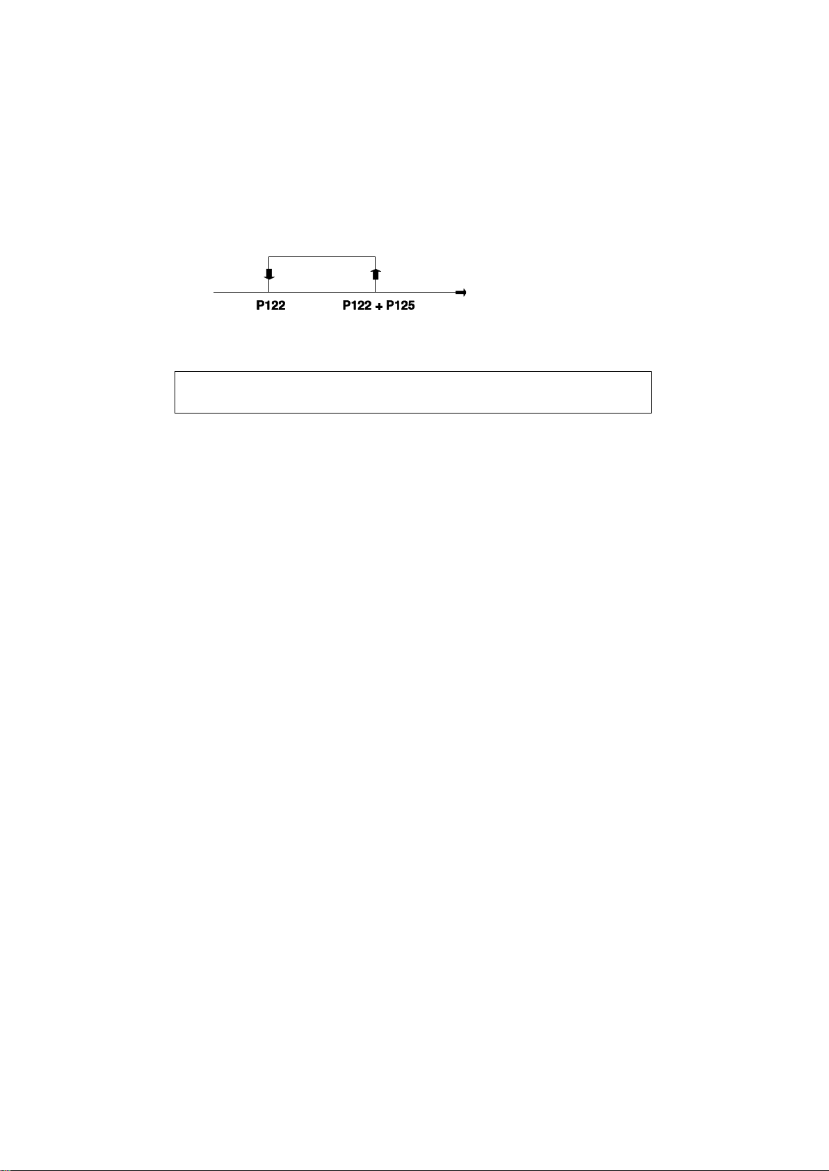
16.5 Storage control
R E T U R N T E M P . : - x x . x °
S E T P O I N T : - x x . x °
Heat exchanger water
inlet temperature
If P154 = No → The control mode remains standard and may be
adjusted to the return or supply line depending on the value of
P141 (control mode).
If P154 = Yes → Storage control is enabled. The control mode is
managed based on the setpoint selected:
This type of control makes it possible to generate maximum capacity at a given time, often when electricity is cheapest.
- One after the other, the compressor stages turn on in 10-second intervals at value P122 + P155. When P122 is reached, the stages are shut
off at the rate of one per second.
- The setpoint 2 LED lights up.
- All limits are maintained.
NOTE: Control based on the outdoor temperature is not available if setpoint 2 is selected. It is, however, available with setpoint 1.
This operating mode is available in cooling mode only.
- If setpoint 1 is selected, the control remains standard and the
mode (supply or return) is selected by P141 (control mode).
- If setpoint 2 is selected, the control automatically switches to
„return with storage‟ mode.
16.6 Control setpoint (P251) management
16.6.1 If P142 (water loop winter protection) = No:
If P120 (setpoint No.) = 1
In cooling mode:
If P127 cooling setpoint adjustment = f (outdoor temperature) = 0
or outdoor sensor fault; Control setpoint = P121
In heating mode:
If P131 heating setpoint adjustment = f (outdoor temperature) = 0
or outdoor sensor fault; Control setpoint = P123
If P120 (setpoint No.) = 2 selected via console
In cooling mode:
If P127 cooling setpoint adjustment = f (outdoor temperature) = 0
or outdoor sensor fault; Control setpoint = P121 or P122
depending on selection on console
In heating mode:
If P131 heating setpoint adjustment = f (outdoor temperature) = 0
or outdoor sensor fault; Control setpoint = P123 or P124
depending on selection on console
If P120 (setpoint No.) = 2 selected via on/off input
The on/off input corresponds to terminals 4-5 on terminal block J6 on the motherboard.
In cooling mode:
If P127 cooling setpoint adjustment = f (outdoor temperature) = 0
or outdoor sensor fault; Control setpoint = P121 if on/off input
open; P122 if on/off input closed.
If P127 = 1 and no fault on outdoor sensor:
In heating mode:
If P131 = 0 or outdoor sensor fault; control setpoint = P123 if
on/off input open; P124 if on/off input closed.
If P131 heating setpoint adjustment = f (outdoor temperature) = 1
and no fault on outdoor sensor:
16.6.2 If P142 (water loop winter protection) = Yes and automatic operation control input open:
The control setpoint = 30°C.
16.6.3. Management of the setpoint based on the outdoor temperature:
P127 cooling setpoint adjustment = f (outdoor temperature) or P131 heating setpoint adjustment = f (outdoor temperature) = 1
This control is used to adjust the cooling or heating setpoint based on the outdoor temperature. In either case, the setpoint with the highest
value is the one that is adjusted.
NOTE: Minimum setting of 5 K between start and end of setpoint drift.
If P127 = 1 and no fault on outdoor sensor, setpoint f (outdoor
temperature) is calculated using P121.
If P131 = 1 and no fault on outdoor sensor, setpoint f (outdoor
temperature) is calculated using P123.
If P127 = 1 and no fault on outdoor sensor; Setpoint f (outdoor
temperature) is calculated using P121 or P122 based on the
selection made via the console.
If P131 = 1 and no fault on outdoor sensor; Setpoint f (outdoor
temperature) is calculated using P123 or P124 based on the
selection made via the console.
- Setpoint f (outdoor temperature) is calculated using P121 if the
on/off input is open.
- Setpoint f (outdoor temperature) is calculated using P122 if the
on/off input is closed.
- Setpoint f (outdoor temperature) is calculated using P123 if the
on/off input is open.
- Setpoint f (outdoor temperature) is calculated using P124 if the
on/off input is closed.
74
Page 77
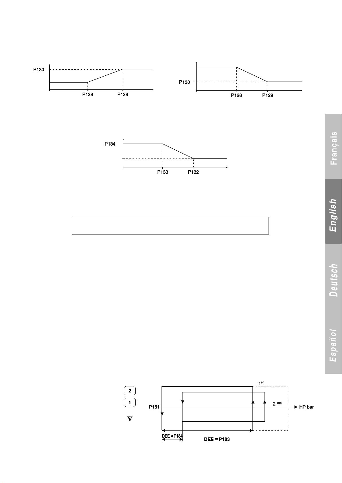
Slope adjustment in cooling mode
S E L F - R E G U L A T I N G
C O N T R O L M O D E
P251 setpoint
Temp.
P251 setpoint
Temp.
P251 setpoint
Temp.
P121
or
P122
P121
or
P122
P123
or
P124
The related parameters are as follows:
P121: Cooling setpoint 1
P122: Cooling setpoint 2
Slope adjustment in heating mode
The related parameters are as follows:
P123: heating setpoint 1
P124: heating setpoint 2
P128: Outdoor temperature at start of drift in cooling mode
P129: Outdoor temperature at end of drift in cooling mode
P130: Maximum setpoint at end of drift in cooling mode
P132: Outdoor temperature at start of drift in heating mode
P133: Outdoor temperature at end of drift in heating mode
P134: Maximum setpoint at end of drift in heating mode
16.7 Automated self-regulating control
If the compressor runtime drops below 3 minutes, the stage differential is increased by 1.0 K for control on the return line (maximum value of 7.0 K).
For control on the supply line, the calculated difference is changed by 1.0 K in order to delay the starting of the compressor. The maximum
shift value is 7.0 K for the first stage and 6.5 K for the following stages.
The following message appears:
If the compressor runtime rises above 5 minutes and the automated self-regulating control is on, the stage differential for the control on the
return line is lowered by 1.0 K until the initial values are reached.
For control on the supply line, the calculated difference by 1.0 K is changed in order to hasten the starting of the compressor until the initial
values are reached.
The function is disabled if the initial values are reached, if the unit is turned off (via On/Off button on console or automatic operation control on
with winter water loop protection off), if a unit fault occurs, if parameter P141 (control mode) is changed and if a power failure occurs.
16.8 Control with AEROCONNECT link in FREE COOLING mode
The thermodynamic unit can control only the cooling return line because the FREE COOLING module driven by AEROCONNECT adjusts the
cooling capacity using its own return line sensor and by retrieving the setpoint set by CONNECT.
17 CONTROL OF CONDENSING PRESSURE FOR AIR-COOLED UNITS
17.1 Control during normal operation or on/off control
In heating mode:
All the fan stages are turned on at maximum speed:
- Once a compressor stage is running on the unit when P11 = intertwined
- Once a compressor stage is running on the circuit when P11 = split.
In cooling mode:
- Control mode is turned on as soon as a compressor stage is running on the circuit.
A) On/Off, where P21 (variable speed control) = No, P10 = Propeller and P11 = Split
The fans turn on once the compressor on the corresponding circuit starts up.
P180 = 2 or 3 corresponds to 2 or 3 fan stages per circuit.
- Fan 1 on circuit 1 will be controlled by stage
1, motherboard terminal block J3 (terminal 5)
- Fan 2 on circuit 1 will be controlled by
stage 2, motherboard terminal block J3
(terminal 6)
- Fan 1 on circuit 2 will be controlled by
stage 1 on circuit 2, ADD 2 board terminal
block J3 (terminal 5)
- Fan 2 on circuit 2 will be controlled by stage
2 on circuit 2, ADD 2 board terminal block J3
(terminal 6)
1er = stage 1, 2ème = stage 2, 1 condenser fan module per circuit = 2 single-phase stages
DEE = Interstage differential
75
Page 78
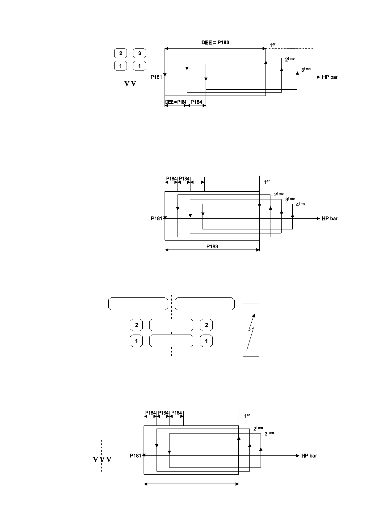
- The two fans 1 on circuit 1 will be controlled by stage 1 on circuit 1, motherboard terminal block J3 (terminal 5)
1 “common”
3 “common”
Ref. circuit
Ref. circuit
2 condenser fan modules per circuit = 3 single phase stages
- Fan 2 on circuit 1 will be
controlled by stage 2 on circuit 1,
motherboard terminal block J3
(terminal 6)
- Fan 3 on circuit 1 will be
controlled by stage 3 on circuit 1,
ADD 2 board terminal block J3
(terminal 7)
- The two fans 1 on circuit 2 will be
controlled by stage 1 on circuit 2,
ADD 2 board terminal block J3
(terminal 5)
Fan 2 on circuit 2 will be
controlled by stage 2 on circuit 2,
ADD 2 board terminal block J3
(terminal 6)
- Fan 3 on circuit 2 will be controlled by stage 3 on circuit 2, 1er =: stage 1, 2ème = stage 2, 3ème = stage 3,
ADD 2 board terminal block J3 (terminal 8) DEE = Interstage differential
B) On/Off, where (P21 = No), P10 = propeller and P11 = intertwined
- Control mode is turned on as soon as a compressor stage is running on the unit.
- If one of the two circuits is shut off (by a temporary or permanent fault, or control fault or other fault), the fan continues to operate using the
pressure from the circuit this is still on.
When both refrigerating circuits are on, the fans are turned on and off by the circuit with the highest pressure.
Fan 1 will be controlled by stage 1, motherboard
terminal block J3 (terminal 5)
Fan 2 will be controlled by stage 2, motherboard
terminal block J3 (terminal 6)
1er = stage 1,
2ème = stage 2,
3ème = stage 3,
4ème = stage 4
C) On/Off, where (P21 = No), P10 = propeller and P11 = intertwined
- Control mode is turned on as soon as a compressor stage is running on the unit.
- Stages 1 and 2 are controlled by each circuit.
- Common stage 1 is turned on as soon as the first control stage for circuits 1 and 2 is turned on.
- Common stage 3 is turned on as soon as the third control stage for circuits 1 and 2 is turned on.
Fan 1 on circuit 1 will be controlled by stage 1, motherboard
terminal block J3 (terminal 5)
Fan 2 on circuit 1 will be controlled by stage 2, motherboard
terminal block J3 (terminal 6)
Fan 1 on circuit 2 will be controlled by stage 1 on circuit 2, ADD
2 board terminal block J3 (terminal 5)
1er: stage 1
2ème: stage 2
3ème: stage 3
Fan 2 on circuit 2 will be controlled by stage 2 on circuit 2, ADD
2 board terminal block J3 (terminal 6)
"Common" fan 1 will be controlled by common stage 1, ADD
2 board terminal block J3 (terminal 7)
"Common" fan 3 will be controlled by common stage 3, ADD
2 board terminal block J3 (terminal 8)
76
Page 79
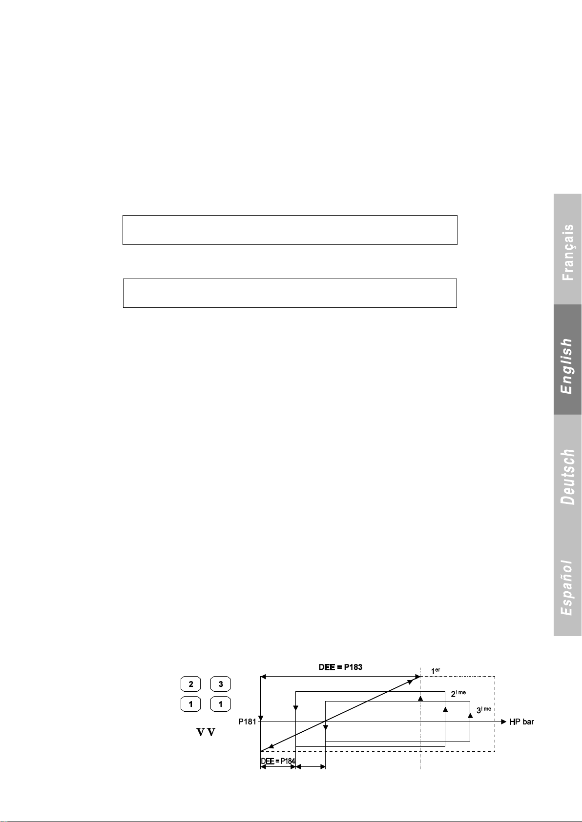
17.2 Forced and self-adjusting control
H P x P R E S S U R E C O N T R O L
S T A G E 1 O N L Y
H P P R E S S U R E C O N T R O L
S T A G E 1 O N L Y
The condensing pressure control can be forced in cooling mode in two cases:
Case 1: If HP > P54 – P195 – 0.5, the fans run at maximum speed for 30 minutes and the stages turn on at 1-second intervals. This 30-
minute runtime applies in case 2 as well.
- If intertwined coils are used, the first fan is turned on by the sensor that reads the highest value.
- If split coils are used, the function is managed by each circuit.
- If mixed coils are used, fans 1 and 2 are managed by each circuit. In the case of common fans 1 and 3, they are turned on by the sensor that
reads the highest value.
Case 2: Management of control stage 1 (case of propeller fans with on/off control).
If fan stage 1 turns on more than 5 times in 10 minutes while the other stages are off, increase the stage differential by 4.5 b to shut off the
other stages. Normal control mode resumes (extra 4.5 b pressure eliminated and other stages allowed to turn on) if HP > P54 - P195 - P196 or
if HP > P181 + P183 for 10 minutes.
If the common fan 1 stage (common to both circuits) turns on more than 5 times in 10 minutes and the other higher stages on both circuits are
off, increase the stage differential by 4.5 b on both circuits.
The following message appears when P11 = split and mixed if stage 1 or 4 turns on more than 5 times in 10 minutes:
The following message appears when P11 = intertwined and mixed if stage 3 turns on more than 5 times in 10 minutes:
17.3 Fan speed control
The speed of the fans is controlled by the HP pressure sensor and the 0-10 V outputs on the motherboard and additional board 2. This control
functions in cooling mode only in order to reduce the sound level of the units. In heating mode, the fans run at maximum speed once a
compressor stage turns on.
If P21 = 2 or 3 (speed control with energy or acoustic optimisation) the speed of fan 1 on each circuit will be controlled; the other fans will be
adjusted to P180 by the on/off inputs.
The moment the fan starts in speed control mode and the moment the other stages are turned on must be separated by an interval of
3 seconds.
Variable speed drive (VSD):
In order for it to adjust the speed based on the 0-10 V signal, the variable speed drive selected must first be supplied electrically and informed
of the direction of rotation.
VSD power supply:
Power will be supplied, via the power contactors, by the control for fan 1 on circuit 1 (terminal 5 on terminal block J3), the control for fan 1 on
circuit 2 (terminal 6 on terminal block J3 on additional card 2) and the control for fan 1 common to both circuits (terminal 5 on terminal block J3
on additional board 2).
In both heating and cooling mode, these three outputs must be powered as soon as the unit is turned on by pressing the On/Off button on
the console or by turning off the Automatic Operation control. They will shut off after the Automatic Operation control is turned on or if the
On/Off button on the console is pressed.
Authorisation of VSD operation:
External VSDs (ALTIVAR) will not be controlled by the software. Instead, they will be controlled electromechanically via two auxiliary relays on
the KGs of the compressors (as soon as a compressor turns on, the associated relay sends the information to the VSD). As a result, running
the VSDs without the compressors will not be possible.
In the case of electronically commutated fans (built-in variable speed drive), authorisation for the VSDs to turn on is given by the board when
the fan contactor outputs are in the On position (no relay needed).
17.3.1 Fan speed control with split coils (P11 = split):
This configuration requires a variable speed drive for each circuit.
- 0-10 V output, stage 1, circuit 1, terminals 1-2 on motherboard terminal block J2
- 0-10 V output, stage 1, circuit 2, terminals 2-1 on terminal block J6 of additional board 2
Speed control mode is turned on as soon as the circuit is on.
a) P21 = 2 with acoustic optimisation
1 condenser fan module per circuit
= 1 stage (1 fan) with speed control
+ 1 single-speed stage (same as
standard)
2 condenser fan modules per
circuit = 1 stage (2 fans) with
speed control + 2 single-speed
stages (same as standard)
1er: stage 1, 2ème: stage 2
3ème: stage 3,
DEE = Interstage differential
77
Page 80
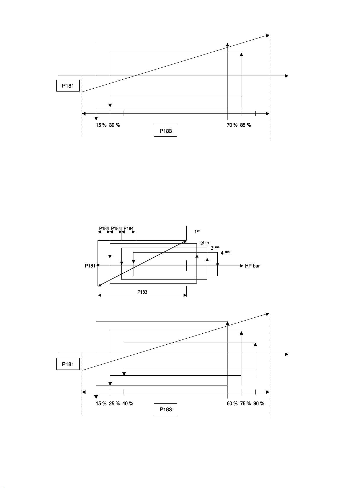
b) P21 = 3 with energy optimisation (Available only if P42 = ALCO or CIAT)
Stage 1
Stage 2
Stage 3
Stage 1
Stage 2
Stage 3
Stage 4
If P180 = 3 stages: 15-30% and 70-85% for stages 2-3
If P180 = 2 stages: 20 and 80% for stage 2
The values of P181 and P183 must be set.
P181 = 17.8 b for R410A, 12 b for R407C, 11.0 b for R22 and
In this case parameters P181 and P183 can be adjusted (resolution of 0.1) and parameter P184 becomes needless and therefore inaccessible.
The minimum value of P181 becomes 16 bar for R410A.
The minimum value of P183 becomes 8 bar for R410A.
17.3.2 Fan speed control with intertwined coils (P11 = intertwined):
Speed control mode is turned on as soon as the unit is on.
With 1 circuit running: speed is controlled by the circuit‟s HP sensor.
With 2 circuits running: the speed is controlled by the sensor with the highest pressure.
a) P21 = 2 with acoustic optimisation
1er: stage 1
2ème: stage 2
3ème: stage 3
4ème: stage 4
b) P21 = 3 with energy optimisation (Available only if P42 = ALCO or CIAT)
If P180 = 4 stages: 10-25-40% and 60-75-90% for stages 2-3-4
If P180 = 3 stages: 15-30% and 70-85% for stages 2-3
If P180 = 2 stages: 20 and 80% for stage 2
The values of P181 and P183 must be set.
In this case parameters P181 and P183 can be adjusted (resolution of 0.1) and parameter P184 becomes needless and therefore inaccessible.
- The minimum value of P181 becomes 16 bar for R410A. - The minimum value of P183 becomes 8 bar for R410A.
6.8 b for R134a
P183 = 7.8 b for R410A or 5.5 b for R407C, 5.0 b for R22 and
3.8 b for R134a
P181 = 17.8 b for R410A, 12 b for R407C, 11 b for R22 and 6.8 for R134a
P183 = 7.8b for R410A or 5.5b for R407C, 5.0b for R22 and 3.8 b for
R134a
78
Page 81
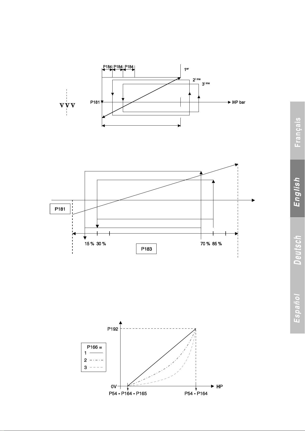
Stage 1
Stage 2
Stage 3
17.3.3 Fan speed control with mixed coils (P11 = mixed)
- 0-10 V output, stage 1, circuit 1, terminals 1-2 on motherboard
terminal block J2
- 0-10 V output, stage 1, circuit 2, terminals 2-1 on terminal
block J6 of additional board 2
- 0-10 V output, stage 1 common to circuits 1 and 2, terminals 2-3
a) P21 = 2 with acoustic optimisation
b) P21 = 3 with energy optimisation (Available only if P42 = ALCO or CIAT)
If P180 = 3 stages: 15-30% and 70-85% for stages 2-3
If P180 = 2 stages: 20 and 80% for stage 2
The values of P181 and P183 must be set.
P181 = 17.8 b if R410A, 12 b if R407C, 11.0 b if R22 and 6.8 b if R134a
P183 =7.8 b if R410A or 5.5 b if R407C, 5.0 b if R22 and 3.8 b if R134a
17.3.4 Fan speed control if P7 = INVERTER:
- The rotation speed is limited by parameter P192 (default value of 7.8 V). It can be set at between 5 and 10 V (resolution of 0.1 V).
If P7 = Inverter, the standard setting value of P181 becomes 13.4 bar as long as LP < 8.3 bar.
If the LP rises above this value, the HP control setpoint is becomes equal to P181 + 4.4 bar.
- The HP control setpoint returns to P181 when the LP drops to < 7.8 bar.
- The maximum shift in the HP STP is 33.9 bar (recovery function included).
17.3.5 Forced control of variable-speed fans:
The condensing pressure control can be forced in cooling mode in two cases:
- If HP > P54 – P195 – 0.5, the fans run at maximum speed for 30
minutes and the stages turn on at 3-second intervals.
- During defrosting in order to defrost the coils as quickly as
Adjustment adopted during defrosting (once the cycle has been reversed by the reversing valve). The other fans are off during this time.
of terminal block J6 of additional boards 2
- Common stage 1 is controlled by the highest value of the two
signals on circuits 1 and 2
- Common stage 3 is turned on as soon as the third control stage
for circuits 1 and 2 is turned on.
In this case parameters P181 and P183 can be adjusted (resolution
of 0.1) and parameter P184 becomes needless and therefore
inaccessible.
- The minimum value of P181 becomes 16 bar for R410A.
- The minimum value of P183 becomes 8 bar for R410A.
possible. The HP will have to be as high as possible without
turning on the protections.
- Parameter P166 (3 by default) is used to adjust the fan control.
79
Page 82
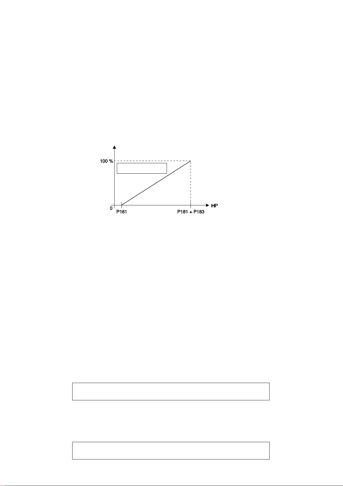
17.3.6 Speed control of centrifugal fans (P10 = Centrifugal):
P R E S S U R E C O N T R O L
H P S H I F T E D
P 2 9 T O T A L
R E C O V E R Y NO
Fans 1 and 2
P21 is hidden. This configuration is not available. The HP is controlled via the air blades. Refer to the section on controlling the air blades.
17.3.7 Speed control of electronically commutated pressure fans (P10 = Pressure):
This function provides the same functionalities as the variable speed drive described above with the added possibility of allowing the customer
to limit the speed of the fans in order to lower the sound level or best adjust the available pressure..
This function is enabled when:
P10 = pressure P2 = Air-to-Water or Reversible Air-to-Water,
P180 (No. of HP control stages) = 1 = hidden,
In cooling mode, the speed is controlled by the HP pressure sensor and the 0-10 V outputs on the main board. In heating mode, the fans run
at maximum speed once a compressor stage turns on.
If several electronically controlled fans are on the same circuit, the 0-10 V supplies must be wired in series (two maximum).
The speed of the fans is limited by parameter P192 which is set by default to 8 V but may be adjusted to between 5 and 10 V in increments of 0.5 V.
Control:
Regardless of the value of P11, the control system is on as soon
as a compressor stage is on.
- One circuit used: The fans are controlled in response to the high
pressure on the circuit.
The cases for forced control and control during defrosting are the same as those described in section 17.3.5.
P21 (speed control) = 2 hidden,
P181 and P183 = visible and P11 (coil type) visible.
- Two circuits used: The fans are controlled in response to the
highest pressure read by either sensor on the two circuits.
The fans are controlled simultaneously.
17.4 Low Noise control (single-fan units only – Aquaciat2)
This function is available only on single-fan units, i.e. if P180 = 1. To see if the function is enabled, go to parameter P191 (Low Noise
operation), which is set to „Yes‟ by default. Visible only if P180 = 1.
This function disappears if a variable speed drive is used (P21 = Yes).
The fan must be shut off when switching from LS to HS and back. To do so, open contact J3, terminal 2 before actuating J3, terminal 3.
LS is obtained by energising fan relay 1 (terminal 2 on terminal
block J3) and fan relay 2 remains open.
In cooling mode:
- If P191 (LOW NOISE) = Yes:
As long as HP < P54 - P195 – 3 b, low speed must remain on. When the HP rises above this value, shift to high speed (cut off terminal 2,
terminal block J3; cut off terminal 3 on terminal block J3; restore terminal 2 on terminal block J3). LS is resumed when HP < P54 - P195 – 7 b.
- If P191 (LOW NOISE) = No:
The system must be switched to high speed very quickly in order to deliver a maximum amount of power to the customer.
- If HP > P181 + P183, turn on LS
- If HP > P181 + P183 + P184, turn on HS
The system does not switch to LS before turning off. It is shut off when HP = P181.
- Forced and self-adjusting control:
Case1: On if P64 (optimised frost protection) = No
- If HP > P54 - P195 - 0.5, the fans are already running at HS unless the frost limiter on the water or refrigerant line is on. In this case, remain
at LS and let the HP protection do its job.
Case2: Regardless of the value of P191
- If the fan turns on more than 5 times in 10 minutes, increase the stage differential by 4.5 b. Normal control mode resumes (extra 4.5 b
pressure eliminated) if HP > P54 - P195 - P196 or if HP > P181 + P183 for 10 minutes.
The following message appears when P180 = 1 and stage 1 turns on more than 5 times in 10 minutes:
In heating mode:
The fan runs at HS.
HS is obtained by energising fan relay 2 (terminal 3 on terminal
block J3) and fan relay 1 remains open.
17.5 Total recovery control
The total recovery function and its associated parameters (P29 and P193) are accessible only if P2 = air-to-water:
80
Page 83
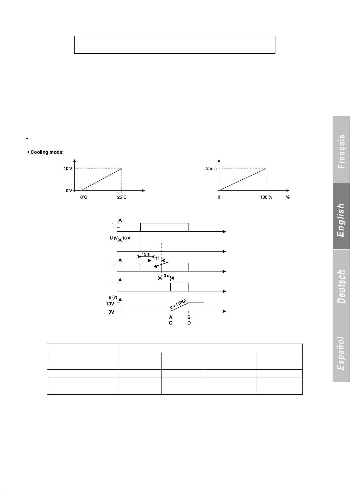
- P193 visible If P29 = Yes
P 1 9 3 H P S T P S H I F T
D U R I N G R E C O V E R Y
Diagram 1
Diagram 2
Value A
Value B
Value C
Value D
R22/R407C
12b
16b
19b
23b
R134a
7.5b
10.5b
12.5b
15.5b
R404a
14b
18b
20b
23b
R410a
20b
25b
30b
37b
Time
State of
compressors
Time
Time
Time
Bar
Condensing pressure
Diagram 1
Diagram 2
Voltage on actuator
terminals with
compressor off
Compressor startup order
Fans on if HP1 or
HP2 < A
Prepositioning
Recovery input (10/11 on J6) will be used by the customer to define the operating mode:
STANDARD or RECOVERY
Two operating modes are possible if parameter P29 = Yes:
Contact J6 - 10/11 on motherboard open without recovery:
- Standard fans controlled based on the values of P10, P20 and P21
B) Contact J6 - 10/11 motherboard closed with recovery:
- The turning-on of the fans is shifted using parameter P193 → The HP control setpoint then becomes equal to P181 + P193
- The control logic will then be identical to standard control using the values of P10, P20 and P21.
17.6 Management of the air blades if P10 = Centrifugal
This "all season" option will be offered for air-to-water units with centrifugal fans.
- If P20 = Yes:
Heating mode: The centrifugal fan starts up 3 seconds after the compressor, regardless of the HP1 and HP2 values.
The fan is turned off during defrosting
. The air blades are controlled by the 0-10 V output (terminals 1-2 on terminal block J2 on motherboard) as shown below:
One-circuit unit (or fault on one circuit of a two-circuit unit):
Adjust as shown in diagram 1.
Two-circuit unit and if the compressor on circuit 2 running for at least 5 seconds:
- If HP1 or HP2 < A → Control shown in diagram 1 and taking into account the sensor with the lowest pressure.
- If A < (HP1 and HP2) < C → Control shown in diagram 1 and taking into account the sensor with the lowest pressure.
- If HP1 or HP2 > C → Control shown in diagram 2 and comparison of:
. Voltage U1 = Diagram 1 (lowest HP)
. Voltage U2= Diagram 2 (highest HP)
And voltage U adjusted to highest value of U1 and U2.
- If HP1 and HP2 > C → Control shown in diagram 1 and taking into account the sensor with the highest pressure.
- P20 = No:
Output = 0 V
81
Page 84
18 CONTROL OF CONDENSING PRESSURE FOR WATER-TO-WATER UNITS
P 2 2 5 M I N . A I R T E M P .
I N H E A T I N G M O D E - x x °
M A C H I N E O F F I N H T G M O D E
O U T T E M P . T O O L O W
E L E C A U X C T R L
O U T T E M P . T O O L O W
B O I L E R C O N T R O L
O U T D O O R T E M P . T O O L O W
P 2 2 5 M I N . A I R T E M P .
I N H T G M O D E D I S A B L E D
P 2 2 5 . 1 M A X . A I R T E M P .
I N C L G M O D E + x x °
1) Operation with a two-way valve
If municipal wastewater is used to cool the condenser, we
recommend installing the two-way valve so as to be able to set
the condensing pressure to a value that will ensure correct
operation of the unit and save on cooling water.
Set P26 to „two-way valve‟. The valve will open linearly from P197
to P198 based on the high pressure.
For more details, refer to the instruction manual supplied with the
kit. To obtain high cooling capacity, set P197 and P198 to their
lowest values. To save on water, set P197 and P198 to their
highest values.
These adjustments depend solely on your installation. It is
essential that you ensure the correct operation of your unit.
2) Operation with a three-way valve
We recommend installing our three-way valve kit if our units are
used with cooling towers. This valve will allow you to adjust the
condensing pressure better and thus optimise your unit‟s
performance. Set P26 to „three-way valve‟. The valve will open
linearly from P197 to P198 based on the water return
temperature. For more details, refer to the instruction manual
supplied with the kit.
19 RESTRICTION OF OPERATION OF THE MACHINES BASED ON THE OUTDOOR
TEMPERATURE
19.1 Restriction to the minimum air temperature in heating mode
- This parameter can be set to between -25°C and 5°C in 1°C increments.
- Default setting:-10°C if P119 ≠ Cooling where P2 = 3 reversible air-to-water and P7 ≠ INVERTER -20°C if P119 ≠ Cooling where P2 = 3
reversible air-to-water and P7 = INVERTER
This function is disabled if at least one circuit is being defrosted.
The thermodynamic unit shuts off once the outdoor temperature P225. The auxiliary heaters or the boiler are substituted for the
thermodynamic control stages. The (thermodynamic) unit restarts once the temperature rises to above P225 + 2K.
Display in heating mode and if auxiliary electric heater P22 = No and P111 ≠ Boiler:
If a fault occurs:
- Fault stored in memory in case of a mains power failure
- Fault saved in fault memory
Display in heating mode and if auxiliary electric heater P22 = Yes:
If a fault occurs:
- Fault not stored in memory if a mains power failure occurs
- Fault not saved in memory if a mains power failure occurs
Display in heating mode and if P111 = Boiler:
If a fault occurs:
- Fault not stored in memory if a mains power failure occurs
- Fault not saved in memory if a mains power failure occurs
- To disable this function:
- Simply press the - button until the maximum value of the parameter appears. Below this value, the following message appears:
- To turn off the function, simply press Enter.
- To re-enable it, simply enter a value of between -25°C and +5°C and press Enter.
- Relay in On position
- Unit fault LED lit steady.
- Fault relay in Off position
- Unit fault LED off.
- Fault relay in Off position
- Unit fault LED off.
19.2 Restriction to the maximum air temperature in cooling mode
Visible only if P2 = air-to-water or reversible air-to-water and cooling mode
- This parameter can be set to between 35°C and 50°C in 1°C increments.
- Default setting: DISABLED
The unit shuts off once the outdoor temperature ≥ P225.1.
The unit restarts once the temperature rises back to above P225.1- 2K.
82
Page 85
Fault message:
M A C H I N E O F F I N C L G M O D E
O U T T E M P . T O O H I G H
P 2 2 5 . 1 M A X . A I R T E M P .
I N C L G M O D E D I S A B L E D
P 2 2 5 . 2 M A X . A I R T E M P .
I N H T G M O D E - x x °
M A C H I N E O F F I N H T G M O D E
O U T T E M P . T O O H I G H
P 2 2 5 . 2 M A X . A I R T E M P .
I N H T G M O D E D I S A B L E D
P 2 2 5 .3 M I N . A I R T E M P .
I N C L G M O D E + x x °
M A C H I N E O F F I N C L G M O D E
O U T T E M P . T O O L O W
If a fault occurs:
- Fault stored in memory in case of a mains power failure
- Fault saved in fault memory
To disable this function:
- Simply press the + button until the maximum value of the parameter appears. Above this value, the following message appears:
- To turn off the function, simply press Enter.
- To re-enable it, simply enter a value of between 35°C and 50°C and press Enter.
- Relay in On position
- Unit fault LED lit steady.
19-3- Restriction to the maximum air temperature in heating mode:
This function is used to prohibit the machine operating in heating mode when the outdoor temperature rises above a configurable value.
This function is disabled if at least one circuit is being defrosted
Visible if P2 = water-to-water and reversible air-to-water when P119 ≠ 1 (Cooling only)
- This parameter can be set to between -5°C and 20°C in 1°C increments.
- Default setting: DISABLED
The unit shuts off once the outdoor temperature ≥ P225.2
The unit restarts once the temperature rises back to above P225.2 - 2K.
Display
This limit is not managed as a fault if the machine is shut off because of it:
- Not stored in memory if a mains power failure occurs
- Fault not saved in memory
To disable this function:
- Simply press the + button until the maximum value of the parameter appears. Below this value, the following message appears:
- To turn off the function, simply press Enter.
- To re-enable it, simply enter a value of between -5°C and +20°C and press Enter.
- Fault relay in Off position
- The unit fault LED is off
19-4- Restriction to the minimum air temperature in cooling mode:
This function is used to prohibit the machine operating in cooling mode when the outdoor temperature rises above a configurable value.
Visible if P2 = Reversible Water-to-Water and Air-to-Water when P119 ≠ 2 (Heating only)
- This parameter can be set to between -20°C and 12°C in 1°C increments.
- Default setting: DISABLED
The unit shuts off once the outdoor temperature ≤ P225.3.
The unit restarts once the temperature rises back to above P225.3 + 2K.
Display
This limit is not managed as a fault if the machine is shut off because of it:
- Not stored in memory if a mains power failure occurs
- Fault not saved in memory
- Fault relay in Off position
- The unit fault LED is off.
83
Page 86
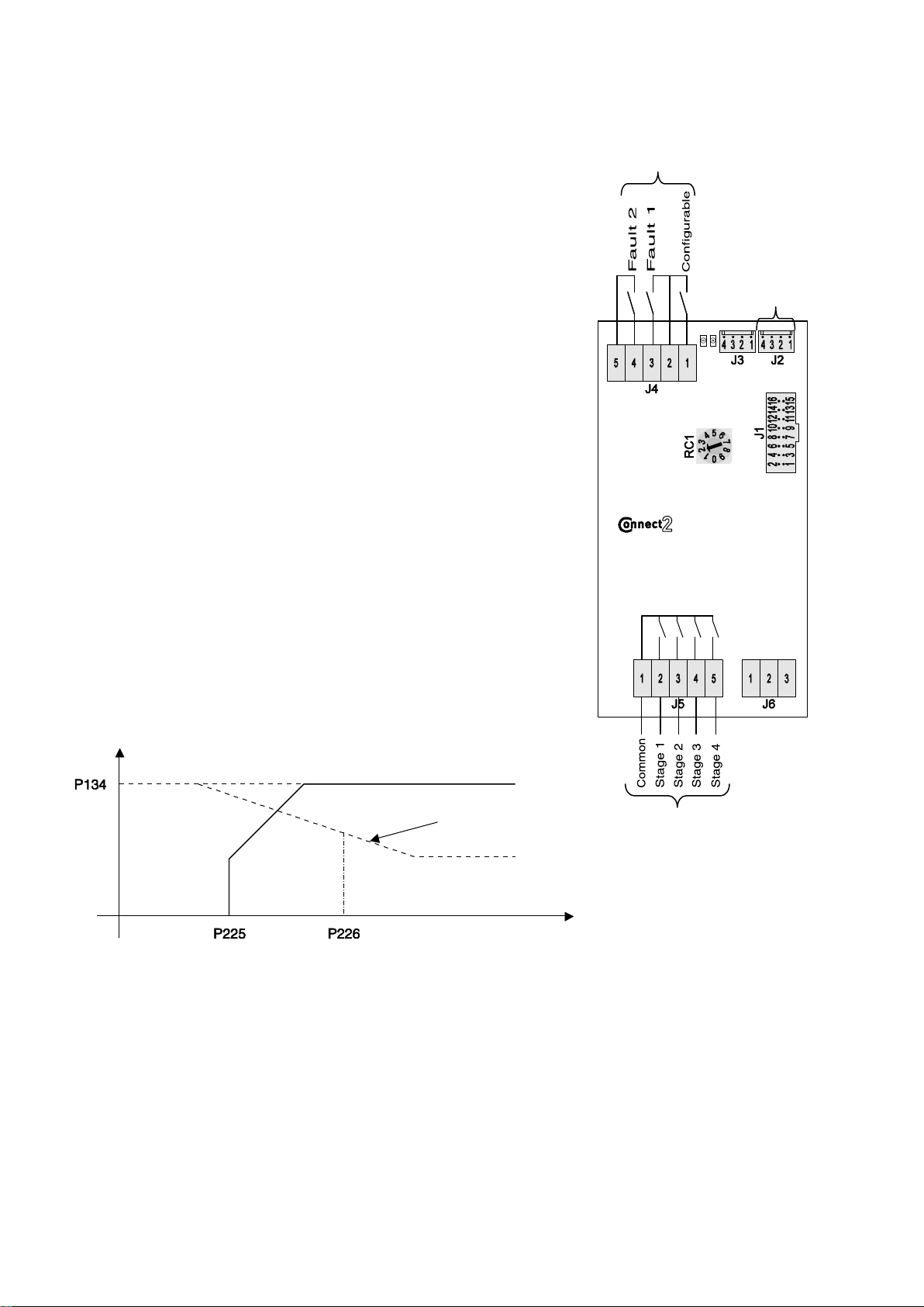
20 MANAGEMENT OF THE AUXILIARY HEATER BOARD AND THE ELECTRIC AUXILIARY
Setpoint
Electric
auxiliaries
only
Heat pump
and electric
auxiliaries
Heat pump only
Setpoint
= f (Text) in °C
Outdoor air temperature (°C)
Outputs
Bus link with
CONNECT 2
board
Inputs
HEATERS
The auxiliary electric heater board is the ADDitional board 1 with the rotary switch
set to position 2.
It is used to obtain up to four additional control stages in heating mode.
Example:
When used on a unit with two control stages, the board brings the total number
of stages to six (two thermodynamic stages and four electric stages).
Although the electric stages are managed as control stages, the last control stages
will turn on last.
The electric stages are turned on if:
- the thermodynamic power is insufficient
- faults occur on the compressor stages
- the outdoor temperature is less than P225
- the water return temperature is too low to allow defrosting
The electric stages are shut off if a water flow fault occurs.
The auxiliary electric heater board has three separate on/off inputs:
- Input 1 → ADDitional board 1, auxiliary electric heaters used, terminal block J4
between terminals 2-3 (if the input is open, the electric auxiliary heaters are shut
off by fault 1 and the corresponding message appears).
- Input 2 → ADDitional board 1, auxiliary electric heaters used, terminal block J4
between terminals 4-5 (if the input is open, the electric auxiliary heaters are shut
off by fault 2 and the corresponding message appears).
- Input 3 → ADDitional board 1, auxiliary electric heaters used terminal block J4
between terminals 1-2
Value of P113:
- If P113 = DISABLED, the input is disabled regardless of its state.
- If P113 = LOAD SHEDDING, two cases apply:
1) The input is open: the electric auxiliary heaters operate normally
2) The input is closed: the electric auxiliary heaters are turned off
- If P113 = OVERRIDE:
1) The input is open: the thermodynamic stages and the electric auxiliary heaters
operate normally
2) The input is closed: the thermodynamic stages are turned off
The outputs always close in the same order (1, 2, 3, 4) and always open in
the reverse order (4, 3, 2, 1).
Management of the electrical auxiliary heaters under normal operation:
- If the air temperature ≥ P226: heat pump alone
- If the air temperature < P226: heat pump and electric auxiliary heaters. If a call is made for control, the thermodynamic control stages are the
first stages.
- If the air temperature < P225: the heat pump is shut off and only the electric stages operate.
Management of the electric auxiliary heaters when the thermodynamic control stage is shut off by a setpoint corrected by
the discharge protection:
- The electric stages take the place of the thermodynamic stages
and become the first control stages, and the outdoor air
temperature at that exact moment is stored in memory.
- The auxiliary heaters are set to the initial setpoint if P131
(setpoint adjustment based on outdoor temperature) = No. They
are set to the calculated setpoint if P131 = Yes.
- The thermodynamic stages adjust to the setpoint corrected by
the discharge temperature protection.
- Whether the machine is on or off, the corrected setpoint will
increase by 1°C for an equivalent rise in the air temperature
Management of the electric auxiliary heaters when the machine is shut off by a general fault:
The electric stages take the place of the thermodynamic stages.
until:
. Initial setpoint if P131 = No
. Calculated setpoint if P131 = Yes
- When the air temperature is > than the air temperature stored in
memory + 2, the thermodynamic stages revert to being the first
control stages and the electric stages are the last and adjust to
the original setpoint:
. Initial setpoint if P131 = No
. Calculated setpoint if P131 = Yes
84
Page 87
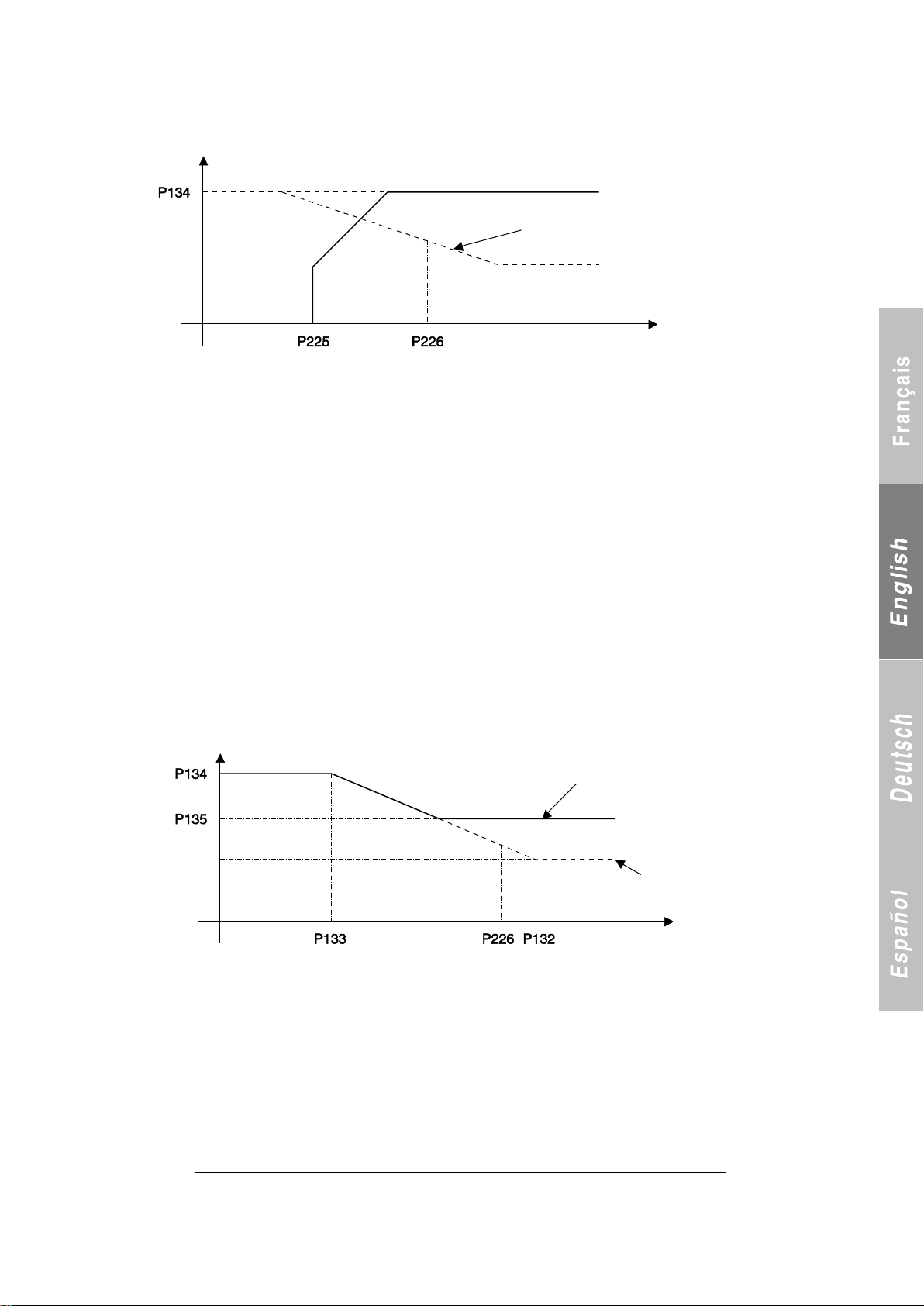
21 MANAGEMENT OF THE BACK-UP BOILER
12- M A S T E R / S L A V E
Setpoint
Boilers only
Heat pump
and boiler
Heat pump only
Setpoint
= f (Text) in °C
Outdoor air temperature (°C)
Setpoint
= f (Text) in °C
Outdoor air temperature (°C)
Minimum boiler setpoint
Setpoint
P123
or
p124
If P111 = Boiler
Management under normal operation:
- If the air temperature ≥ P226: heat pump alone
- If the air temperature < P226: heat pump and boiler. If a call is
made for control. The thermodynamic control stages are the
first stages.
Management of the electric auxiliary heaters when the thermodynamic control stage is shut off by a setpoint corrected by the
discharge protection:
- The boiler contact (terminals 2-3 on terminal block J3 on the
main board) is closed, the outdoor air temperature at the time of
closing is stored in memory. P226 takes on the value of the
outdoor temperature if it is lower.
- The boiler is set to the initial setpoint if P131 (setpoint
adjustment based on outdoor temperature) = No. It is to the
calculated setpoint if P131 = Yes
- The thermodynamic stages adjust to the setpoint
Management of the boiler when the machine has been shut off by a general fault:
- Boiler contact closed
- Control with a minimum setpoint P135 = 50°C
Management of the boiler when the machine has been shut off by a water flow fault:
(Depending on state of P27: pump controlled by boiler operation)
- If P27 = Yes, boiler operation authorised. - If P27 = No, the boiler is shut off.
- If the air temperature < P225: heat pump shut off and boiler
turned on.
corrected by the discharge temperature protection.
- Whether the machine is on or off, the corrected setpoint will
increase by 1°C for an equivalent rise in the air temperature until:
. Initial setpoint if P131 = No
. Calculated setpoint if P131 = Yes
- The boiler relay is open when the air temperature > P226 + 2.
By default, this minimum setpoint must be adjusted based on the
technology of the boiler.
22 MASTER/SLAVEE CONTROL
22.1 Case of two parallel-connected machines
For a master/slave setup involving two parallel-connected machines, the machines must be connected by a bus link and one must be
designated as the master machine in control of the slave machine.
Menu 12 (Master/Slave) appears when parameter P28 is set to „Yes‟.
85
Page 88

Designation of master machine:
P 8 0 0 M A S T E R M A C H I N E
O N L O O P Y E S
M U L T I U N I T M A N A G E M E N T
L I N K F A U L T
Important:
only one machine may be configured as the master on each loop. If the master machine has already been configured and you try to configure
the slave machine as the master, the slave machine‟s parameter will be locked and not be accessible.
Parameter P808 sets the minimum time delay between the turning-on of machines 1 and 2.
22.1.1 Operating principle:
The master machine sends the following information to the slave machine:
- ON-OFF.
- Heating/cooling mode
The master machine will not have access to detailed information about the slave machine (fault details, operating readings, machine
parameters, operating parameters, etc.) and vice versa.
If a BMS is used, each machine will have access to all the information on the other machine.
Important:
The master machine‟s BMS link manages information from the loop and the master machine. To obtain information on the slave machine, its
BMS link must be connected.
Loop description:
- The loop is limited to two units. Both may be assigned to the
loop‟s operation or one may be assigned as a backup.
- The loop may be controlled in either heating or cooling mode.
Switching between modes is managed
in the same way as when a single machine is running (no
22.1.2 General:
In all cases, the slave machine‟s On/Off button can be used to cut the master machine‟s control over the slave machine.
Once a machine is configured as the master, it has control over the slave machine.
The machine with the most control stages must always be designated as the master machine.
The slave machine‟s control parameters become locked when P28 = Yes.
The time on the master machine‟s console is sent to the slave machine so that both have the same time.
If communication between the master and slave machine is lost for more than 10 minutes, the slave machine switches to independent
operation with its own information and displays the following message:
Automatic acknowledgment:
- The automatic operation controls are managed by each machine as if the machines were not linked.
- Load shedding via the on/off inputs is managed by each machine as if the machines were not linked.
- The pumps are also managed by each machine as if the machines were not linked.
Parameters P801 to P810 are hidden if P800 = No (i.e. on the slave machine).
22.1.3 Management of the functions:
A) Machine operation priority and balancing of runtimes:
- The order in which machines are started is determined based on faults and the number of hours of operation.
- A machine is available when it is off, has no faults, and is authorised to operated.
- The first machine to start is one that is available and has the fewest hours of operation.
Balancing of runtimes:
- After every 50 hours of machine operation, the system switches
to the machine which has operated the least in order to balance
the runtimes.
- While the system is on (and before it is shut off), compare the
time counters of the machines that are running and change the
order number so that the machine with the longest runtime is shut
off first.
B) Backup or auxiliary machine (P801 = Yes):
Without changeover:
The backup machine is designated by the customer (P803 = x).
WARNING: In this configuration, the customer will have to run this machine twice a year to prevent the pump from seizing.
With changeover:
- The machine with the longest runtime and which is off is
automatically set as the backup.
- If a partial fault occurs on a machine on the loop, that machine is
automatically made the backup.
The backup machine may operate if:
- A machine has a link fault
- A machine has a total fault
- Control temperature.
master/slave control).
- Each machine will be adjusted by its own software and the
adjustments made to the master machine will control the units on
the loop in cascade mode..
- If a fault occurs on an active stage (or the stage is forced off),
stage “n” becomes “n-1”.
- Stages are shut off in the reverse order that they were turned on
regardless of their number of hours of operation.
The total runtime of each machine calculated by adding P285 and
P286 on each machine.
- If parameter P807 0, the backup machine also serves as the
auxiliary machine. It is started up if the temperature >setpoint +
P807, and stopped at 1 K below this value.
- Operation of backup authorised if P807 ≠ 0 and temperature >
setpoint + P807
86
Page 89
On the backup machine the pumps are off, the LED flashes on and off at 1-second intervals and the following message is displayed:
M U L T I U N I T M A N A G E M E N T
B A C K U P M A C H I N E
M A I N T A I N W A T E R L O O P
T E M P E R A T U R E A T 3 0 °
W A T E R C I R C U L A T I O N
P U M P F O R C E D O N
S L A V E F A U L T
P 1 1 9 O P E R A T I N G M O D E
C) Forced stop of machines:
This function can be configured to prevent a machine from operating.
D) Water loop winter protection:
If parameter P142 on the master machine = Yes
In heating mode:
- This function is possible if P142 on the master machine = Yes, if
the automatic operation control inputs on both machines are
open, and both machines are set to On. The function must
maintain the water inlet temperature on the heat exchanger at
30°C as soon as the outdoor temperature 3°C (2 K differential =
pump and compressors shut off immediately)(Cascade control on
Corresponding message on each machine:
In cooling mode:
- This function is possible if P142 on the master machine = Yes,
the units are set to On, and the automatic operation control inputs
on both machines are open. In this mode, the pump is turned on
Corresponding message on both machines:
If a fault occurs on the outdoor temperature sensor, the pump is forced on.
Note regarding the circulation of water during freezing weather: the customer must install a bypass so as to avoid creating a temperature
problem during use.
22.1.4 Controls:
Operating mode:
Note: The slave machine‟s operation is determined by the master unit (P119). If P28 = Yes, its operation cannot be changed via the
corresponding on/off input, via the console or because of the outdoor temperature.
If the slave machine has a different P199 value than the master machine (e.g. master set to cooling/heating while slave set to cooling only)
and a call is made for the slave to operate in a different mode than the master, the slave machine is shut off and the following message is
displayed:
The machine is then shut off.
Control setpoint calculation:
The control setpoint is set by the master machine. If a fault occurs on the master machine, the slave machine operates using its own setpoint
and its own sensors.
Return control (P141 = 1 on master machine):
- The control sensor used is on the master machine. If it is shut off
(On/Off by automatic operation controls) or a fault has occurred
Supply control (P141 = 3 on master machine):
- A sensor must be added to the water outlet manifold
connecting both machines. To do so, the sensor must be
connected to the slave machine in place of the water inlet sensor
on this machine (terminals 2-3 on terminal block 7 of the
motherboard)..
- The control temperature is sent by the slave machine connected
to the water inlet on the slave‟s heat exchanger.
the return line).
- Adjust water-to-water units to the hot water sensor.
- The heating LED is lit; the On/Off LED flashes.
- If a fault occurs on the outdoor sensor, maintain the water loop
at 30°C.
when the outdoor temperature P220 and shut off at P220 +
P222.
on it, the slave machine
will operate using its own setpoint and its own sensors.
- The manifold water outlet temperature is the water outlet
temperature on the master machine‟s manifold.
- The water inlet temperature on the slave‟s heat exchanger is the
temperature from the master machine, including in parameter
P255.
- The water outlet temperature on the slave‟s manifold is the
temperature of the water outlet on the slave‟s manifold.
87
Page 90
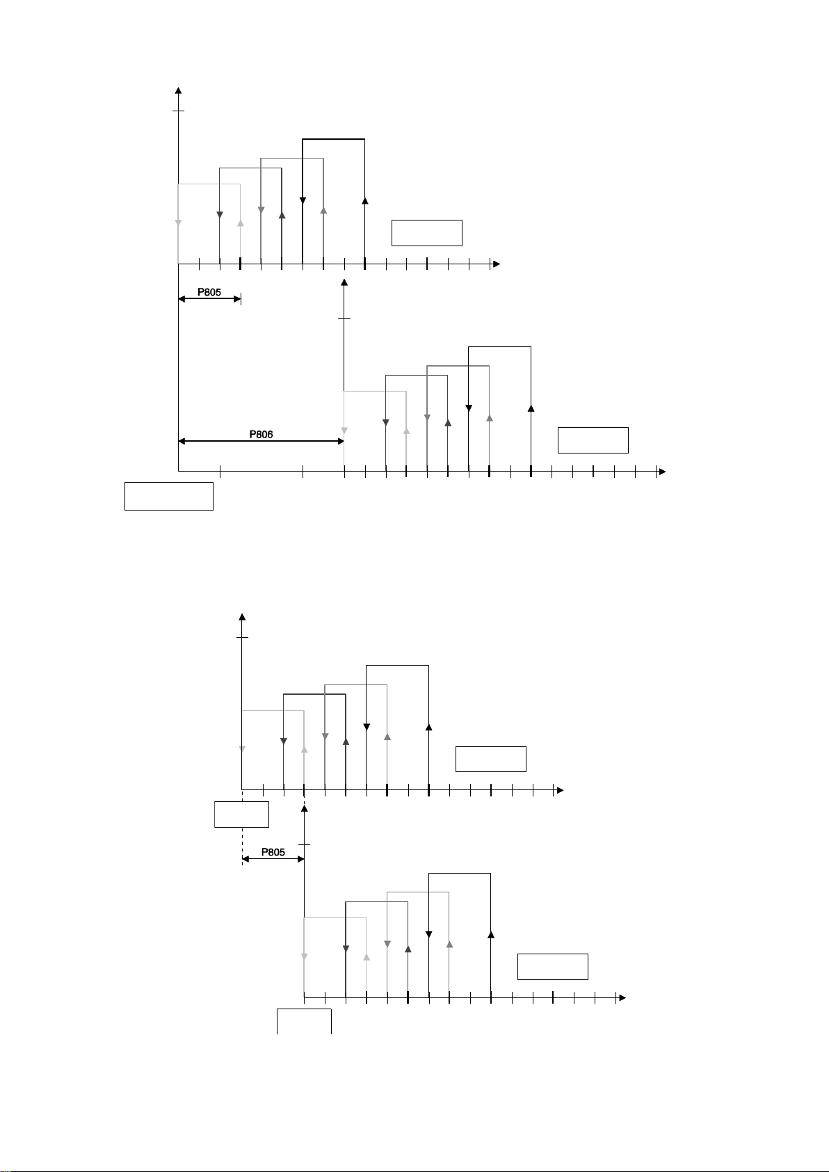
A) Cascade control:
Machine 1
Stage 1
Machine 2
Stage 2
Machine 1
stage
Machine 2
stage
Machine 1
STP
Machine 2
STP
Master machine
STP
Note: P804 = Cascade → parameter P143 on each machine becomes equal to 1°C. This is because the interstage differential on each
machine will be adjusted by the value of P143 on each machine.
Machine 2‟s setpoint is shifted by P806 relative to machine 1‟s setpoint. The value of P806 will have to be selected based on machine 1 in
order to achieve an operating order similar to the start-up of the last stage (see figure above).{
B) Control in parallel with "shifted setpoint":
Machine 1 adjusts itself to the master machine‟s setpoint. Machine 2‟s setpoint is shifted by the value of P805. Thus, the machine 2‟s setpoint
2 is machine 1‟s setpoint + P805.
88
Page 91
C) Water return control for storage (P154 on master machine = Yes):
M A S T E R S L A V E C T R L
M A S T E R M A C H I N E
S L A V E M A C H I N E
10- E L E C E X P . V A L V E
P 6 0 1 C I R C U I T 1
V A L V E T Y P E E X 4
P 6 0 2 C I R C U I T 1
S U P E R H E A T S T P 6 ° C
P 6 0 3 C I R C U I T 1
M O P P O I N T Y E S
P 6 0 4 C I R C U I T 1
MOP V A L U E 1 5 ° C
P 6 0 5 O P N G C 1 E X V
S T A R T A I R C O N X X X %
P 6 0 6 O P N G C 1 E X V
S T A R T H E A T P U M P X X X %
P 6 0 7 P 6 0 7 O P E N I N G T I M E
S T A R T - U P C I R C U I T 1 X X S
P 6 0 8 S L O W M O D E
C I R C U I T 1 E X V N O
P 6 1 1 C I R C U I T 2
V A L V E T Y P E EX4
This type of control makes it possible to generate maximum capacity at a given time, often when electricity is cheapest. Both machines are
turned on at an interstage time delay of 10 seconds when P122 + P155 is achieved. The machines are shut off at P122 at an interstage time
delay of 1 second.
- If P154 = Yes, storage control is enabled and the control mode based on the selected setpoint is controlled by the master machine.
Cascade control is used by default for both machines when setpoint 1 selected (standard control).
The „Yes‟ value of P154 on the slave machine becomes inaccessible if P28 = Yes.
D) Hourly scheduling:
If P27 = Yes, the hourly schedules of two parallel-connected machines will be controlled by the control parameters on the master machine and
the hourly schedule on the slave machine will become inaccessible.
22.1.5 Machine status menu:
If there are no general faults and the automatic operation inputs are closed, a submenu (overrides the fault message) is added to the machine
status menu:
23 ACTUATION OF THE ELECTRONIC EXPANSION VALVEE
23.1 With Alco driver and display
Only fault feedback signals from the valve are managed in this case
23.2 With CIAT driver
This configuration corresponds to using the electronic expansion valve with the CIAT expansion board and on which the Alco EXV miniboard
with the software is connected.
When P42 is set to this value, the control and view parameters for the Alco electronic expansion valve can be accessed.
The compressor on/off signals authorising the expansion valve to move, as well as the low temperature and suction temperature signals, will
be transmitted over a bus link.
23.2.1 Menus if P42 = CIAT:
Main menu:
Electronic expansion
valve configuration menu:
89
Page 92
P 6 1 2 C I R C U I T 2
S U P E R H E A T S T P 6 ° C
P 6 1 3 C I R C U I T 2
M O P P O I N T Y E S
P 6 1 4 C I R C U I T 2
MOP V A L U E 1 5 ° C
P 6 1 5 O P N G C 2 E X V
S T A R T A I R C O N X X X %
P 6 1 6 O P N G C 2 E X V
S T A R T H E A T P U M P X X X %
P 6 1 7 O P E N I N G T I M E
S T A R T C 2 X X S
P 6 1 8 C I R C U I T 2
S L O W M O D E NO
P 3 2 5 C 1 E X V
O P E N I N G X X X %
P 3 5 5 C 2 E X V
O P E N I N G X X X %
P 5 5 8 C I R 1 E X V V E R S I O N
N O . X X . Y Y V C M X X . Y Y
P 5 5 9 C I R 2 E X V V E R S I O N
N O . X X . Y Y V C M X X . Y Y
E X V T E S T . 1
E X V T E S T . 2
E X V T E S T C X
A U T O
Parameters P608 and P618 are visible only if P2 ≠ reversible air-to-water
Operation parameters:
23.2.2 Manual EXPANSION VALVE MODE if P42 = CIAT:
If Test Mode is set to „Yes‟ it retains all standard testing functionalities and provides access to the manual override menu for the electronic
expansion valves when – is pressed.
Manual override of expansion valves (opening and closing)
If P3 = 1, access to EXV TEST.1 mode only.
Press + and – to change expansion valves.
Display:
When either test mode is confirmed (OK ), access is to the settings menu is provided.
Display:
The expansion valve remains in automatic mode the entire time AUTO is displayed. To enter settings mode, press OK.
- To send a signal to open the valve, press + → The percentage immediately higher than the percentage of opening requested by the
controller will appear.
- To send a signal to close the valve, press – → The percentage immediately lower than the percentage of opening requested by the
controller will appear.
To adjust the valve‟s percentage of opening to the desired value, press + and – . This percentage can be changed in increments of 1%.
90
Page 93
Display:
E X V T E S T C X
O P E N I N G X X X %
U N I T Δ P b a r L I M I T
O P T I M I S E D O P E R A T I O N
C P D E L T A P L I M I T
P W R R E D U C T I O N x x m n
F A U L T D E L T A P x x m n
x C U T ( S ) I N 2 4 H
To exit manual mode, press Reset.
The expansion valve will automatically return to automatic mode if no buttons are pressed on the console for 15 minutes.
23.2.3 Control of electronic expansion valve at start-up if P42 = CIAT:
Comment:
- The expansion valve‟s percentage of opening and slow mode (set to „No‟) are forced when the compressor is turned on.
- The percentage of opening values in air conditioning and heat pump modes as well as the forcing time can be adjusted using their
corresponding parameters.
23.2.4 Control of the LP sensor:
If P42 = CIAT:
- The LP sensor fault has a time delay of 120 seconds at power-up. It is not taken into account when the unit is off or at the end of the
defrosting cycle during pressure balancing.
- The default value of P36 and P38 becomes 17.3 b.
24 IMPORTANT INFORMATION REGARDING THE CONTROL OF AN INVERTER COMPRESSOR
- Parameters P195 (ΔP for power reduction) and P144 (interstage differential) are visible even though there is just one compressor. P144
(interstage differential) has an adjustment range of 0.5 to 10°C.
- Parameters P145, P146, P147 and P148 are hidden if P7 = INVERTER and supply control is selected. On the other hand, when P141 = supply
or return, parameters P143 and P144 remain visible and are set to a default value of 1.5°C.
- Output 3 (stage 2, circuit) on terminal block J3 on the motherboard is used to inform the variable speed drive of any faults requiring the
compressor to be shut off. As a result, the compressor will be shut off if a fault is detected (the contact opens).
- Start-up time delay: P66 (Visible only if P7 = INVERTER. Default value of 120 seconds. Adjustable between 0 to 300 seconds in 30-second
increments).This time delay corresponds to the minimum time allowed for the compressor control voltage to reach its maximum value of 10 V
(value corresponding to the compressor‟s 90 Hz frequency). In other terms, the compressor will not reach 90 Hz until the end of this time delay
even if it is requested to do so by the network‟s heat load.
- Parameter P192 (maximum fan speed threshold) becomes visible. Its default value is 8.0 V.
- The order in which the compressors turn on and off will be given via output 2 on terminal block J3 on the motherboard (stage 1, circuit 1).
- The compressor speed will be adjusted by an 0-10 V modulating signal (output 2-3 on terminal block J2 on the motherboard).
The following protections are enabled only if P7 = INVERTER:
These limitations are due to the compressor technology.
A) If the evaporating temperature drops to or below -20°C for 1 minute:
The minimum frequency in both heating mode and cooling mode becomes 50 Hz until the evaporating temperature rises to or above -15°C for
1 minute.
B) If the condensing temperature rises to or above 60°C for 1 minute:
The minimum frequency in both heating mode and cooling mode becomes 50 Hz until the condensing temperature rises to or above 58°C for
1 minute.
C) Maximum pressure difference:
- During water heating:
If HP ≥ 4 × LP + 13.5, 120 after start-up, CONNECT 2 adjusts the control setpoint so as not to push the compressors near their limits too often.
If necessary, a coil defrosting cycle will be forced on.
Information message:
- During water chilling:
If HP ≥ 4 × LP + 13.6, the unit reduces its power by either reducing the compressor speed to 50 Hz or by turning off the compressor.
Information message:
Fault function: (enabled in cooling mode and heating mode)
Operation:
The max. Δp threshold is set at HP 4 × BP + 15.6
If this fault causes at least 5 shutdowns in 24 hours:
- Corresponding circuit shut off.
- 30 min. time delay (in seconds in test mode)
- Fault output off
- Circuit fault LED on console flashes.
91
Page 94
If this fault causes more than 5 shutdowns in 24 hours:
C I R C U I T x O F F
C P D E L T A P F A U L T
M A C H I N E O F F
O U T T E M P . T O O L O W
C I R C U I T x
B E I N G D E F R O S T E D
C I R C U I T x O F F
D E F R O S T I N G I M P O S S I B L E
W A T E R T E M P . R I S I N G
F O R D E F R O S T I N G
- Corresponding circuit shut off.
- Fault output on
D) Compressor driver fault:
Terminals 2-3 on terminal bloc J5 on the CONNECT 2 board receive signals indicated faults on the Danfoss compress driver.
Only alarms that shut down the compressor are received.
When contact 4-6 on the driver opens, the driver is in alarm mode. The following message should appear on the CONNECT 2 console:
This function is activated 5 seconds after the power is turned on.
- Compressor shut off
- Fault acknowledged automatically
- Fault stored in memory in case of a mains power failure
- Fault saved in fault memory
- Circuit fault LED on console lit steady.
- Relay in On position
- Compressor driver fault relay on relay board in On position
- General fault LED lit steady
25 DEFROSTING OF THE EVAPORATOR COILS
CIAT has developed an optimised frosting control system.
Called DEGIPAC (P159 = optimised), it defrosts the evaporator
coils only when frost has actually formed on them instead
of based on the frosting time (P159 = fixed). It does so by
continuously monitoring the difference in temperature between
the coil and the outdoor air. If this difference is abnormally high, it
turns on the defrost cycle. DEGIPAC makes it possible to
- Defrost cycle for reversible machines with split circuits (where
P2 = 3 and P11 = split)
The defrost cycle is turned on when any of the following occur:
The discharge temperature is too high (see discharge protection
in heating mode);
Ice is detected on the coil by the sensors on the coils. In this
case, defrosting is performed by only one circuit at a time to
ensure a minimum supply of hot water for the system;
A difference in pressure, where HP > LP +13.5 for 120 seconds if
INVERTER compressors are used.
- If this temperature is too low (< P52 + 8 K if there are 2 compressors per circuit and < P52+16 K if there is 1 compressor per circuit) and
there is no way to increase it, the unit will shut off, save the fault in memory, and display the following message:
- If the temperature can be raised via the second circuit, a boiler or electric auxiliary heaters, the following message will appear:
- If this temperature exceeds 26°C, the circuit rises to maximum
temperature before the four-way valve reverses and stays at
maximum temperature during defrosting in order to minimise the
defrosting time.
Note: During the defrost cycle, CONNECT 2 continuously monitors the temperatures and pressures to prevent frost from forming on the heat
exchanger and thus turning on the protections.
This is why the fans may turn on during a defrost cycle.
continue producing hot water for hours during cold, dry weather
without having to defrost the coils. As a result, it improves the
seasonal COP.
Parameter P161 is used to advance (if P161 < default value) or
delay (if P161 > default value) the start of the defrost cycle.
- Defrost cycle for reversible machines with intertwined or mixed
circuits (where P2 = reversible air-to-water and P11 = intertwined
or mixed). In this case, defrosting is performed by both circuits at
the same time.
Defrosting is possible only when the water return temperature is
high enough to ensure that the heat exchanger will not freeze
when the cycle is reversed.
Defrosting is triggered by the low-pressure sensor that reads the
lowest value.
- If this temperature drops below 26°C, the circuit rises to
maximum temperature before the four-way valve reverses and
lowers in temperature during defrosting to prevent frost from
forming on the heat exchanger.
26 HOURLY PROGRAMMING
26.1 Presentation
This function allows the weekly management of liquid chillers by selecting:
- 6 programming stages (maxi).
- 6 holidays zones (maxi).
92
Page 95
26.2 Definition of the programming stages
Type of programme
Status before starting time
Status before starting time
and ending time
Status after ending time
CSG1 -stop
Stop
Running on setting 1
Stop
CSG2 -stop
Stop
Running on setting 2
Stop
CSG1-CSG2
Running on setting 2
Running on setting 1
Running on setting 2
CSG2-CSG1
Running on setting 1
Running on setting 2
Running on setting 1
T I M E P R O G R A M M I N G O N
9 - P R O G R A M M I N G
T I M E T A B L E
D A Y S O F F
T I M E T A B L E N ° x ↑
↓
2nd line display:
type of regulation
N° of selected spacing,
from 1 to 6
Setting:
Starting time
Ending time
Selected days (M.T.W.T.F.S.S.)
Type of regulation: Setting 1 – Stop/Setting 2 – Stop/setting 1 – setting 2 / setting 2 – setting 1/non valid.
Setting by fault:
Starting hour: 0h00
Ending hour: 0h00
Validated days: none
Type of regulation not validated.
26.3 Definition of holiday zones
Settings:
Type of zone: non valid, stop, running on setting 1, running on setting 2.
Starting date dd-mm
Ending date dd-mm
Setting by fault Non valid, from 01-01 to 01-01
26.4 Operation
When putting under voltage or when setting the time, the information on the machine status are updated as a function of the programming settings.
The user can change the status of his unit (Run/Stop – ½ setting regulation) but if a time range or a holiday zone is active, the information will
be updated at the starting or ending time of the programming
In the case where at least one time range or one holiday zone is validated, the parameter P120 is forced on « 2 per console or BMS » and
cannot be modified.
When going under test mode, the programming becomes non active. When leaving the test mode, the unit status information are updated as a
function of the programming settings.
In case of range overlapping, the running mode has priority over the stop mode and setting 1 over setting 2.
Same thing in case of overlapping of zones.
If a programme stage is active (# non validated) and the real day is selected, the status of the unit is as follows:
If at least one time range or one holiday zone is validated, alternate the message machine stopped or setting/temp with a message
in order to signal to the user that the status will be updated on next status change of time range. Display of each of these messages
for 3 seconds.
Message to be displayed:
Access principle:
Through menu 9: "9 PROGRAMMING"
-If validated by key "ENTER", 2 sub-menus "HOURLY PROGRAMMING" and "HOLIDAY ZONES" appear.
Through keys + and – , select one of the 2 sub- menus, then validate with "ENTER"
Position of the cursor:
When surfing in the various menus, the cursor is located at the top, on the left.
For modifying the settings, it is located at the bottom right side, last but one character.
- When entering the « TIME RANGE » menu "
Display:
Unroll the time range with key + or – then validate with key "ENTER"
Once the time range has been selected, the regulation type has to be chosen..
By pressing "Enter", we have access to the setting. By pressing key + or –, the following menus appear. For validation,
press "Enter".
93
Page 96
T Y P E OF C ONT R O L ↑
S E T P O I N T 1 – O F F ↓
T Y P E O F C O N T R O L ↑
S E T P O I N T 2 – O F F ↓
T Y P E O F C O N T R O L ↑
S E T P . 1 - S E T P . 2 ↓
T Y P E O F C O N T R O L ↑
S E T P . 2 - SET P . 1 ↓
T Y P E O F C O N T R O L ↑
N O V A L I D ↓
S E L E C T D A Y S ↑
M T W T F S S ↓
S T A R T O F T I M E y y H x x ↑
E N D O F T I M E y y H x x ↓
D A Y S O F F N ° x ↑
↓
T Y P E OF Z O N E ↑
N O V A L I D ↓
T Y P E OF Z O N E ↑
O F F ↓
T Y P E OF Z O N E ↑
S E T P O I N T 1 ↓
T Y P E OF Z O N E ↑
S E T P O I N T 2 ↓
D A T E OF S T A R T DD/ M M ↑
D A T E OF E N D DD/ M M ↓
Display 2nd line:
zone type
N° of zone selected,
from 1 to 6
Once the regulation has been validated, « days selected » appears
By pressing Enter, days are selected: key "+" to validate the day – key "–" to remove the validation.
Set in this order the starting hour/starting minute/ending hour/ending minute.
By pressing "ENTER", set hours, then minutes.
Any modification leads to the updating of the unit status.
Any type of setting is possible (starting time < ending time, starting time = ending time, starting time > ending time)
If the ending time ≤ starting time, the programme is considered to be ending on the following day.
If one enters in the menu "HOLIDAY ZONES"
Display:
Select the n° of the holiday zone to be set by pressing key "ENTER".
Setting text:
Starting day and ending day
Set in the following order:
Starting day /starting month /ending day /ending month.
All types of settings are possible (starting day < ending day, starting day = ending day, starting day > ending day)
If the ending day < starting day, the programme is considered to be ending the year after.
Operation of holiday zones:
If a holiday zone is active (starting date ≤ present date ≤ ending date), the time ranges become non active.
The unit operating status becomes the one of the active zone (stop, running on setting 1 or running on setting 2).
At the end of the holiday zone, if no time zone is validated, the operation is the one existing at the start of the holiday zone
94
Page 97
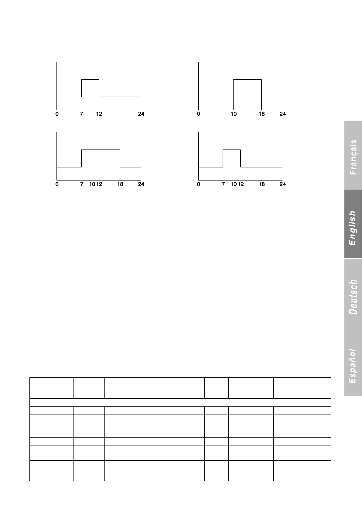
Example:
Register No.
hexadecimal
Register
No.
decimal
Description
Format
Type
Registers accessible in read-only mode (Functions 3 or 4)
0x01
1
Controller name
Decimal
Read-only
33 = CONNECT 2
0x02
2
Actual operating mode
Decimal
Read-only
0x3 and 0x4
3 and 4
Outdoor temperature
Float
Read-only
0x5 and 0x6
5 and 6
Control setpoint
Float
Read-only
0x7 and 0x8
7 and 8
Evaporator inlet temperature
Float
Read-only
0x9 and 0xa
9 and 10
Evaporator outlet temperature
Float
Read-only
0xb and 0xc
11 and 12
Condenser temperature
Float
Read-only
0x13
19
Number of stages on
Char
Read-only
Available with versions
09.00 and higher
0x20 and 0x21
32 and 33
P285 Heating mode runtime (in hours)
Float
Read-only
Prog 1: 7-12h CSG1-CSG2 MTW TF
Prog 2: 10-18h CSG1-stop MT TF
Holiday zone: 10-08 / 30-08 : stop
Prog 1: MTWTF Prog 2: MTWTF
Setting 1 Setting 1
Setting 2 Setting 2
Result:
Status: MTWTF Status: MTWTF
Setting 1 Setting 1
Setting 2 Setting 2
Saturday and Sunday not being selected in the hourly programming, the unit is therefore stopped.
The unit is stopped between 10th August and 30th August, this period being selected as holiday zone.
27 COMMUNICATION PROTOCOL
A) Communication medium
- RS485
3-pin connector on terminal 1 of terminal block J11: A or +
Terminal 2: B or –
Terminal 3: connected to earth
for shielding if desired
Two lights provide information on the status of the transmission
(see Section 3.1, control board)
- D50 → Receive LED. Usually off; flashes when a message is
received by the board.
If this light remains on, the bus is reversed. Swap terminals 1 and
2 on J11.
- D52 → Send LED. Usually off; lights up when the CPU sends a
message over the bus.
B) Transmission mode
Serial, asynchronous, half duplex, RTU mode.
- 1 start bit,
- 8 data bits,
- The parity is set via parameter P702,
The number of stop bits is set via parameter P703,
- The transmission speed is set via parameter P701,
- The unit number on the bus is set via parameter P705.
27.1 Registers accessible by customer
Coding of analogue values
Standard 32-bit IEEE format (2 registers).
Order of values:
- If P704 = No → low order, high order.
- Si P704 = Yes → high order, low order.
Function codes used.
1 or 2: read n bits
3 or 4: read multiple registers (16 bits)
5: write one bit …………..
6: write register function………
8: read diagnostics counters
11: read event counter
15: write n bits
16: write multiple registers (16 bits)
Note: the write functions are enabled if parameter P103 is set to
"Remote, BMS…"
Error codes:
1: function code unknown
2: address incorrect
3: data error
95
Page 98
Register No.
hexadecimal
Register
No.
decimal
Description
Format
Type
Registers accessible in read-only mode (Functions 3 or 4) CONTINUED
0x22 and 0x23
34 and 35
P286 Cooling mode runtime (in hours)
Float
Read-only
0x24 and 0x25
36 and 37
P287 Pump 1 runtime (in hours)
Float
Read-only
0x26 and 0x27
38 and 39
P288 Pump 2 runtime (in hours)
Float
Read-only
0x28 and 0x29
40 and 41
P310 Number of starts, stage 1, circuit 1
Float
Read-only
0x2a and 0x2b
42 and 43
P311 Stage 1, circuit 1 runtime
Float
Read-only
0x2c and 0x2d
44 and 45
P313 Number of starts, stage 2, circuit 1
Float
Read-only
0x2e and 0x2f
46 and 47
P314 Stage 2, circuit 1 runtime
Float
Read-only
0x30 and 0x31
48 and 49
P340 Number of starts, stage 1, circuit 2
Float
Read-only
0x32 and 0x33
50 and 51
P341 Stage 1, circuit 2 runtime
Float
Read-only
0x34 and 0x35
52 and 53
P343 Number of starts, stage 2, circuit 2
Float
Read-only
0x36 and 0x37
54 and 55
P344 Stage 2, circuit 2 runtime
Float
Read-only
Registers accessible in read mode (Functions 3 or 4) and write mode (Function 16)
0x101 and 0x102
257 and 258
P121 Cooling setpoint 1
Float
Read/Write
0x103 and 0x104
259 and 260
P122 Cooling setpoint 2
Float
Read/Write
0x105 and 0x106
261 and 262
P123 Heating setpoint 1
Float
Read/Write
0x107 and 0x108
263 and 264
P124 Heating setpoint 2
Float
Read/Write
0x109 and 0x10a
265 and 266
P125.1 Setpoint for 4 mA in cooling mode
Float
Read/Write
0x10b and 0x10c
267 and 268
P125.2 Setpoint for 4 mA in heating mode
Float
Read/Write
0x10d and 0x10e
269 and 270
P126.1 Setpoint for 20 mA in cooling mode
Float
Read/Write
0x10f and 0x110
271 and 272
P126.2 Setpoint for 20 mA in heating mode
Float
Read/Write
Registers accessible in read mode (Functions 3 or 4) and write mode (Functions 6 or 16)
0x200
512
Year
Decimal
Read/Write
0 to 99
0x201
513
Month
Decimal
Read/Write
1 to 12
0x202
514
Day of the month
Decimal
Read/Write
1 to 31
0x203
515
Day of the week
Decimal
Read/Write
1 to 7 (1: Monday, 2:
Tuesday, etc.)
0x204
516
Hours
Decimal
Read/Write
0 to 23
0x205
517
Minutes
Decimal
Read/Write
0 to 59
Hexadecimal bit
No.
Bit No.
decimal
Description
Type
Read-only bit (functions 1 or 2)
0x01
1
P103 Control type
Read-only
0: Local, 1: Remote
0x02
2
Operating summary (On/Off and automatic operation
input closed)
Read-only
1 = On
0x03
3
State of pump 1 output
Read-only
1 = On
0x04
4
State of pump 2 output
Read-only
1 = On
0x05
5
Output state, stage 1, circuit 1
Read-only
1 = on
0x06
6
Output state, stage 2, circuit 1
Read-only
1 = On
0x07
7
Output state, stage 1, circuit 2
Read-only
1 = On
0x08
8
Output state, stage 2, circuit 2
Read-only
1 = On
0x09
9
State of auxiliary electric heater 1 or boiler
Read-only
1 = On
0x0a
10
State of auxiliary electric heater 2
Read-only
1 = On
0x0b
11
State of auxiliary electric heater 3
Read-only
1 = On
0x0c
12
State of auxiliary electric heater 4
Read-only
1 = On
0x0d to 0x0f reserved
0x10
16
General fault summary (1 fault below present)
Read-only
1 = Fault
0x11
17
Phase controller fault
Read-only
1 = Fault
0x12
18
Water flow fault
Read-only
1 = Fault
0x13
19
Pump 1 fault
0x14
20
Pump 2 fault
Read-only
1 = Fault
27.2 Customer access bits
96
Page 99
Hexadecimal bit
No.
Bit No.
decimal
Description
Type
0x0d to 0x0f reserved (continued)
0x15
21
Pump fault, 1 loop
Read-only
1 = Fault
0x16
22
Pump fault, 2 loops
Read-only
1 = Fault
0x17
23
Heat exchanger inlet sensor fault
Read-only
1 = Fault
0x18
24
Heat exchanger outlet sensor fault
Read-only
1 = Fault
0x19
25
Outdoor temperature sensor fault
Read-only
1 = Fault
0x1a
26
Condenser sensor fault
Read-only
1 = Fault
0x1b
27
Manifold outlet sensor fault
Read-only
1 = Fault
0x1c
28
Fan fault
Read-only
1 = Fault
0x1d
29
EEPROM FAULT
Read-only
1 = Fault
0x1e
30
Loop inlet sensor fault (MULTICONNECT)
Read-only
1 = Fault
0x1f
31
Loop outlet sensor fault (MULTICONNECT)
Read-only
1 = Fault
0x20
32
AEROCONNECT link fault
Read-only
1 = Fault
0x21
33
Outdoor temperature too high in cooling mode
Read-only
1 = Fault
0x22
34
Change of operating mode fault
Read-only
1 = Fault
0x23
35
Winter protection
Read-only
1 = Fault
0x24
36
Exchanger ambient sensor fault
Read-only
1 = Fault
0x25 to 0x3f reserved
0x40
64
Circuit 1 fault summary
Read-only
1 = Fault
0x41
65
Stage 1, circuit 1 fault
Read-only
1 = Fault
0x42
66
Stage 2, circuit 1 fault
Read-only
1 = Fault
0x43
67
Manual HP fault, circuit 1
Read-only
1 = Fault
0x44
68
HP fault, circuit 1 pressure sensor
Read-only
1 = Fault
0x45
69
Circuit 1 LP fault
Read-only
1 = Fault
0x46
70
Water frosting fault, circuit 1
Read-only
1 = Fault
0x47
71
Refrigerant frosting fault, circuit 1
Read-only
1 = Fault
0x48
72
Exchanger frosting fault, circuit 1
Read-only
1 = Fault
0x49
73
Discharge fault, stage 1, circuit 1
Read-only
1 = Fault
0x4a
74
Discharge fault, stage 2, circuit 1
Read-only
1 = Fault
0x4b
75
Defrosting fault, circuit 1
Read-only
1 = Fault
0x4c
76
Expansion valve fault, circuit 1
Read-only
1 = Fault
0x4d
77
Stepper motor fault, circuit 1 expansion valve
Read-only
1 = Fault
0x4e
78
Low superheat fault, circuit 1
Read-only
1 = Fault
0x4f
79
High superheat fault, circuit 1
Read-only
1 = Fault
0x50
80
VCM module fault, expansion valve 1
Read-only
1 = Fault
0x51
81
Exchanger outlet sensor fault, circuit 1
Read-only
1 = Fault
0x52
82
Exchanger freon sensor fault, circuit 1
Read-only
1 = Fault
0x53
83
Sensor fault, coil A, circuit 1
Read-only
1 = Fault
0x54
84
Sensor fault, coil B, circuit 1
Read-only
1 = Fault
0x55
85
Sensor fault, coil C, circuit 1
Read-only
1 = Fault
0x56
86
Sensor fault, coil D, circuit 1
Read-only
1 = Fault
0x57
87
Discharge sensor fault, stage 1, circuit 1
Read-only
1 = Fault
0x58
88
Discharge sensor fault, stage 2, circuit 1
Read-only
1 = Fault
0x59
89
Circuit 1 HP sensor fault
Read-only
1 = Fault
0x5a
90
Circuit 1 LP sensor fault
Read-only
1 = Fault
0x5b
91
Circuit 1 suction sensor fault
Read-only
1 = Fault
0x5c
92
Circuit 1 liquid sensor fault
Read-only
1 = Fault
0x5d
93
Circuit 1 exp. valve board link fault
Read-only
1 = Fault
0x5e
94
Link fault, additional board for reversible
Read-only
1 = Fault
0x5f
95
Tsat discharge fault, Inverter compressor
Read-only
1 = Fault
0x60
96
Mechanical fault, Inverter compressor
Read-only
1 = Fault
0x61 to 0x7f reserved
0x80
128
Load shedding, stage 1, circuit 1
Read-only
1 = Load shedding
0x81
129
Load shedding, stage 2, circuit 1
Read-only
1 = Load shedding
97
Page 100
Hexadecimal
bit No.
Bit No.
decimal
Description
Type
0x82 to 0x9f reserved
0x100
256
Circuit 2 fault summary
Read-only
1 = Fault
0x101
257
Stage 1, circuit 2 fault
Read-only
1 = Fault
0x102
258
Stage 2, circuit 2 fault
Read-only
1 = Fault
0x103
259
Manual HP fault, circuit 2
Read-only
1 = Fault
0x104
260
HP fault, circuit 2 pressure sensor
Read-only
1 = Fault
0x105
261
Circuit 2 LP fault
Read-only
1 = Fault
0x106
262
Water frosting fault, circuit 2
Read-only
1 = Fault
0x107
263
Refrigerant frosting fault, circuit 2
Read-only
1 = Fault
0x108
264
Exchanger frosting fault, circuit 2
Read-only
1 = Fault
0x109
265
Discharge fault, stage 1, circuit 2
Read-only
1 = Fault
0x10a
266
Discharge fault, stage 2, circuit 2
Read-only
1 = Fault
0x10b
267
Defrosting fault, circuit 2
Read-only
1 = Fault
0x10c
268
Expansion valve fault, circuit 2
Read-only
1 = Fault
0x10d
269
Stepper motor fault, circuit 2 expansion valve
Read-only
1 = Fault
0x10e
270
Low superheat fault, circuit 2
Read-only
1 = Fault
0x10f
271
High superheat fault, circuit 2
Read-only
1 = Fault
0x110
272
VCM module fault, expansion valve 2
Read-only
1 = Fault
0x111
273
Exchanger outlet sensor fault, circuit 2
Read-only
1 = Fault
0x112
274
Exchanger freon sensor fault, circuit 2
Read-only
1 = Fault
0x113
275
Sensor fault, coil A, circuit 2
Read-only
1 = Fault
0x114
276
Sensor fault, coil B, circuit 2
Read-only
1 = Fault
0x115
277
Sensor fault, coil C, circuit 2
Read-only
1 = Fault
0x116
278
Sensor fault, coil D, circuit 2
Read-only
1 = Fault
0x117
279
Stage 1, circuit 2 discharge sensor fault
Read-only
1 = Fault
0x118
280
Stage 2, circuit 2 discharge sensor fault
Read-only
1 = Fault
0x119
281
Circuit 2 HP sensor fault
Read-only
1 = Fault
0x11a
282
Circuit 2 LP sensor fault
Read-only
1 = Fault
0x11b
283
Circuit 2 suction sensor fault
Read-only
1 = Fault
0x11c
284
Circuit 2 liquid sensor fault
Read-only
1 = Fault
0x11d
285
Circuit 2 exp. valve board link fault
Read-only
1 = Fault
0x11e
286
Link fault, additional board for reversible
Read-only
1 = Fault
0x11f to 0x13f reserved
0x140
320
Load shedding, stage 1, circuit 2
Read-only
1 = Load shedding
0x141
321
Load shedding, stage 2, circuit 2
Read-only
1 = Load shedding
Read (Functions 1 or 2) and write (Functions 5 or 15) bit
0x200
512
On/Off
Read/Write
1 = On
0x201
513
Control set to setpoint 1 or 2
Read/Write
1 = Control set to setpoint 2
0x202
514
Heating or cooling operation
Read/Write
1 = Heating
0x203
515
Load shedding via Modbus, stage 1, circuit 1 (different from 0 x 140)
Read/Write
1 = Off
0x204
516
Load shedding via Modbus, stage 2, circuit 1
Read/Write
1 = Off
0x205
517
Load shedding via Modbus, stage 1, circuit 2
Read/Write
1 = Off
0x206
518
Load shedding via Modbus, stage 2, circuit 2
Read/Write
1 = Off
Read bit (Functions 1 or 2) → Available with versions 09.00 and higher
0x220
544
On/Off summary (1 = keypad on/off = 1 and all automaic
operation controls closed and no oil warm-up time and no
faults)
Read-only
0x221
545
1 = Cooling possible
Read-only
0x222
546
1 = Heating possible
Read-only
0x223
547
1 = 1 stage on
Read-only
0x224
548
1 = Maximum available power reached
Read-only
0x225
549
1 = A major fault preventing output has occurred
Read-only
0x226
550
1 = A reset fault has occurred but output is possible
Read-only
0x227
551
1 = A fault requiring servicing has occurred
Read-only
98
 Loading...