

CIAT condenciat CD Instruction Manual

Instruction manual
condenciat CD
01 - 2015
NA 06.130 C

EN
EN - 1 NA 06.130 C
CONTENTS PAGE
1 - INTRODUCTION 2
2 - RECEIPT OF THE UNIT 2
3 - WARRANTY 2
4 - SAFETY INSTRUCTIONS 2
5 - UNIT LOCATION 2
6 - HANDLING AND POSITIONING 3
7 - INSTALLATION 4
8 - VIBRATION ISOLATORS
(supplied as standard) 4
9 - FLOOR MOUNTING 5
10 - REFRIGERANT CONNECTIONS 6
11 - ELECTRICAL CONNECTIONS 6
12 - CONTROL 7
13 - CONTROL AND SAFETY DEVICES 7
13.1 Low pressure switch 7
13.2 High pressure switch 7
13.3 Internal compressor protection 7
14 - PRE-COMMISSIONING OPERATIONS 7
14.1 Pre-commissioning check 7
15 - COMMISSIONING 8
15.1 Start-up sequence 8
15.2 Check immediately 8
16 - LOCATION OF REFRIGERATING
CIRCUITS AND MAIN COMPONENTS 9
17 - TECHNICAL CHARACTERISTICS 10
18 - SETTING THE CONTROL AND SAFETY
DEVICES 11
19 - ELECTRICAL SPECIFICATIONS 11
20 - CONDENCIAT CD
OPERATING READINGS 12
21 - MAINTENANCE 12
22 - SERVICING 13
22.1 Safety instructions 13
22.2 Noise 13
22.3 Oil 13
22.4 Refrigerants - general information 13
22.5 Halocarbon and
hydrofluorocarbon refrigerants 13
22.6 Weekly checks 14
22.7 Monthly checks 14
22.8 Annual checks 14
23 - TROUBLESHOOTING OPERATING
PROBLEMS 14
23.1 Preliminary advice 14
24 - CUSTOMER CONNECTION OF
REMOTE CONTROL FUNCTIONS 15
24.1 General fault alarm 15
24. 2 Automatic operation control 16
25 - STAGE CONTROL 16
26 - FLUID ELECTRICAL VALVES 17
27 - CONNECTION PRECAUTIONS 17
28 - FAN WIRING 17
29 - ECODESIGN 18
Original text: French Version
NA06.130 C EN - 2
1 - INTRODUCTION
CONDENCIAT CD units are condensation units. They will be connected to a direct expansion coil.
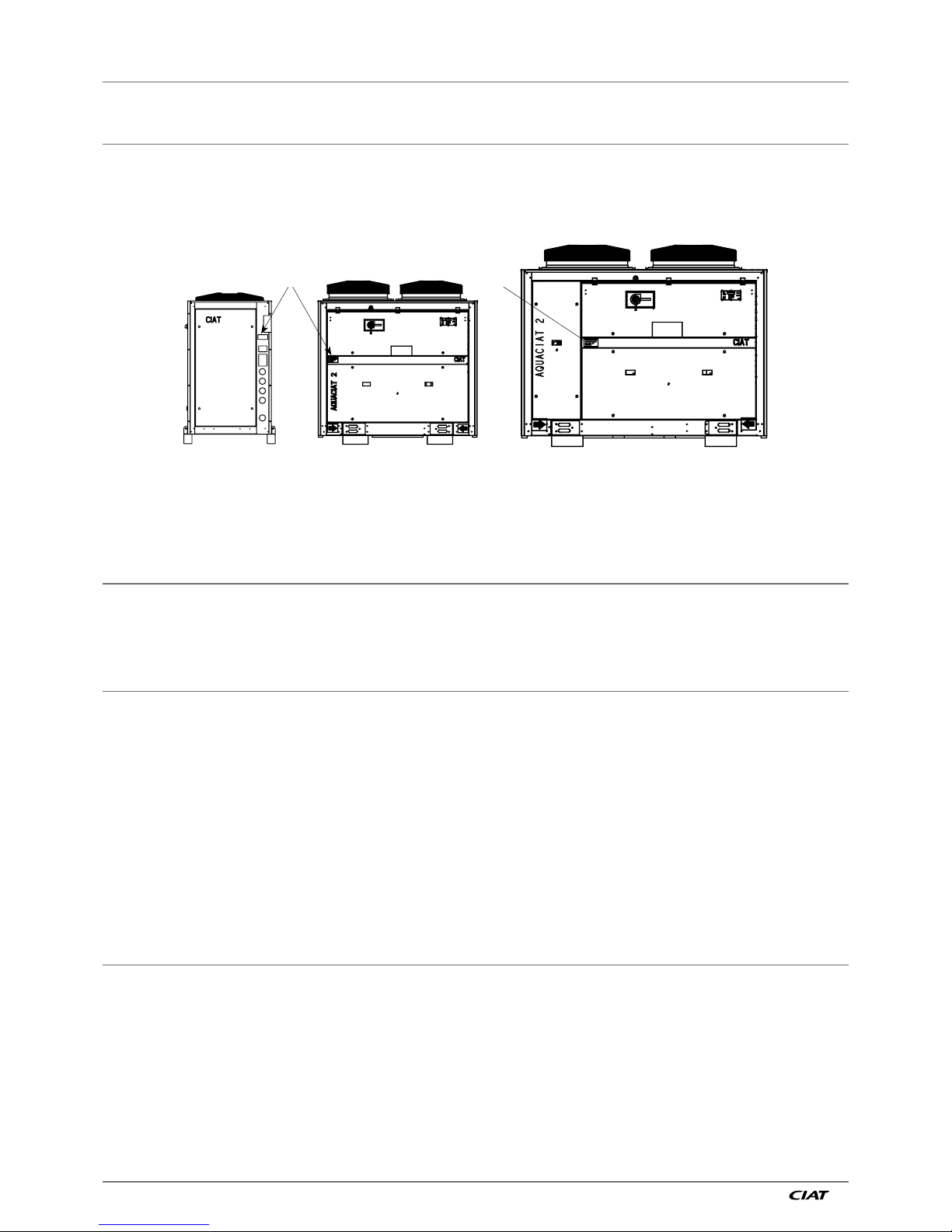
2 - RECEIPT OF THE UNIT
Each unit has a name plate bearing an identication number. Check the name plate on the unit to make sure you have received
the right model. Please include the identication number in all correspondence with CIAT.
100 to 300 350 to 500
350 to 500
A
A
A
= name plate
After unpacking the unit, please inspect it for any damage. If any items are missing or damaged, specify this on the delivery note
and inform the carrier thereof by registered letter within three days of delivery of the unit.
Store at a maximum temperature of 50°C.
3 - WARRANTY
The warranty is effective for a period of 12 months from the date the unit is rst commissioned into service provided said date
occurs within three months of the invoice date.
It is effective for a period of 15 months from the unit invoice date in all other cases.
NOTE: refer to our general terms and conditions of sale for further information.
4 - SAFETY INSTRUCTIONS
To avoid any risk of accident during installation, commissioning and adjustments, the following equipment specicities must be
taken into account:
- Pressurised refrigeration circuits
- Presence of refrigerant
- Presence of electrical voltage
Only experienced and qualied persons may work on such equipment.
The recommendations and instructions in this manual and on each drawing provided with the unit must be followed.
In the case of units with pressure equipment or components, we recommend that you contact your professional organisation for
information on regulations that apply to operators or owners of pressure equipment or components. The specications of this
pressure equipment or these pressure components are given on the name plates or in the regulatory documentation provided
with the product.
A re protection device is tted as standard on all units.
IMPORTANT: Make sure the main disconnect switch in the unit's electrical panel is in the OFF position before working on the unit.
5 - UNIT LOCATION
These units are typically used for refrigeration and are not required to withstand earthquakes. Earthquake resistance has therefore
not been checked.
The tter must check the following points before setting up the unit in its intended location:
- The unit must be installed outdoors
- The surface area of the ground or structure must be strong enough to bear the unit's weight.
- The unit must be perfectly level.
- There must be sufcient clearance around and above the unit to allow servicing and maintenance (see dimensional drawing
provided with unit).
- The room housing the unit must comply with the requirements of regulation EN 378-3 and other specications applicable to the
installation site.
- The intended location must be above ood level.
EN
EN - 3 NA 06.130 C
- Position the unit above the average snow depth in the region where the unit is installed.
- It is strongly recommended to place anti-vibration mounts between the supporting surface and the unit frame and to place
exible couplings on the refrigerant pipes to keep vibrations transmitted by solid materials to a minimum (see section on vibration
dampers).
- Sound level: our units are designed to operate at low noise levels (for this type of equipment).
However, as soon as you begin designing your system, you should take into consideration the outdoor environment to estimate
the radiated noise and the building type to estimate the noise transmitted through the air and by solid materials (vibrations).
Have an analysis carried out by an acoustical engineer.
Important: The ambient temperature must not exceed 50°C during the unit's off cycles.
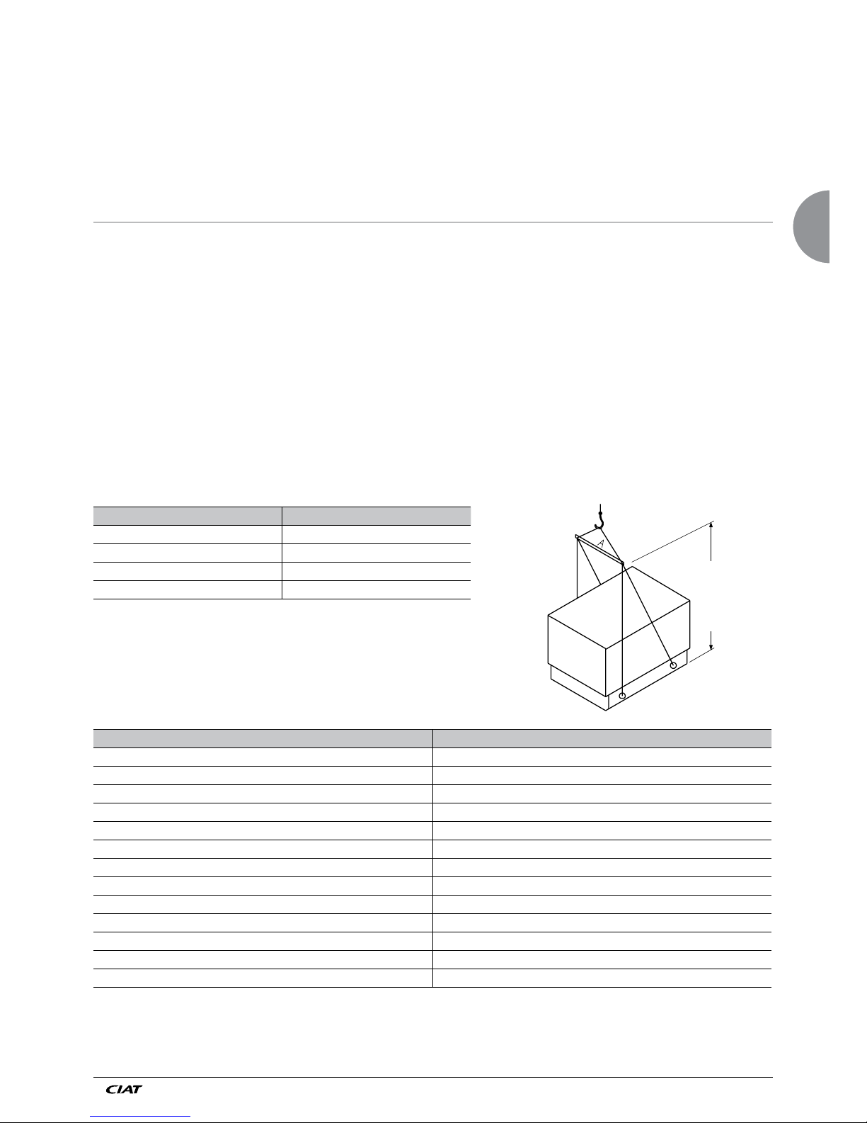
6 - HANDLING AND POSITIONING
To raise the unit, attach the slings to the designated handling holes.
The coordinates of the centre of gravity and the positions of the anchorage points are given on the dimensional drawing.
It is possible to raise the unit with a fork-lift truck provided the necessary precautions are taken to prevent it sliding on the fork-lift
truck's forks.
Warning:
- Only attach the slings to the anchorage points intended for this purpose and which are designated on the unit.
- Use slings with a suitable lifting capacity and follow the lifting instructions on the drawings provided with the unit.
- Warning: the centre of gravity is not necessarily in the middle of the unit and the forces applied to the slings are not always
identical.
- Raise and lower the unit carefully. Take care not to tilt it by more than 15° to avoid any subsequent problems with its operation.
- To avoid damaging the casing, use textile slings with shackles.
- Use a frame with an adjustable centre of gravity to spread the slings away from the top of the unit.
- Always protect the unit casing (panels, uprights, front access door) from damage during handling. Only the frame is designed to
withstand handling.
- Safety during lifting can be ensured only if all these instructions are followed. Failure to do so may result in damage to the
equipment and physical injury.
Sizes A
100 to 150 V 1100
180 to 300 V 1100
350 to 500 V 2242
540 to 700 V 2242
This drawing is provided for information purposes only. Always refer
to the pictograms on the unit and in the documentation
provided with it.
CONDENCIAT CD Empty weight (kg)
100 V 290
120 V 290
150 V 350
180 V 465
200 V 465
240 V 465
300 V 575
350 V 983
400 V 1082
500 V 1090
540 V 1380
600 V 1499
700 V 1676
2500 min.
NA06.130 C EN - 4
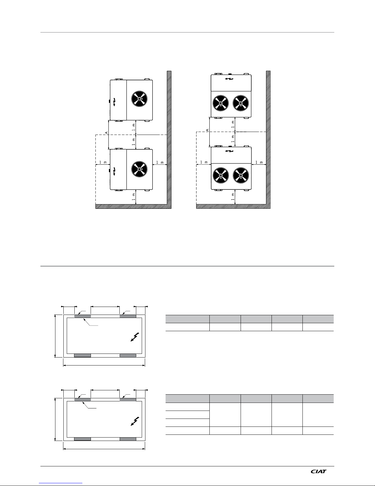
7 - INSTALLATION
(Clearances to be maintained)
It is important for units to be installed with the necessary clearances:
so that air discharged by the condenser is not drawn in through the intake and recirculated.
so that maintenance can be carried out on the unit.
100V to 300V 350V to 700V
2 units: A = 2 m
3 or more units: A = 3 m
For information on the dimensions, weight, anchorage points and centre of gravity, refer to the drawings provided with the unit.
8 - VIBRATION ISOLATORS (supplied as standard)
Anti-vibration mounts must be installed beneath the unit in the case of applications with extremely low vibrations.
The mounts must be placed at the locations illustrated below.
CB
1536
A
DD
1045
P25
Condenciat CD A B C D
100 - 150 250 836 250 50x100
CB
1540
A
DD
1045
P25
Condenciat CD A B C D
180
100 870 330 50x120200
240
300 100 790 350 50x150

EN
EN - 5 NA 06.130 C
375
772
375
DD
2122
2184.5
772
375
375
11921192
D
D
D
2122
2734
P25
P25
Size 350 to 500 V Size 540 to 700 V
CONDENCIAT CD D
350
50x350
400
500
450
600
700
9 - FLOOR MOUNTING
Top view of FRAME Top view of FRAME
Size 100 to 300 V Size 350 to 700 V
Hydraulic
module Size
180 to 300
CD L1 L2 L3 L4
100 - 300 316 316 1540 1044
350 - 500 281 281 2185 2123
540 - 700 405 281 2735 2123
The frame may be bolted to the ground (bolts not supplied by CIAT). The hardness is to be dened depending on the weight and
centre of gravity of the unit.
NA06.130 C EN - 6
10 - REFRIGERANT CONNECTIONS
In order to meet the operating conditions (ow rates, pressure drops), a dimensioning study must be performed.
The diameters of the pipes are not necessarily the same as those of the unit.
Once the unit is tted into place, make the refrigerant connections between the condensation unit and the direct expansion coil.
Take care when routing the pipes. Ensure the shortest distance is used (maximum pipe length 15 metres with maximum change
in level of 6 metres). Strictly observe all the tting instructions. Avoid allowing any contaminants to enter, and carry out all brazing
under a nitrogen purge.
Note:
- Verify the type of refrigerant before working on the refrigerating circuit.
- Only use the uid specied on the name plate.
- Do not use oxygen or air to purge the pipes or pressurise the unit.
- Table of copper piping diameters for a maximum length of 15 m with a maximum change in level of 6 m.
Liquid sight glass
Located on the liquid line just after the dryer, the liquid sight glass is used to monitor the charge in the unit and check for moisture
in the circuit. Bubbles in the sight glass mean that the refrigerant load is insufficient or that the refrigerating circuit contains noncondensable products.
If the sight glass indicator paper changes colour, there is moisture in the circuit.
Warning:
Some of the sight glasses may turn yellow when the machine is powered off as their sensitivity is affected by the fluid temperature.
The sight glasses should return to green after the unit has been operating for a few hours.
If the sight glass remains yellow, there is excessive moisture in the circuit. A specialist intervention is required.
CD
1 circuit 2 circuits
100 120 150 180 200 240 300 350 400 500 540 600 700
Intake pipe 1" 3/8 1" 5/8 2" 1/8 2 x 2" 1/8
Liquid pipes 7/8" 1" 1/8 1" 1/8 2 x 1" 1/8
11 - ELECTRICAL CONNECTIONS
● The units are designed in accordance with the requirements of European standard EN 60204-1.
● They comply with the requirements of the machinery and EMC directives.
● All wiring must be connected in accordance with the regulations that apply to the installation site (e.g. NF C 15100 in
France).
● Always refer to the wiring diagram provided with the unit.
● Follow the power supply specifications indicated on the name plate.
● The voltage must remain within the range indicated:
- Power circuit:
● 400 V (+10 %/-10 %) - 3 ph - 50 Hz + Earth (CD 90 to 700)
Make sure there is no excessive phase shift (<2%) on the supply.
If these conditions are not met, the CIAT warranty will automatically be voided. Please contact your electricity supplier.
● The cable will be carefully determined by the fitter, based on:
- The maximum nominal current (refer to the specifications on page 10)
- The distance between the unit and its power supply.
- The protection to be placed at the power source.
- The neutral operating conditions.
- The electrical connections (refer to the wiring diagram provided with the unit).
- Specifications and regulations applicable at the site.
● The electrical connections are to be made as follows:
- Connection to the power circuit
- Connection of the protective conductor to the earth terminal.
- Connect the general fault alarm potential-free (dry) contact and the automatic operation control (where applicable).
● Connection of external safety devices (compressors slaved to the air handling unit operation) and automatic control (timer
control).
● Connection of the compressor stage control (thermostat or controller, not supplied with the unit).
● Connection of the liquid electromagnetic valve (not supplied).
● The automatic operation control must be connected using a potential-free (dry) contact.
● The power circuit breakers have a standard breaking capacity of 10 KA.
● The unit's power supply is connected on the lower section, on the pipe connection side. The power cables are routed
through an opening.
 Loading...