

CIAT Climaciat Instruction Manual

Instruction manual
CLIMACIAT
®
10 - 2017
EN7486825-02


EN
EN - 1
CONTENTS PAGE
1 - GENERAL INFORMATION 2
1.1 Intended use 2
1.2 Documentation 2
1.3 Warranty 2
2 - SAFETY CONSIDERATIONS 2
3 - REGULATIONS 2
3.1 General information 2
3.2 Applicable standards and directives 3
3.3 Accreditation 3
3.4 Pressure and temperature 3
4 - IDENTIFICATION 3
4.1 Data plate 3
4.2 Pictograms 4
5 - SHIPPING - DELIVERY - HANDLING 5
5.1 Shipping instructions 5
5.2 Container shipping 5
5.3 Delivery 5
5.4 Lifting instructions 5
5.5 Anchoring points for handling 6
5.6 Storage 6
6 - INSTALLATION 6
6.1 Warning 6
6.2 Selecting a location 6
6.3 Assembling the blocks 8
6.4 Adjustable feet and support cylinders 10
6.5 Roof/canopy (Accessories) 11
7 - CONNECTIONS 12
7.1. Condensate drain siphon 12
7.2 Heating/cooling coil 12
7.3 Electric heater 14
7.4 Droplet eliminator 14
7.5 Connecting the fans 15
7.6 Filters 18
7.7 Standalone steam humidifier 18
7.8 Damper and mixing 20
7.9 Heat recovery units 21
8 - CONTROL 22
8.1 AHU with control 22
8.2 AHU without control 22
9 - SYSTEM START-UP 23
9.1 Siphon 23
9.2 Pre-commissioning check 23
9.3 Filters 23
9.4 Fan 24
9.5 Heating and Cooling coils 26
9.6 Electric heater 27
9.7 Steam humidifier 28
9.8 Damper and mixing 28
9.9 Heat recovery unit 28
9.10 Check after start-up 29
10 - OPERATION and MAINTENANCE 30
10.1 General recommendations for cleaning 30
10.2 Filters 30
10.3 Fans 31
10.4 Cooling/heating coil 32
10.5 Electric heater 33
10.6 Steam humidifier 34
10.7 Damper and mixing 34
10.8 Sound attenuator 35
10.9 Heat recovery units 35
10.10 List of checks and maintenance 37
10.11 Specific DIN1946-4 maintenance 38
10.12 Prolonged downtime 38
11 - Special notes for ATEX zones 39
11.1 General information 39
11.2 Marking 39
11.3 System start-up, maintenance 39
11.4 Using tools in an explosive atmosphere 40
11.5 Check - Periodic inspections 41
11.6 Inspection sheet ATEX
42
12 - FINAL SHUTDOWN 43
12.1 Shutting down 43
12.2 Recommendations for disassembly 43
12.3 Materials to be recovered for recycling 43
12.4 Fluids to be recovered for recycling 43
12.5 Waste electrical and electronic
equipment (WEEE) 43
ORIGINAL TEXT: FRENCH VERSION

EN - 2
Thank you for choosing our air handling unit. The design and construction of your unit are the fruit of all the expertise offered
by our company's teams of technicians.
1.1 Intended use
The air handling units are designed for use indoors or outdoors (canopy and roof option mandatory)
The units are intended to provide ventilation and, depending on the composition:
- filtration of normal quality air,
- filtration of air in sterile environments (special version for clean rooms),
- air heating and/or cooling,
- air humidification and/or dehumidification,
- heat evacuation or recovery,
- filtration and handling of particularly moist and/or contaminated air (special versions, e.g. for extracting air from swimming
pools or kitchens),
- or a combination of the above characteristics.
Any use other than that described above is deemed improper.
If necessary, check whether your units are compatible with the applications for which you intend to use them.
The manufacturer is not responsible for damage resulting from improper use.
The user shall be held solely responsible.
Your machine's specific operating conditions are set out in the contract review.
The standard machine is designed to operate in urban and industrial environments with class C3 moderate pollution in
accordance with standard ISO 12944. Other options are available on request for more polluted environments or coastal areas.
WARNING: Take into account the quality of the ambient air and the conditioned air.
1.2 Documentation
This manual contains all of the installation and operating instructions for your unit. This document must be read in full before
carrying out any work on the unit. This manual must be kept in the immediate vicinity of the unit. It does not cover the entire
installation.
Please read all of the documents supplied with your order for information concerning the installation and system start-up
steps.
Depending on the options selected, specific handbooks may be included with this manual, and are also available from your
manufacturer. You should also read these handbooks before installing any options or carrying out any work (e.g. speed
variator, humidifier, control, etc.).
Devices installed and used in ATEX zones are marked with this symbol
. A specific section of this manual is dedicated
to the limits of use and the precautions to be taken when installing, starting up and maintaining these devices. Refer to this
section before installing or carrying out any work.
1.3 Warranty
See general terms and conditions of sale.
Any modification made to the unit by persons other than the manufacturer's employees, or without prior consent, shall result
in cancellation of the warranty.
3.1 General information
Always follow and comply with the instructions in this manual and the regulations and legislation in force in the country of use.
Any modifications or welding to pressurised parts is dangerous and may be prohibited by regulations.
The use of this equipment under seismic loads has not been verified.
1 - GENERAL INFORMATION
2 - SAFETY CONSIDERATIONS
3 - REGULATIONS
The air handling units are designed in compliance with recognised safety rules.
These units must be used in perfect condition and within their field of application.
Only qualified technicians may work on the machine. They must have all the necessary Personal Protective Equipment
(PPE): glasses, gloves, safety shoes, hearing protection, dust mask, etc.
Check the following points before carrying out any work on the air handling unit.
- Cut the main fan power supply. Warning follow the shutdown procedure: A 15-minute fan delay must be applied after the
electric heaters and gas heating systems are shut down to allow complete cooling.
- Equipment lock-out in accordance with standard EN 60204/DIN VDE 0113.
- Warning: depending on the options selected, there may be several different power supplies on the various units (main unit,
supply unit for electric heaters, humidifier). Make sure all power supplies are cut and locked out.
- All moving or rotating parts must be shut down.
- Wait at least 15 minutes if using a frequency inverter (resultant voltage).
- All of the casings must be at atmospheric pressure before work can be carried out.
- Wait until the heat exchangers have cooled (heaters, steam, hot water coils).
- Make sure there are no foreign objects in the air handling units before starting them up.
For units that can be entered, an "internal handle" option is available to prevent accidental entrapment.
EN
EN - 3
4 - IDENTIFICATION
EUROPEAN DIRECTIVES HARMONISED STANDARDS* when applicable
- Machinery 2006/42/EC - EN 12100-1, EN 12100-2, EN 60204
- Low voltage 2014/35/EU - EN 60335-1
- EMC 2014/30/EU - EN 61000-6-1, EN 61000-6-2, EN 61000-6-3, EN 61000-6-4
- PED 2014/68/EU if applicable - EN 13445, EN 378-2
- ATEX 2014/34/EU if applicable - EN 13463-1, EN 13463-5, EN 1127-1.
- Gas 2009/142/EC if applicable
- Ecodesign 2009/125/EC, applicable regulations - EN1886, EN 13053, EN 1216, EN 308
- WEEE 2012/19/EU
- RoHS 2011/65/EU - EN 50581
CE REGULATIONS
- Ecodesign for ventilation units 1253/2014
- REACH 1907/2006
4.1 Data plate
Each unit has a manufacturer's name plate bearing an
identification number and the unit designation. Make sure
this information matches that on the order.
Data:
- Réf. Produit (Item ref.):
- Désignation (Description): Type.
- An (Year): Year manufactured.
- N° série (Serial Nbr): Number to be quoted in all correspondence.
- Composant (Composant):
- Repère (Part):
- Tension (Voltage):
- Elec. Element:
- Batterie Frd:
- P. Absorbée (P.Input): Power input in kW.
- Régime:
- Intensité (Current): Nominal current in A.
- Batterie + (Heat):
- Fluide (Heat):
- Poids (Weight service): Operating weight of the unit in kg.
- N° déclaration CE:
Markings (data plate, punch marks, labels) must remain visible. They must not be altered, removed or modified.
02380021/0001
7219278.405377
182 KG
0.75 KW
230/400V 50HZ 2P
XXXXXXXXXXXXXXX
CTA 22 FDY
TENSION / VOLTAGE
P.ABSORBEE / INPUT
INTENSITE / CURRENT
POIDS / WEIGHT SERVICE
Réf. Produit / Item Ref.
An / Year N. Serie : Serial Nbr
ELEC. ELEMENT
P.ABSORBEE / INPUT
BATTERIE + / HEAT
REGIME
Désignation / Description
Composant / Composant
BATTERIE FRD
REGIME
FLUIDE / FLUID
N° Déclaration CE
Repère / Part
* For dated applicable standards, refer to the declaration of conformity.
3.3 Accreditation
The following accreditation is required to work on the unit:
- Electrical qualification (in accordance with regulations) for working near the unit or on the electrical components.
Technicians who install, commission, operate and service the unit must have received the necessary training and certification, understand
the instructions given in this manual and be familiar with the specific technical characteristics of the installation site.
All work on the refrigerating circuit must comply with directive EC No. 842/2006.
3.4 Pressure and temperature
Operating pressure (OP):
- Water or glycol/water mix type heat exchanger: 8 bar.
- Superheated water type heat exchanger: 12 bar.
- Steam heat exchanger: 12 bar.
- Refrigerant exchangers: R134A: 30 bar, R410A: 42 bar.
Test pressure (TP): In accordance with § 5.3.2.2 a and 6.3.3 iii of standard 378-2, the pressure test (PT) is performed on
model representative of all 3 x PS assemblies.
Transport temperature: -40°C/+75°C.
Storage temperature: min.: -40°C, max.: +75°C.
Operating temperature outside the air stream:
- normal operation: min. -20°C, max. +50°C.
- specific operation: min. -30°C, max. +75°C (consult the manufacturer).
Operating temperature in the air stream:
- normal operation: min. -20°C, max. +50°C.
- specific operation: min. -30°C, max. +80°C (consult the manufacturer).
Our units are designed for altitudes of up to 1000 m. For higher altitudes, consult the manufacturer.
The altitude may signicantly affect the unit's performance due to the air density.
3.2 Applicable standards and directives
The air handling units conform to:
EN - 4
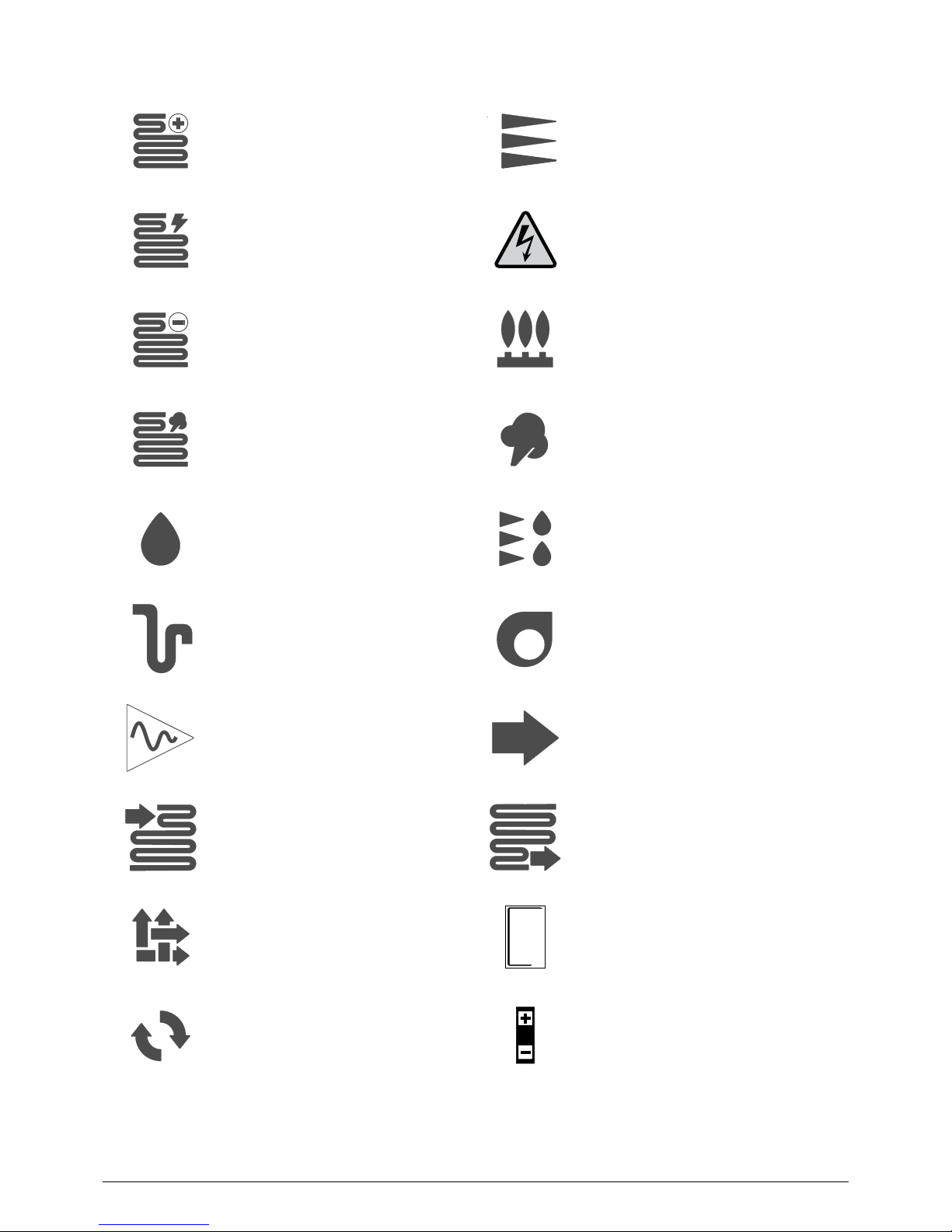
Adiabatic humidier
Plate recovery unit
Rotary heat exchanger
Droplet eliminator
Fan
Air ow
Discharge siphon
Sound attenuator
Coil outlet arrowCoil inlet arrow
FILTRES
EMPOUSSIERES
INFLAMMABLES
DANGER
D’INCENDIE
DIRTY FILTRES
ARE INFLAMMABLE
7028397.03
FIRE DANGER
Fire danger
Pressure tapping
Heating coil
Electric heater
Cooling coil
Steam coil
Electrical Box
Filter
Gas generator
Steam humidier
4.2 Pictograms
EN
EN - 5
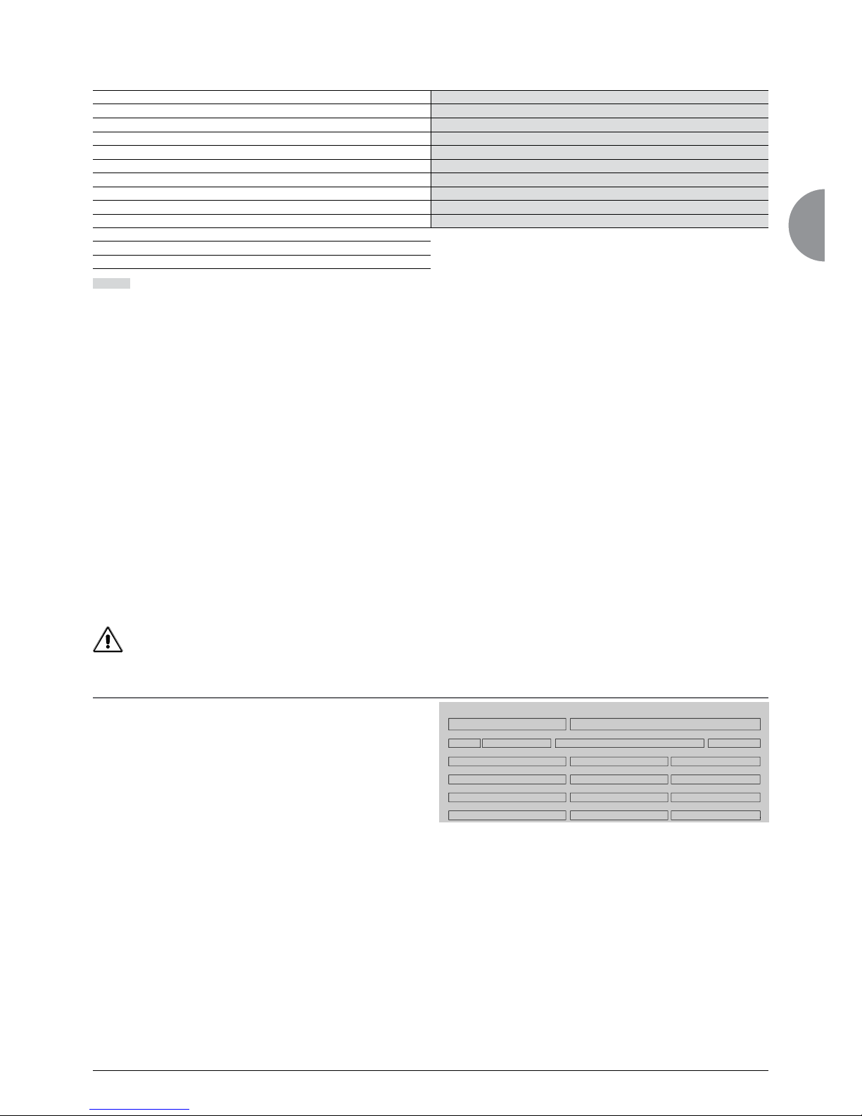
5.1 Shipping instructions
Our units must be shipped in their original packaging and in the position in which they will be used.
- Blocks must not be stacked.
- Transshipment is not permitted.
During shipping, the load must be lashed to the truck bed to prevent the unit from moving and being damaged.
- Lashing must follow accepted industry practice, using straps made from standardised synthetic fibres (EN12195-2), clearly
marked and labelled and in perfect condition.
- Leave a space of at least 100 mm between the 2 units.
- Use anti-slip blocks under the unit's feet.
5 - SHIPPING - DELIVERY - HANDLING
- We recommend top-over lashing. The straps must be tensioned manually, enough to hold the equipment securely on the
truck bed without damaging.
Do not use mechanical implements such as levers, bars, etc., unless the tensioning device is specially designed for use
with such implements.
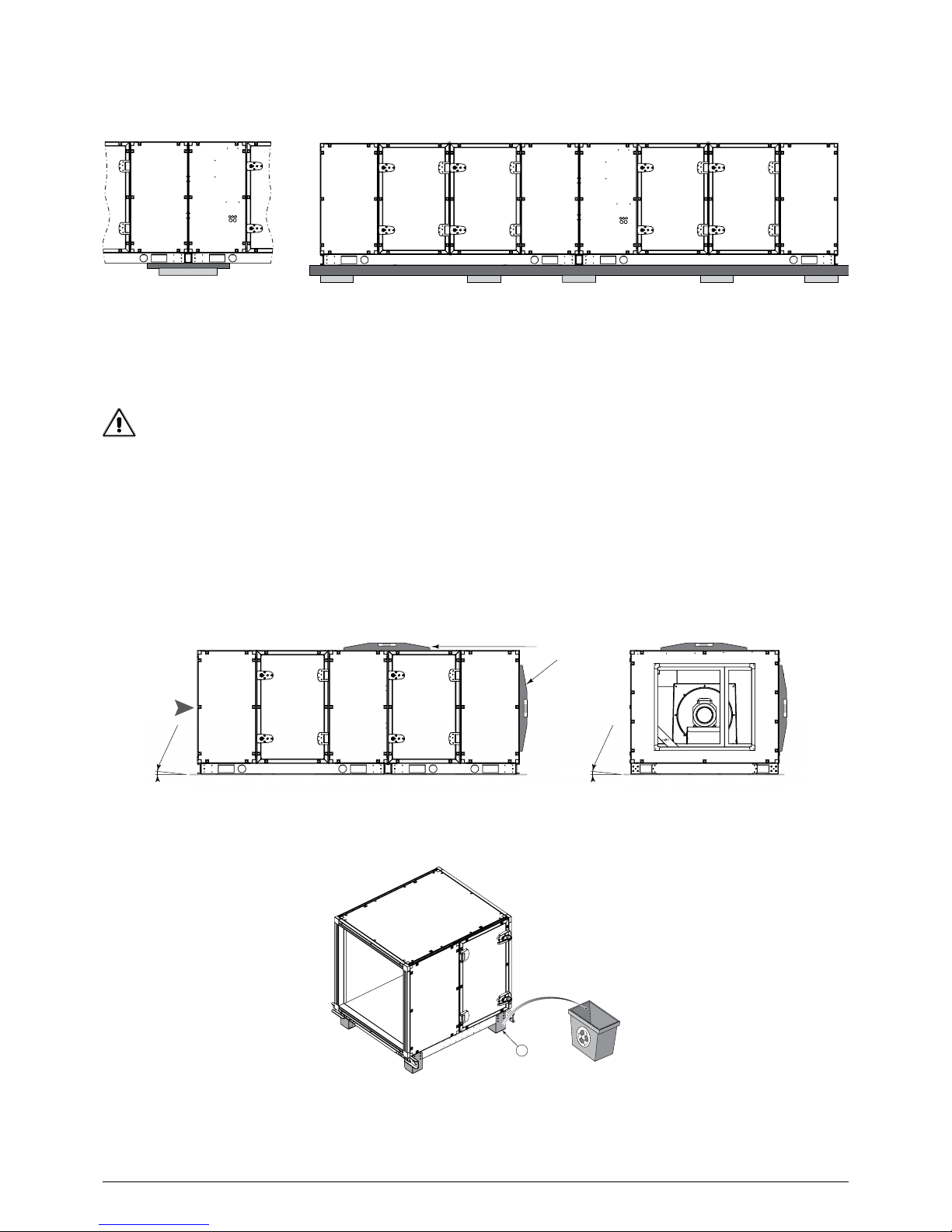
5.2 Container shipping
The container dimensions must be adapted to those of the equipment being shipped.
Slide the unit onto the container floor. When using a fork lift, place a spacer between the frame and the fork lift to prevent
damage to the unit's casing and accessories.
The straps are fed through the lifting lugs on the frame to remove the unit from the container:
- Remove the unit from the container by pulling the 2 straps.
Depending on the size and configuration, the units can be shipped in one or more blocks.
Units supplied assembled on a frame:
- The red painted steel plates and runners under the frame are used to remove the unit from the container and are removed
before installation on the site.
Do not lift the unit by its accessories.
5.3 Delivery
Upon delivery of the unit components, inspect the consignment in the presence of the driver. If any damage is observed, or
if the delivery is incomplete, indicate this in the usual way on the delivery note and confirm to the carrier by registered letter
within three days of the delivery date and send a copy to us.
WARNING: never use the terms "pending unwrapping" or "unit damaged, packaging intact", as these are not admissible for insur
ance purposes.
For any other problem, your contact will be able to explain the relevant procedure.
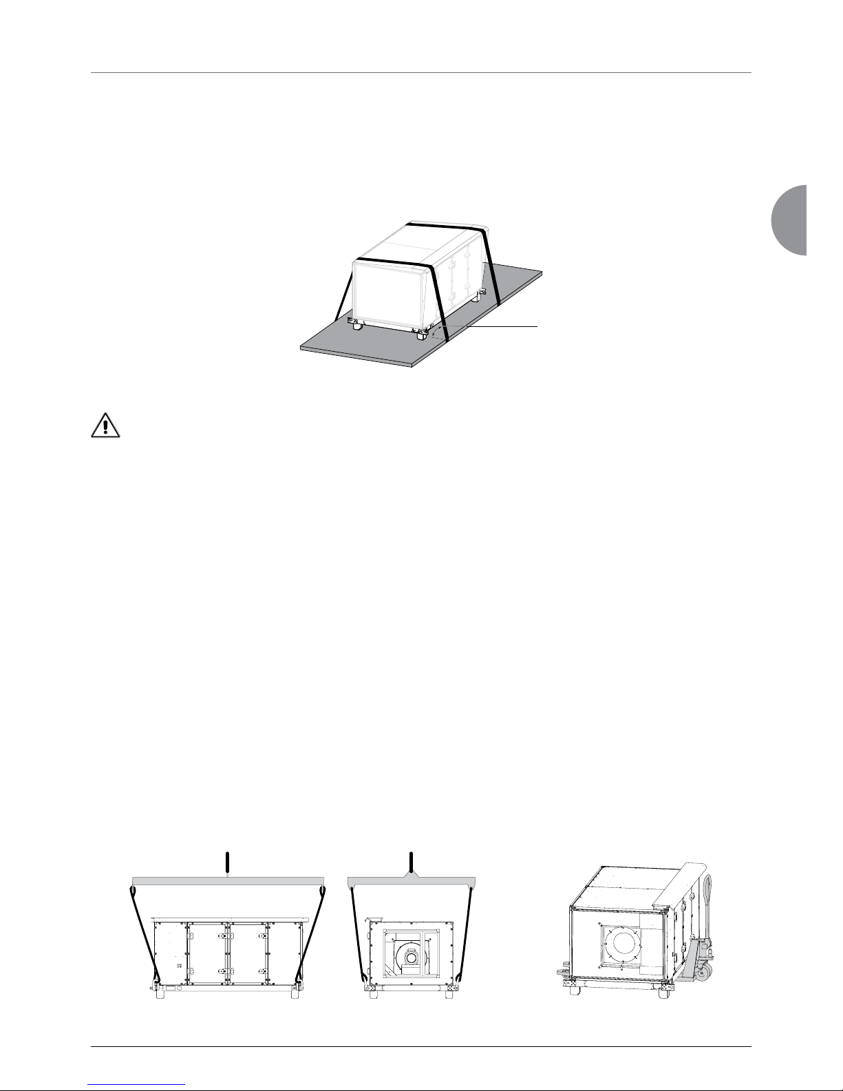
5.4 Lifting instructions
All of our units are supplied with lifting lugs.
All lifting and handling operations must be carried out in accordance with the standards and regulations applicable to the
handling location and using standardised equipment.
When handling, use lifting straps with a sufficient lifting capacity. Do not use damaged straps. Use a lifting beam adapted to
the size of the unit to prevent the straps from exerting pressure on the unit, its accessories or the roof.
When handling with a pallet truck or fork lift, make sure the forks are long enough to avoid damaging the casing. The forks
must project beyond the other side of the block.
75° to 90°
EN - 6
6 - INSTALLATION
6.1 Warning
The installation of equipment must comply with the regulations in force at the installation site.
Warning!
Follow the safety instructions in § 2 - SAFETY INSTRUCTIONS
6.2 Selecting a location
Before setting up and connecting the unit, the installer must check the following points:
- The unit's earthquake resistance has not been veried.
- These units can be placed directly on flat, level ground. The flatness value must be the best possible, around one per
thousand.
- For outdoor installation, take into account the regulations in force and the weather conditions at the installation site (risk
of snow, height from the ground, risk of wind, etc.).
- The selected location must not be liable to flooding.
- Raise the unit to ensure that the unit's operation is not affected by a buildup of snow.
- Take into account the required height of the siphon, the slope and the length of the condensate drainage container.
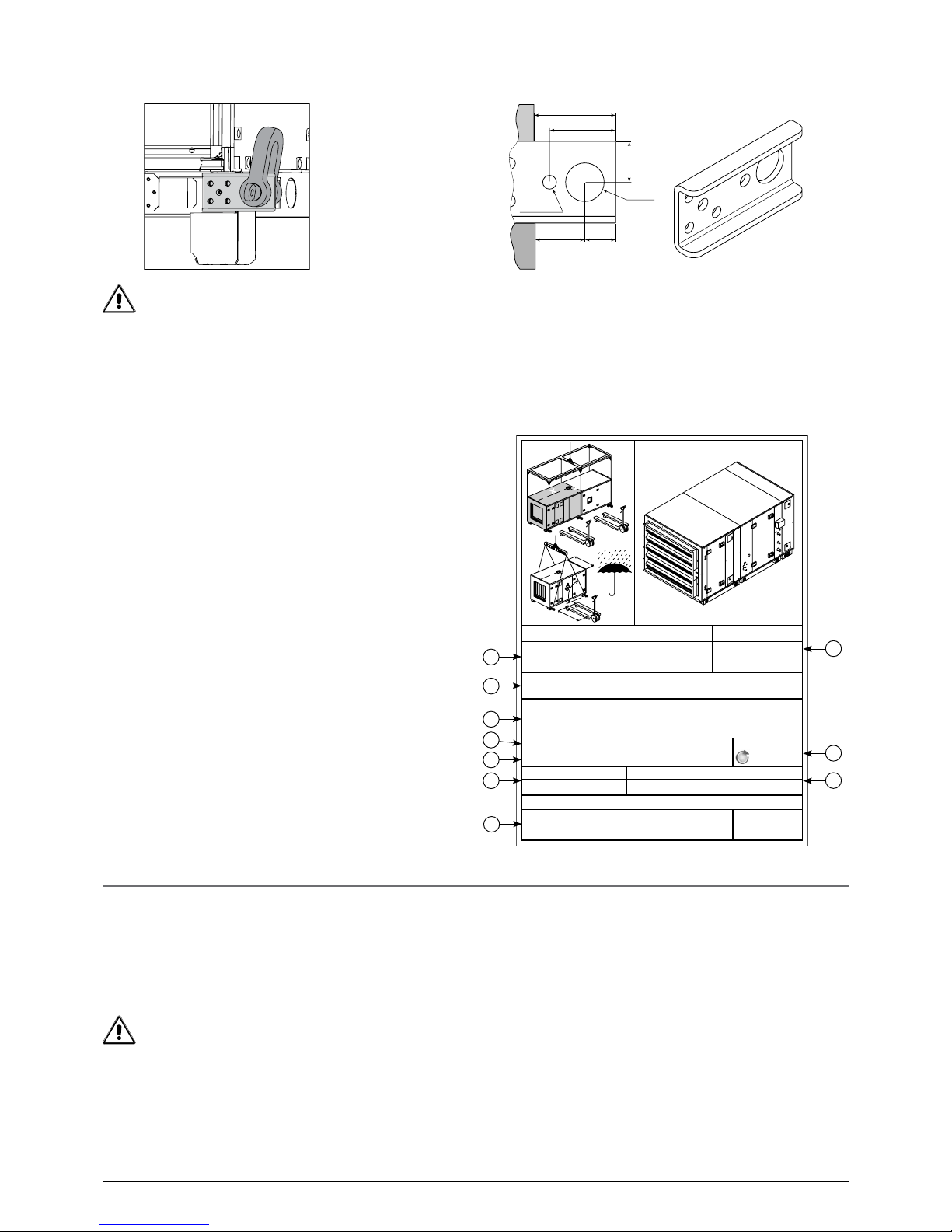
5.5 Anchoring points for handling
We recommend the use of shackles when handling these units.
These lifting lugs are used when placing blocks near each other, and must not be used once disassembled.
5.6 Storage
Do not remove the original packaging.
Do not remove the protective caps until you are ready to connect the coils.
The unit must be stored on a flat surface.
Fit protection against shocks or impacts, which could damage the unit or its accessories.
Store the blocks in their packaging, in a dry area sheltered from the weather.
The ambient temperature must be between -10°C and
50°C.
To facilitate the assembly of multisplit units, their
components must be kept in the relevant groups. Refer
to the dimensional drawings and marker labels on each
block (see opposite).
: Acknowledgement of receipt number.
: Block markings.
A1, A2, ….A9: multi-section unit.
A second unit will be marked B1, B2,…. B9.
The numbers 1, 2 and 3 do not necessarily indicate the order
of assembly (refer to the dimensional drawing).
: Internal production order = The serial number should be
quoted in all correspondence.
: Internal designation.
: Customer name.
: Pre-shipping internal inspection.
: Customer reference.
: Weight of corresponding block.
: Block year of manufacture.
: Manufacturer's name and address.
L
L
X
Y
XX
YY
ORDER NUMBER
DESIGNATION:
00001003
BLOCK
A1
CUSTOMER:
REFERENCE:
OF02376570
MASSYEAR OF MANUFACTURE
Packing conformity
2016
1
3
4
5
7
2
10
6
9
8
60
47
28
75
Ø 12.5
Ø 35
37

EN
EN - 7
- Optional extension feet are available (from 100 to 300 mm), as well as optional adjustable feet .
1
2
Flexible sleeve Support
- The hydraulic control valve kits must be supported close to their point of connection on the unit (Fig. 2)
- No connection should obstruct the unit's access doors, hatches or drawers.
Dual-flow units should be installed so as to prevent direct recirculation between the discharge and intake nozzles.
For installation in very dusty environments or areas with high pollen levels, we recommend a system of pre-filters on the fresh
air intake.
Freezing fog can very quickly block the fresh air inlet filters. Fit an air preheating system (option available) for temperatures
between approximately +3°C and -3°C.
For units equipped with a gas heater (GGS or Make-Up type), the gas connection must be made by qualified personnel in
accordance with the regulations in force at the installation site.
Sound level
Our units are designed to operate quietly.
As soon as you begin designing your system, you should take into consideration the outdoor environment to estimate the
radiated noise, and the building type for the noise transmitted through the air and by solid materials.
To minimise solid-borne vibrations, we recommend fitting anti-vibration mounts between the unit's support and frame (see
diagram below), flexible connectors on the hydraulic pipes and flexible sleeves on the ducts.
- The unit must be perfectly level (see diagram in § 6.3 Assembling the blocks).
- The surface of the ground or structure must be strong enough to bear the unit's weight.
- For outdoor installation with no weather protection, the unit must be equipped with the roof option. Make sure this option
is fitted.
- Leave sufficient space around and above the unit for servicing and maintenance operations (see dimensional drawing).
Take into account the space required to open the doors.
- Leave space equivalent to the total depth of the unit on the utilities side to allow internal components to be removed. See
dimensional drawing.
- Under normal indoor conditions of use, there is no need to fix the unit to the floor.
- Under outdoor installation conditions, the unit must be fixed to the floor (windproofing).
Depending on the regulations in force in the storage and installation location, precautions must be taken, particularly for roof
installation, to ensure that the unit is stable (strong winds, earthquake, etc.). This may involve mounting on the ground or the
support frame.
- For indoor installation, the room must conform to the regulations in force at the installation site. In particular, if the unit is
equipped with a thermodynamic system, the room must conform to standard EN 378-3 or other specifications governing
the installation location (outside EC).
- Connections must not place mechanical stresses on the unit.
- When connecting directly to the unit, the hydraulic pipes and air ducts must be held using supports close to their point of
connection on the unit (Fig. 1).
EN - 8
Have an analysis carried out by an acoustical engineer.
For units supplied in separate elements, a counter frame must be used to add anti-vibration mounts
(Fig. 2) (Frame and mounts supplied by the customer).
Fig.1 Fig.2
0 + 0.3°
0 + 0.3°
Air ow
direction
Levels
1
The unit must be grounded via its frame. Make sure all electric components are grounded.
The units are supplied with transport feet .
They must be removed and possibly replaced with risers before final assembly.
Firebreak:
Fire can spread between the supply and the return (e.g. through the heat recovery system or the mixing air).
Fit the mandatory safety devices based on the regulations in force at the installation site (e.g. re dampers).
6.3 Assembling the blocks
Ensure sufficient servicing space to allow easy maintenance and assembly of the blocks.
The blocks must be assembled in accordance with the instructions in this manual.
Electrical safety – CE marking
The manufacturer cannot declare units supplied unassembled (flat) as compliant with the low voltage or EMC directive.
Units without control systems must be electrically connected by the customer.
The components and cables must be selected in accordance with the regulations in force at the installation site.
Always comply with the overvoltage, pollution and insulation voltage categories set by the standards and regulations.
Take into account the altitude when selecting the components and cables
Reminder: For units installed in CE zones, CE certification for the complete assembled unit is the responsibility of the person
assembling it, unless the latter is a subcontractor.
Make sure the ground is flat for the purposes of installing the unit and connecting the blocks.
To ensure a tight seal between joined sections, they must be shimmed and levelled to compensate for any unevenness of the
mounting surface.
EN
EN - 9
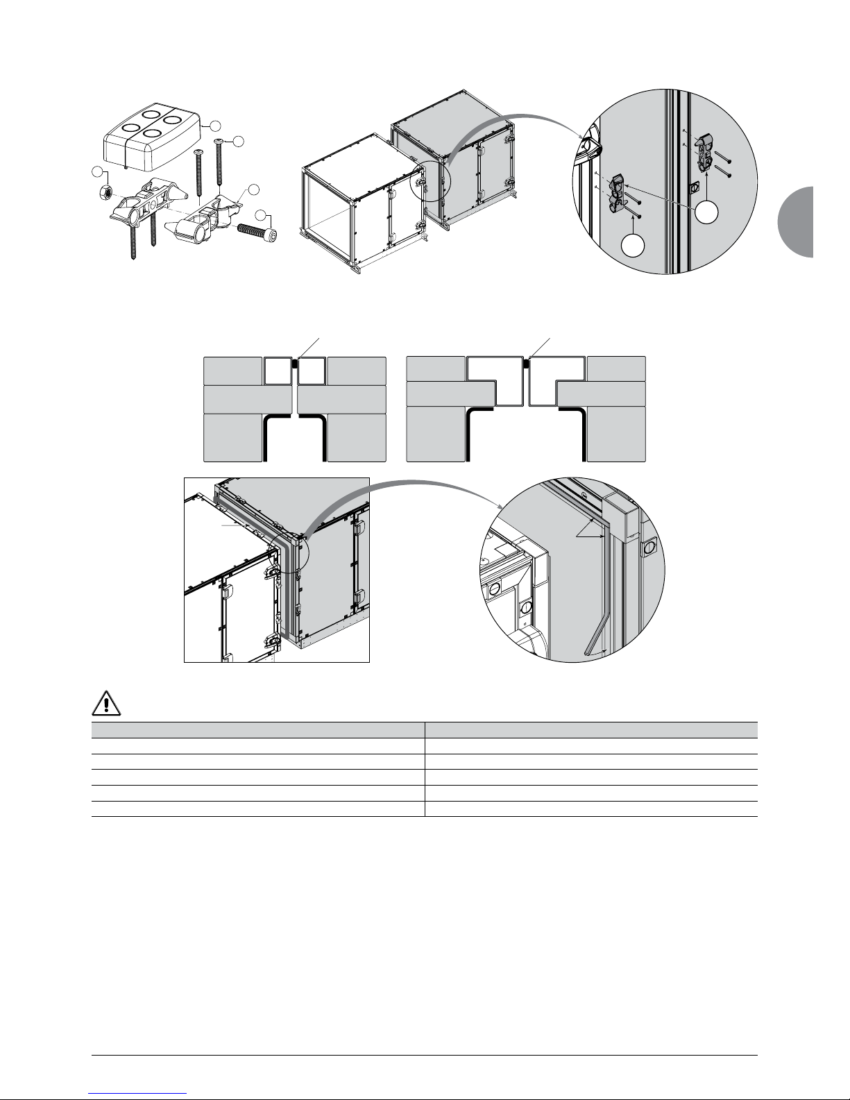
Affix the cleats (2) supplied in the connection kit (fig.A) in the dedicated holes using long screws
4.8 x 40 mm (5) in each block.
SINGLE FLOW AHU DUAL-FLOW AHU
1. Unwind the cables from the ends (the cables are prewound in the factory) 1. Unwind the cables from the ends (the cables are prewound in the factory)
2. Route the cables into the lower frame and to the vertical raceway
3. Place the cables in the raceway
4. Feed the cables through the upper raceway 4. Feed the cables through the upper raceway
5. Route downwards into the unit 5. Route downwards into the unit
5
2
1
2
3
5
4
Fig. A
Gasket Gasket
Single partition block
Single partition block
Gasket
Gasket
If the AHU has a control option.
Before the blocks are denitively brought together, the cables must be fed into the lower raceway (frame).
Fit the 15 x 9 gasket on the end partition of one block. To ensure a proper seal between two blocks, position the gasket on
the aluminium profiled edge of one block as close as possible to the inside of the unit (illustrations below).

EN - 10
Remove the lifting lugs and use a strap to bring the blocks together, taking care not to damage the front panel components.
Assembling the mixing option in 2 self-contained blocks.
- Fit a gasket on the 2 bearing faces of the insulated sleeve (sleeve supplied in the AHU).
- Afx the sleeve to the outside of the AHU against the mixing damper (4.8 x 19 sheet metal screw).
- Bring together the 2 blocks.
- Connect the sleeve to the 2nd block from the inside of the unit.
- Afx the panel to prevent access to the sleeve connection (4.8 x 19 sheet metal screw).
6.4 Adjustable feet and support cylinders
4
3
1
2
2
Description Instructions
100, 200, 300 and 400 mm height foot
1. Remove the transport feet
2. Fit the risers supplied with the M8 screws included
Adjustable foot
1. Remove the transport feet
2. Screw the cylinders underneath the unit (nuts crimped into the frame)
Adjustable foot with 100, 200, 300 and 400 mm riser
1. Remove the transport feet
2. Fit the risers supplied with the M8 screws included
3. Affix the cylinders into the extension feet with M8 screws and nuts (nuts
crimped into the foot)
Remember to t the feet halfway along the cross members for large blocks
When bringing the blocks together, make sure the various cleats (2) t together correctly.
Finalise the assembly by screwing the connecting cleats together using the metric screw (3) + M8 nut
(4) supplied in the kit.
Clip the covers onto the cleats (1).
EN
EN - 11
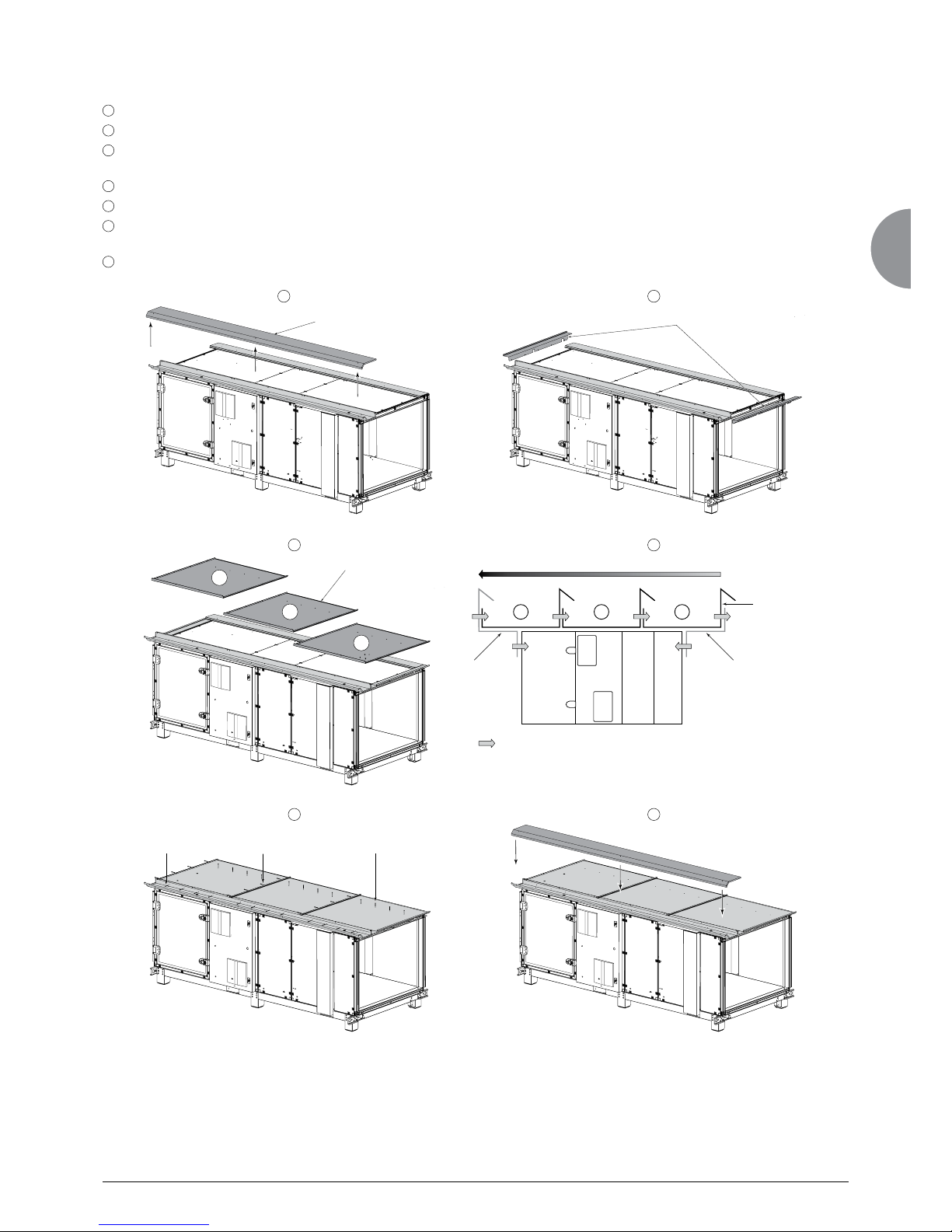
6.5 Roof/canopy (Accessories)
6.5.1 Fitting the roof
A
Remove the cover(s) from the raceway.
B
Fit the left- and right-hand blanking covers at the top of the end panels using the screws supplied in the installation kit.
C
Fit the roof panels in the order shown on the dedicated plan. Afx the panels to the raceway (from inside the raceway) using
the screws provided.
D
Fix the panels together using the screws and sealed washers supplied in the mounting kit.
E
Finally, x the panels to the omega proles, again using screws with sealed washers.
F
Fit the covers on the raceway. Make sure a 15 x 3* gasket is positioned at the ends of these covers (inter-block cover seal).
Afx them using screws with sealed washers.
G
Roof on adjacent blocks: see dedicated mounting plan.
Blanking covers
Raceway cover
A
B
Blanking
cover
Blanking cover
without return
bend
Roof
panels
Roof panel mounting direction
CTA
123
Roof panel tightening direction
1
2
3
Roof panels
DC
1
2
3
1
2
3
Mounting on
omega prole
Mounting on
the raceway
Inter-panel
mounting
E F

EN - 12
7 - CONNECTIONS
7.1. Condensate drain siphon
Connecting the siphon
Position, diameter and type of connector, see dimensional drawing.
Outlet on the front panel: Threaded gas type steel connector.
Outlet in frame: Smooth rubber female sleeve for 32 mm PVC bonding tube.
Mastic bonding is recommended for the hygiene tank connection.
The siphons and drain pipes must be insulated and protected from frost (heating cable).
The siphons must not be directly connected to the waste water network.
Siphon calculation:
H in mm = Pa / 10
Pa = Pressure difference (in Pascal) between the inside and outside of the unit.
Assembly with depression : Assembly with pressure:
7.2 Heating/cooling coil
7.2.1 Coil supply:
Follow the instructions on the labels:
Observe the counter-ow principle
- Fluid inlet downstream of the air flow direction
- Fluid outlet upstream of the air flow direction
7.2.2 Connection
Refer to your dimensional drawing for the diameters of the connections and their positions.
Before connecting, make sure the inside of the hydraulic system pipes is perfectly clean and free from debris or deposits.
The pipe routing and insulation must not obstruct the removal of the heat exchanger for replacement or maintenance. Use
removable connectors and insulation components (valves).
The system pipes must be affixed to the walls, ceiling or floor of the building, and must under no circumstances exert an
additional load on the unit. Make sure the pipes are supported.
The pipes must not transmit any thermal or vibrational stress to the heat exchanger. Use expansion sleeves. Do not use
galvanised connectors. Check the material compatibility (risk of electrolysis).
The pipes must be insulated to prevent condensation and heat loss.
Make sure the insulation is no thicker than 40 mm to leave enough space to open the doors or removable panels.
Inlet Outlet
To sewer
system
1.5H
0.5H H
To sewer
system
2H
0.5H H
Assembly with several coils in parallel:
OK
EN
EN - 13
Connecting the condensate drainage: See § 7.1 "Condensate drain siphons".
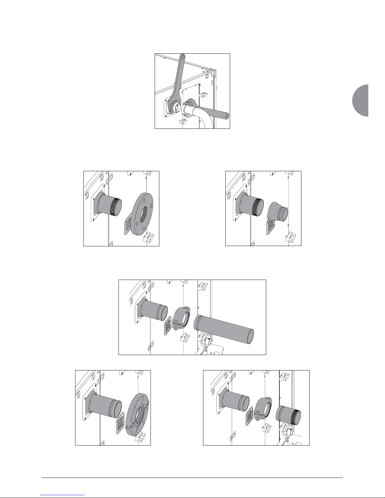
Connection types:
Heat exchangers with cylindrical threaded connectors with flat gaskets.
Heat exchangers with grooved connectors. Optional threaded connector or flange adaptor kits are available.
Heat exchangers with "Victaulic" type grooved connectors.
- Follow the instructions from the connector manufacturer when preparing and aligning the pipes.
- Do not use zinc-coated or galvanised connectors or pipes.
- WARNING: Check the compatibility of the materials (risk of electrolysis).
- Always use two spanners when connecting or tightening the hydraulic couplings to avoid twisting the pipes and applying
stress on the welds.
- Do not use zinc-coated or galvanised connectors or pipes.
- WARNING: Check the compatibility of the materials (risk of electrolysis).
Heat exchangers with threaded connectors. Screw flange or Victaulic type grooved connector adaptor kits are available
 Loading...