

Page 1

NA 13.12 B
03 – 2015
AirCompact Control
AirCompact
Control manual
Page 2

2
CONTENTS
1
Supervision and control ...................................................................................................................... 4
1.1 The program................................................................................................................................................... 4
1.2 The HMI terminal ........................................................................................................................................... 4
1.2.1 Using the HMI terminal keys .................................................................................................................................. 5
1.3 The room terminal (Option) ....................................................................................................................... 6
1.3.1 Controls ..................................................................................................................................................................... 6
1.3.2 Displays ..................................................................................................................................................................... 7
1.3.3 Room terminal information, settings and browsing ............................................................................................. 8
1.3.4 Managing alarms...................................................................................................................................................... 8
1.3.5 Electrical connections ............................................................................................................................................ 10
1.4 The controller .............................................................................................................................................. 11
1.5 Description of the air handling units ..................................................................................................... 11
1.6 Functional analysis of the control ......................................................................................................... 12
1.6.1 Management of on and off modes ....................................................................................................................... 12
1.6.2 Safety and insulating damper ............................................................................................................................... 12
1.6.3 Antifree ze therm os tat ............................................................................................................................................ 12
1.6.4 Fire fault................................................................................................................................................................... 12
1.6.5 Fan motors .............................................................................................................................................................. 13
1.6.6 Filtration ................................................................................................................................................................... 13
1.6.7 Temperature control .............................................................................................................................................. 14
1.6.8 Plate recovery ......................................................................................................................................................... 17
1.6.9 Electric heater ......................................................................................................................................................... 17
1.6.10 Free cooling ........................................................................................................................................................ 18
1.6.11 Humidifier ............................................................................................................................................................ 18
1.6.12 CO2 air quality..................................................................................................................................................... 18
1.6.13 Night cooling ....................................................................................................................................................... 19
1.6.14 The fault relays ................................................................................................................................................... 19
1.7 Controller inputs and outputs ................................................................................................................. 20
1.7.1 Analogue inputs ..................................................................................................................................................... 20
1.7.2 Digital inputs ........................................................................................................................................................... 20
1.7.3 Analogue outputs ................................................................................................................................................... 20
1.7.4 Digital outputs ......................................................................................................................................................... 20
2
Overview of the HMI module screens ............................................................................................ 22
2.1 Esc button .................................................................................................................................................... 22
2.1.1 Access level selection menu ................................................................................................................................ 23
2.2 Setpoint menu ............................................................................................................................................. 23
2.3 Machine parameters menu ....................................................................................................................... 25
2.4 Adjustment parameters menu ................................................................................................................. 28
2.5 Read-only parameters menu ................................................................................................................... 31
2.5.1 Inputs ....................................................................................................................................................................... 31
2.5.2 Outputs .................................................................................................................................................................... 32
2.5.3 Calculated setpoints .............................................................................................................................................. 33
2.5.4 Counters .................................................................................................................................................................. 33
2.6 Fault memory menu ................................................................................................................................... 34
Page 3

3
2.7 Versions menu ............................................................................................................................................. 35
2.8 Time schedule menu .................................................................................................................................. 35
2.9 Communication menu ................................................................................................................................ 37
2.10 Alarms menu ............................................................................................................................................. 37
2.11 Test mode menu ...................................................................................................................................... 37
2.12 Access level menu .................................................................................................................................. 39
2.13 Master/Slave menu .................................................................................................................................. 40
3
Managing a network of controllers ................................................................................................. 40
3.1 pLAN electrical connections .................................................................................................................... 40
3.1.1 Connecting controllers to the pLAN ..................................................................................................................... 40
3.1.2 Connecting a remote screen to the pLAN .......................................................................................................... 41
3.2 Addressing the pLAN ................................................................................................................................. 42
3.3 Changing the controller address ............................................................................................................ 42
3.3.1 Addressing the HMI terminals .............................................................................................................................. 42
3.3.2 Assigning private and shared terminals .............................................................................................................. 43
3.3.3 Checking the pLAN address ................................................................................................................................. 44
3.4 State of the pLAN ........................................................................................................................................ 44
4
Replacing the lithium battery ........................................................................................................... 44
5
Supervision ........................................................................................................................................... 44
5.1 CMS ................................................................................................................................................................. 44
5.2 The datapoint database ............................................................................................................................. 45
5.3 Modbus .......................................................................................................................................................... 45
5.3.1 Modbus RTU connection diagram ....................................................................................................................... 45
5.3.2 RS485 connection close-up .................................................................................................................................. 45
5.3.3 Modbus TCP connection ....................................................................................................................................... 46
5.3.4 Variables .................................................................................................................................................................. 47
5.3.4.1 Commands ..................................................................................................................................................... 47
5.3.4.2 Setpoints ........................................................................................................................................................ 47
5.3.4.3 Reading parameters .................................................................................................................................... 49
5.3.4.4 Alarms ............................................................................................................................................................. 51
5.4 LON ................................................................................................................................................................. 52
5.4.1 LON scope of supply ............................................................................................................................................. 52
5.4.2 The digital datapoints............................................................................................................................................. 52
5.4.3 The analogue datapoints ....................................................................................................................................... 54
5.5 KNX ................................................................................................................................................................. 55
5.5.1 Description of KNX communication card ............................................................................................................ 55
5.5.2 Variables .................................................................................................................................................................. 56
5.5.3 Configuration process ............................................................................................................................................ 62
5.5.4 CAREL plugin ......................................................................................................................................................... 62
5.5.5 Installing the plugin ................................................................................................................................................ 62
5.5.6 Assigning the physical address ............................................................................................................................ 64
5.5.7 Downloading the XML file ..................................................................................................................................... 65
6
Table of alarms ..................................................................................................................................... 66
Page 4
4
1 Supervision and control
1.1 The program
This air handling unit is managed by its controller. In addition to its control functions, it also monitors and detects any faults with the
air handling unit.
The HMI terminal displays the following data which can be edited at any time:
. values of connected sensors
. unit on/off cycles
. calibration of the sensors
. detection of alarms and log of the last 100
. the password-protected configuration and operating parameters
. device running times and time delays
. management of time programs (4 daily, 4 weekly and 4 yearly programs)
. language selection (French)
The connection with the pLAN network allows the program to use a terminal mounted on the front of the AHU and/or a wallmounted terminal installed in the room to be air conditioned.
IMPORTANT: To avoid any problems, the password must be known only by qualified personnel.
1.2 The HMI terminal
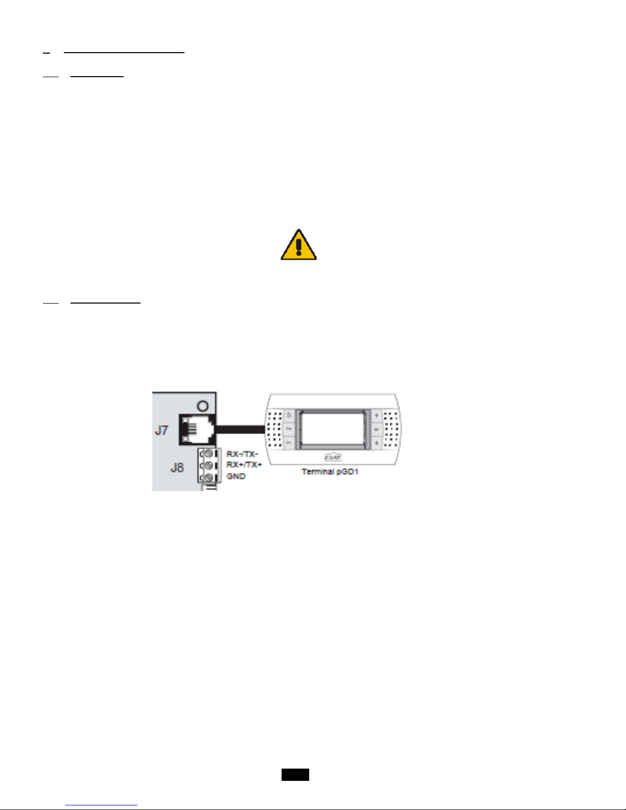
The terminal provided is equipped with a remote LCD display (8 lines x 22 columns) on the outside of the unit, which has 6 keys
(connected with a phone cable, max length 50m). It allows all of the program operations to be carried out. The terminal displays the
unit's operating conditions at any point in time and allows the parameters to be modified; in addition, it can be disconnected from
the main board as its presence is not strictly required.
Page 5
5
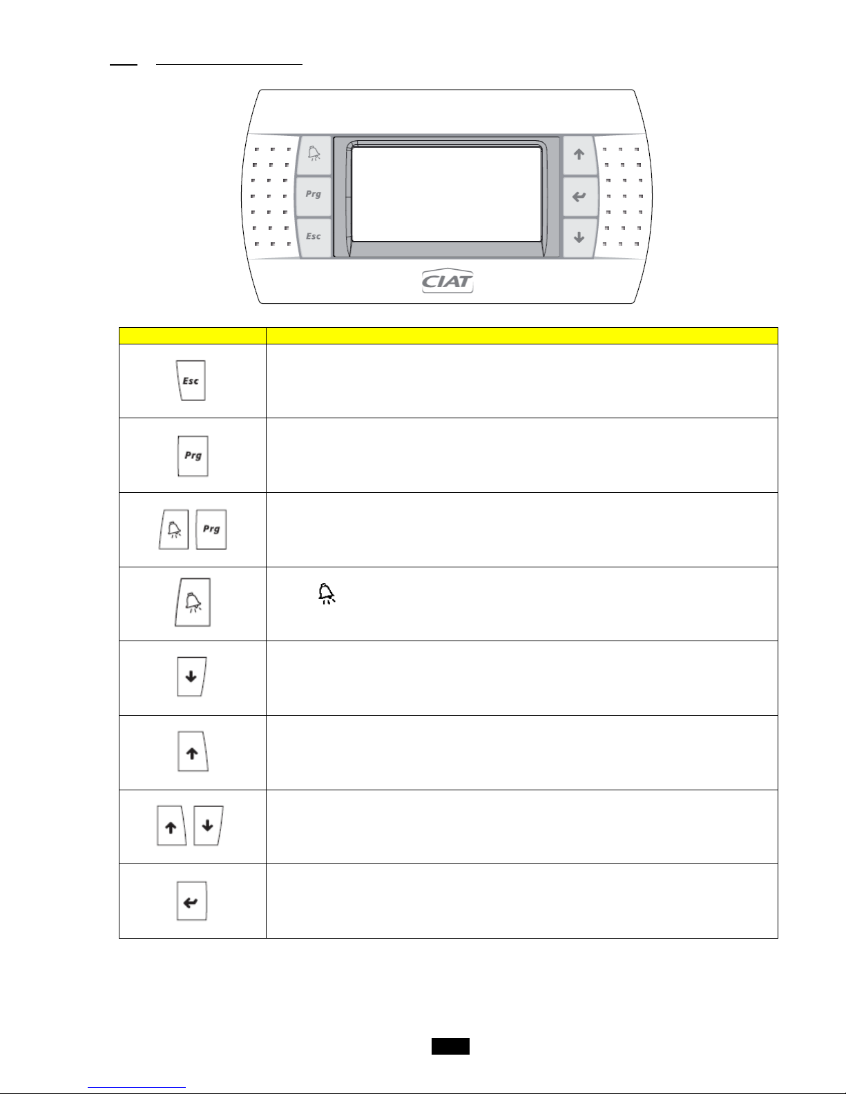
1.2.1 Using the HMI terminal keys
Key
Description
Returns to the main Menu mask when pressed in any loop.
The Menu loop displays the state of the unit.
Provides access to the "Menu"
Resets all setpoints, parameters and time delay values to their factory settings.
The red button is used to display alarms and confirm acknowledge abl e fault s. It light s up
when an alarm is triggered.
The button has two functions:
1. used to manage the masks on the display (next mask)
2. used to adjust the values of the monitoring parameters (decrease)
The button has two functions:
1. used to manage the masks on the display (previous mask)
2. used to adjust the values of the monitoring parameters (increase)
Turns the unit on and off.
The button is used to confirm changes. It is continuously backlit to indicate when the power is
on.
Page 6
6
1.3 The room terminal (Option)
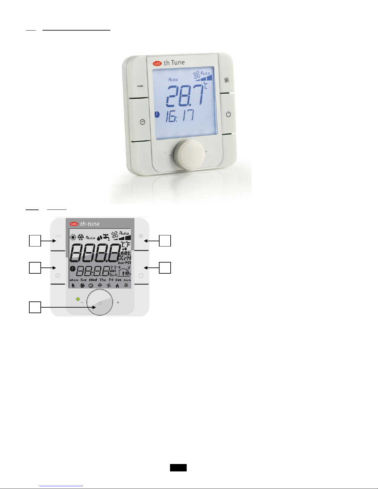
The terminal supplied is equipped with a digital display, 4 buttons and a rotary encoder.
Once installed in the premises, the device can measure the room temperature and enables remote control of the air handling unit.
1.3.1 Controls
1. Button not used
2. A short press will activate or deactivate operation in timed
zones if the time slot option has been authorised.
Press and hold (2 s) to access the tim er and timed zones
setting menu.
3. Button for changing the ventilation speed
4. Button for switching the unit on or off (press and hold for 2s)
5. Encoder:
- Press to access the setpoints and confirm
- Turn to browse between menus and modify the parameters
1 2 3 4 5
Page 7
7
1.3.2 Displays
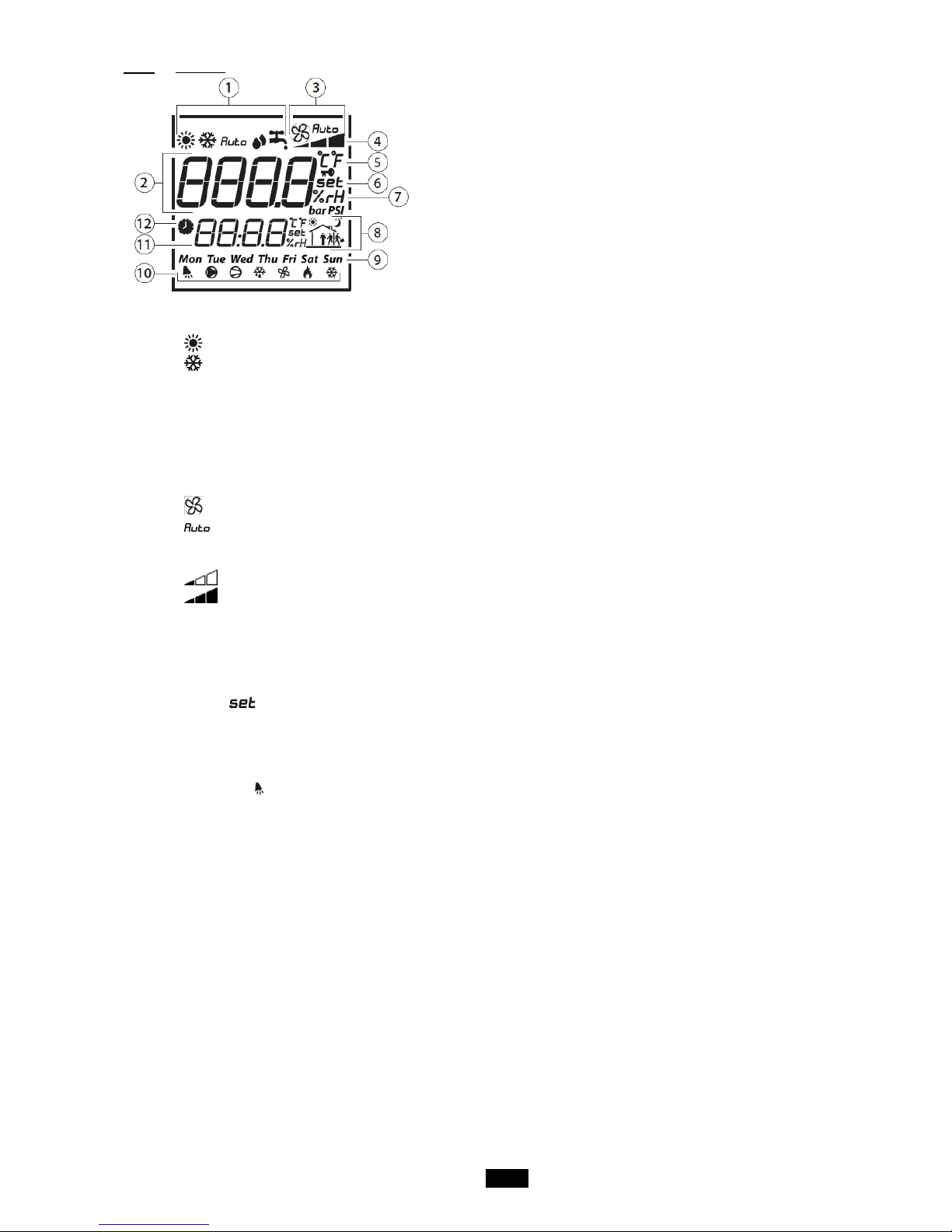
1. Unit operating mode
2. Main display area (Big area)
3. Ventilation operating mode
4. Ventilation operating speed
5. Temperature unit
6. Indicates whether the value displayed in the main area is a setpoint
7. Indicates whether the value displayed in the main area is a humidity
8. Indicates the active time slot zone
9. Day of the week
10. Operating icons
11. Secondary display area (Small area)
12. Run time range mode
Details:
1. Unit operating mode
- : Unit in heating mode
- : Unit in cooling mode
2. Main display area
- Displays "OFF" when the unit is switched off manually via the room terminal
- Displays the ambient temperature
- Displays the temperature s etpoint when the encoder is turned
- Displays the various menus during browsing
- Displays the various setting parameter s
3. Ventilation operating mode
- : Indicates that the ventilation is active and in setpoint-based flow or Supply air duct pressure mode.
- : Indicates that the ventilation is in automatic mode based on the regulated temperature.
- No display: the unit has been switched off by the HMI terminal, by a major fault or to Standby by a time program.
4. Ventilation operating speed
- : The ventilation is operating at reduced flow or Eco Supply air duct pressure
- : The ventilation is operating at a nominal flow rate or Comfort Supply air duct pressure
5. Temperature unit
- °C: temperature expressed in degrees Celsius
- °F: temperature expressed in degrees Fahrenheit (not used)
6. Indicates whether the value displayed in the main area is a setpoint
After the encoder has been turned and then pressed, it is possible to modify the temperature setpoint characterised by the
indicator .
7. Area not used
8. Area not used
9. Area not used
10. Operating icons
Only the bell is used. It indicates the presence of a fault. This icon is inhibited when the faults are c leared via the HMI
terminal.
11. Secondary display area
Displays the time on the controller. This area can also be used for mod ify ing the control ler time.
12. Run time range mode
Page 8
8
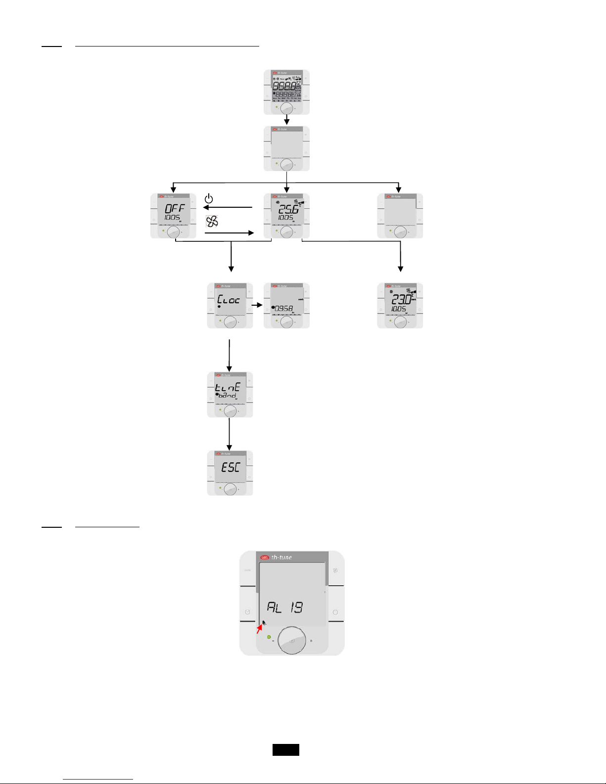
1.3.3 Room terminal information, settings and browsing
The diagram below shows the various browsing, information and setting options on the room terminal:
Terminal energising
A few seconds (2-3s)
Terminal initialising
A few seconds (2-3s)
Unit off
pressed
pressed
Unit on
(default
screen)
Communication fault
with the controller or
terminal presence not
validated in the controll er
pressed and held
Encoder turned and pressed
Clock
modification
To modify and validate
the temperature setpoint.
Returns to the default
screen after a few
seconds.
Encoder turned
Not used
Encoder turned
Exits the alarm menu when
the encoder is pressed.
1.3.4 Managing alarms
When an alarm appears, it is accompanied by an acronym on the screen:
u1.3
Cn
Page 9
9
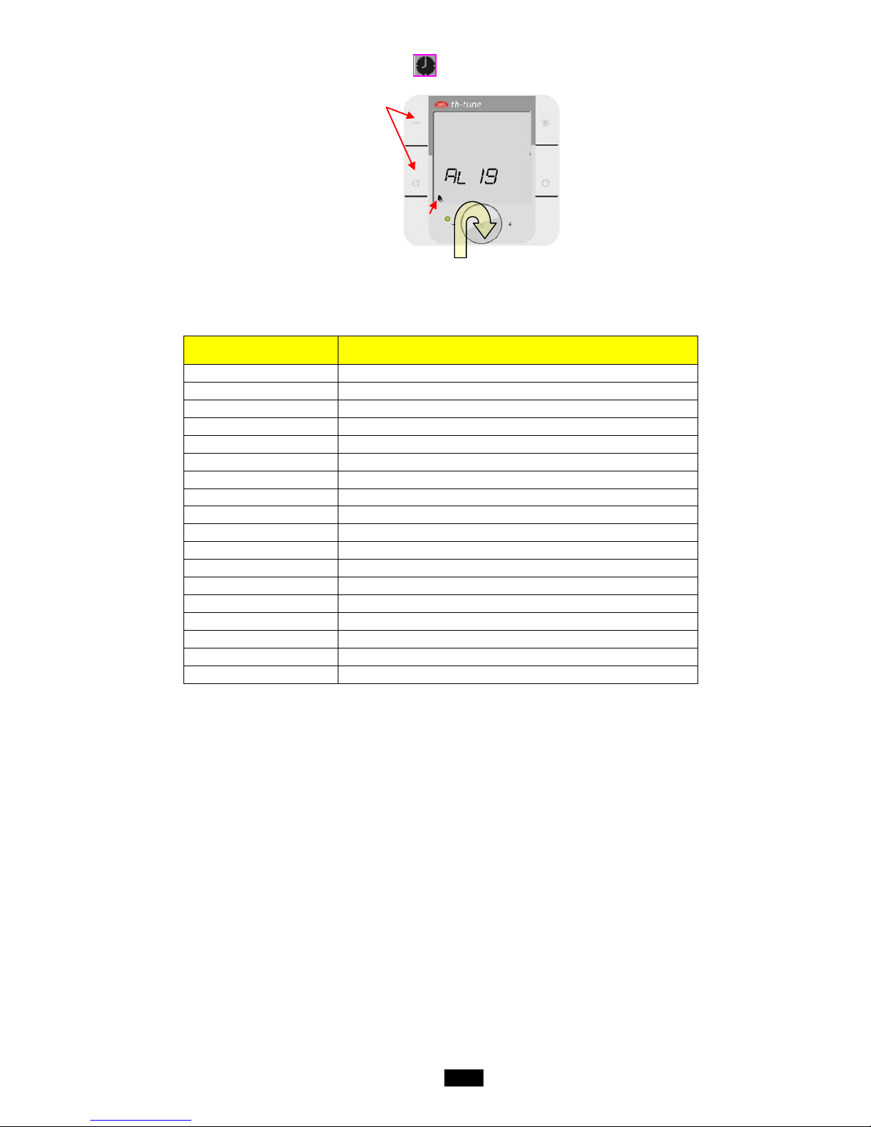
To find out the reference for the alarm, simply press the and "mode" buttons for 3s:
To find out whether there is more than one active alarm, turn the encoder to access the full list.
List of alarms:
Messages
Room terminal
Messages
HMI terminal
AL01
Supply air motor
AL02
Return air motor
AL03
Supply air filter CF1 dirty
AL04
Supply air filter CF1 clogged
AL05
Return air filter CF1 dirty
AL06
Return air filter CF1 clogged
AL07
Filter CF2 dirty
AL08
Humidifier
AL09
Heat exchanger frosted
AL10
Antifreeze thermostat
AL11
Electric heater safety thermostat
AL12
Supply air temperature too low
AL13
Supply air temperature too high
AL14
Regulated temperature too low
AL15
Regulated temperature too high
AL16
Supply air duct pressure s ensor
AL17
Replace the controller battery
AL18
Fire
The disappearance of an alarm is always confirmed via the HMI terminal.
Page 10

10
1.3.5 Electrical connections
Rx- Rx+
GND
L N
24VAC
The room terminal and the controller are electrically connected using an AWG20/22 shielded cable (not supplied by CIAT)
comprising two twisted pairs.
The first and last controller must be no more than 500m apart. This network must never run parallel to power cables at a distance
of less than 50 cm. These cables may cross, but perpendicularly. You are requested not to form a loop with the network cable or
the earth braid, and to properly separate the various cable families (control, power, earth and communication bus).
In case of transmission problems, it is vital to connect a 120Ω ¼W electrical resistor between terminals TX+ and TX- of the room
terminal, as indicated in the manual supplied with the room terminal.
Page 11
11
1.4 The controller
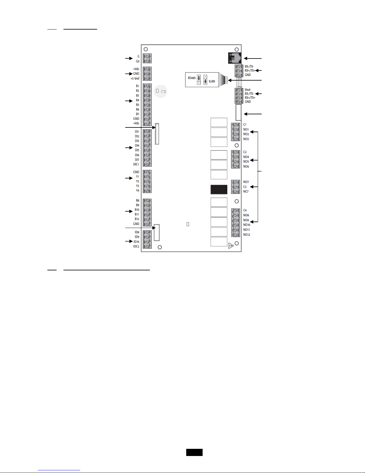
The descriptions of the terminals on the controll er are provided below.
Controller power supply (24Vac -25
VA maximum)
Passive sensors power supply
Analogue inputs for the sensors
NTC - 0/1V - 0/5V
Communication expansion board port
(Modbus, LON, KNX)
On/Off inputs
Analogue outputs
0/10V - 8-bit resolution
Analogue inputs for the sensors
NTC - 0/1V - 0/5V
Valve output (not used)
On/Off inputs
RJ11 connector for the pGD1
configuration terminal (pLAN)
3-point connector to connect up other
units (pLAN)
Configuration connector for the
FIELDBUS port
FIELDBUS port
(configured in tLAN)
Valve output (not used)
On/Off outputs
24Vac - 1A - 100,000 cycles
1.5 Description of the air handling units
Each air handling unit performs the following functions:
- Air filtration.
- Supply and return air ventilation (option).
- Heating of the air supplied to the room by means of a hot water coil or a n electr ic heat er .
- Heat recovery using a plate heat exchanger (option).
- Cooling of the air supplied to the room by means of a cold water coil or a condensation unit.
- Control, monitoring, reporting and regulation of its components.
Page 12
12
1.6 Functional analysis of the control
1.6.1 Management of on and off modes
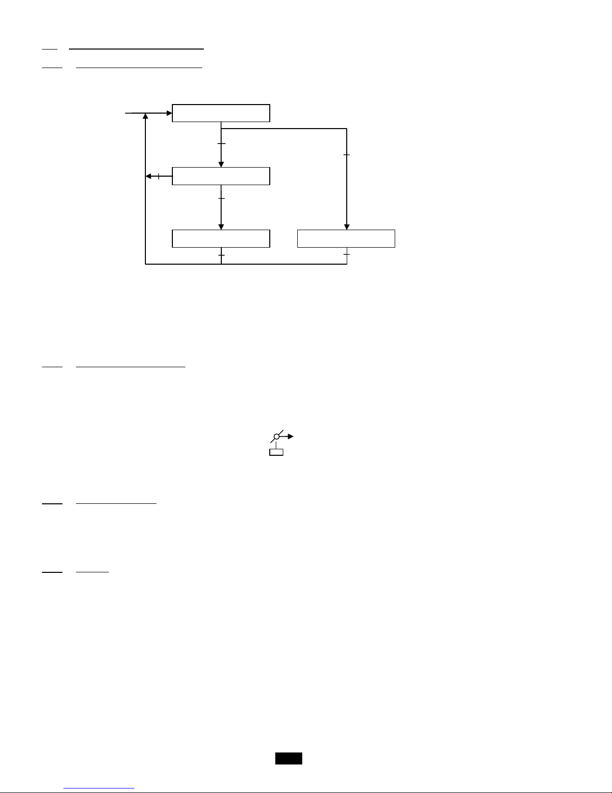
Starting up and switching off will take place locally by pressing on the and keys on the display.
Remote control is available and carried out by a potential-free contact between terminals 1 and 2 in place of the factory-installed
shunt.
The unit is to be switched on/off by the CMS.
The unit will start up if the 3 running orders are actuated (on the display, on the remote control and via the CMS, depending on the
configuration).
If one of the 3 orders is in "Off" mode, the unit will be stopped.
1.6.2 Safety and insulating damper
The insulating damper is activated by an On/Off servomotor with spring-return.
When the unit is stopped, this damper is normally c losed.
When unit start-up is requested, it will open and the controller will wait whilst the servomotor opens, then the unit will be switched
to "On" and the damper held open unit the next request to stop the unit or, if a safety damper is being used, for the appearance of
the antifreeze protection alarm.
1.6.3 Antifreeze thermostat
The antifreeze thermostat has a manual reset and it is constantly monitored once the controller is switched on.
If an antifreeze alarm is activated, the fresh air damper is closed, the valves on the hot water coil installed in the air handling unit
are opened fully and the fault is signalled.
A frost prevention function is available onc e the unit is switched off. This consists of leaving the hot water coil valves slightly open
(adjustable value) to maintain pre-heating.
1.6.4 Fire fault
The fire fault contact (option) connected to a PLC input is used to signal the appearance of the fire fault and disables the fans.
Air flow rate OK
Unit off
Unit powered up
Unit on
Manual mode
Switching on
OR critical fault
On request
AND on authorisation
AND NO crit ical fa ult
At least 1 override requested
No override requested
Off request
Off request
SMR
Page 13
13
1.6.5 Fan motors
The motor or motors start when the unit is in "On" mode.
The alarm feedback from the motor(s) is used to check their electronic switching protection. If one or other of these signals is not
received, the unit is stopped and the faults are signalled.
Their rotation speed is c ontrolled using one of the 2 following modes:
1. to maintain the fans at a constant flow ("Flow rate") in accordance with the setpoint(s) on page w0, based on the
configuration on page p3 of the "Adjustment parameters" menu and the air quality setpoint (option) until the
maximum flow rate limit on page w3 is reached.
2. to maintain a constant pressure in the supply air duct ("Pressure") in accordance with the setpoint on page w1 and
based on the configuration on page p3 of the "Adjustment parameters" menu.
Control modes available for the managemen t of fans
Flow rate
Pressure
1.6.6 Filtration
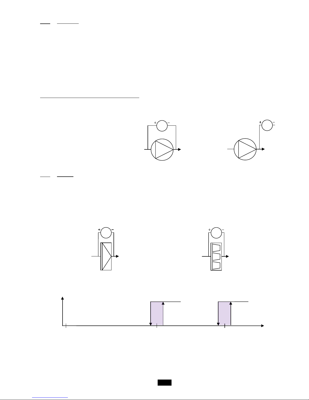
3 different filters can be monitored simultaneously: 1 in the Supply air flow, 1 in the Return air flow and 1 additional filter in either of
the 2 flows.
To check their fouling level, each filter is equipped with a differential pressure sensor which measures its upstream/downstream
pressure drop. This sensor has a measuring range of 0-1250 Pa. In addition to monitoring the fouling level, this sensor also checks
for the presence of an air flow crossing the filter, and therefore the unit, in both directions (Supply and return air). This information
is required for activating the regulation.
For the additional filter, its pres sure drop is checked by a pressure switch which will provide information on the saturation level
reached in the controller via a contact.
or
PS
∆p
Bag filter
∆p
PS
Gravimetric filter
PS
MS
∆p
∆p
PS
MS
Filter
pressure
drop
Dirty filter
detection
threshold
0
Pa
Clogged
filter
detection
threshold
Page 14
14
1.6.7 Temperature control
The regulated temperature may be:
- the return air temperature
- the room temperature
- the supply air temperature
Two temperature control schemes are availa ble:
- "Precision" mode, where a low deviation from the reference temperature is requested.
- "Energy optimisation" mode, where the key factor is the cost of energy.
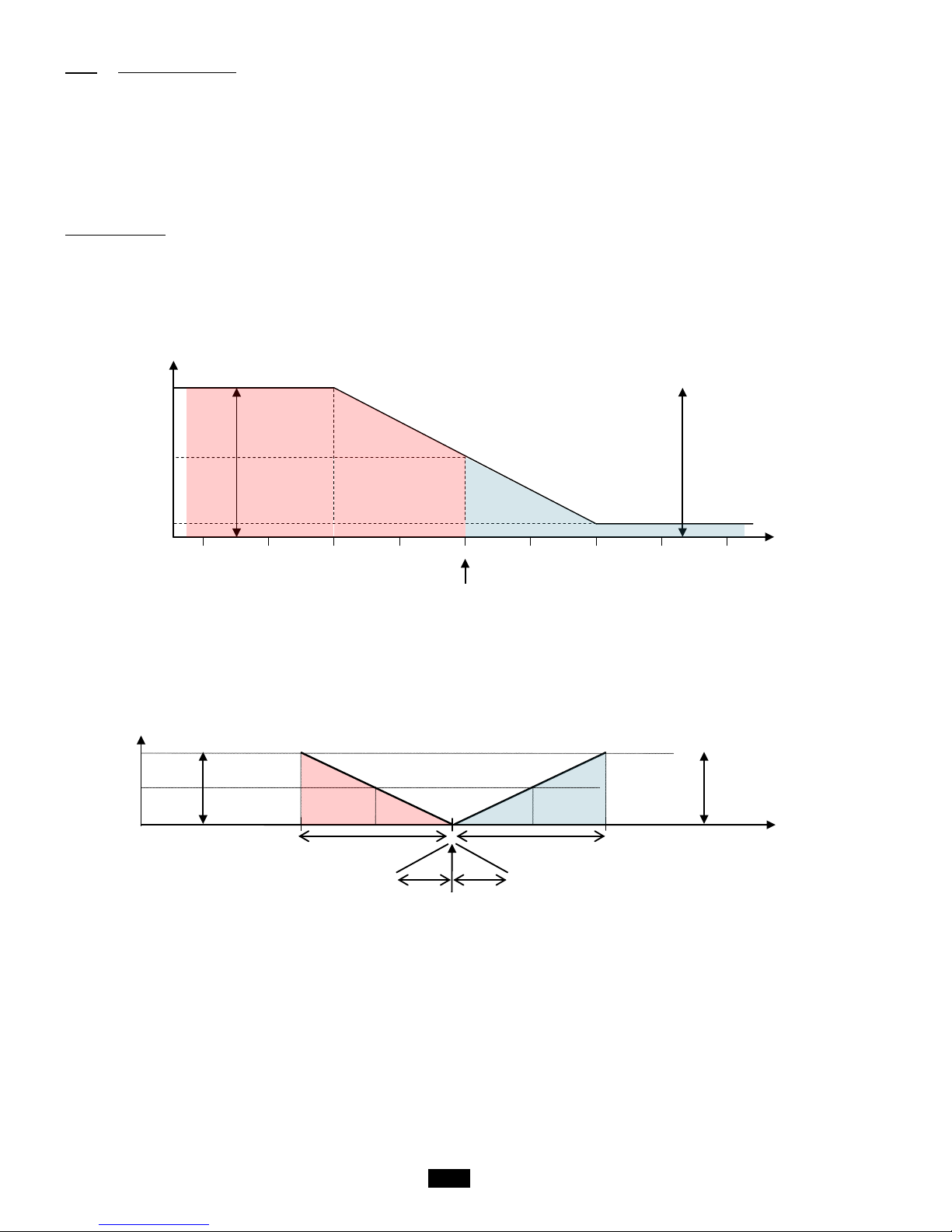
"Precision" mode:
In this case, the regulated temperature is the room or return air temperature and the difference between this temperature and the
setpoint enables the setpoint used as the basis for controlling the supply air temperature to be calculated.
Return T°
Ambient T°
Low
threshold
alarm
High
threshold
alarm
lower limit
upper limit
°C
X2
X1
Setpoint
Calculated Supply air T°
setpoint
Setpoint
Comfort: 20°C
Eco: 16°C
Comfort: -5°C
Eco: -7°C
Setpoint - 5°C Setpoint + 5°C
Comfort: 5°C
Eco: 7°C
Supply air temp.
setpoint
band
band
neutral
neutral
°C
Cooling requirement (%)
0
100
50
Heating requirement (%)
High
threshold
alarm
Setpoint + 5°C
Low
threshold
alarm
Setpoint - 5°C
Page 15
15
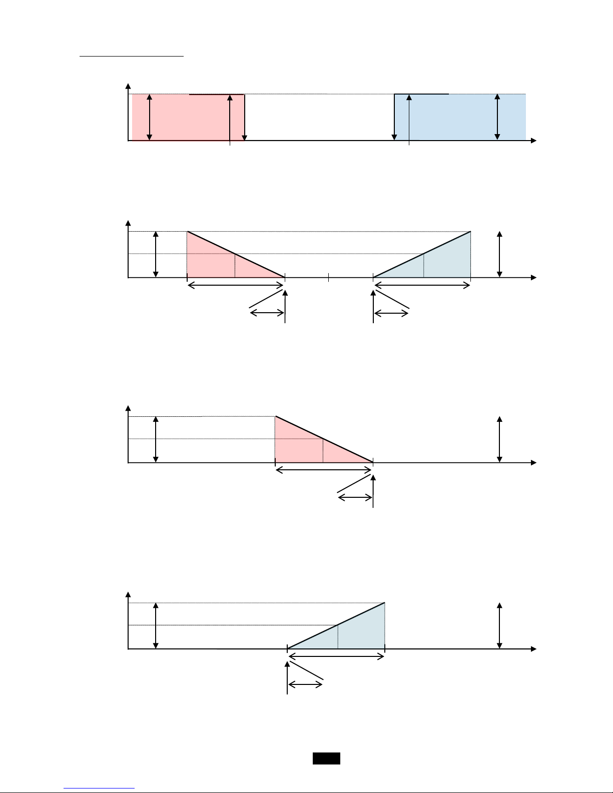
"Energy optimisation" mode:
Deadband:
Heating:
Cooling:
Return T°
Ambient T°
Heating
authorised
Heating
setpoint
Comfort: 23°C
Eco: 18°C
Cooling authorised
Deadband
Cooling
setpoint
Comfort: 25°C
Eco: 27°C
Low
threshold
alarm
Setpoint - 5°C
High
threshold
alarm
Setpoint + 5°C
°C
Supply air
temp.
Cooling requirement (%)
0
100
50
band
Setpoint
Cooling Air supply
Comfort: 16°C
Eco: 18°C
neutral
Low
threshold
alarm
High
threshold
alarm
Setpoint
Cooling supply air– 5°C
Comfort: 13°C
Eco: 11°C
Setpoint
Heating supply air + 5°C
Comfort: 31°C
Eco: 29°C
neutral
°C
Supply air
temp.
Supply a
Setpoint
Heating Air supply
Comfort: 26°C
Eco: 24°CSetpoint
Heating Air supply
0
100
50
band
Heating requirement (%)
Setpoint
Cooling supply air– 5°C
Comfort: 13°C
Eco: 11°CSetpoint
Cooling Air supply
Low
threshold
alarm
High
threshold
alarm
Setpoint
Heating supply air + 5°C
Comfort: 31°C
Eco: 29°C
neutral
°C
temp.
Comfort: 24°C
Eco: 26°C
Cooling requirement (%)
0
100
50
band
Heating requirement (%)
band
Comfort: 18°C
Eco: 16°C
neutral
Low
threshold
alarm
High
threshold
alarm
Setpoint
Cooling supply air– 5°C
Comfort: 13°C
Eco: 11°C
Setpoint
Heating supply air + 5°C
Comfort: 31°C
Eco: 29°C
Page 16
16
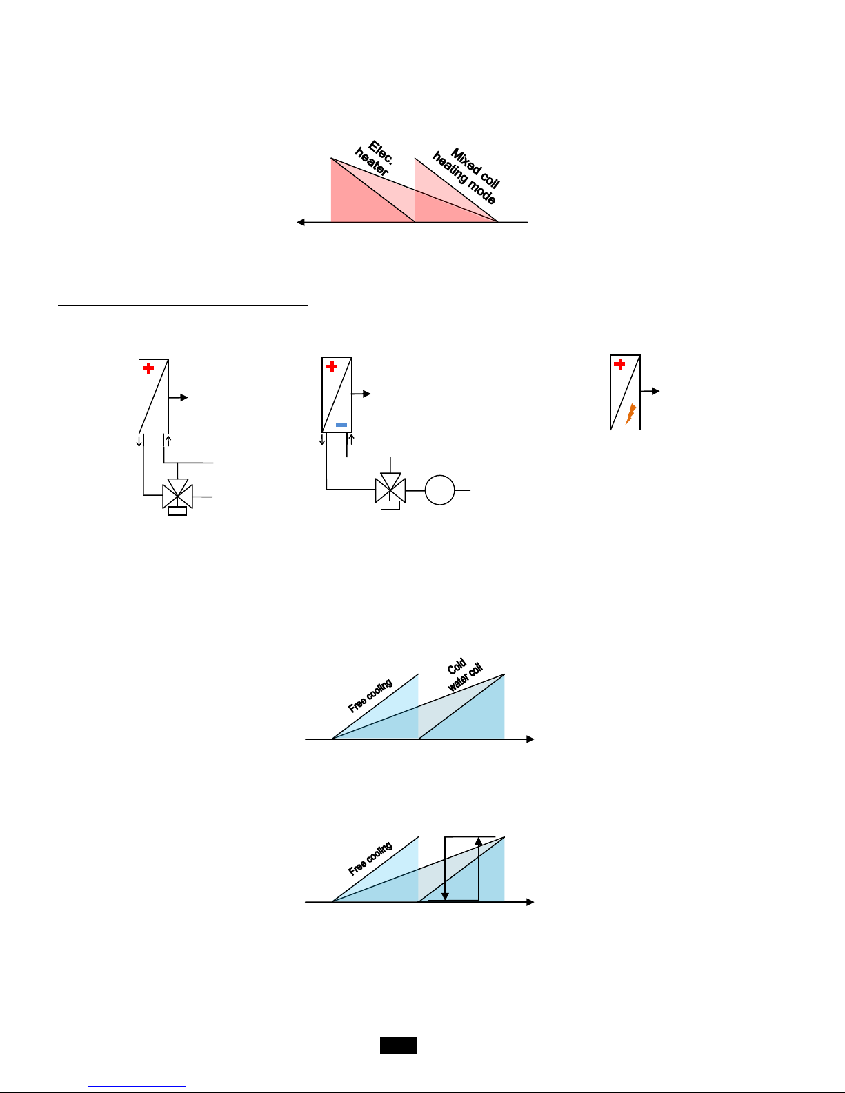
When the temperature drops, the controller will calculate the heat requirement needed to keep this temperature constant.
This gradually adjusts the output of the 2 heating coils (via a 3-way valve for coil 1, via a triac or using 1 or 2 stages in the
case of an electric heater) or a "Mixed" type in heating mode (authorised by the water network temperature sensor for coil 2
only).
The order in which the various heat generators are activated can be configured.
Coils available to meet the heating requirement s
Heating coil
Mixed water coil
Electric heater
By increasing the regulated temperature, the controller will calculate the exact cooling requirement.
If conditions permit, it will authorise Free Cooling then gradually adjust the output of the cooling coil (via a three-way valve),
"Mixed" type in cooling mode (authorised by the water network temperature sensor for coil 2 only) or DX type (direct
expansion) and will request that the condensation unit starts up when the level of demand from the coil reaches 66%
(adjustable) and that it stops when the demand is 33% (adjustable).
If Free Cooling is disabled, the requirement will be taken over by the coil.
The distribution of the requirement between the Free Cooling and the coil is adjustable.
BM
Y
B
A
B
A
T°C
S
BC
BC
B
A
B
A
Y
Heating requirement (%)
50
100
0
Cooling requirement (%)
50
100
0
Cooling requirement (%)
50
100
0
Condensation
unit for the DX
coil
66%
Page 17
17
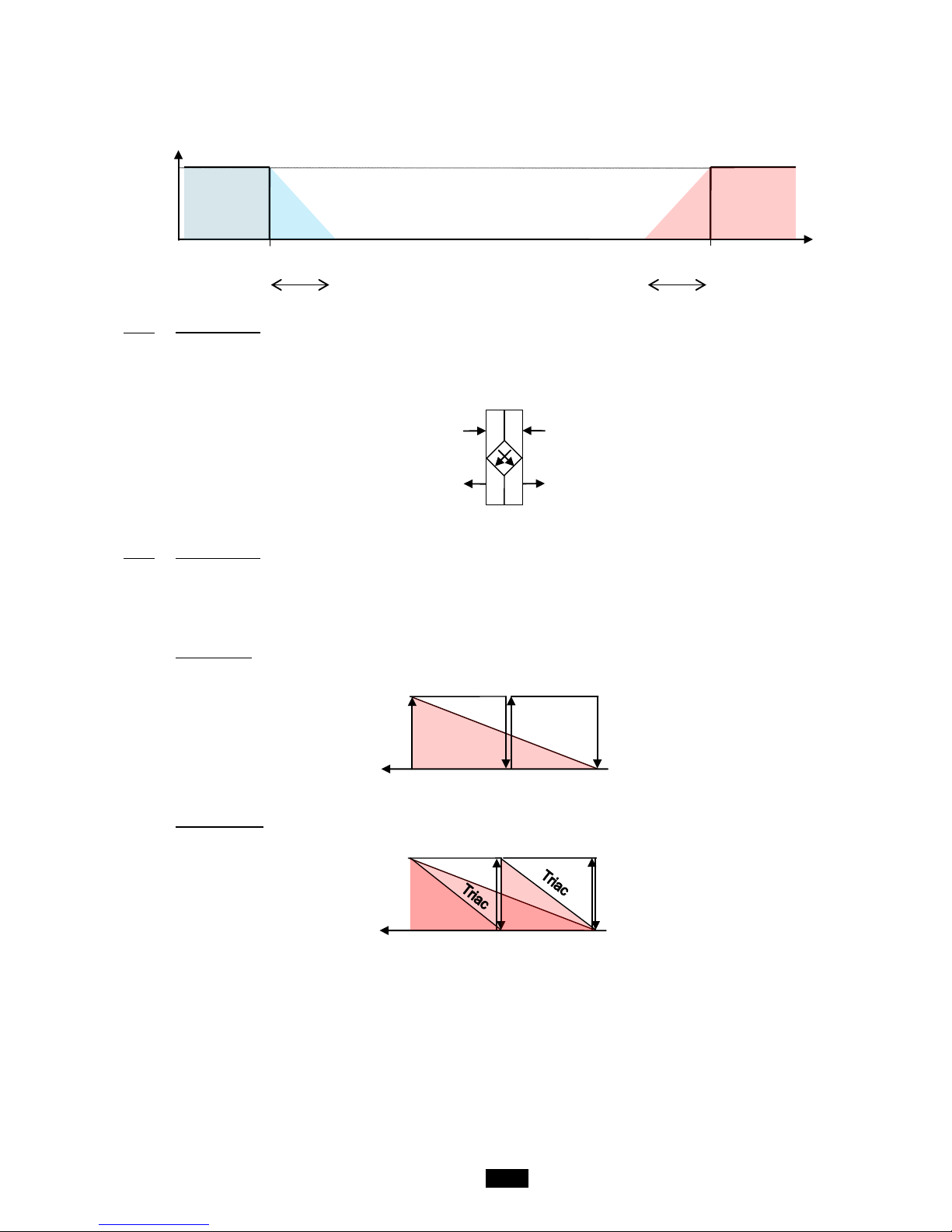
If coil 2 is configured as Mixed, the action on its valve will be limited to prevent a drift in the temperature for the return network to
the heat pump.
If there is a fault with the heat pump (information received via a potential-free (dry) contact), an alarm will be displayed.
1.6.8 Plate recovery
A differential pressure switch is used to check the fouling level on the return side of the heat recovery unit and to manage the frost
protection safety function when the unit is running. This safety function activates the bypass damper.
This damper is also activated if there is a Free cooling request.
1.6.9 Electric heater
In case of a problem on the electric heater (safety thermostats), the electric heater is shut off and the fault is signalled.
Load shedding of the electric heater via the input ID6 is available (function also available through communication with the CMS).
The aim is to use the same input ID1 to control either:
This control principle does not cause an alarm to be created.
1 or 2 stages
Triac + 1 stage
N
etwork T°
Cooling mode
authorised
10
40
Heating mod e
authorised
Cooling and heating modes
prohibited
band
band
Heating requirement (%)
Stage 2
100
0
50
Stage 1
Electric heating requirement
(%)
Stage 2
100
0
Stage 1
50
Page 18
18
1.6.10 Free cooling
The aim of this function is to make use of fresh outdoor air before starting to use the cooling coil to cool the building's supply air.
This function is only available if there is a mixing box or a plate heat exchanger equipped with a bypass damper.
Free Cooling management is based on actuating the mixing damper servomotor to alter the proportion of fresh air brought into the
building and opening the plate heat exchanger bypass, if present.
To authorise Free cooling, certain conditions must be fulfilled:
- The fresh air temperature must be below 17°C.
- The fresh air temperature must be below the return (or ambient) air temperature – 3°K
If there is a mixing damper, the percentage of fresh air depends on the cooling request sent by the regulation. A minimum value of
fresh air supply when the unit is stopped is adjustable.
1.6.11 Humidifier
Humidification of the intake air is managed via a self-contained humidifier equipped with a humidity sensor and authorised to
operate in accordance with the order given by the controller once the uni t is running at optimum levels.
A summary of faults will be sent back to the controller via a potential-free (dry) contact so an alarm is displayed.
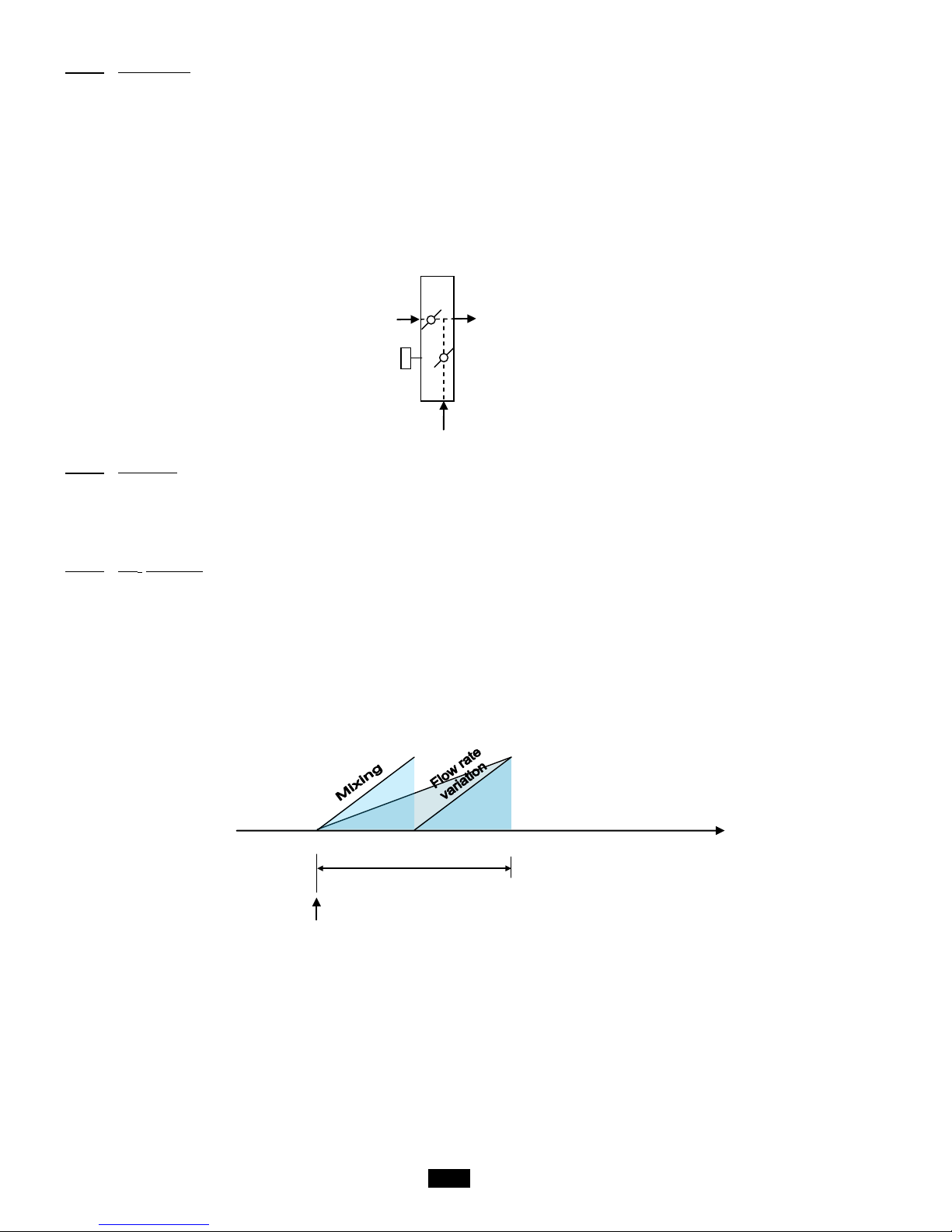
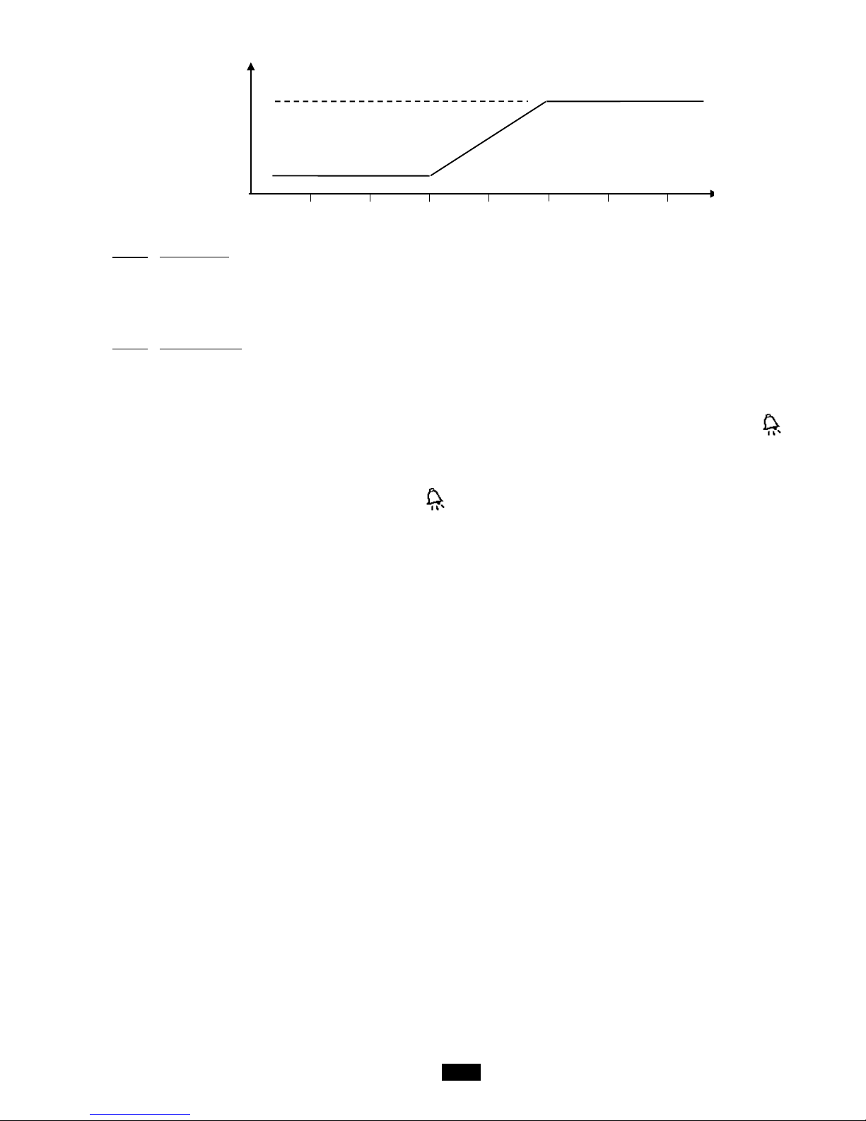
1.6.12 CO
2
air quality
The aim is to regulate the air quality, measured in ppm of CO2, using a duct sensor measuring the return flow, the measurement
range for which is 0 to 2000ppm.
There are two possible actions to manage the air quality, which can be combined:
- Either the mixing damper is managed to alter the proportion of fresh air supplied to the building
- Or the fan flow rate is varied
In the event that the two actions are selected, the controller will actuate the mixing damper, then alter the fan flow rate.
This management is incompatible with pressure regulation in the supply air duct.
SMR
ppm CO2
900
8500
800
Quality proportional band
setpoint
Page 19
19
1.6.13 Night cooling
The aim of this function is to us e the coolness of fresh air from outdoors during the night within the building, with an option of overventilation, as far as the system will allow.
This function is only available if there is a mixing box or a plate heat exchanger equipped with a bypass damper.
It is activated by a timer or the CMS, whilst the room air or return air temperature is checked against a setpoint.
1.6.14 The fault relays
1 relay per fault summary level is provided:
- "Maintenance" fault summary
- "Danger" fault summary
"Maintenance" faults are alarms which only send information to notify the operator. They can be validated by press ing the key
for 3 seconds if they have disappeared.
The "Danger" faults, which are of a higher level, are alarms which send information to notify the operator, but also start a process
to secure the unit. They can be validated by pressing the key for 3 seconds if they have disappeared, and after the unit has
been switched off.
It is possible to select the type for each fault (Danger or Maintenance), apart from for the Fire fault.
It is also possible to select the direction of ac tion for the summary relays.
0
Need for
variation (%)
100
Rated flow
Maximum flow
rate
Page 20

20
1.7 Controller inputs and outputs
G 24Vac
G0 Shared
1.7.1 Analogue inputs
Connector J3
B1 Return air temperature sensor (Option)
B2 Supply air temperature sensor
B3 Fresh air temperature sensor (Option)
B4 Network water temperature sensor (Option)
B5 Supply air filter CF1 fouling level pressure sensor
B6 Supply air fan flow rate pressure sensor (Option)
B7 Return air fan flow rate pressure sensor (Option)
GND Shared
Connector J18
B8 ---------B9 ---------B10 Return air filter CF1 fouling level pressure sensor
B11 Air quality sensor (Option)
B12 Supply air duct pressure sensor (Option)
1.7.2 Digital inputs
Connector J4
DI1 Supply air fan monitoring
DI2 Return air fan monitoring
DI3 Filter CF2 pressure switch (optional)
DI4 Frost protection thermostat (Option)
DI5 Remote control
DI6 Load shedding (Option)
DI7 Monitoring of electric heater overheating thermostat (Option)
DIC1 Shared
Connector J16
DI8 Fire (Option)
DI9 Humidifier fault summary (Option)
DI10 Heat recovery unit fouling level pressure switch (Option)
DIC2 Shared
1.7.3 Analogue outputs
Connector J5
Y1 Supply air fan speed 0-10V control
Y2 Return air fan speed 0-10V control (Option)
Y3 0-10V control for the coil 1 water valve (Option)
Y4 0-10V control for the coil 2 water valve (Option)
GND Shared
1.7.4 Digital outputs
Connector J12
NO1 ---------NO2 ---------NO3 Condensation unit On control
C1 Shared
Connector J13
NO4 Stage 1 control for the el ectric heaters
NO5 Stage 2 control for the el ectric heaters
NO6 Danger alarms summary rel ay
C2 Shared
Page 21

21
Connector J14
NO7 Maintenance alarms summary relay
C3 Shared
Connector J15
NO8 Mixing damper opening control
NO9 Mixing damper closing control
NO10 Plate heat exchanger bypass damper contr o l
NO11 Insulation damper control
NO12 Humidifier control
C4 Shared
Page 22

22
2 Overview of the HMI module screens
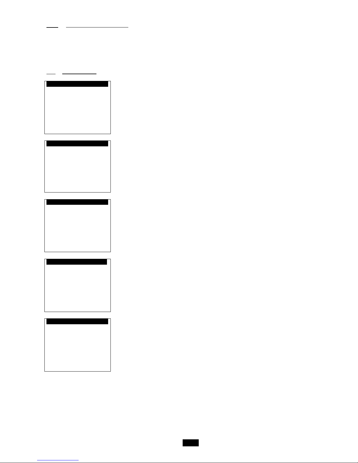
2.1 Esc button
"Prg" button
U :01 00:00
00.0°c
Off
U:01 Indicates the unit's address
Indicates the request to switch the machine on or off
00.0°C Indicates the controlled temperature (ambient, exhaust or intake)
00:00 Indicates the time
Off Indicates the state of the unit: on, off, on after a power failure, standby, switched off by a fault, switched off by CMS,
post ventilation, manual mode
Indicates "Heating" operating mode
Indicates the "Cooling" operating mode
Indicates Fire al arm
Indicates the operation of the fan(s)
"Prg" button
Menu
14.Access level
16.Vers ions
1.Setpoints
2.Machine status
4. Machine parameters
To switch to another menu, press the or buttons to scroll through the available menus. The selected menu is opposite the arrow and on a
black background. To confirm your choice, simply press enter or .
The available menus are as follows:
- 1. Setpoints
- 2. Machine status
- 4. Mac hi ne param eters
- 5. Adjustment parameters
- 6. Readi ng param eters
- 7. Fault memory
- 8. Test mode
- 9. T imer prog.
- 11. Communication
- 12. Alarm s
- 14. Access levels
- 16. Versions
Page 23
23
2.1.1 Access level selection menu
There are now three access levels:
- Level 1: User
- Level 2: Installer
- Level 3: Manufacturer
2.2 Setpoint menu
Comfort w0
Indication of the operating mode. Level 2 access
Fan flow rate
Supply air 02000m3/h
Supply air fan Comfort flow rate control setpoint
Return air 02000m 3/ h
Return air fan Comfort flow rate control setpoint
Eco
Supply air 01000m3/h
Supply air fan Eco flow control setpoint
Return air 01000m3/h
Return air fan Eco flow control setpoint
Comfort w1
Indication of the operating mode. Level 2 access
Duct pressure
200Pa
Comfort pressure control setpoint for the Supply air duct
Eco 100Pa
Eco pressure control setpoint for the Supply air duct
Comfort w2
Indication of the operating mode for T° regulation in "Precision" mode Level 1 access
Return air 20.0°c
Comfort (Return or Ambient air) temperature control setpoint monitored (0 to 50.0°C)
Eco 15.0°c
Eco (Return or Ambient air) temperature control setpoint monitored (0 to 50.0°C)
Supply air
Upper limit 26.0°c
Upper limit for calculated Supply air T° setpoint
Lower limit 16.0°c
Lower limit for calculated Supply air T° setpoint
w3
Level 2 access
Air quality
0800ppm CO2
Air quality control setpoint
Maximum flow rate
03000m3/h
Maximum flow rate value of supply air fan for air quality control
Comfort w4
Indication of the operating mode for T° regulation in "Energy optimisation" mode Level 1 access
Return air Cooling 25.0°c
Comfort Cooling (Return, Ambient or Supply air) temperature control setpoint monitored (0 to 50.0°C)
Eco 27.0°c
Eco Cooling (Return, Ambient or Supply air) temperature control setpoint monitored (0 to 50.0°C)
Return air Heating 23.0°c
Comfort Cooling (Return, Ambient or Supply air) temperature control setpoint monitored (0 to 50.0°C)
Eco 18.0°c
Eco Cooling (Return, Ambient or Supply air) temperature control setpoint monitored (0 to 50.0°C)
Deadband
Indication of the control state for the monitored temperature
Page 24
24
Comfort w5
Indication of the operating mode for T° regulation in "Energy optimisation" mode Level 1 access
Supply air Cooling 16.0°c
Cooling Comfort Supply air temperature control setpoint (Regulated T° ≠ Supply air) (0 to 50.0°C)
Eco 18.0°c
Cooling Eco Supply air temperature control setpoint (Regulated T° ≠ Supply air) (0 to 50.0°C)
Supply air Heating 26.0°c
Heating Comfort Supply air temperature control setpoint (Regulated T° ≠ Supply air) (0 to 50.0°C)
Eco 24.0°c
Heating Eco Supply air temperature control setpoint (Regulated T° ≠ Supply air) (0 to 50.0°C)
U :01 w6
Level 2 access
Frost protection 17.0°c
Unit reactivation setpoint in "Standby" mode when there is an ambient temperature sensor
w7
Level 2 access
Night cooling 17.0°c
Control setpoint in "Night cooling" mode
Duct 200Pa
Supply air duct pressure control setpoint for night cooling
Supply air 02000m3/h
Supply air fan Comfort flow rate control setpoint for night cooling
Return air 02000m3/h
Return air fan Comfort flow rate control setpoint for night cooling
w8
Level 3 access
Electric heater
Off On
Stage 1 000.0% 050.0%
Stage 1 on and off setpoint for the electric heater
Stage 2 050.0% 066.6%
Stage 2 on and off setpoint for the electric heater
w10
Free cooling 17.0°c
Outdoor temperature limit value for authorisation of free cooling (Level 3 Access)
Min fresh air ctrl 000%
Fresh air minimum value (Level 2 Access)
w12
Level 3 access
Min. th-Tune setpoint
15.0°c
Min. temperature setpoint value regulated via the room terminal
Max. th-Tune setpoint
30.0°c
Max. temperature setpoint value regulated via the room terminal
Page 25

25
w13
Level 2 access
Filter CF1
Filter dirty 0250Pa
Dirty supply air filter 1 saturation level detection setpoint
Filter clogged 0400Pa
Blocked supply air filter 1 saturation level detection setpoint
w16
Level 3 access
DX coil
Off On
State 033.3% 066.6%
DX coil on and off setpoint
w17
Level 3 access
Changeover
Heating 40.0°c
Changeover limit setpoint value in Heating mode and water return temperature
Cooling 10.0°c
Changeover limit setpoint value in Cooling mode and water return temperature
Band limit 02.0°c
Value for the water return temperature control proportional band
U :01 w18
Level 3 access
Checking duct
pressure sensor
Low threshold 10Pa
Intake duct pressure low threshold
High threshold 900Pa
Intake duct pressure high threshold
2.3 Machine parameters menu
This menu is Level 3 access
Fault type d1
Level 2 access This screen is used to configure the criticality of the faults managed by the regulating controller.
M=Maintenance D=Danger
If a fault is shown as "Danger" the unit will be shut off. If the fault is shown as "Maintenance", only an alarm
message will be given.
0 1 2 3 4 5 6 7 8 9
0x D D M D M D M M D
Criticality of faults 1 to 9
1x
D M M M M M D M
Criticality of faults 10 to 19
2x
3x
Page 26
26
See appended table
List of faults:
Order
Description
Significance
01
Supply air motor
Danger
02
Return air motor
Danger
03
Supply air filter dirty
Maintenance
04
Supply air filter clogged
Danger
05
Return air filter CF1 dirty
Maintenance
06
Return air filter CF1 clogged
Danger
07
Filter CF2 dirty
Maintenance
08
Humidifier
Maintenance
09
Heat recovery unit frosted – Clogging detection
Danger
10
Antifreeze protection
Danger
11
Electric heater safety thermostat
Maintenance
12
Low supply air temperature
Maintenance
13
High supply air temperature
Maintenance
14
Low room or return air temperature
Maintenance
15
High room or return air temperature
Maintenance
16
Duct pressure sensor
Danger
17
Clock lithium battery
Maintenance
Configuration c0
Level 3 access
Unit size:
----
Type of unit:
---- / ---- / ----
Unit size: ---, 25, 40 1V, 40 2V, 60
Type of unit: Special boxes/Main box/R e tur n air box
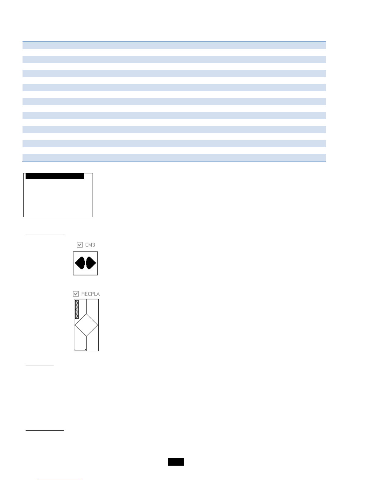
1. Special boxes:
- CM3: 3-way mixer
- PLA: plate heat exchanger
2. Main box:
- F: Filter (always in 1st position)
- F2: 2 Filters
- V: Fan
- C: Hydraulic heating coil
- E: 2-stage electric heating coil
- T: Triac electric heating coil + 1 stage
- F: Hydraulic cooling coil
- M: Mixed hydraulic coil
- X: DX cooling coil (direct expansion)
3. Return air box
The flow of return air cannot be FV only.
Page 27
27
Configuration c1
Level 3 access
Filter CF2 ----
Presence of a second filter at the inlet
Return air unit ----
Filter CF2 : Without, With
Return air unit: Without, With
Configuration c2
Level 3 access
Heating coil ----
Cooling coil ----
Electric heater
----
Heating coil:
- Without: No coil
- Hydro: Hot water coil
- Elec: Electric heater
Cooling coil:
- Without: No coil
- Hydro: Cold water coil
- DX: Refrigerant fluid direct expansion coil
- Mixed: Cold or hot water coil monitored by a network water T° sensor
Electric heater:
- Without: No electric heater
- 2-stage + On/Off: 2-stage on/off electric heater
- On/Off + Triac: 1-stage On/Off or 1-stage Triac electric heater
Configuration c3
Level 3 access
Heat recovery unit ----
Damper ----
Mixing ----
Heat recovery unit : Without, With
Damper: Without, With
Mixing: Without, With
Th. Antifreeze protection: Without, With
th-Tune: Without, With
Control priority: Precision or Energy optimisation mode
Configuration c5
Level 3 access
Humidifier ----
Humidifier: Without, With
Configuration c4
Level 3 access
Frost protection th. ----
th-Tune ----
Control priority
--
Page 28

28
Configuration c6
Level 3 access
Supply air fan
K = -----
Return air fan
K = -----
Supply air fan: K coefficient values for the Supply air fan
Return air fan: K coefficient values for the Return air fan
2.4 Adjustment parameters menu
lg
Level 1 access
Language ------------
Controller language selection (French)
t0
Level 1 access
Setting
of the clock
Time -- :--
Clock time correction value
Date --/--/--
Clock date correction value
Supply air p1
Level 2 access
Cooling DB 00.0
Deadband value for Supply air temperature control in cooling mode
CLG band 0005.0
Proportional band for Supply air temperature control in cooling mode
T I 0150s T D 0000s
Integral time and derivative time for Supply air temperature control in cooling mode
Heating DB 00.0
Deadband value for Supply air temperature control in heating mode
HTG band 0005.0
Proportional band for Supply air temperature control in heating mode
T I 0150s T D 0000s
Integral time and derivative time for Supply air temperature control in heating mode
Return air p2
Level 2 access
Differential
Value for the Return or Ambient air temperature control differentials
Cooling Heating
In cooling mode In heating mode
0.0 0.0
p3
Level 2 access
Fan management
--------
Free Cooling ----
Fire ----
Fan management: Without, Flow rate (constant flows and independent setpoints) or Pressure (Constant supply air duct pressure
and identical fan speed values)
Free Cooling: Without, With
Fire: Without, With
Page 29
29
p4
Level 2 access
Regulated T° ----
Air quality -----
M factor 01.0
Proportionality factor value for Supply air duct flow rate and pressure control
Quality band 100
Air quality regulation proportional band
Regulated T°: Supply, Return or Ambient air
Air quality: Without, With (not available if the fans are monitored based on constant Supply air duct pressure)
Supply air p5
Level 2 access
High T shift 05.0
High supply air temperature threshold shift
Low T shift -05.0
Low supply air temperature threshold shift
Shutdown valve 1 open 000%
Opening value for the valve for heating coil 1 when the supply air ventilation is stopped
Shutdown valve 2 open 000%
Opening value for the valve for heating coil 2 when the supply air ventilation is stopped
Return air p6
Level 2 access
High T shift 05.0
High return (or ambient) air temperature threshold shift
Low T shift -05.0
Low return (or ambient) air temperature threshold shift
p14
Level 3 access
Fans
Supply air
Band 1200.0
Supply air fan flow rate control proportional band
T I 0010s T D 0000s
Integral time and derivative time for supply air fan flow rate control
Return air
Band 1200.0
Return air fan flow rate control proportional band
T I 0010s T D 0000s
Integral time and derivative time for return air fan flow rate control
p15
Level 3 access
Duct
Band 0595.0
Duct pressure control proportional band
T I 0004s T D 0001s
Integral time and derivative time for duct pressure
p16
Level 3 access
Supply air limits
Supply air T° setpoint calculation parameters (See the first figure on page 14)
X1 offset -5.0°c
X1 shift value for the formula for calculating the supply air temperature Comfort setpoint
Eco -7.0°c
X1 shift value for the formula for calculating the supply air temperature Eco setpoint
X2 offset 5.0°c
X2 shift value for the formula for calculating the supply air temperature Comfort setpoint
Eco 7.0°c
X2 shift value for the formula for calculating the supply air temperature Eco setpoint
Page 30
30
p17
Level 3 access
FC offset -3.0°c
Outdoor T° offset from regulated T° for Free Cooling authorisation
Prioritisation p18
Level 3 access
heating coils
Start End
Coil 1 ---.- ---.-
Coil 1 actuation start and end setpoint value
Coil 2 ---.- ---.-
Coil 2 actuation start and end setpoint value
p19
Level 3 access
Coil distribution
Electric with triac
Stage 2 050.0%
Setpoint value for the electric heater stage 2 actuation start
p20
Level 3 access
Air quality
Quality band 100
Air quality regulation proportional band
Calibration ca1
Level 3 access
Return air 00.0°c
Calibration of the regulated temperature sensor (return or room)
Supply air 00.0°c
Calibration of the supply air temperature sensor
Fresh air 00.0°c
Calibration of the fresh air temperature sensor
Water network 00. 0°c
Calibration of network water temperature sensor
Calibration cam
Level 3 access -> Accessible by pressing the Prg key from the mask ca1
Pressure sensor calibration
NO
Manual calibration of pressure sensors. Warning: the fans must be completely stopped before using this function.
Calibration ca2
Level 3 access
Air quality 000ppm
Calibration of air quality sensor
Page 31

31
Input direction se1
Level 3 access
Supply air fan control NC
Direction of the supply air fan sensor information during operation
Antifreeze thermostat NO
Direction of the antifreeze thermostat control information during operation
CF2 pressure switch NC
Direction of the filter CF2 pressure switch control information during operation
Fire sensor NC
Direction of the fire sensor control information during operation
Elec heater safety NC
Direction of the electric heater control information during operation
Remote control NC
Direction of the control information for the remote control when "On"
Input direction se2
Level 3 access
Return air fan control NC
Direction of the return air fan sensor information during operation
Elec heater load shedding NO
Direction of the electric heater "load shedding" check information
Humidif. check NC
Direction of the humidifier check information during operation
Exch. pressure switch NC
Direction of the plate heat exchanger pressure switch control information during operation
Output direction ss1
Level 3 access
Danger NC
Controller contact state when there are no "Danger" faults (NO or NC)
Maintenance NC
Controller contact state when there are no "Maintenance" faults (NO or NC)
2.5 Read-only parameters menu
2.5.1 Inputs
i0
Level 1 access
Supply air --.-°c
Supply air temperature value
Return --.-°c
Controlled temperature value (return or ambient )
Fresh air --.-°c
Fresh air temperature value
Water network --.-°c
Network water temperature value
i1
Level 1 access
Fan flow rate
Supply air ------m3/h
Supply air fan flow rate value
Return air ------m3/h
Return air fan flow rate value
Duct pressure ----Pa
Supply air duct pressure value
i2
Level 1 access
Filters
CF1 ----Pa
Supply air CF1 filter fouling value
CF1 Return ----Pa
Return air filter CF1 fouling value
Pressure switch CF2 -
Additional filter CF2 fouling pressure switch state
Air quality ----ppm
CO2 air quality value
Page 32

32
i3
Level 1 access
Supply air fan -
Supply air fan operation check state (C = on; O = off)
Return air fan -
Return air fan operation check state (C = on; O = off)
Fire -
Fire detection sensor check state (F = no fire; O = fire detected)
i4
Level 1 access
Humidif. check -
Humidifier check state (C = no faults; O = fault detected)
Elec heater load shedding -
Load shedding command state (C = Load shedding; O = No load shedding)
Remote control -
Remote control state (F = on; O = off)
i5
Level 1 access
Elec. heater safety -
State of electric heater safety thermostat (C = fault detected; O = no faults)
Antifreeze thermostat -
Frost protection thermostat state (C = fault detected; O = no faults)
Exch. pressure switch -
Plate heat exchanger pressure switch state (C = fault detected, O = no faults)
2.5.2 Outputs
o1
Level 1 access
Fan ---%
Supply air fan variable frequency drive control value
Return air fan ---%
Return air fan variable frequency drive control value
Coil 1 Heating ---%
Water coil 1 valve control value (Heating or Triac)
Coil 2 Cooling ---%
Water coil No.2 valve control value in "Cooling" mode (or Heating)
o2
Level 1 access
Recov. bypass ---
Plate heat exchanger bypass damper control state
o3
Level 1 access
Danger -
"Danger" fault summary relay state
Maintenance -
"Maintenance" fault summary relay state
Page 33

33
o4
Level 1 access
Damper ---
Damper control state (frost protection or insulation)
Electric heater
Stage 1 ---
Electric heater stage 1 control state
Stage 2 ---
Electric heater stage 2 control state
o5
Level 1 access
DX module ---
DX module control state
Humidifier ---
Humidifier operation authorisation state
o6
Mixing ---%
Mixing damper opening value
Control -
Mixing damper control state ( = opened; = closed)
2.5.3 Calculated setpoints
wc1
Calculated --.-°c
Control setpoint calculated for the Supply air temperature when the regulated temperature is
Return or Room
2.5.4 Counters
Counters tt1
Supply air fan
-----h Reset-
Supply air fan runtime counter reset and time
Counters tt2
Return air fan
-----h Reset-
Return air fan runtime counter reset and time
Page 34
34
Counters tt3
Electric heater
Stage 1 -----h Reset -
Electric heater stage 1 runtime counter reset and time
Stage 2 -----h Reset -
Electric heater stage 2 runtime counter reset and time
Counters tt4
Humidifier
-----h Reset-
Humidifier runtime counter reset and time
Counters tt5
DX module
-----h Reset-
DX module runtime counter reset and time
Counters tt6
Bypass
-----h Reset-
Plate heat exchanger bypass servomotor runtime counter reset and time
2.6 Fault memory menu
Log H000
Alarm
00 :00 00/00/00
H000 Indicates the log number for the alarm
00/00/00 Indicates the date of the alarm
00:00 Indicates the time of the alarm
Alarm Indicates the alarm
"Prg" button
Level 3 access
Reset Reset the alarm log
RH
Reset No
Page 35

35
2.7 Versions menu
U :01 PROGRAM pr1
AirCompact Control
V 02.00 09/03/15
Bios: 06.08
Boot: 04.05
Indicates the reference of the program installed on the controller, the controller version and pLAN address.
U :01 PROGRAM pr2
SO: --------
Order number for the unit
El box: --------
Serial number for the unit electrics box
2.8 Time schedule menu
If the unit is configured to be switched on by the CMS (Unit control = With), the menu of time schedules is not accessible and this
screen appears:
Time schedules .
Functions carried out
By the CMS
Otherwise:
Day1
→
Day2
→
Day3
→
Day4
Period 00:00 → 00:00
Period 00:00 → 00:00
Period 00:00 → 00:00
Period 00:00 → 00:00
State:
State:
State:
State:
---------------------
---------------------
---------------------
---------------------
Period 00:00 → 00:00 Start and end times (hour and minute) of daily time program period
State: Selection of the state during this period: ----- Eco T°
Comfort T°
Eco flow rate
Comfort flow rate
Eco pressure
Comfort pressure
Standby
Cool night
Page 36

36
Week1
→
Week2
→
Week3
→
Week4
Period 00:00 → 00:00
Period 00:00 → 00:00
Period 00:00 → 00:00
Period 00:00 → 00:00
State:
State:
State:
State:
---------------------
---------------------
---------------------
---------------------
□Sunday □Monday
□Sunday □Monday
□Sunday □Monday
□Sunday □Monday
□Tuesday □Wednesday
□Tuesday □Wednesday
□Tuesday □Wednesday
□Tuesday □Wednesday
□Thursday □Friday
□Thursday □Friday
□Thursday □Friday
□Thursday □Friday
□Saturday
□Saturday
□Saturday
□Saturday
Period 00:00 → 00:00 Start and end times (hour and minute) of weekly time program period
State: Selection of the state during this period: ------
Eco T°
Comfort T°
Eco flow rate
Comfort flow rate
Eco pressure
Comfort pressure
Standby
Cool night
□Sunday
□Monday
□Tuesday
□Wednesday Day of the week on which the weekly time program is applied (■= day selected)
□Thursday
□Friday
□Saturday
Annual1
→
Annual2
→
Annual3
→
Annual4
Period 00:00 → 00:00
Period 00:00 → 00:00
Period 00:00 → 00:00
Period 00:00 → 00:00
State:
State:
State:
State:
---------------------
---------------------
---------------------
---------------------
Date 00/00/2000
Date 00/00/2000
Date 00/00/2000
Date 00/00/2000
Period 00:00 → 00:00 Start and end times (hour and minute) of annual time program period
State: Selection of the state during this period: ----- Eco T°
Comfort T°
Eco flow rate
Comfort flow rate
Eco pressure
Comfort pressure
Standby
Cool night
Date 00/00/2000 Day, month and year of yearly time program
Access to the following group of screens via the Prg button is protected by level 3 access
t1
Fan delay 060s
post ventilation time
Battery reset N
Reset the Lithium battery replacement indicator
Damper 180s
Total opening time for complete damper
Mixing damper 150s
Opening time value for the mixing damper servomotor
Defrost 150s
Minimum opening time value for plate heat exchanger defrost
Page 37
37
Timer t2
Daylight Saving Time and Standard Time switchover management activated
Summer/Winter: ACTIVE
Transit. time 060min
Start:LAST SUNDAY
in MARCH at 02.00
End:LAST SUNDAY
in OCTOBER at 03.00
2.9 Communication menu
SUPERVISION g1
Level 3 access
Protocol -----------
Choice of the communication protocol with the CMS (CAREL, LON, MODBUS RTU, KNX, WEB, MODBUS TCP)
Speed ----- bauds
Selection of the speed of communication with the CMS (4800 mandatory for LonWorks)
Address ---
Address of the controller on the network for communication with the CMS (001 mandatory for LonWorks)
Unit control ----
Selection of the On/Off control via the CMS
pLAN NETWORK pL1
Controller address 01
Address of the controller on the pLAN communication network to the user terminal
pLAN network state
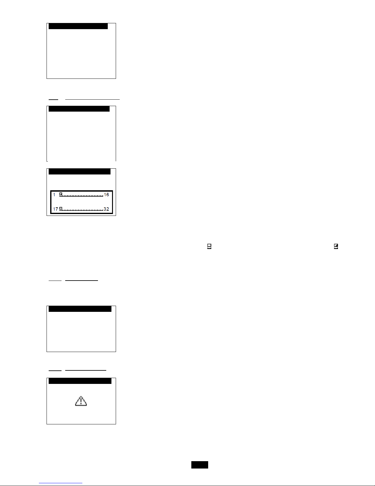
When the system starts up, the pLAN network may encounter a number of problems (card fault and terminal start-up) caused by
incorrect connections or a wrong address. The state of the pLAN network can be displayed in real time on this special mask in
order to identify whi c h devices (controller or terminal) are correctly connected and addressed.
Network addresses 1 to 32 are displayed. The small rectangles represent the terminals and the large rectangles , the
controllers.
If the symbols flash, the pLAN may be unstable or, more likely , two component s share the s ame address.
The example indicates that the network is formed of 1 controller wi th the address 1 and 1 terminal with the address 17.
2.10 Alarms menu
Pressing the button confirms and clears all faults that are no longer present.
To view faults that are still present, press the buttons
The following screen appears when no faults are present:
.
No alarm s!
2.11 Test mode menu
f1
Overriding the outputs
Unit off
Page 38
38
If all the controller's outputs are overridden, the alarms will not be signalled on the door of the electrical box or on the display.
Disconnecting the display will maintain the override and may result in damage to the hardware.
This menu can only be accessed in level 3 and with the unit off.
WARNING!
ACTIVATION OF ALL OVERRIDES IS THE PROGRAMMER'S RESPONSIBILITY
NONE OF THE SAFETY DEVICES IS OPERATIONAL
The unit must be set to " ".
Select the unit to be changed by pressing the button or the button. Confirm by pressing ENTER.
The cursor places itself below the override authorisation (free or overridden). Confirm by pressing ENTER.
The cursor places itself under the override value. Display the new value by pressing the button or the button. Confirm by
pressing ENTER.
The unit is now in "manual mode".
The overrides are cancelled when the unit is set back to "on"
Fans f2
--------
Supply air………..………… --
Return air...………..…...…… --
Damper .
--------
Control state..……………… --
Fault relay f3
--------
Danger...………..…………… --
Maintenance…………...…… --
Valves f4
--------
Coil 1....……..……….….. ---%
Coil 2....……..…………... ---%
DX module...…………..…… --
Electric heater .
Stage 1…..……………..…… --
Stage 2………………….…… --
Mixing f5
--------
Opening.……………..……… -
Closing….………….....…… -
State……......……..……... ---%
Bypass f6
--------
Control state..……………… --
Humidifier .
Control state..…………….… --
Page 39
39
2.12 Access level menu
Access levels .
Current level: 1
Displays the current level
Access level 1 ->
Visible only if the current level = 2 or 3, used to access or return to level 1
Level 2 access
Visible only if the current level = 1 or 3, used to access or return to level 2
Level 3 access
Visible only if the current level = 1 or 2, used to access or return to level 3
Access levels .
If level 1 acce ss selected
LEVEL 1 ACCESS
Back to level 1:
No
If yes back to access level 1
Access levels .
If access level 2 selected and access level = 1
LEVEL 2 ACCESS
Password: 0000
Re-enter the installer password
Access levels .
If password ok
LEVEL 2 ACCESS
Enter new code
level 2?
No
If yes, change the installer password; if no, back to current access level page
Access levels .
LEVEL 2 ACCESS
New password:
0000
Re-enter the new installer password
Access levels .
If access level 2 selected and access level = 3
LEVEL 2 ACCESS
Back to level 2:
No
If yes back to access level 2
Access levels .
If access level 2 selected and access level = 1
LEVEL 3 ACCESS
Password: 0000
Re-enter the manufacturer password
The level 2 password can be reset to the factory value. To do this, go to level 2 access and press the "Prg" button for 10 seconds.
Page 40

40
2.13 Master/Slave menu
The Master/Slave function is used to manage several units (maximum of 8) supplying air to the same room and providing
automatic weekly rotation (168 hours). This is done to ensure uniform wearing of the AHUs.
A backup/additional function is also available.
m0
Additional ----
Unit within network ----
Additional: Without, With (Authorisation of the Additional function for the rotation of the units)
Unit within network: Without, With (Authorisation of "autonomous" operation after break with bus or absence of power for rotating
the units)
m1
Only on the unit whose address is '1'.
Unit rotation
U1: -
U2: -
U3: -
U4: -
U5: -
U6: -
U1: With rotation (unit linked and integrated into a rotation loop), Without rotation (unit linked and outside of the rotation loop), Not
present (unit not linked and outside of the rotati on loop)
U2: With rotation, Without rotation, Not present
U3: With rotation, Without rotation, Not present
U4: With rotation, Without rotation, Not present
U5: With rotation, Without rotation, Not present
U6: With rotation, Without rotation, Not present
m2
Only on the unit whose address is '1'.
U7: -
U8: -
Unit(s) on standby -
1 rotation per 168h
U7: With rotation, Without rotation, Not present
U8: With rotation, Without rotation, Not present
Unit(s) on standby : 1 to 7 (according to the total number of units linked and integrated into a rotation loop – 1)
1 rotation per : 0 to 999h (when the value 0 is applied, this allows the rotation to be checked as it will be carried out every 5
minutes)
3 Managing a network of controllers
The pLAN network is the name of the physical network that links controllers to remote HMI terminals.
pLAN = personal Local Area Network
The connection of the controllers via the pLAN network allows the datapoints of one controller to be exchanged for another,
following the logic set out by the program, i.e. the direction that these datapoints must follow and that from which they come. As a
consequence, they are not programmed by the user, who must only carry out the electrical connection.
3.1 pLAN electrical connections
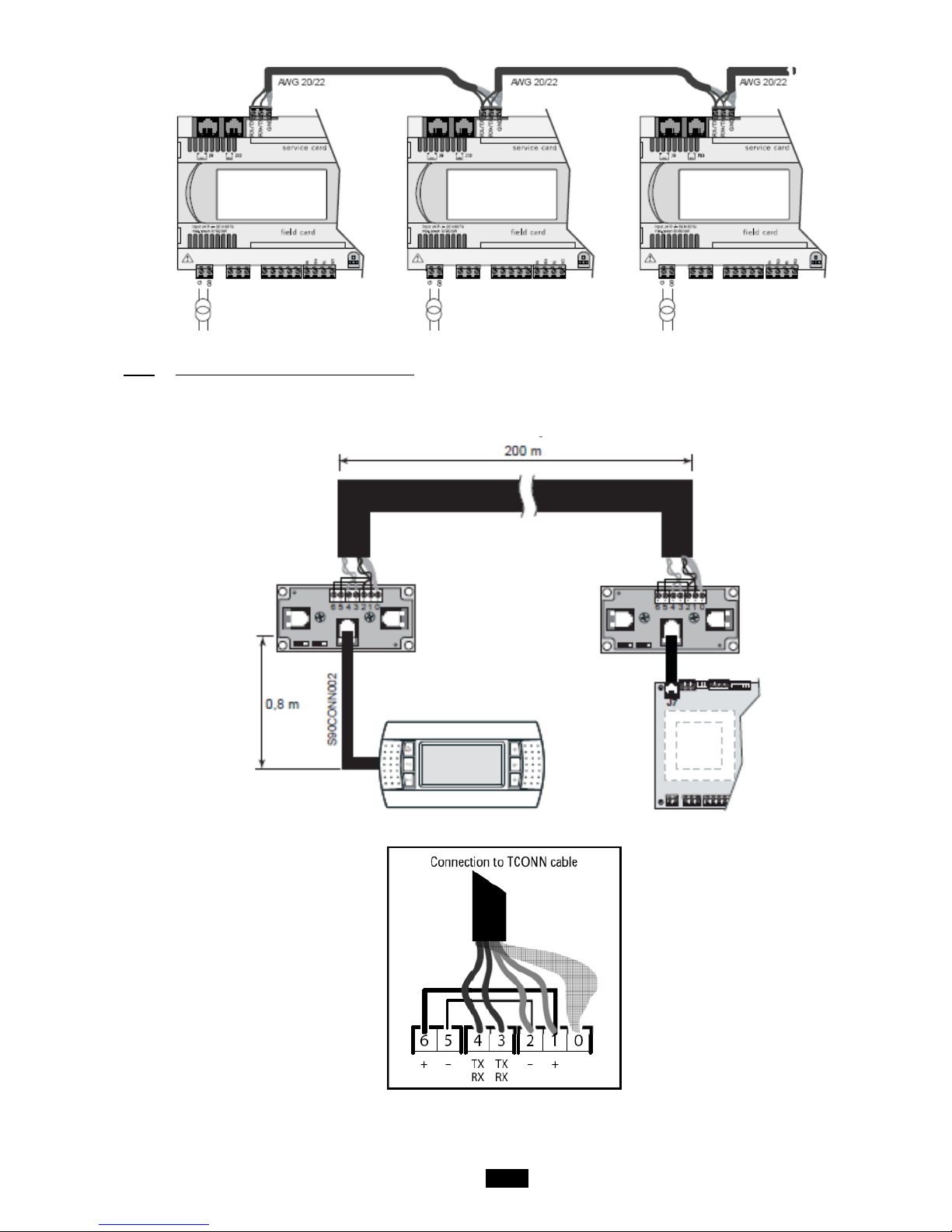
3.1.1 Connecting controllers to the pLAN
The electrical connection between the controllers under the pLAN network (RS485) is carried out using an AW G20/22 shielded
cable composed of a twisted pair and a shield. The cards must be connected in parallel using the J11 connector.
The first and last controller must be no more than 500m apart.
Page 41
41
3.1.2 Connecting a remote screen to the pLAN
A remote user terminal can be connected to each controller on the pLAN network (RS485) using two cards (CIAT code: 7122917)
and one shielded cable consisting of three AWG24 twisted pai rs and a shield.
The shielded cable must be no longer than 200m.
Page 42
42
3.2 Addressing the pLAN
Once the controllers are connected over the pLAN network, the controllers and the terminals must be addressed.
There is a range of 32 possible addresses (binary logic). As a result, a total of 32 controllers and terminals can be connected over
the pLAN network.
The pLAN network will not work if the same address is shared by two components!
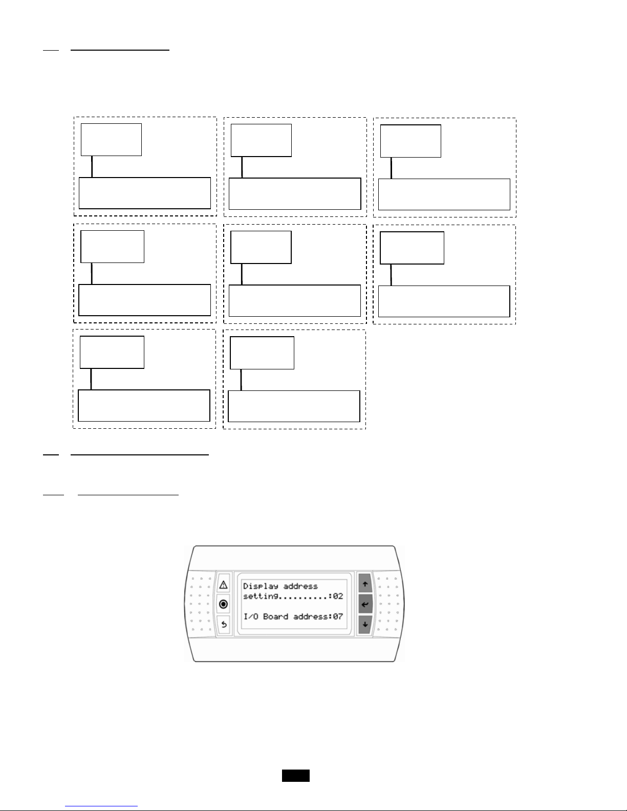
The controllers and displays must be addressed as illustrated below:
3.3 Changing the controller address
The controller pLAN address can be changed, when creating a rotation loop, in page pL1 of the Parameters menu, following the
diagram shown above.
3.3.1 Addressing the HMI terminals
The value of the factory-set address is '17'.
In order to be able to configure the terminal's address, it must first be powered via the telephone connector.
To enter configuration mode, press and buttons and (even if the terminal is already on) simultaneously for at least five
seconds. The mask of the s creen below appears and the pointer flashes at the top left corner:
• to change the terminal's address (display address setting) press the button once. The pointer will move to the address field
(02).
Display
Address 17
Controller
Unit 1
Display
Address 18
Controller
Unit 2
Display
Address 19
Controller
Unit 3
Display
Address 20
Controller
Unit 4
Display
Address 21
Controller
Unit 5
Display
Address 22
Controller
Unit 6
Display
Address 23
Controller
Unit 7
Display
Address 24
Controller
Unit 8
Page 43
43
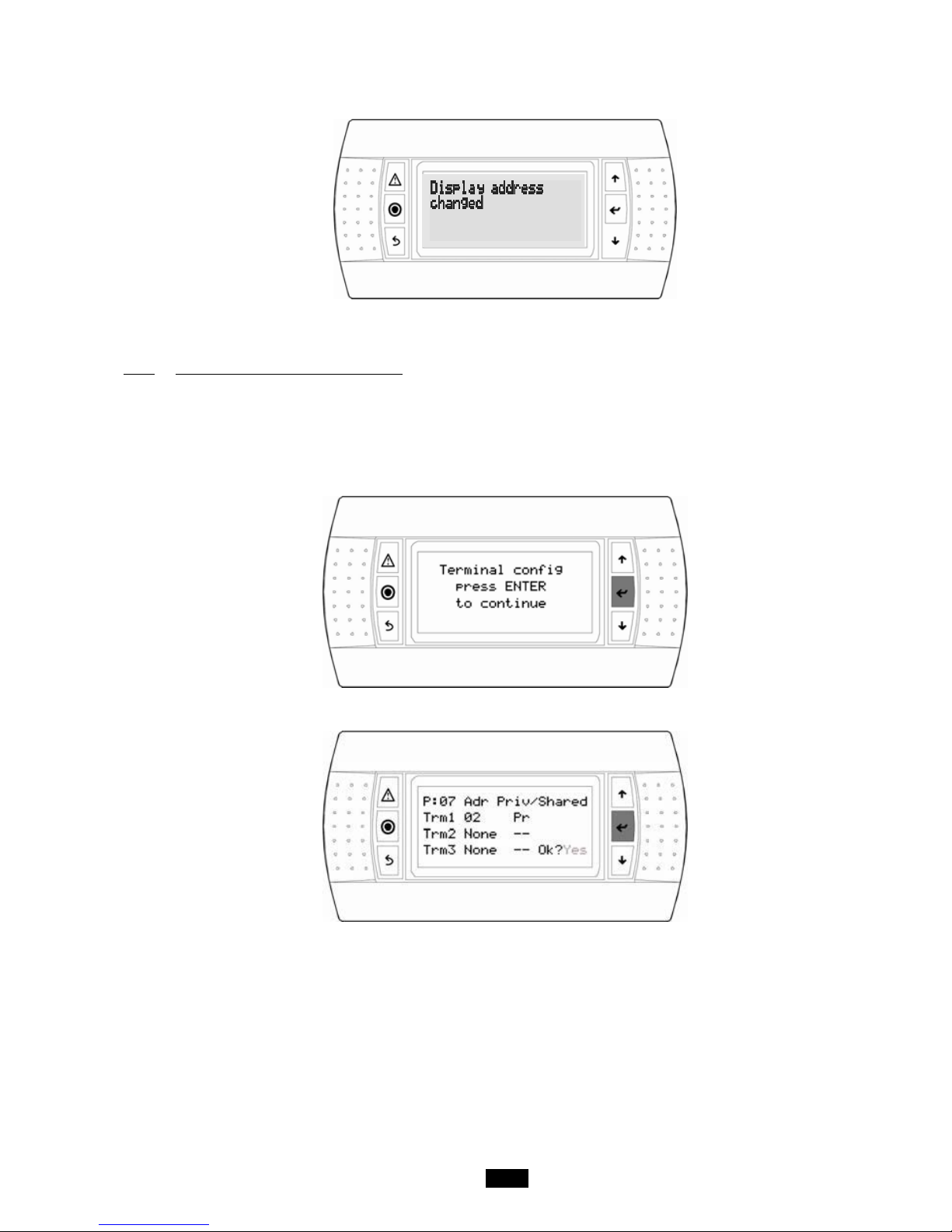
• select th e desired value usi ng the buttons and confirm by pressing the button. If the value selected is different from that
previously stored in memory, the mask of the screen below will appear and the new value will be stored in the display's permanent
memory.
If the nn field is set to '0', the terminal will use the Point-to-Point Protocol (not the pLAN) to communicate with the controller and the
“I/O Board address: 07” field will disappear as it will not be necessary.
3.3.2 Assigning private and shared terminals
Follow the procedure below if, at this point, it is necessary to change the list of terminals associated with each controller:
• enter configuration mode by pressing the and buttons as described in the previous section;
• press enter until the pointer moves to the "I/O board address" fiel d;
• using the buttons, select the address of the desired controller. The only values selectabl e will be those of the controll ers that
are on the network. If the pLAN network is not working correctly or if no controllers are present, the field cannot be changed and
will display a “—”;
• press the enter button once more. the following mask sequences will be displayed:
• as above, press enter to move the pointer from field to field. Press the buttons to change the value of the current field. The
P:xx field shows the address of the selected controller. In the example above, controller No. 07 is selected;
• to exit the configuration procedure and store the data, select "YES" in response to “OK?” and confirm with the button.
In the case of a shared display for a set of units (maximum 31), the terminal must be configured on each unit in "Sh" mode.
The fields in the “Adr” column contain the addresses of the terminals associated with the controller whose address is 07; the
“Priv/Shared” column shows the terminal type.
Warning: HMI terminals do not have a printer output and therefore cannot be configured as “Sp” (shared printer).
If the terminal remains inactive (no buttons pressed) for more than 30 seconds, it will automatically exit configuration mode without
saving any changes made.
Page 44
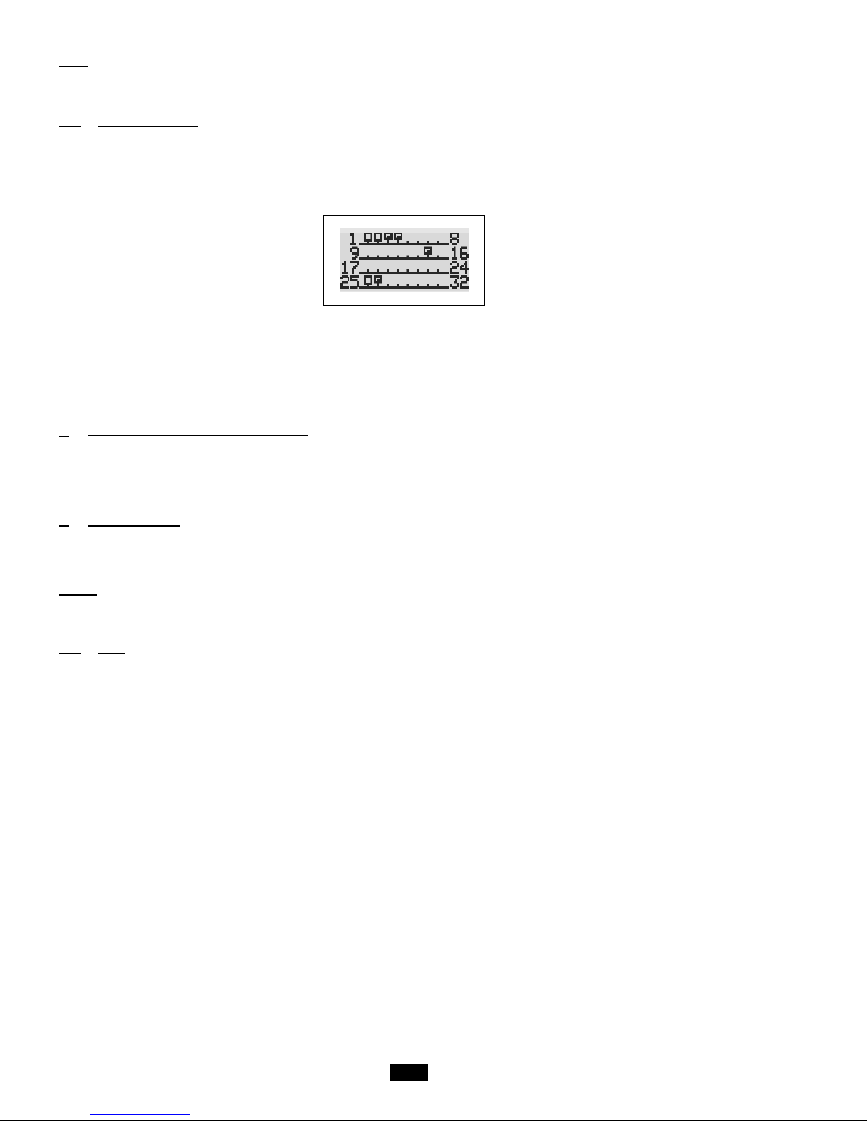
44
3.3.3 Checking the pLAN address
The pLAN address is displayed in the top left of the main screen, the pLAN NETWORK pL1 screen in the "Communication" menu
and the Program pr1 screen of the "Version s" men u.
3.4 State of the pLAN
When the system starts up, the pLAN network may encounter a number of problems (card fault and terminal start-up) caused by
incorrect connections or a wrong address. The state of the pLAN network can be displayed in real time on a special mask in order
to identify which devices (controller or terminal) are correctly connected and addressed.
To display this special page, simultaneously press and on any other terminal on the network for at least 10 seconds. After
the first 5 seconds, a page is displayed; after 5 more seconds, the next page appears:
NetSTAT Term : 17
Press Enter to quit
Once on the screen, network addresses 1 to 32 are displayed. The small rectangles represent the terminals and the large
rectangles , the controllers. If symbols appear then disappear, the pLAN may be unstable or, more likely, two components share
the same address. The number after Term indicates the address of the terminal used. The example shows that the network is
made up of 3 controllers with the addresses 1, 2, 25 and 4 terminals with the addresses 3, 4, 15 and 26. Once the page has been
verified, turn off the power, check the connections and addresses, then turn the power back on.
4 Replacing the lithium battery
The lithium battery must be replaced by the customer when the notification alarm appears, approximately 10 years after the unit is
commissioned on s ite.
Once the replacement has been carried out, do not forget to reset the battery check (mask tp1)
5 Supervision
The controller may be connected to a local or remote supervision PC or to most types of CMS (Modbus, Lonworks, KNX). For the
listed functions to be used, optional cards (Rs485, KNX, LON) or gateways (devices able to interpret various communication
protocols) must be installed
NOTE:
If using a communication bus, the routing and processing of the available data are outside CIAT's scope of supply. They must be
provided by the installer, and require the involvement of an integrator.
5.1 CMS
Modbus® RTU: insert the RS485 expansion board (CIAT code: 7119749) and connect it as described in the manual. Val i da t i ng t he
protocol on the user terminal (screen g1):
- Protocol MODBUS RTU
- Speed ---- bds (Set in accordance with the CMS speed)
- Address 001 (Different to 0)
Modbus® TCP: insert the pCo Web card (CIAT code: 7119753) and connect it as described in the manual. Valida ting t he protocol
on the user terminal (screen g1):
- Protocol MODBUS TCP
- Speed 19200 bds (Obligatory)
- Address 001 (Different to 0)
LonWorks®: insert the expansion board (CIAT code: 7323026 (type FTT-10A)) and connect it as instructed in the manual.
Validating the protocol on the user terminal (screen g1):
- Protocol LON
- Speed 4800 bds (Obligatory)
- Address 001 (Obligatory)
KNX®: insert the expansion board (CIAT code: 7265072) and connect it as instructed in the manual. Validating the KNX protocol
on the user terminal (screen g1):
- Protocol KNX
- Speed 9600 bds (Obligatory)
- Address 001 (Obligatory)
Page 45
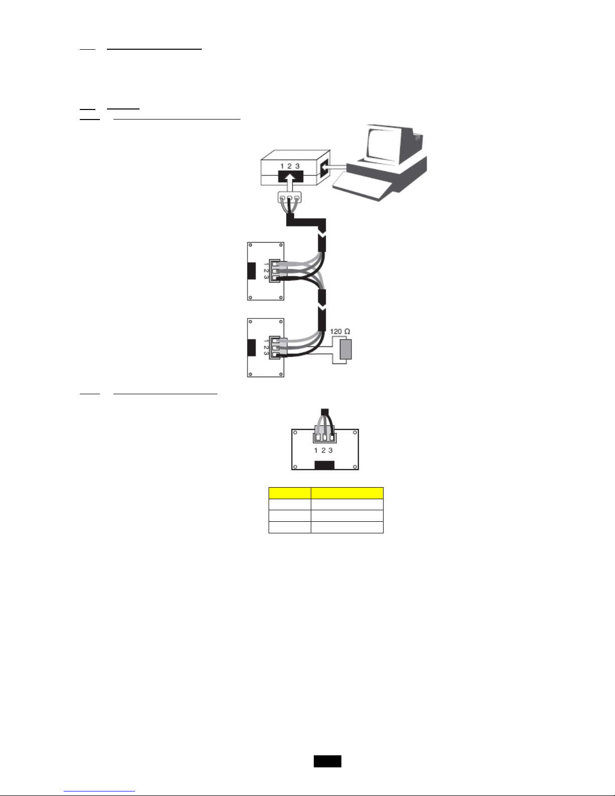
45
5.2 The datapoint database
The unit comes with a communication database that includes the m ost important datapoints for the program, from the values of the
sensors to the parameters displayed in the masks. The database contains three types of datapoint: digital datapoints, integer
datapoints and analogue datapoints. The tables below list the names of these datapoints, their addresses and types (read-only (R)
or read/write (R/W)).
5.3 Modbus
5.3.1 Modbus RTU connection diagram
5.3.2 RS485 connection close-up
Pin
Description
1
GND
2
RX+/TX+
3
RX-/TX-
The components required for connection to the remote and/or local ModBus supervision system are as follows:
- An RS485 serial card (CIAT code: 7119749) connected to each controller.
- A standard RS485/USB converter for connection to a PC (not supplied by CIAT). The converter can be connected to any
network RS485 card.
- An electri cal networ k using an AWG20/22 shielded cable (not supplied by CIAT) comprising a twis ted pair and shielding
with a max length of 1000 m. This network must never run parall el to power cables at a distance of less than 50 cm.
These cables may cross, but perpendicularly. You are requested not to form a loop with the network cable or the earth
braid, and to properly separate the various cable families (control, power, earth and communication bus).
- A supervision program installed on a PC (not supplied by CIAT).
An 120Ω ¼W electrical resistor must be connected to the RS485 serial card in last position on the bus, as shown in the connection
diagram.
The format of the data frame, which cannot be modified, is as follows: 8 data bits, 2 stop bits and without parity on 2 words (2
bytes), high-order, low-order.
The data format (16 bits, signe d) is standard for Modbus except for analogue data which is in the format "Integer divided by 10"
Page 46
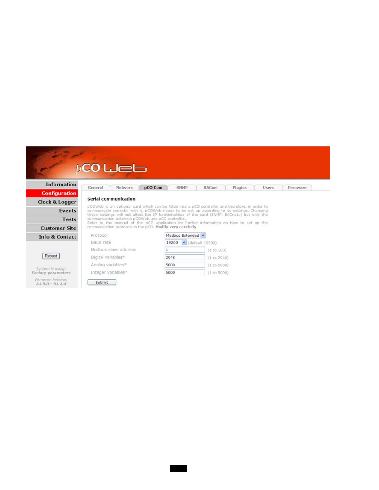
46
The codes for the Modbus functions used are:
- 1 or 2: Read n bits
- 3 or 4: Read multiple registers (16 bits)
- 5: Write one bit
- 6: Write one register
- 8: Read diagnostics counter s
- 11: Read event counter
- 15: Write n bits
- 16: Write multiple registers (16 bits)
NB: The JBus addresses are equal to the "Modbus address" - 1
5.3.3 Modbus TCP connection
The Modbus TCP protocol connection requires a communication card to be connected and configured as shown below. The speed
(baud rate) must be identical in the communication menu.
Page 47
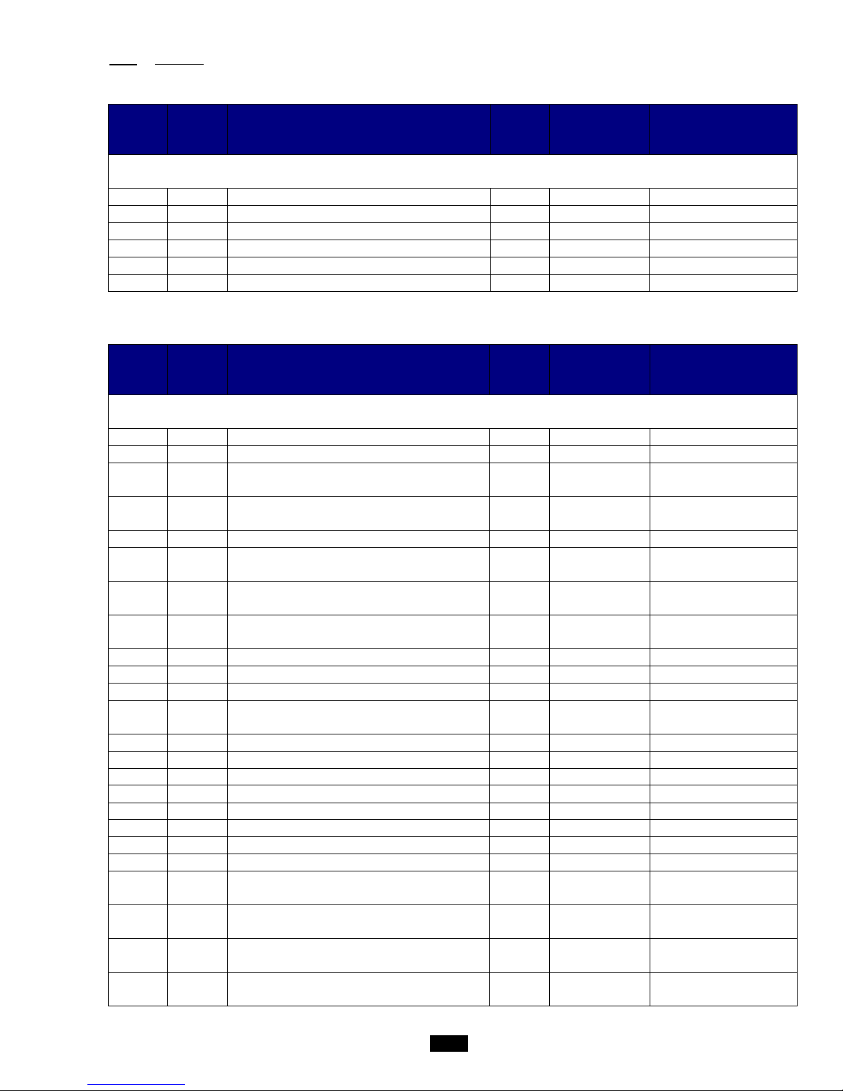
47
5.3.4 Variables
5.3.4.1 Commands
Register
hex. no.
Register
decimal
no.
Description Format Type Adjustable values
Registers accessible in read-only mode (function 1) and write mode (function 5)
0x118 280 Remote on/off command Boolean Read-only/Write 0: Off/1: On
0x119 281 Fault acknowledgement Boolean Read-only/Write 0: No/1: Acknowledgement
0x11A 282 Electric heater load shedding Boolean Read-only/Write 0: Free / 1: Load shedding
0x11B 283 Unit actuation at eco/comfort temperature Boolean Read-only/Write 0: Comfort / 1: Eco
0x11C 284 Unit actuation at eco/comfort flow rate Boolean Read-only/Write 0: Co m fo r t / 1 : Eco
0x11D
285
Unit actuation at eco/comfort pressure
Boolean Read-only/Write 0: Co m fo r t / 1 : Eco
5.3.4.2 Setpoints
Register
hex. no.
Register
decimal
no.
Description Format Type Adjustable values
Dampers accessible in read-only mode (functions 3 or 4) and write mode (functions 6 for char or 16)
0x0190 400 Supply air fan Comfort flow rate setpoint value Integer Read-only/Write m3/h /10
0x0191 401 Return air fan Comfort flow rate setpoint value Integer Read-only/Write m3/h /10
0x0192 402 Supply air fan Eco flow rate setpoint value Integer Read-only/Write m3/h /10
0x0193 403 Return air f an Eco flow rate setpoint value Integer Read-only/Write m3/h /10
0x0195 405 Supply air duct Comfort pressure setpoint value Integer Read-only/Write Pa
0x0196 406 S uppl y ai r duct Eco pressure setpoint value Integer Read-only/Write Pa
0x019A 410 Comfort heating regulated temperature setpoint value Integer Read-only/Write °C x10
0x019B 411 Eco heating regulated temperature setpoint value Integer Read-only/Write °C x10
0x019C 412 Supply air temperature maximum limit value Integer Read-only/Write °C x10
0x019D 413 Supply air temperature minimum limit value Integer Read-only/Write °C x10
0x1A1 417 Air quality control setpoint Integer Read-only/Write ppm
0x1A2 418
Supply air fan maximum flow rate value for air quality
regulation
Integer Read-only/Write m3/h /10
0x1A6 422 Cooling Comfort regulated temperature setpoint Integer Read-only/Write °C x10
0x1A7 423 Cooling Eco regulated temperature setpoint Integer Read-only/Write °C x10
0x1A8 424 Heating Comfort regulated temperature setpoint Integer Read-only/Write °C x10
0x1A9 425 Heating Eco regulated temperature setpoi nt Integer Read-only/Write °C x10
0x1AC 428 Cooling Comfort supply air temperature setpoint Integer Read-only/Write °C x10
0x1AD 429 Cooling Eco supply air temperature setpoint Integer Read-only/Write °C x10
0x1AE 430 Heating Comfort supply air temperature setpoint Integer Read-only/Write °C x10
0x1AF 431 Heating Eco supply air temperature setpoint Integer Read-only/Write °C x10
0x1B4 436
Frost protection setpoint value when the unit is in
Standby
Integer Read-only/Write °C x10
0x1B9 441 Temperature control setpoint in "Night cooling" mode Integer Read-only/Write °C x10
0x1BA 442 Duct pressure control setpoint in "Night cooling" mode Integer Read-only/Write Pa
0x1BB 443
Supply air fan flow rate control setpoint in "Night
cooling" mode
Integer Read-only/Write m3/h /10
Page 48
48
0x1BC 444
Return air fan flow rate control setpoint in "Night
cooling" mode
Integer Read-only/Write m3/h /10
0x1BD 445 Stage 1 and off setpoint value for the electric heater Integer Read-only/Write %
0x1BE 446 Stage 1 on setpoint value for the electric heater Integer Read-only/Write %
0x1BF 447 Stage 2 off setpoint value for the electric heater Integer Read-only/Write %
0x1C0 448 Stage 2 on setpoint value for the electric heater Integer Read-only/Write %
0x1C4 452
Free Cooling authorisation limit setpoint value in
relation to the fresh air temperature
Integer Read-only/Write °C x10
0x1C5 453
Value of the minimum % of fresh air during Free
cooling management
Integer Read-only/Write %
0x1D0 464 High threshold for supply air filter CF1 fouled fault Integer Read-only/Write Pa
0x1D1 465 High threshold for supply air filter CF1 clogged fault Integer Read-only/Write Pa
0x1D5 469 High threshold for return air filter CF1 fouled fault Integer Read-only/Write Pa
0x1D6 470 High threshold for return air filter CF1 clogged fault Integer Read-only/Write Pa
0x1DB 475 Stage off setpoint value for the DX coil Integer Read-only/Write %
0x1DC 476 St age on setpoint value for the DX coil Integer Read-only/Write %
0x1E5 485
Changeover limit setpoint value in Heating mode and
water return temperature
Integer Read-only/Write °C x10
0x1E6 486
Changeover limit setpoint value in Cooling mode and
water return temperature
Integer Read-only/Write °C x10
0x1E7 487
Value for the water return temperature control
proportional band
Integer Read-only/Write °C x10
0x1EB 491 Duct pressure sensor fault low threshold Integer Read-only/Write Pa
0x1EC 492 Duct press ure sensor fault hi gh threshold Integer Read-only/Write Pa
Page 49
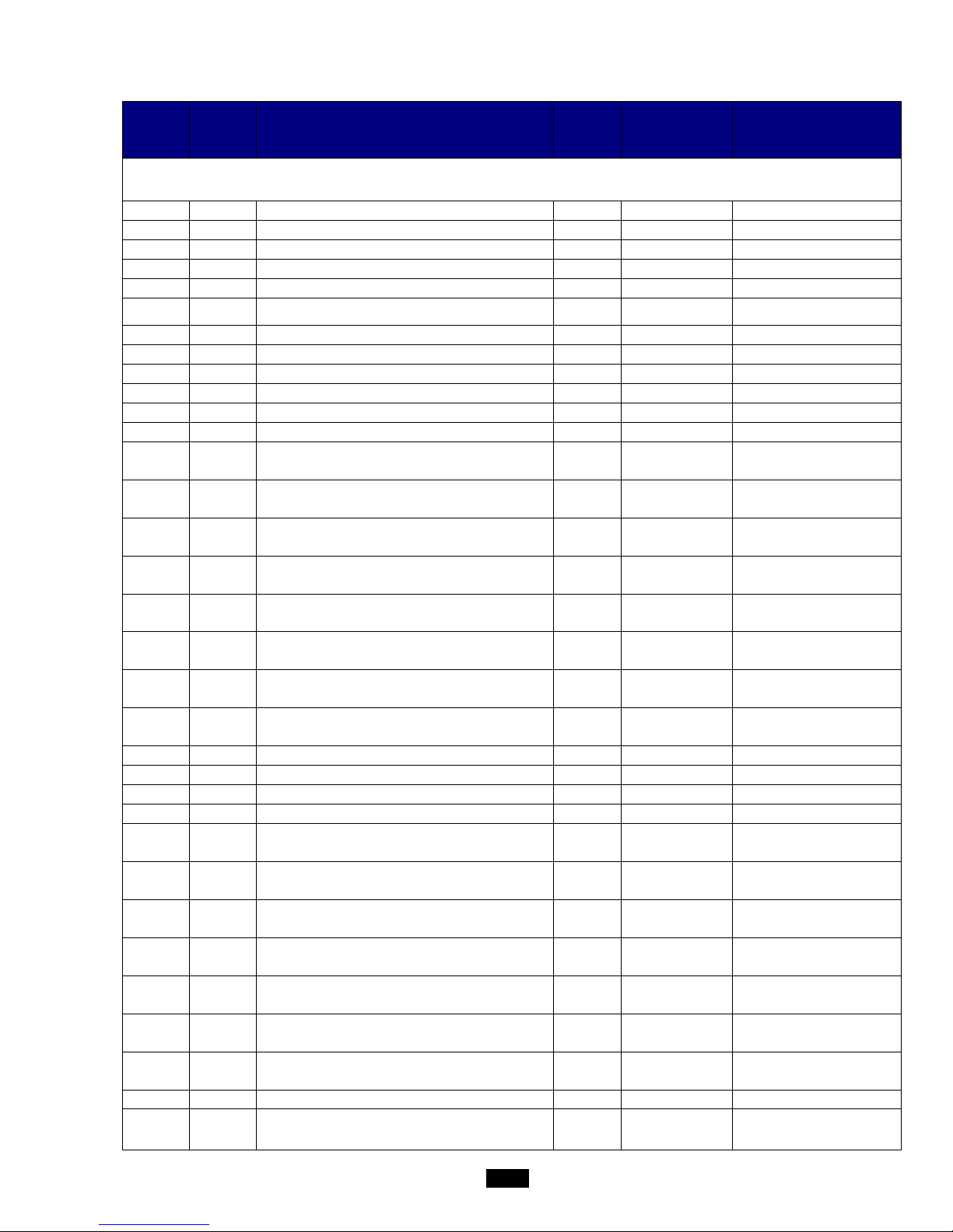
49
5.3.4.3 Reading parameters
Register
hex. no.
Register
decimal
no.
Description Format Type Values displayed
Dampers accessible in read-only mode (functions 3 or 4)
0x44C 1100 Supply air temperature Integer Read-only Value x10
0x44D 1101 Ret urn ai r temperature Integer Read-only Value x10
0x44E 1102 Ambient temperature Integer Read-only Value x10
0x44F 1103 Fresh air temperature Integer Read-only Value x10
0x450 1104 Water network temperature Integer Read-only Value x10
0x453 1107 Filter CF2 pressure switch control input state Boolean Read-only
0 = No fault
1 = Fault
0x454 1108 Supply air fan flow rate Integer Read-only Value /10
0x455 1109 Return air fan flow rate Integer Read-only Value /10
0x456 1110 Duct pressure Integer Read-only
0x458 1112 Supply air filt er CF1 fouling Integer Read-only
0x459 1113 Return air filter CF1 fouling Integer Read-only
0x45C
1116
Air quality in ppm of CO2
Integer
Read-only
0x45E 1118 Supply air fan monitoring input state Boolean Read-only
0 = Contact open
1 = Contact closed
0x45F 1119 Return air fan monitoring input state Boolean Read-only
0 = Contact open
1 = Contact closed
0x460 1120 Fire input state Boolean Read-only
0 = Fault
1 = No fault
0x467 1127 Humidifier monitoring Boolean Read-only
0 = Fault
1 = No fault
0x468 1128
Electric heater load shedding command or Selection of
heating coil
Boolean Read-only
0 = Not Shed / EC
1 = Load shedding / EL
0x469 1129 Remote control input state Boolean Read-only
0 = Off
1 = On
0x46C 1132 Electric heater safety thermostat input state Boolean Read-only
0 = Fault
1 = No fault
0x46E 1134 Antifreeze thermostat input state Boolean Read-only
0 = No fault
1 = Fault
0x474 1140 Supply air variable drive command signal Integer Read-only
0x475 1141 Return air variable drive command signal Integer Read-only
0x476 1142 Opening percentage for coil 1 Integer Read-only
0x477
1143
Opening percentage for coil 2
Integer
Read-only
0x47D 1149 "Danger" fault summary relay Boolean Read-only
0 = No fault
1 = Fault
0x47E 1150 "Maintenance" fault summary relay Boolean Read-only
0 = No fault
1 = Fault
0x483 1155 Damper servomotor state Boolean Read-only
0 = Damper closed
1 = Damper open
0x484 1156 Stage 1 state for the electric heater Boolean Read-only
0 = Off
1 = On
0x485 1157 Stage 2 state for the electric heater Boolean Read-only
0 = Off
1 = On
0x488 1160 Stage state for the DX coil Boolean Read-only
0 = Off
1 = On
0x48E 1166 Humidifier operation authorisation output state Boolean Read-only
0 = Off
1 = On
0x491 1169 Mixing output value Integer Read-only
0x492 1170 Mixing command direction of action Integer Read-only
0:Non
1:Opening
2:Closed
Page 50

50
0x49E 1182 Calculated supply air setpoint value Integer Read-only Value x10
0x4A5 1189 Supply air fan runtime counters Integer Read-only in hours
0x4A6 1190 Option to reset the counters Boolean Read/Write 1 = Reset
0x4AB 1195 Return air fan runtime counters Integer Read-only in hours
0x4AC 1196 Option to reset the counters Boolean Read/Write 1 = Reset
0x4B2 1202 Stage 1 electric heater runtime counters Integer Read-only in hours
0x4B3 1203 Option to reset the counters Boolean Read/Write 1 = Reset
0x4B4 1204 Stage 2 electric heater runtime counters Integer Read-only in hours
0x4B5 1205 Option to reset the counters Boolean Read/Write 1 = Reset
0x4B8 1208 Humidifier runtime counters Integer Read-only in hours
0x4B9 1209 Option to reset the counters Boolean Read/Write 1 = Reset
0x4BA 1210 DX module runtime counters Integer Read-only in hours
0x4BB 1211 Option to reset the counters Boolean Read/Write 1 = Reset
0x4BC 1212 Heat recovery unit bypass runtime counters Integer Read-only in hours
0x4BD 1213 Option to reset the counters Boolean Read/Write 1 = Reset
0x4DA 1242 Software version number Integer Read-only
0x4DB 1243 Suffix number Integer Read-only
0x4DC 1244 Day Integer Read-only
0x4DD 1245 Month Integer Read-only
0x4DE 1246 Year Integer Read-only
0x4DF 1247 Bios version Integer Read-only
0x4E0 1248 Bios suffix Integer Read-only
0x4E1 1249 Boot version Integer Read-only
0x4E2 1250 Boot suffix Integer Read-only
0x4E3 1251 SO number part 1 Integer Read-only
0x4E4 1252 SO number part 2 Integer Read-only
0x4E5 1253 Box number part 1 Integer Read-only
0x4E6 1254 Box number part 2 Integer Read-only
0x500
1280
Unit state
Integer
Read-only
0: Off 1:
On 2: On
after cutout 3:
Standby 4:
Stop by fault 5: Stop
by CMS 6: Post
ventilation 7:
Manual mode
0x501
1281
Heating requirement supplied by unit
Integer
Read-only
0x502 1282 Cooling requirement supplied by unit Integer Read-only
Page 51
51
5.3.4.4 Alarms
Register
hex. no.
Register
decimal
no.
Description Format Type
Dampers accessible in read-only mode (functions 3 or 4)
0x514 1300 Level 0 fault (critical fault) Boolean 0 or 1
0x515 1301 Level 10 fault (Non-c r itical fault) Boolean 0 or 1
0x516 1302 Supply air motor alarm Boolean 0 or 1
0x518 1304 Filter 1 dirty alarm Boolean 0 or 1
0x51C 1308 Fire alarm Boolean 0 or 1
0x51D 1309 Antifreeze alarm Boolean 0 or 1
0x51E 1310 Electric heater overheating alarm Boolean 0 or 1
0x51F 1311 Supply air temperature too high alarm Boolean 0 or 1
0x520 1312 Supply air temperature too low alarm Boolean 0 or 1
0x521 1313 Room or return ai r temperature too high alarm Boolean 0 or 1
0x522 1314 Room or ret urn ai r temperat ure too low alarm Boolean 0 or 1
0x523 1315 Return air motor alarm Boolean 0 or 1
0x524 1316 Filter 1 blocked alarm Boolean 0 or 1
0x526 1318 Fi l ter 2 dirty alarm Boolean 0 or 1
0x527 1319 F i l t er 2 blocked al arm Boolean 0 or 1
0x528 1320 Fi l ter 3 dirty alarm Boolean 0 or 1
0x52B 1323 Heat recovery unit alarm in frosting phase Boolean 0 or 1
0x52C 1324 Timer battery replacement alarm Boolean 0 or 1
0x52E 1326 Duct pressure alarm Boolean 0 or 1
0x530 1328 Humidifier alarm Boolean 0 or 1
0x531 1329 Ambient or return air humidity too high alarm Boolean 0 or 1
0x532 1330 Ambient or return air humidity too low alarm Boolean 0 or 1
0x541 1345 Heat recovery unit fouled alarm Boolean 0 or 1
Page 52
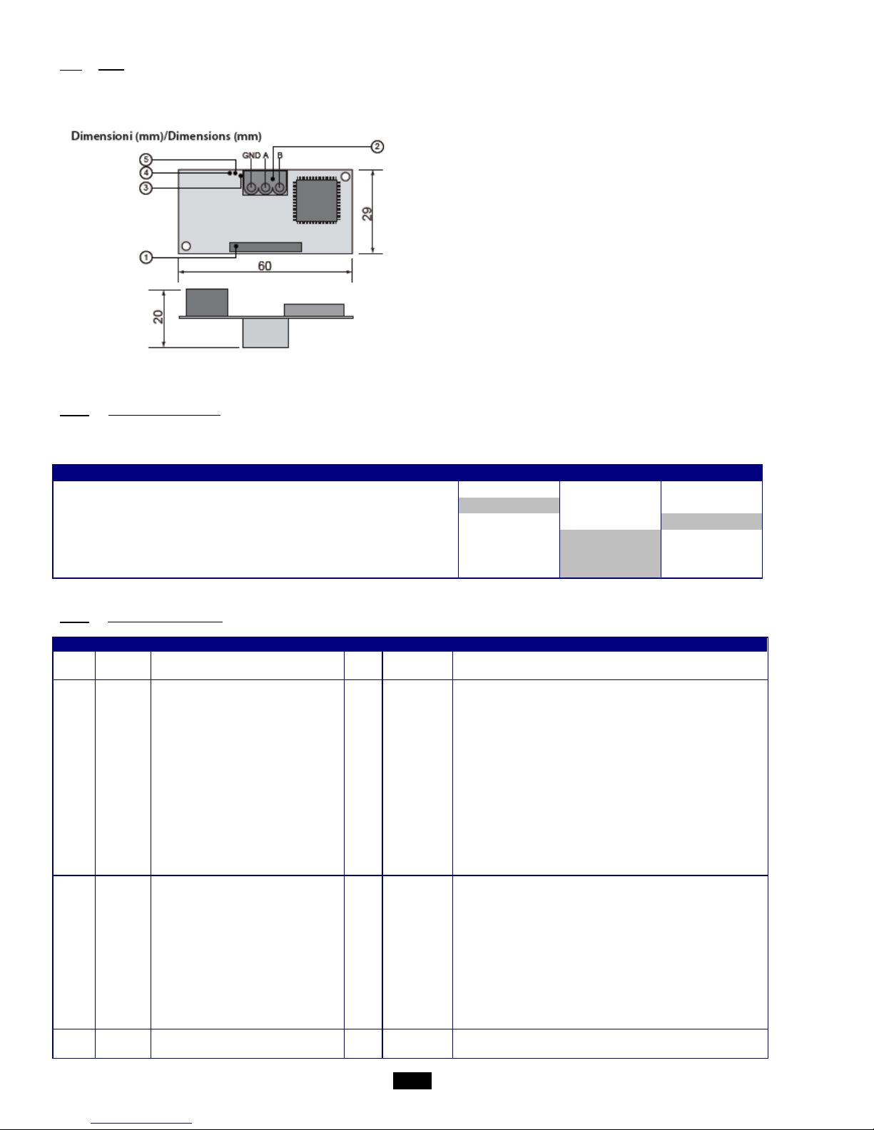
52
5.4 LON
The communication card is supplied preloaded. The information data is retrieved via the CMS using a shunt on the Pin Service on
the front panel of the expansion board.
1. Connector for the controller
2. Disconnectable terminal for connection of the
LonWorks® network (GND, A, B)
3. Pin service
4. Green service LED: state of the node, lit during the pin
service, flashing when the board receives a command
from the network, if permanently lit = board faulty
5. Red fault LED: signals a board installation problem
(connection, communication s peed 4800 bd s)
On request, the "Air_Technologies_110905.XIF" file is available.
5.4.1 LON scope of supply
Recap of on-site LON tasks by CIAT/Installer/Integrator for commissioning:
Task
CIAT
Integrator
Installer
Commissioning service
Supply of .XIF integration file
Installation of units equipped with LON controller
Addressing and configuration of LON network
Definition of master/slave zones
Definition of setpoints and time programs
5.4.2 The digital datapoints
Type
Index
NV name
SNVT
Direction
Description
DGT 1 nvi_GTC_OnOff
95
input
Unit On/Off command via CMS
DGT 1 nvo_GTC_OnOff
95
output
Unit On/Off command return via CMS
DGT
--
nvo_entree_dig_1
83
output
State of digital inputs
bit 0
Not used
bit 1
Not used
bit 2
Supply air fan control state
bit 3
Antifreeze thermostat control state
bit 4
Not used
bit 5
Fire sensor state
bit 6
Electric heater thermostat sensor input
bit 7
Remote control state
bit 8
Return air fan control state
bit 9
Not used
bit 10
Not used
bit 11
Not used
bit 12
Not used
DGT
--
nvo_sortie_dig_1
83
output
State of digital outputs
bit 0
Danger fault output
bit 1
Maintenance fault output
bit 2
Not used
bit 3
Not used
bit 4
Damper control
bit 5
Electric heater stage 1 control
bit 6
Electric heater stage 2 control
bit 7
Stage control for the DX coil
bit 8
Humidifier authorisation control
bit 9
Plate heat exchanger bypass servomotor control
DGT
--
nvo_alarm_01_16
83
output
Alarm 1 value:
bit 0
Motor alarm
Page 53

53
bit 1
Return air motor alarm
bit 2
Not used
bit 3
Supply air filter 1 dirty alarm
bit 4
Supply air filter 1 blocked alarm
bit 5
Not used
bit 6
Return air filter 2 dirty alarm
bit 7
Return air filter 2 blocked alarm
bit 8
Additional filter 3 dirty alarm
bit 9
Not used
bit 10
Not used
bit 11
Not used
bit 12
Not used
bit 13
Fire alarm
bit 14
Antifreeze alarm
bit 15
Electric heater safety thermostat alarm
DGT
--
nvo_alarm_17_32
83
output
Alarm 2 value:
bit 0
Low supply air temperature alarm
bit 1
High supply air temperature alarm
bit 2
Low ambient or return air temperature alarm
bit 3
High ambient or return air temperature alarm
bit 4
Humidifier alarm
bit 5
Heat recovery unit fouled alarm
bit 6
pLAN alarm
bit 7
Clock lithium battery alarm
bit 8
Duct pressure alarm
bit 9
Not used
bit 10
Not used
bit 11
Not used
bit 12
Not used
Page 54

54
5.4.3 The analogue datapoints
Type
Index
NV name
SNVT
Direction
Description
ANL 1 nvo_custom_1
113
output
Supply air filter CF1 fouling level
ANL 2 nvo_custom_2
113
output
Supply air duct pressure
ANL 3 nvo_custom_3
113
output
Return air filter CF1 fouling level
ANL 5 nvo_custom_5
113
output
Heat exchanger fouling
ANL 8 nvo_custom_8
161
output
Supply air fan flow rate
ANL 9 nvo_custom_9
161
output
Return air fan flow rate
ANL
16
nvo_custom_16
105
output
Room or return air temperature
ANL
17
nvo_custom_17
105
output
Supply air temperature
ANL
18
nvo_custom_18
105
output
Fresh air temperature
ANL
19
nvo_custom_19
105
output
Network water temperature
ANL
25
nvo_sortie_ana_1
9
output
Coil No.1 capacity
ANL
26
nvo_sortie_ana_2
9
output
Coil No.2 capacity
ANL
27
nvo_sortie_ana_3
9
output
Supply air variable drive
ANL
28
nvo_sortie_ana_4
9
output
Return air variable drive
ANL
37
nvo_etat_unite
9
output
Unit operating state:
Value 0
off
Value 1
opening of damper
Value 2
on
Value 3
switched on after a power failure
Value 4
standby
Value 5
switched off by a fault
Value 6
switched off by CMS
Value 7
post ventilation
ANL 44 nvi_T_regul 105 input
Comfort regulated temperature setpoint in "Precision"
mode (return or ambient)
ANL 44 nvo_T_regul 105 output
Comfort regulated temperature setpoint return in mode
"Precision" mode (return or ambient)
ANL
48
nvi_D_regul
161
input
Comfort supply air fan flow rate setpoint
ANL
48
nvo_D_regul
161
output
Comfort supply air fan flow rate setpoint return
ANL
49
nvi_P_regul
113
input
Comfort duct pressure setpoint
ANL
49
nvo_P_regul
113
output
Comfort duct pressure setpoint return
Page 55
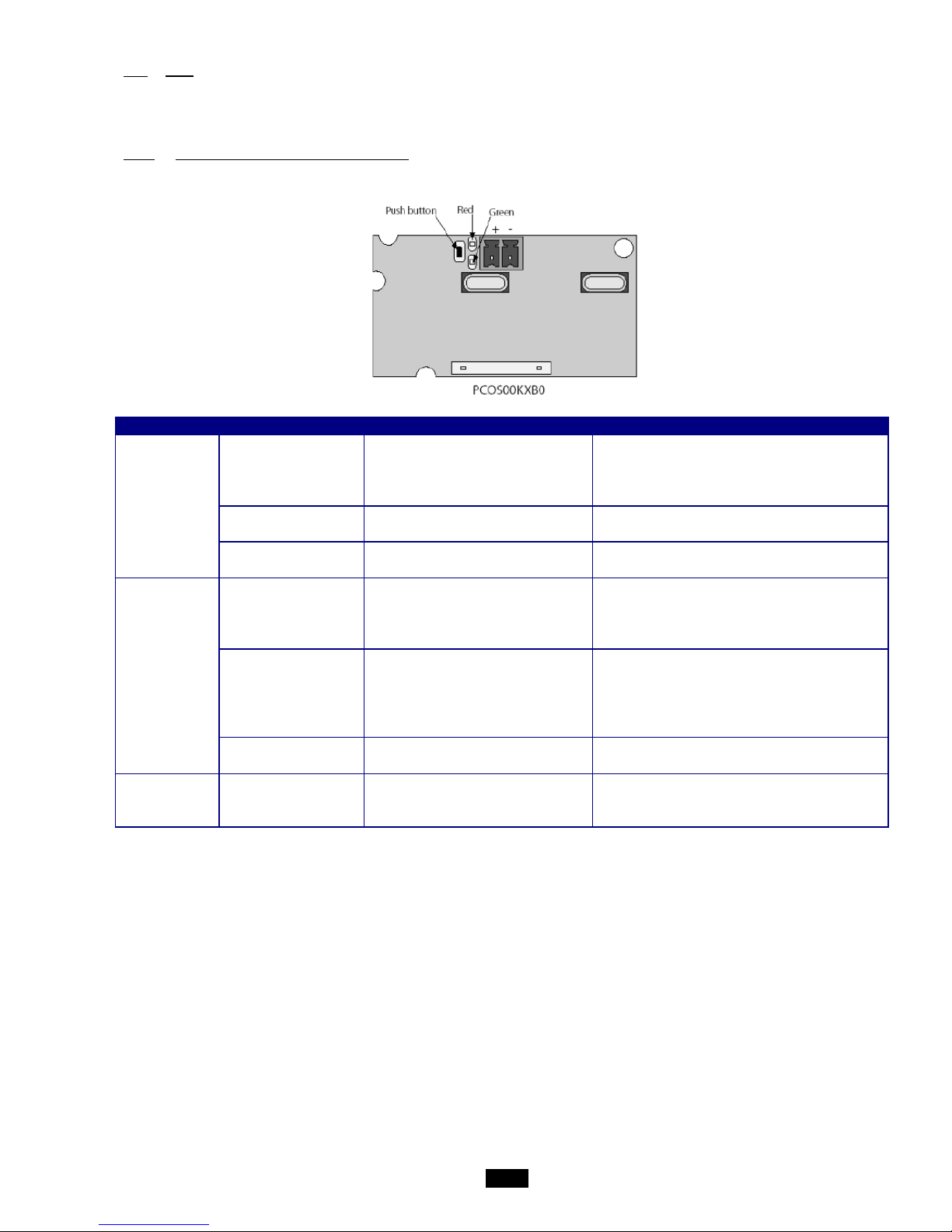
55
5.5 KNX
The bus used is a TP1, with a transmission speed of 9600 Bds.
This bus requires a special external power supply (supplied as an option; CIAT code: 7222279)
5.5.1 Description of KNX communication card
LED
Meaning
Cause / solution
Red
Constantly lit
No communication between KNX
card and the controller
Check the configuration:
- controller address incorrect
- transmission speed incorrect
- wrong protocol
Flashing
Communication error between KNX
card and the controller
The card has been configured with a version or
address not recognised by the controller BIOS
Off
Communication with the pCO3 is
established
Green
Constantly lit
The button has been pressed to
allocate the address, and the card is
awaiting the corresponding
procedure from ETS3
Rapidly flashing -
the XML file has not been
downloaded
-
a rapid flash indicates receipt of
the address after the button has
been pressed
Proceed with configuration
Slow flashing
Configuration in progress: the XML
file is being downloaded by ETS3
Green + Red
Both constantly lit No power supply on KNX bus
Check: KNX bus power supply, electrical
connections and polarity of connections on the
connector + and - terminals
Page 56

56
5.5.2 Variables
The KSet software for configuring the group addresses is provided alongside the Carel_plugin_21.PR4 file for the ETS3 software
tool (not provided) (Carel_plugin_30.PR5 file for the ETS4 software (not provided)) and the CTA-V30.XML file for the database
below:
Description
Datapoint
Name
Datapoint
TypeName
Datapoint
TypeCode
IN/OUT
Index
TYPE
Supply air filter CF1
fouling level
Filtre1
DPT_Value_Temp
9.001
OUT
1112
REG
Supply air duct
pressure
PressionGaine
DPT_Value_Temp
9.001
OUT
1110
REG
Supply air
temperature
TemperatureSoufflage
DPT_Value_Temp
9.001
OUT
1100
REG
Return air temperature
TemperatureReprise
DPT_Value_Temp
9.001
OUT
1111
REG
Return air filter CF1
fouling level
Filtre2
DPT_Value_Temp
9.001
OUT
1113
REG
Fresh air or outdoor
temperature
TemperatureNeuf
DPT_Value_Temp
9.001
OUT
1103
REG
Ambient temperature
TemperatureAmbiante
DPT_Value_Temp
9.001
OUT
1102
REG
Supply air fan flow
rate
DebitVentilSoufflage
DPT_Value_Temp
9.001
OUT
1108
REG
Return air fan flow
rate
DebitVentilReprise
DPT_Value_Temp
9.001
OUT
1109
REG
CO2 air quality
QualiteAir
DPT_Value_Temp
9.001
OUT
1116
REG
Network water
temperature
TemperatureReseau
DPT_Value_Temp
9.001
OUT
1104
REG
Water coil valve No. 1
Batterie1
DPT_Value_Temp
9.001
OUT
1142
REG
Supply air fan control
VitesseVentilSoufflage
DPT_Value_Temp
9.001
OUT
1140
REG
Return air fan control
VitesseVentilReprise
DPT_Value_Temp
9.001
OUT
1141
REG
Water coil valve No. 2
Batterie2
DPT_Value_Temp
9.001
OUT
1143
REG
Mixing damper
Melange
DPT_Value_Temp
9.001
OUT
1169
REG
Supply air fan Comfort
flow rate control
setpoint
WVentSConfort
DPT_Value_Temp
9.001
IN
400
REG
Supply air fan Comfort
flow rate control
setpoint return
WVentSConfort
DPT_Value_Temp
9.001
OUT
400
REG
Return air fan Comfort
flow rate control
setpoint
WVentRConfort
DPT_Value_Temp
9.001
IN
401
REG
Return air fan Comfort
flow rate control
setpoint return
WVentRConfort
DPT_Value_Temp
9.001
OUT
401
REG
Supply air fan Eco
flow control setpoint
WVentSEco
DPT_Value_Temp
9.001
IN
402
REG
Supply air fan Eco
flow rate control
setpoint return
WVentSEco
DPT_Value_Temp
9.001
OUT
402
REG
Return air fan Eco
flow control setpoint
WVentREco
DPT_Value_Temp
9.001
IN
403
REG
Return air fan Eco
flow rate control
setpoint return
WVentREco
DPT_Value_Temp
9.001
OUT
403
REG
Comfort pressure
control setpoint for
the Supply air duct
WPressionConfort
DPT_Value_Temp
9.001
IN
405
REG
Comfort pressure
control setpoint return
for the Supply air duct
WPressionConfort
DPT_Value_Temp
9.001
OUT
405
REG
Eco pressure control
setpoint for the
Supply air duct
WPressionEco
DPT_Value_Temp
9.001
IN
406
REG
Eco pressure control
setpoint return for the
Supply air duct
WPressionEco
DPT_Value_Temp
9.001
OUT
406
REG
Control setpoint for
the monitored
Comfort temperature
in "Precision" mode
WTempRegulConfort
DPT_Value_Temp
9.001
IN
410
REG
Control setpoint
return for the
monitor ed Comfort
temperature in
WTempRegulConfort
DPT_Value_Temp
9.001
OUT
410
REG
Page 57

57
"Precision" mode
Control setpoint for
the monitored Eco
temperature in
"Precision" mode
WTempRegulEco
DPT_Value_Temp
9.001
IN
411
REG
Control setpoint
return for the
monitor ed Eco
temperature in
"Precision" mode
WTempRegulEco
DPT_Value_Temp
9.001
OUT
411
REG
Upper limit for the
calculated Supply air
T° setpoint in
"Precision" mode
Limite MaxTSouffl
DPT_Value_Temp
9.001
IN
412
REG
Upper limit return for
the calculated Supply
air T° setpoint in
"Precision" mode
Limite MaxTSouffl
DPT_Value_Temp
9.001
OUT
412
REG
Low limit for the
calculated Supply air
T° setpoint in
"Precision" mode
Limite MinTSouffl
DPT_Value_Temp
9.001
IN
413
REG
Low limit return for
the calculated Supply
air T° setpoint in
"Precision" mode
Limite MinTSouffl
DPT_Value_Temp
9.001
OUT
413
REG
CO2 air quality
setpoint
WQualiteAir
DPT_Value_Temp
9.001
IN
417
REG
CO2 air quality
setpoint return
WQualiteAir
DPT_Value_Temp
9.001
OUT
417
REG
Maximum flow rate
value of supply air fan
for air quality control
WVentSMaxQualite
DPT_Value_Temp
9.001
IN
418
REG
Supply air fan
maximum flow rate
value return for air
quality control
WVentSMaxQualite
DPT_Value_Temp
9.001
OUT
418
REG
Control setpoint for
the monitored
Comfort Cooling
temperature in
"Energy optimisation"
mode
WTempRegulConfortFroid
DPT_Value_Temp
9.001
IN
422
REG
Control setpoint
return for the
monitor ed Comfort
Cooling temperature
in "Energy
optimisation" mode
WTempRegulConfortFroid
DPT_Value_Temp
9.001
OUT
422
REG
Control setpoint for
the monitored Eco
Cooling temperature
in "Energy
optimisation" mode
WTempRegulEcoFroid
DPT_Value_Temp
9.001
IN
423
REG
Control setpoint
return for the
monitor ed Eco
Cooling temperature
in "Energy
optimisation" mode
WTempRegulEcoFroid
DPT_Value_Temp
9.001
OUT
423
REG
Control setpoint for
the monitored
Comfort Heating
temperature in
"Energy optimisation"
mode
WTempRegulConfortChaud
DPT_Value_Temp
9.001
IN
424
REG
Control setpoint
return for the
monitor ed Comfort
Heating temperature
in "Energy
optimisation" mode
WTempRegulConfortChaud
DPT_Value_Temp
9.001
OUT
424
REG
Control setpoint for
the monitored Eco
Heating temperature
in "Energy
WTempRegulEcoChaud
DPT_Value_Temp
9.001
IN
425
REG
Page 58

58
optimisation" mode
Control setpoint
return for the
monitor ed Eco
Heating temperature
in "Energy
optimisation" mode
WTempRegulEcoChaud
DPT_Value_Temp
9.001
OUT
425
REG
Control setpoint for
the Comfort Cooling
supply air temperature
in "Energy
optimisation" mode
WTempSoufflConfortFroid
DPT_Value_Temp
9.001
IN
428
REG
Control setpoint
return for the Comfort
Cooling supply air
temperature in
"Energy optimisation"
mode
WTempSoufflConfortFroid
DPT_Value_Temp
9.001
OUT
428
REG
Control setpoint for
the Eco Cooling
supply air temperature
in "Energy
optimisation" mode
WTempSoufflEcoFroid
DPT_Value_Temp
9.001
IN
429
REG
Control setpoint
return for the Eco
Cooling supply air
temperature in
"Energy optimisation"
mode
WTempSoufflEcoFroid
DPT_Value_Temp
9.001
OUT
429
REG
Control setpoint for
the Comfort Heating
supply air temperature
in "Energy
optimisation" mode
WTempSoufflConfortChaud
DPT_Value_Temp
9.001
IN
430
REG
Control setpoint
return for the Comfort
Heating supply air
temperature in
"Energy optimisation"
mode
WTempSoufflConfortChaud
DPT_Value_Temp
9.001
OUT
430
REG
Control setpoint for
the Eco Heating
supply air temperature
in "Energy
optimisation" mode
WTempSoufflEcoChaud
DPT_Value_Temp
9.001
IN
431
REG
Control setpoint
return for the Eco
Heating supply air
temperature in
"Energy optimisation"
mode
WTempSoufflEcoChaud
DPT_Value_Temp
9.001
OUT
431
REG
Unit reactivation
setpoint in "Standby"
mode when there is an
ambient temperature
sensor
WTempHorsGel
DPT_Value_Temp
9.001
IN
436
REG
Unit reactivation
setpoint return in
"Standby" mode when
there is an ambient
temperature sensor
WTempHorsGel
DPT_Value_Temp
9.001
OUT
436
REG
Control setpoint in
"Night cooling" mode
WTempNocturne
DPT_Value_Temp
9.001
IN
441
REG
Control setpoint
return in "Night
cooling" mode
WTempNocturne
DPT_Value_Temp
9.001
OUT
441
REG
Unit operating state
0 = off
1 = on
2 = on after power
failure
3 = standby
4 = off by a fault
5 = off by CMS
6 = post ventilation
EtatUnite
DPT_Value_2_Ucount
7.001
OUT
1280
REG
Alarm 1 value:
Alarme1
DPT_Value_2_Ucount
7.001
OUT
27
REG
Page 59

59
Bit 0 = Supply air
motor alarm
Bit 1 = Return air
motor alarm
Bit 2 = Not used
Bit 3 = Supply air filter
CF1 dirty alarm
Bit 4 = Supply air filter
CF1 blocked alarm
Bit 5 = Not used
Bit 6 = Return air filter
CF1 dirty alarm
Bit 7 = Return air filter
CF1 blocked alarm
Bit 8 = Additional filter
CF2 dirty alarm
Bit 9 = Not used
Bit 10 = Not used
Bit 11 = Not used
Bit 12 = Not used
Bit 13 = Fire alarm
Bit 14 = Antifreeze
protection alarm
Bit 15 = Electric heater
safety thermostat
alarm
Alarm 2 value:
Bit 0 = Low supply air
temperature alarm
Bit 1 = High supply air
temperature alarm
Bit 2 = Low ambient or
return air temperature
alarm
Bit 3 = High ambient
or return air
temperature alarm
Bit 4 = Humidifier
alarm
Bit 5 = Heat recovery
unit fouled alarm
Bit 6 = pLAN alarm
Bit 7 = Timer lithium
battery alarm
Bit 8 = Duct pressure
alarm
Bit 9 = Not used
Bit 10 = Not used
Bit 11 = Not used
Bit 12 = Not used
Alarme2
DPT_Value_2_Ucount
7.001
OUT
28
REG
Heating requirement
supplied by unit
Chaud
DPT_Value_2_Ucount
7.001
OUT
1281
REG
Cooling requirement
supplied by unit
Froid
DPT_Value_2_Ucount
7.001
OUT
1282
REG
Unit On/Off command
via CMS
OnoffGTC
DPT_Switch
1.001
IN
280
COIL
Unit On/Off command
return via CMS
OnoffGTC
DPT_Switch
1.001
OUT
280
COIL
Reset of alarms not
present command
ResetAlarmes
DPT_Switch
1.001
IN
281
COIL
Reset of alarms not
present command
return
ResetAlarmes
DPT_Switch
1.001
OUT
281
COIL
Electric heater load
shedding
Delestage
DPT_Switch
1.001
IN
282
COIL
Electric heater load
shedding return
Delestage
DPT_Switch
1.001
OUT
282
COIL
Temperature-
dependent machine
actuation in Eco /
Comfort mode
ConfortEcoTemp
DPT_Switch
1.001
IN
283
COIL
Temperature-
dependent machine
actuation return in
Eco / Comfort mode
ConfortEcoTemp
DPT_Switch
1.001
OUT
283
COIL
Flow rate -dependent
ConfortEcoDebit
DPT_Switch
1.001
IN
284
COIL
Page 60

60
machine actuation in
Eco / Comfort mode
Flow rate -dependent
machine actuation
return in Eco /
Comfort mode
ConfortEcoDebit
DPT_Switch
1.001
OUT
284
COIL
Pressure-dependent
machine actuation in
Eco / Comfort mode
ConfortEcoPression
DPT_Switch
1.001
IN
285
COIL
Pressure-dependent
machine actuation
return in Eco /
Comfort mode
ConfortEcoPression
DPT_Switch
1.001
OUT
285
COIL
"Danger" fault
summary
DefautDanger
DPT_Switch
1.001
OUT
1149
COIL
"Maintenance" fault
summary
DefautMaintenance
DPT_Switch
1.001
OUT
1150
COIL
Damper control (frost
protection or
insulation)
Registre
DPT_Switch
1.001
OUT
1155
COIL
Electric heater stage 1
control
BattElec1
DPT_Switch
1.001
OUT
1156
COIL
Electric heater stage 2
control
BattElec2
DPT_Switch
1.001
OUT
1157
COIL
DX coil stage control
BattElec3
DPT_Switch
1.001
OUT
1160
COIL
Page 61

61
Page 62
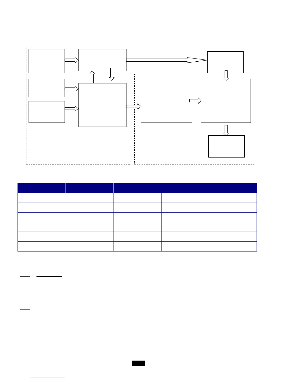
62
5.5.3 Configuration process
The diagram below illustrates the phases of the "configuration process" required for configuring the card correctly:
The types of KNX Datapoint available and the respective conversion methods are listed in the table below:
Type
Name
Standard ID Format KNX ran ge
Range available in
the controller
Boolean
(DPT_Switch)
1.001
1 bit
Off / On
Off / On
Unsigned 8 bit
(DPT_Value_1_Ucount)
5.010
Unsigned 8 bits
0 to 255
0 to 255
Signed 8 bit
(DPT_Value_1_Count)
6.010
Signed 8 bits
-128 to +127
-128 to +127
Unsigned 16 bits
(DPT_Value_2_Ucount)
7.001
Unsigned 16 bits
0 to 65535
0 to 32767
Signed 16 bits
(DPT_Value_2_Count)
8.001
Signed 16 bits
-32768 to +32767
-32768 to +32767
Floating 16 bits
(DPT_Value_Temp)
9.001
Floating 16 bits
-671088.64 to
+670760.96
-3276.8 to +3276.7
It is important to remember that the same group address cannot be as si gned to more than one Dat apoi nt.
5.5.4 CAREL plugin
As is the case for other m anufacturers' devices, the ETS3 data archives must be loaded with a specific description of the device.
CAREL distributes a plugin in the form of a "project database", which assigns the addresses and downloads the table created by
K-Set, i.e., the XML file.
5.5.5 Installing the plugin
The plugin is installed as follows:
. Find the file "Carel_plugin_21.pr4" (the updated version of the plugin is available from ksa.carel.com)
. Import "Carel_plugin_21.pr4" using Files → Import as s hown below:
XML file
No group
addresses
kSET:
Enter the group
addresses
ETS3 project
.pr4 file
with the
CAREL Plugin
ETS3
Create the links
between the various
datapoints, i.e.,
allocate the group
addresses
XML file
complete
ETS3
Assign the addresses
to all the modules, and
configure products
other than CAREL
XML file
Download XML file to
the CAREL modules
(table with group
addresses)
END
of installation
OFF-line: linkage of variables
ON-line:
Download the configuration
Physical connection to
network required
Page 63
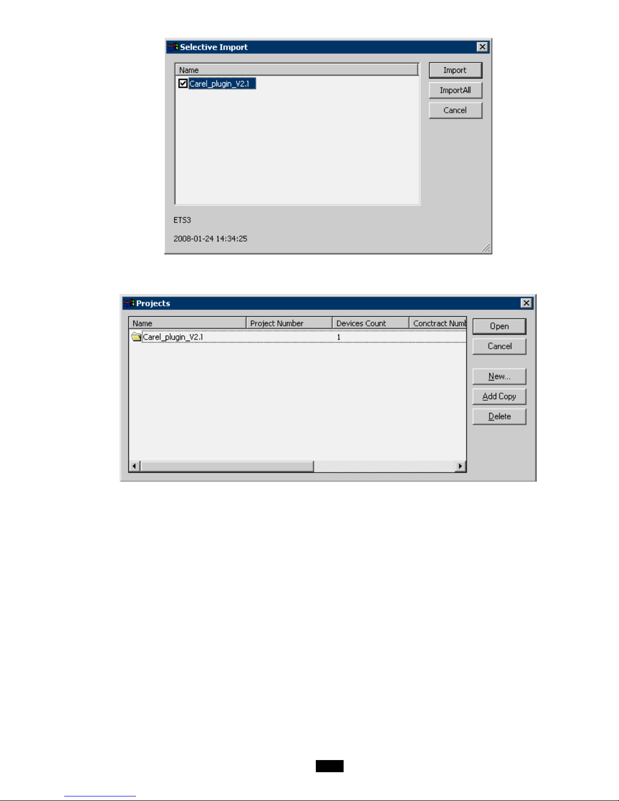
63
. Select Import all
. Using Files → "Open/Manage projects…", open the project named Carel_plugin_V2.1 (or above):
. Open the project using Open, select the device "CAREL Plugin", right-click on the mouse and select Copy:
Page 64
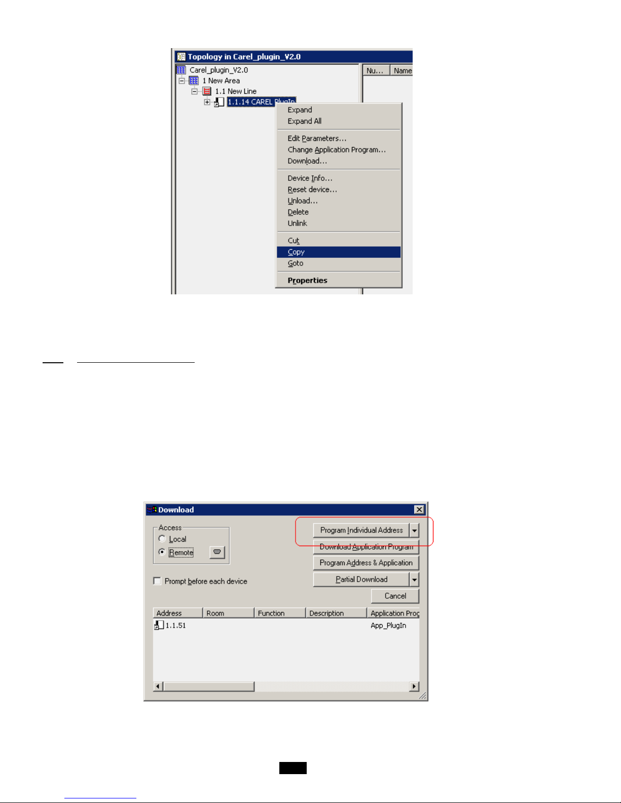
64
. Open or create the final project for the system and right-click on the mouse to paste the CAREL plugin, once or more
according to the number of CAREL devices to be integrated. The address of each device is automatically incremented. If
necessary, you can manually change the address of a device in Properties.
5.5.6 Assigning the physical address
The physical address of the CAREL KNX card is assigned using the standard procedure.
You must be sure that:
. the Bus wire network is drawn out and connected
. the Bus is ener gised
. the CAREL card is connec ted to the KNX network
. the controller is powered on
Use the mouse to select the controller to be configured, right-cli ck to open the "Download" menu, Fig.7.d and Fig.7.e.
Select "Program Individual Address" to activate the configuration proc edure and press the button on the card. The green LED on
the card goes out to indic ate when the operation is complete. If the card address has already been configured, the message "The
address is already used by another device" is displayed.
Page 65
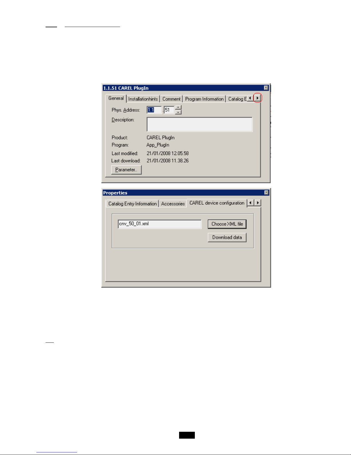
65
5.5.7 Downloading the XML file
You must be sure that:
. the Bus wire network is drawn out and connected
. the Bus is energised
. the CAREL card is connec ted to the KNX network
. the controller is powered on
Use the mouse to select the controller to be configured, right-click to open the "Properties" menu; scroll down the list using the
arrows at the top right until the label "CAREL device configuration" is displayed.
Use "Choose XML file" to open the XML configuration file required.
Click on "Download data" and wait for the "Success" message to be displayed. During this phase indicated by the "Performing
operation" message and the LED on the card flashing green, no other operation may be performed. The download time may vary
according to the size of the XML file and the network traffic; for a maximum size file, this time may be 2 minutes.
In extreme cases, i.e. high traffic and large XML files, the bus may be disconnected and ETS3 will signal an error. In this case,
simply repeat the downl oad.
NB: This procedure is specific for the CAREL card, and is the sole configuration operation permitted by the ETS3 program, in
addition to allocating the address.
Page 66
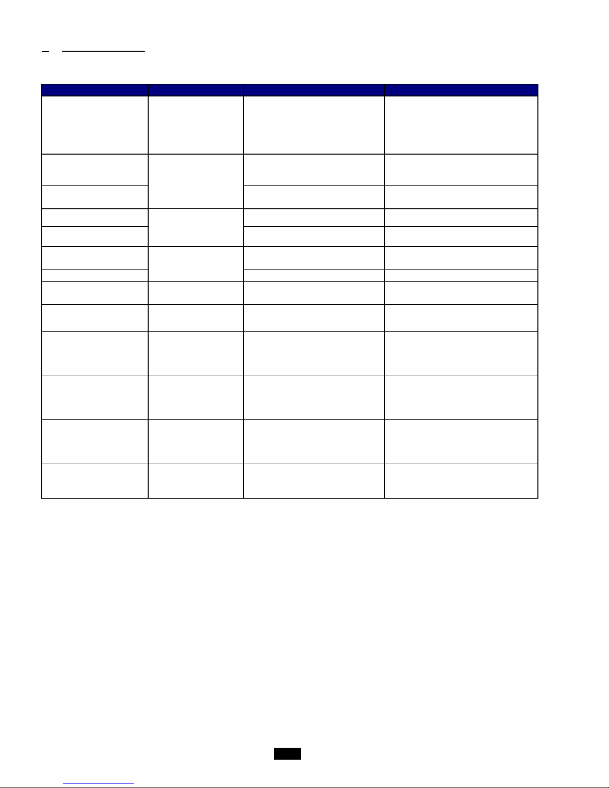
66
6 Table of alarms
* All possible options are covered by this table
Alarm
Sources
Causes
Solutions
Room or return air
temperature too high
Return air B1 or
ambient air th-Tune
temperature sensor
- Malfunction
- Sensor disconnected
- Room overheated
- Replace sensor
- Reconnect sensor
- Revise room loads
Ambient or return air
temperature too low
- Malfunction
- Sensor short-circuit
- Replace sensor
- Check sensor
Supply air temperature too
high
Supply air temperature
sensor
B2
- Malfunction
- Sensor disconnected
- Replace sensor
- Reconnect sensor
Supply air temperature too
low
- Malfunction
- Sensor short-circuit
- Replace sensor
- Check sensor
Supply air filter CF1
clogged
Supply air flow rate
pressure sensor
0-1000 Pa
B5
- Filter too dirty
- Replace filter
Supply air filter CF1 dirty
- Filter fouled
- Clean or replace filter
Return air filter CF1
clogged
Return air flow rate
pressure sensor
0-1000 Pa
B10
- Filter too dirty
- Replace filter
Return air filter CF1 dirty
- Filter fouled
- Clean or replace filter
Filter 3 dirty
Filter CF2 fouling level
pressure switch ID3
- Filter fouled
- Clean or replace filter
Humidifier
Cylinder
Water
ID9
- Cylinder dirty
- Water insufficiently conductive
- Change cylinder
- Add a handful of salt
Supply air motor
Supply air fan
monitoring
ID1
- Rotor blocked
- Phase check
- Voltage too low
- Thermal protection
- Short-circuit
- See causes
- Check wiring
- Monitor supply voltage
- Monitor starting current
- See causes
Antifreeze protection
Antifreeze thermostat
ID4
- Thermostat faulty
- See causes
Electric heater overheat
Electric heater safety
thermostat
ID6
- Thermostat faulty
- See causes
Return air motor
Return air fan
monitoring
ID2
- Rotor blocked
- Phase check
- Voltage too low
- Thermal protection
- Short-circuit
- See causes
- Check wiring
- Monitor supply voltage
- Monitor starting current
- See causes
Heat recovery unit fouled
Heat recovery unit
fouling level pressure
switch
ID10
- Fouling level greater than the setpoint
- Clean the heat exchanger
Page 67
67
Appendix: Component table – Control code (Main flow)
FV
F2V
FCV
F2CV
FEV
FTV
F2EV
F2TV
FCFV
FCMV
FCXV
F2CFV
F2CMV
F2CXV
FEFV
FTFV
Filter
CF2
Without
With
Without
With
Without
Without
With
With
Without
Without
Without
With
With
With
Without
With
Coil 1
Without
Without
Heating
Heating
Elec
Triac
Elec
Triac
Heating
Heating
Heating
Heating
Heating
Heating
Elec
Triac
Coil 2
Without
Without
Without
Without
Without
Without
Without
Without
Cooling
Mixed
DX
Cooling
Mixed
DX
Cooling
Cool
FEMV
FTMV
F2EFV
F2TFV
F2EMV
F2TMV
FFCV
FMCV
FXCV
F2FCV
F2MCV
F2XCV
FFEV
FFTV
FMEV
FMT
Filter
CF2
Without
Without
With
With
With
With
Without
Without
Without
With
With
With
Without
Without
Without
With
Coil 1
Elec
Triac
Elec
Triac
Elec
Triac
Cooling
Mixed
DX
Cooling
Mixed
DX
Cooling
Cooling
Mixed
Mixe
Coil 2
Mixed
Mixed
Cooling
Cooling
Mixed
Mixed
Heating
Heating
Heating
Heating
Heating
Heating
Elec
Triac
Elec
Triac
FXEV
FXTV
F2FEV
F2FTV
F2MEV
F2MTV
F2XEV
F2XTV
FFV
FMV
FXV
F2FV
F2MV
F2XV
Filter
CF2
Without
Without
With
With
With
With
With
With
Without
Without
Without
With
With
With
Coil 1
DX
DX
Cooling
Cooling
Mixed
Mixed
DX
DX
Cooling
Mixed
DX
Cooling
Mixed
DX
Coil 2
Elec
Triac
Elec
Triac
Elec
Triac
Elec
Triac
Without
Without
Without
Without
Without
Without
* DX -> Direct expansion
Page 68

68
Page 69

69
This document is not legally bindin g.
CIAT Service
Tel.: 08 11 65 98 98 - Fax: 08 26 10 13 63
This document is not legally binding.
As part of our continuous drive to improve our products, CIAT reserves the
right
to make any technical modifications without prior notice.
Registered address
Avenue Jean Falconnier B.P. 14
01350 Culoz – France
Tel.: 04 79 42 42 42
Fax: 04 79 42 42 10
[email protected] - www.ciat.com
Compagnie Industrielle
d’Applications Thermiques
S.A. with a capital of €26,728,480
R.C.S. Bourg-en-Bresse B 545.620.114
 Loading...