

Page 1

N 08.132 B
11 - 2008
Installation
Fonctionnement
Mise en service
Maintenance
Installation
Operation
Commissioning
Maintenance
Montage-
Betriebs-und
Wartungs-
Anweisung
AEROCONNECT
Page 2

Contents
.
.
.
.
.
.
.
.
.
.
.
.
.
.
.
.
.
.
.
.
.
.
.
.
.
.
.
.
.
.
.
.
.
.
.
.
.
.
.
.
.
.
.
.
.
.
.
.
.
.
.
.
.
.
.
Sections Page
General......................................................................................................................
Board functions..........................................................................................
Limits of use ...............................................................................................
Compatible equipment...............................................................................
Control console.........................................................................................................4
Description of control console .................................................................
Display ........................................................................................................
Menu tree structure....................................................................................
Menu list .......................................................................................
Structure of the menus................................................................
Navigation...................................................................................................
Board functions: description ..................................................................................
Control choices ..........................................................................................
On/Off control (stages) ................................................................
Speed control ...............................................................................
Mixed control................................................................................
Automatic operation control .....................................................................
Manual override..........................................................................................
Two setpoints .............................................................................................
Stage runtime balancing............................................................................
Spray ...........................................................................................................
Free cooling................................................................................................
Link with CIAT chiller.................................................................................
BMS link......................................................................................................
Options......................................................................................................................
Relay boards...............................................................................................
Remote control console ............................................................................
Electrical connections .............................................................................................
General........................................................................................................
Connection diagram...................................................................................
Board connections.....................................................................................
Dry cooler configuration..........................................................................................
Configurations............................................................................................
Commissioning and configuration ...........................................................
Information available while the unit is running .......................................
Factory-set parameters..............................................................................
Condenser configuration.........................................................................................
Configurations............................................................................................
Commissioning and configuration ...........................................................
Information available while the unit is running .......................................
Factory-set parameters..............................................................................
BMS communication protocol ................................................................................
Communication interface ..........................................................................
Transmission mode ...................................................................................
Remote signalling register ........................................................................
Remote alarm register ...............................................................................
Remote measurement register..................................................................
Fault memory..............................................................................................
Counters .....................................................................................................
Remote configuration register ..................................................................
Functions 1 and 2.......................................................................................
Remote alarm and operating status ...........................................
Remote control.............................................................................
Remote diagnostics.....................................................................
Event counter ...............................................................................
Glossary....................................................................................................................
3
3
3
3
4
5
5
5
5
6
7
7
7
7
8
8
8
8
8
8
9
9
9
10
10
10
10
10
11
13
16
16
16
18
19
20
20
20
21
23
24
24
24
24
25
25
26
26
27
29
29
29
29
29
30
EN - 2
Page 3
General
Board functions
Limits of use
Electrical
Compatible
equipment
Integrated in an electrical panel, this board performs the following functions:
• temperature or pressure control,
• operation parameter monitoring,
• communication with CIAT chillers,
• diagnostics and fault storage,
• communication with the remote control console, ancillary boards,
and customer BMS (bus).
Ambient air:
During operation: min./max. temperatures = -25°C/40°C
Stored: min./max. temperatures = -40°C/80°C
Single-phase fluid: min./max. adjustment temperature = 5/90°C (up to 150°C
optional)
Refrigerant: min./max. set pressure: 5/45 bar
Board supply voltage: 230 V
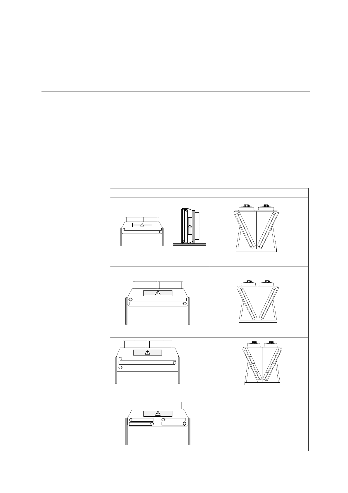
The AeroConnect board is used to control the dry coolers and air-cooled
condensers
Possible configurations and identification conventions:
Flatbed or V-type coils
Flatbed
+6%
-10%
V-type
Unit with one or two fan lines
Unit with one or two coils
Unit with one or two circuits
Line 1
Circuit 1 Circuit 2
Line 2
Coil 2
Coil 1
Coil 1
Line 1
Line 2
Coil 2
EN - 3
Page 4
Control console
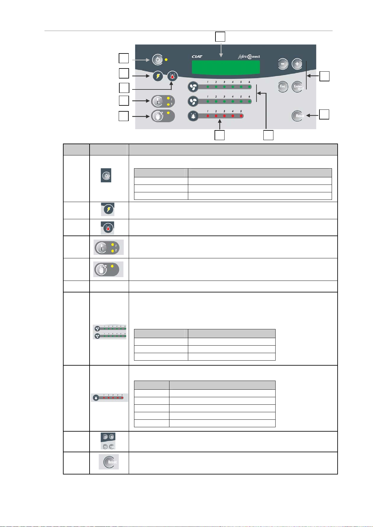
Description of
control console
(local and remote)
Letter Illustration Function
A
B
F
A
B
I
C
D
E
J
H G
Power button
LED Meaning
Off
On
Flashing
LED on = system energised.
Machine off
Machine on
Machine shut off by automatic control
C
D
E
F
G
H
I
LED flashing = fault
Press this button to select setpoint 1 or 2.
The corresponding LED lights up.
Press this button to activate or deactivate the fan manual override.
Flashing LED = manual override on.
Display screen.
Status of the fan stages:
• Top row = Fan line 1
• Bottom row = Fan line 2
LED Meaning
Off
On
Flashing
Measurement faults
LED No. Meaning
1
2
3
4
5
Menu navigation buttons: see the Navigation section.
Circuit 1 coil 1
Circuit 2 coil 1
Circuit 1 coil 2
Circuit 2 coil 2
Outdoor temperature
Stage off
Stage on
Stage fault
J
Reset button for certain faults.
Does not work with the remote control console.
EN - 4
Page 5
Control console (continued)
Display
Menu tree
structure
Menu list
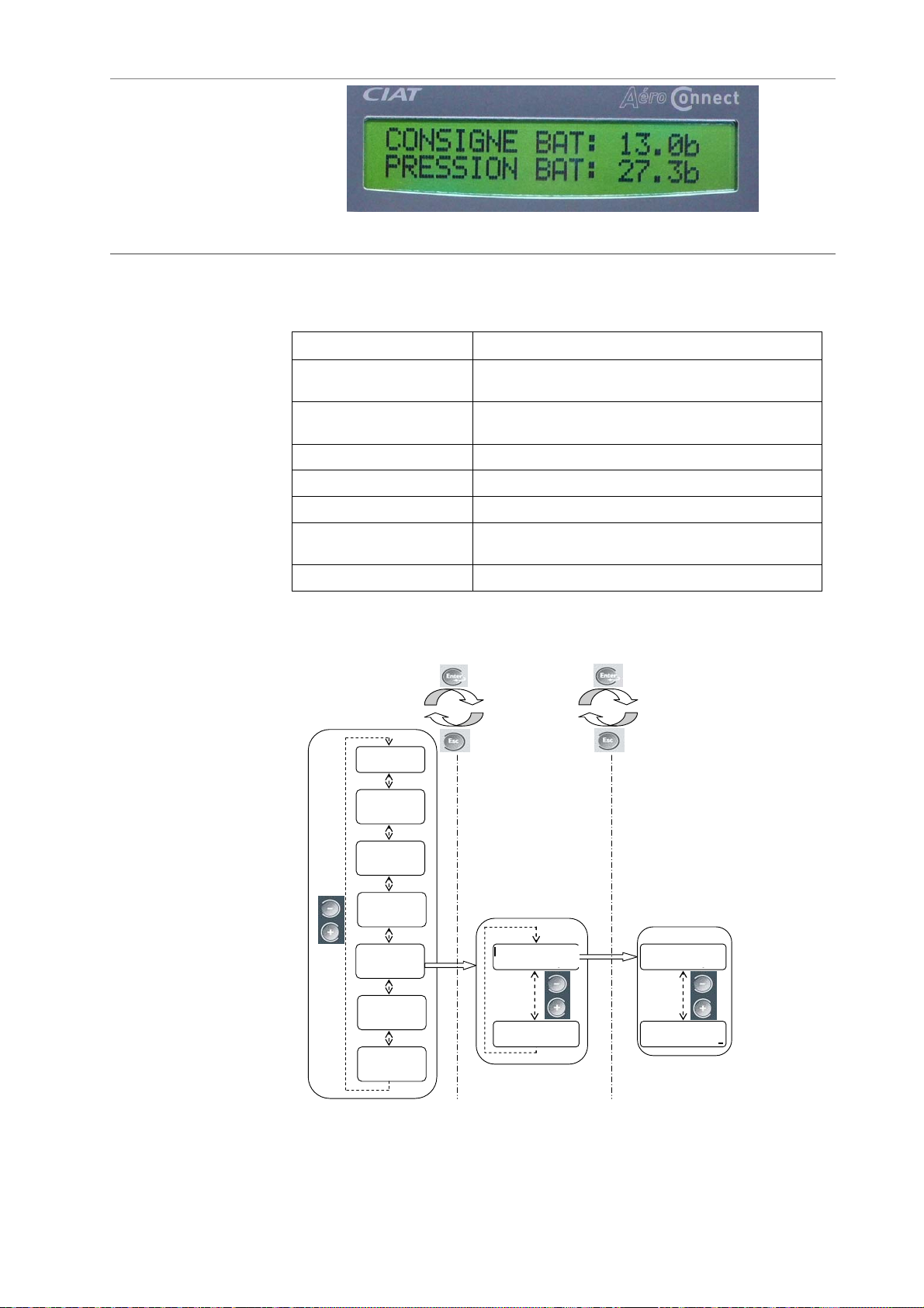
Two-line LCD – Displays system readings and controls.
There are seven main menus for controlling the system.
Each menu contains different parameters.
MENUS Description
1-Setpoints Change setpoints - Menu not displayed if the unit is
run with a CIAT chiller.
2-Machine status Default menu. Contains read-only information on the
operation of the machine.
3-Measured values Displays read-only temperature and pressure values.
4-Machine parameters Machine configuration parameters.
5-Settings parameters Parameters set for the control and various options.
6-Reading parameters Displays the status of the inputs, outputs, counters,
etc. (read-only).
7-Fault memory Shows the nine most recent faults (read-only).
Structure
of the menus
All information in the menus is displayed in a tree structure.
This tree structure is split into three levels, as shown by the diagram below.
MENUS
MENUS
PARAMETRES
PARAMETERS
MODIFICATION DES
CHANGING OF
VALEURS
VALUES
1-Consigne
1-Setpoint
2-Machine
2-Etat
status
machine
3-Measured
3-Valeurs
values
mesurees
4-Machine
4-Param
parameters
machine
5-Settings
-Param
parameters
de réglage
6-Read
6-Param de
parameters
Lecture
7-Fault
7-Memoire
memory
defauts
P100 Language
100 Langue
P203 ---------------
English
Français
-------
P100 Language
P100 Langue
P100 Langue
P100 Language
English
Français
----------
-------------
EN - 5
Page 6
Control console (continued)
Navigation
Navigating through
the menus
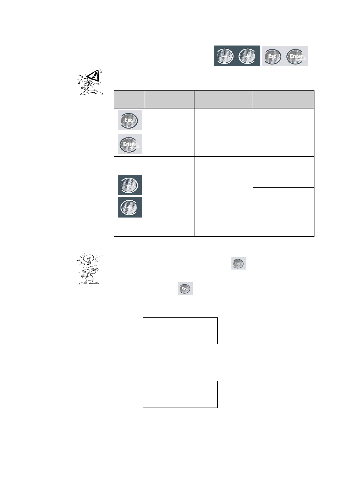
Four buttons are available for
navigating through the menus:
Each button is described in the table below:
Î Press these buttons firmly!
Button Level
Menus
Select menu Select parameter
Scroll
through the
menus
Level
Parameters
Back to
Menus level
Scroll
through the
parameters
Pressing and holding the ‘+’ or ‘-‘ buttons
will cause the display to scroll faster.
Level
Values
Back to
Parameters level
Confirm value and
go back to
parameters
Lower the
parameter value or
scroll through the
values
Raise the
parameter value or
scroll through the
values
When the machine is turned on, the "machine off – on/off" menu
[2-Machine status] screen appears. Press to go back to the menu
list.
If the control console is not used for one hour, the [2-Machine status]
menu reappears. Press to go back to the menu list.
Arrows on the right of the screen indicate that additional information is
available. To see this information, press the ‘+’ or ‘-‘ buttons.
Example
The active line in a menu is shown by a flashing box to the left of the menu
number.
Example
▮100 LANGUAGE
COIL PRESSURE ↑
20.7 B↓
ENGLISH
EN - 6
Page 7
Board functions: descriptions
Control
choices
On/Off control
Three types of control are possible. Refer to your order acknowledgement
to see which type you have selected:
• On/Off: Cascade control by activation of fan stages.
• Speed control: Fan speed control.
• Mixed: Speed control on stage 1, cascade control for the following
stages.
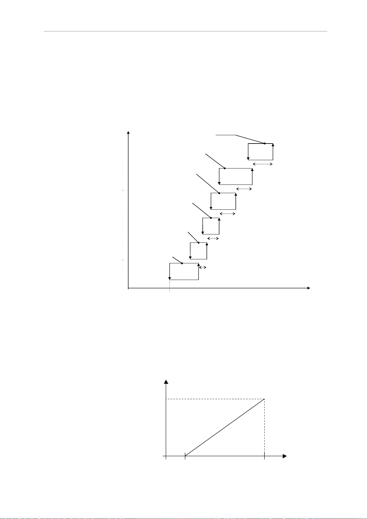
Used for cascade control of fan stages:
The diagram below illustrates this type of control:
A160 : Hystérésis étage 6
A 160: Stage 6 hysteresis
EXAMPLE FOR CIRCUIT 1
EXEMPLE POUR CIRCUIT 1
A 158 : Hystérésis étage 5
A 158: Stage 5 hysteresis
C
E
O
T
N
A
A156 : Hystérésis étage 4
A 156: Stage 4 hysteresis
T
G
R
E
O
L
D
A 154: Stage 3 hysteresis
E
A154 : Hystérésis étage 3
S
T
R
A
E
G
G
A152 : Hystérésis étage 2
A 152: Stage 2 hysteresis
E
U
L
A
T
A 150: Stage 1 hysteresis
A150 : Hystérésis étage 1
I
O
N
A155 : ∆ étage 4
A153 : ∆ étage 3
A151 : ∆ étage 2
stage 3
stage 2
A159 : ∆ étage 6
A157 : ∆ étage 5
stage 5
stage 4
Stage 6
Speed control
With a speed drive
(option)
A121 or A122 Setpoint
A121 ou A122 Consigne
Used to adjust the speed of all the fans.
The diagram below illustrates this type of control:
Voltage
Tension
EXAMPLE FOR COIL 1, CIRCUIT 1,
EXEMPLE BATTERIE 1 CIRCUIT 1
SETPOINT 1
CONSIGNE 1
10V
0V
(A150=hystérésis)
(A150=hysteresis)
A121 + A150
Measurement
Mesure
Measurement
EN - 7
Page 8
Board functions: descriptions (continued)
Control
choices
(continued)
Mixed control
With a speed drive
(option)
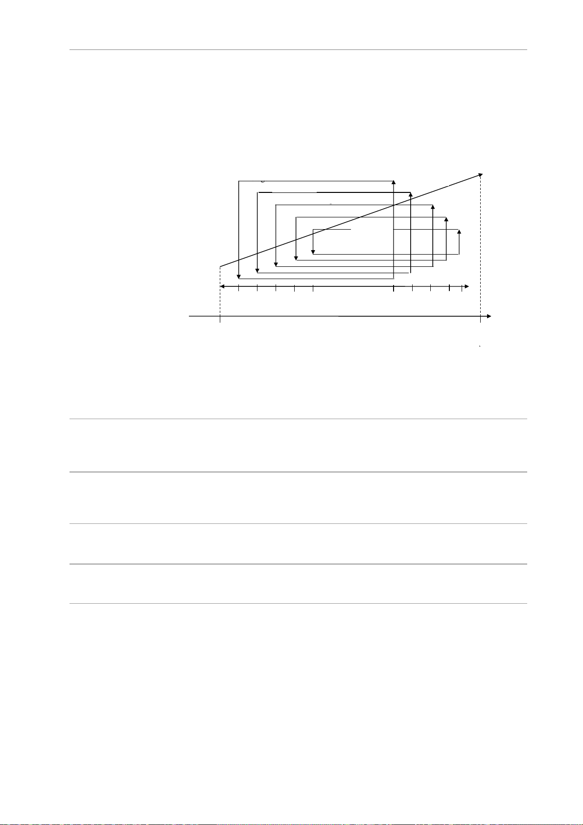
Used to adjust the speed on stage 1. Cascade control is used for the other
fan stages.
The diagram below illustrates this type of control:
2nd stage
2°étage
EXAMPLE FOR CIRCUIT 1
EXEMPLE POUR CIRCUIT 1
3°étage
3rd stage
4°étage
4th stage
5°étage
5th stage
6°étage
6th stage
1st stage
1°étage
5%
A121
Setpoint
Consigne
55% 65% 75% 85%
(A150=hysteresis)
(A150=hystérésis
95% 15% 25% 35% 45%
Measurement
A121 + A150
Automatic
machine operation
control
Manual
override
Two setpoints
Stage runtime
balancing
Spray
(units with spray
ducts)
Used to remotely authorise or prohibit the operation of the machine.
The machine is on when the contact is closed.
Used to turn on all the fans. The machine is in override mode when the
contact is closed.
Manual override can be activated and deactivated either directly on the unit or
remotely.
Used, for example, for summer/winter or day/night operation. Each circuit can
have up to two control setpoints. These setpoints can be switched via the dry
contact (On/Off), the console or over a BMS.
The running time of each fan stage is balanced by a time counter.
Used to increase the efficiency of the AeroConnect by spraying very fine
droplets of water into the ambient air to cool it through evaporation.
Two options:
- Optimised water consumption: the water spray does not start until all the
stages are on and the setpoint is exceeded.
- Optimised electricity consumption: the water spray does not come on until
the outdoor temperature reaches a preset value.
EN - 8
Page 9
Board functions: descriptions (continued)
p
Free cooling
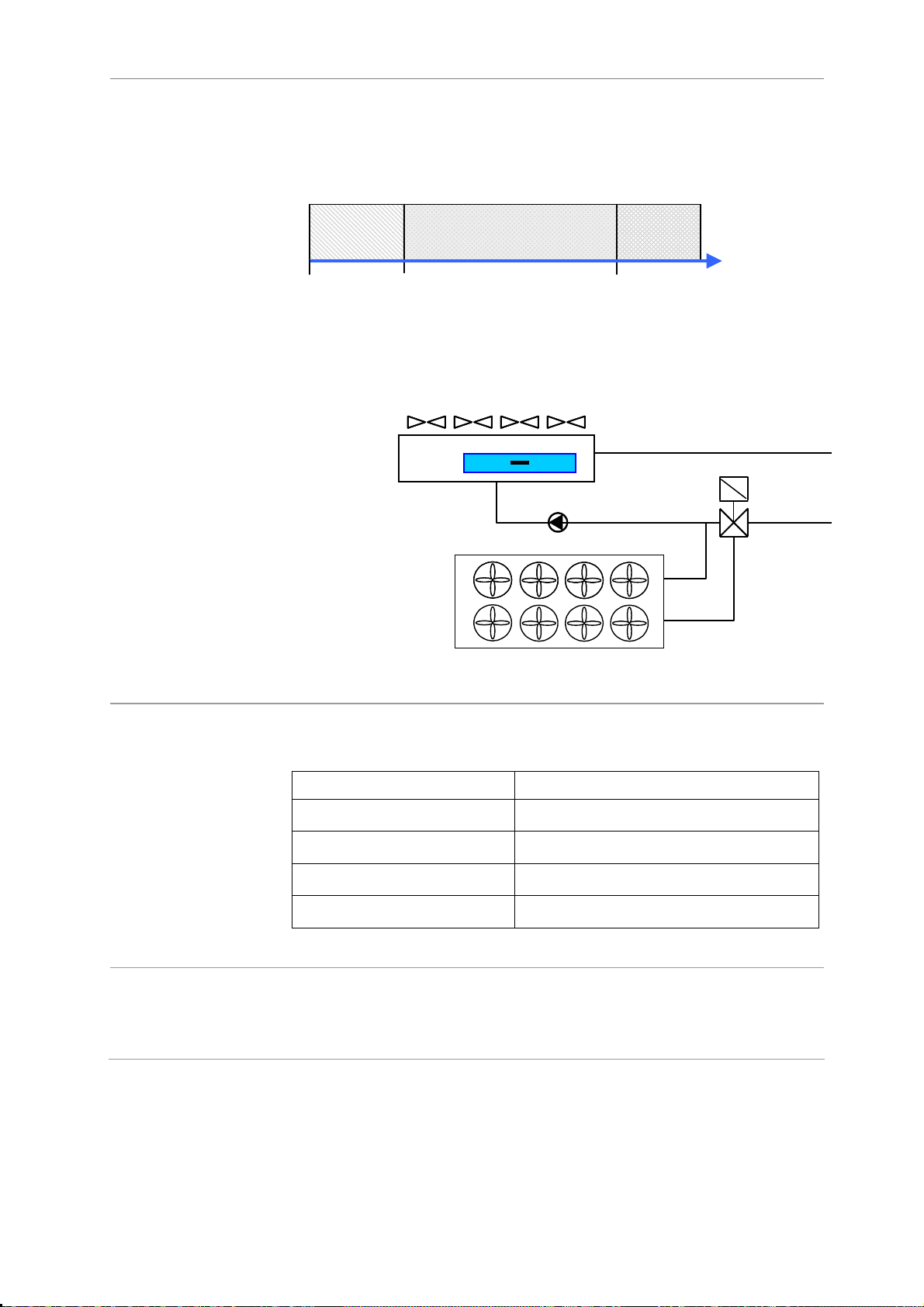
During free cooling, the dry cooler is run with a CIAT chiller. Both units are
controlled by the board.
The three-way valve can be controlled by the board provided the maximum
current is 3 A and the maximum voltage is 230 V. Refer to the chiller pump
curve to size the valve.
DC only
Chiller (CH)
Selection
temperature
P
CH only DRY COOLER + CHILLER
Process
return
tem
.
Text
Link with CIAT
chiller
BMS link
The following information is exchanged between the dry cooler (DC) or the
condenser (CO) and the chiller (CH):
CH > (DC / CO) (DC / CO) > CH
Dry cooler (DC)
• Chiller on/off • DC or CO on/off
• Setpoint (CO) • Free cooling
• Pressure value (CO) • Fan stage fault
With the exception of the language, control type (local, remote),
communication mode and bus number, all the parameters can be accessed
in read and write modes.
• Sensor fault
EN - 9
Page 10
Options
Relay boards
Main board
Additional board
Remote control
console
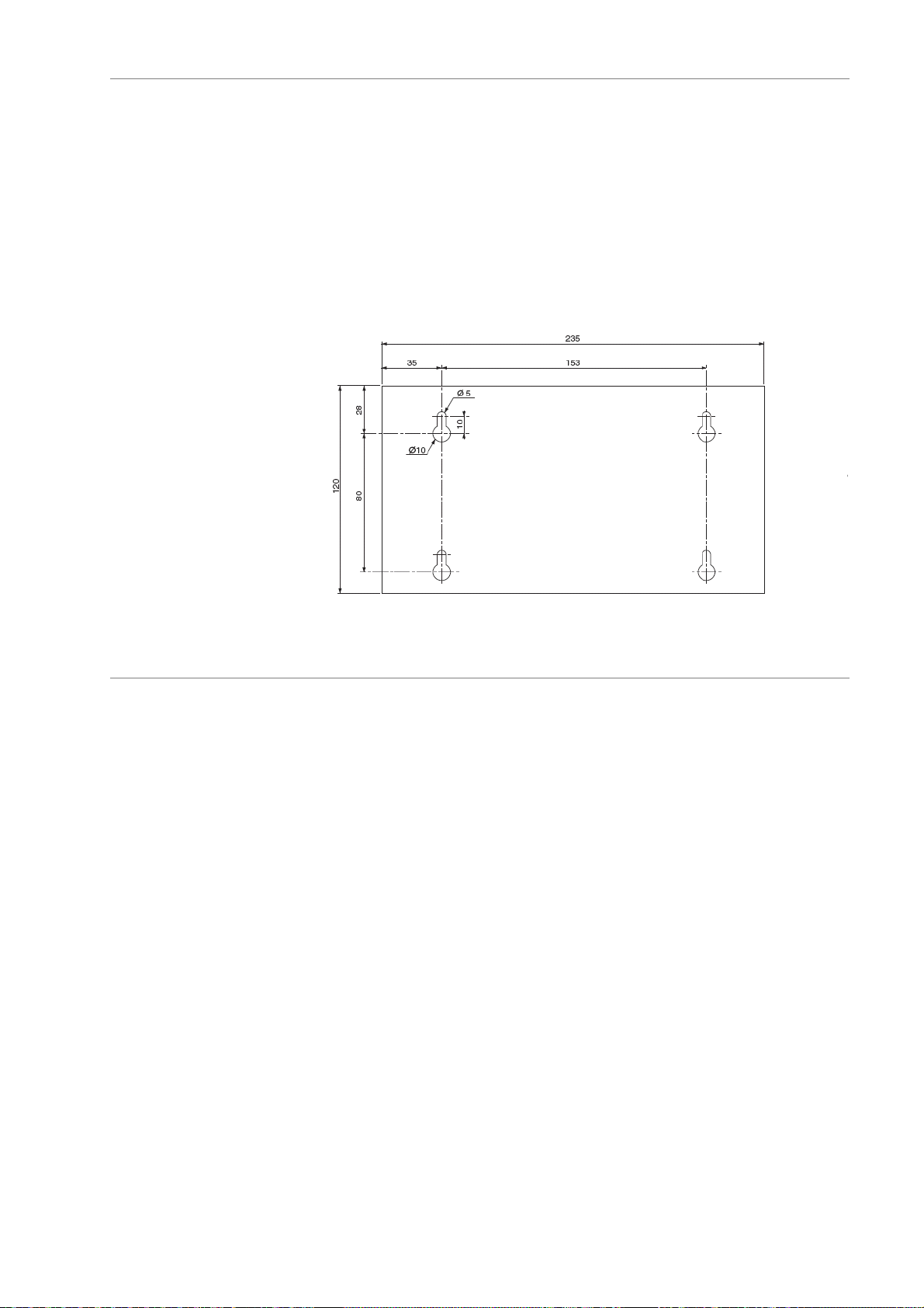
Console mounting
dimensions (mm)
The boards must be installed in a cabinet.
It has dry contacts for displaying three parameters: unit operation, sensor faults
and fan stage faults.
For units with a motherboard and a daughterboard. It has dry contacts for
displaying two parameters: sensor faults and fan stage faults.
Used to view and control the operation of the unit from a distance.
Maximum distance of 1000 m.
Must be installed indoors.
Height = 55
Electrical connections
General
Communication bus
connection
On/Off input
connections
(automatic operation
control, manual override,
changeover of two
setpoints)
Analogue output
connections
Single-pair shielded cable required. Capacitance between wire and shield:
120 pF/m – Resistance of 56 Ω/km.
Examples: Filotex FMA 2P or Filotex IBM 7 362 211.
The shield must be connected at each end to the 0 V line (terminal 3 on J13 or
J12) on the units and the earth to the PLC end. The shielding braid must be as
short as possible (2 cm max.).
The cables must be routed at a distance of at least 30 cm from the power
cables. However, if a power cable intersects with a computer cable, they must
do so at a right angle.
For distances of less than 30 metres, use a shielded cable and keep it at least
30 cm away cm from all lines that could generate interference.
For distances of over 30 metres, install a relay for each input near the board.
Signal output of 0/10 V. Minimum VFD input impedance of 1 kΩ. Shielded cable
connections. Shield connected at both ends to earth. Minimum cross-section of
0.32 mm
2
(1.5 mm2 max.).
On/Off output
connections
(General operation signal,
general fault signal)
Potential-free dry contacts. Maximum current of 10 A (AC1 load), minimum of
5 mA. Voltage of 12 to 230 V AC. Maximum connection cross-section of
2.5 mm
2
.
EN - 10
Page 11
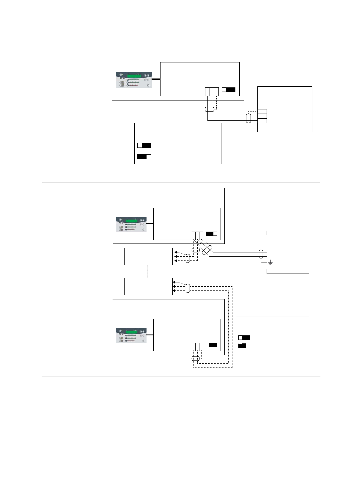
Electrical connections (continued)
pp
p
A
A
)
oca
A
A
(
A
A
Connection
diagram
Link with CIAT chiller
BMS link
Pupitre local
Local console
PPAREIL
UNIT
EROCONNECT
Carte AEROCONNECT
J11
Position of line termination
Position du commutateur de
resistance switch
résistance de fin de ligne W1
on
off
Position of W1 if AeroConnect is
Position W1 si aéroconnect est le
last unit in link
dernier a
Position W1 si aéroconnect n’est
Position of W1 if AeroConnect is
as le dernier appareil de la liaison
not last unit in link
PPAREIL N°1
UNIT No. 1
W1
areil de la liaison
J13
W1
B (-)
A(+)
Board
Carte
Chiller
Groupe de froid
3
J12 Connect
2
JA11 XtraConnect
1
Local console
Pupitre l
Pupitre local
Local console
UNIT NO.
APPAREIL
2
N°2
UNIT No.
APPAREIL
(X-1)
N°
X-1)
l
EROCONNECT board
Carte AEROCONNECT
J11
J13 borne 3
J13 terminal 3
J13 terminal 1
J13 borne 1
J13 terminal 2
J13 borne 2
J13 borne 3
J13 terminal 3
J13 terminal 1
J13 borne 1
J13 terminal 2
J13 borne 2
PPAREIL N°X
UNIT No. X
Carte AEROCONNECT
J11
J13
W1
1 2 3
EROCONNECT board
W1
J13
1 2 3
B(A(+)
RS485 2 fils
2-wire RS485
Longueur max
(Max length:
1000m
1000 m)
Position du commutateur de
Position of line termination
résistance de fin de ligne W1
on
off
Automate ou PC
PLC or PC
sortie RS485
RS485 output
resistance switch W1
Position of W1 on last unit
Position W1 sur le dernier appareil
Position of W1 on the other units
Position W1 sur les autres appareils
EN - 11
Page 12
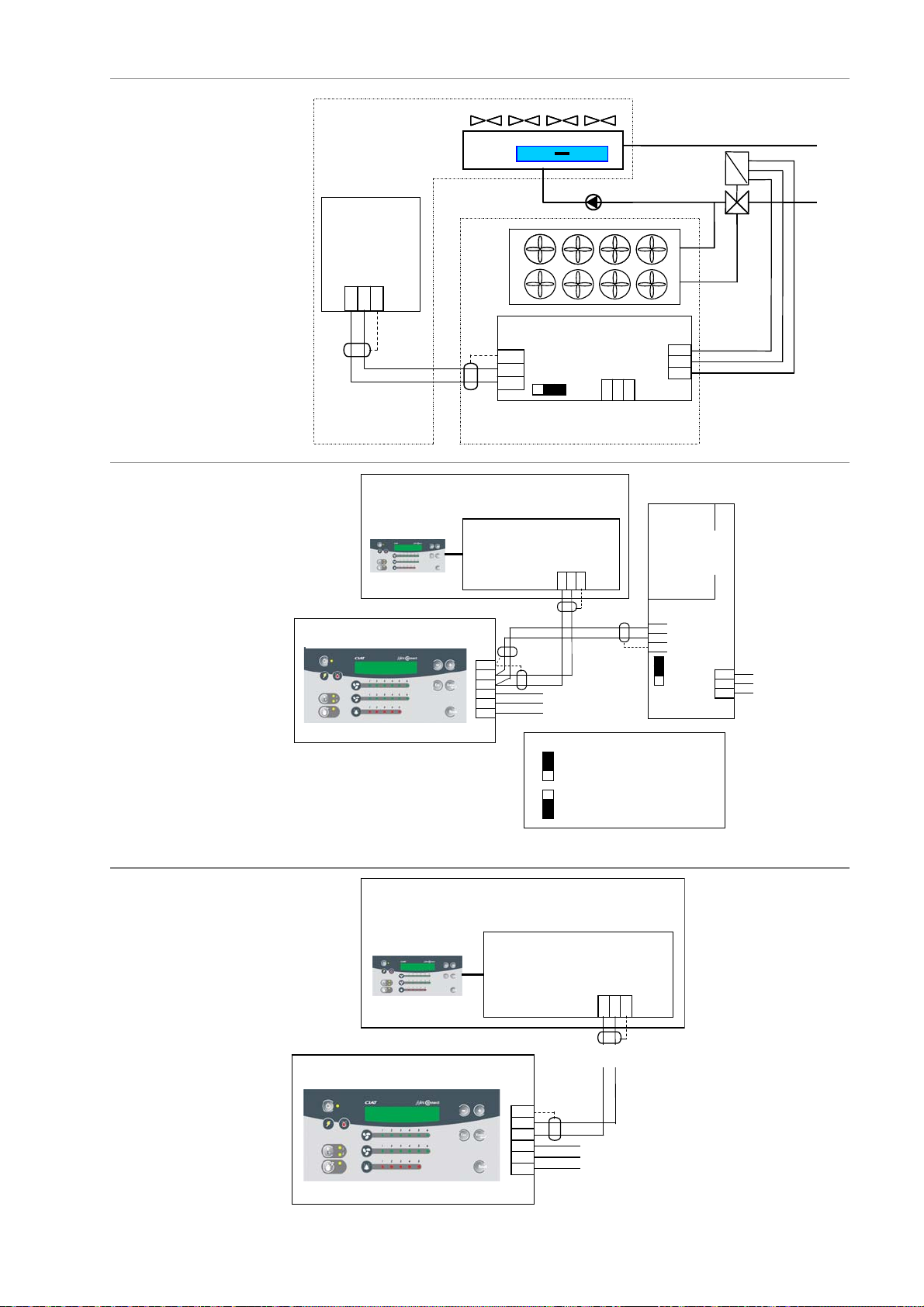
Electrical connections (continued)
)
A
)A (+)
A
)
A
)
)A (+)
3
3
(Op
(
Connection
diagram
Free Cooling
Relay boards
Groupe de froid
Board
Connect J12
Xtraconnect JA11
1 2 3
Chiller
Carte
Pupitre local
Local console
B (-)
A(+
AEROCONNECT board
Carte AEROCONNECT
3
J13
2
1
UNIT
PPAREIL
AEROCONNECT board
Carte AEROCONNECT
J11
P
W1
1 2 3
éroréfrigérant
Dry cooler
J12
J10
Additional
Carte relais
additionnelle
relay
15
14
1 3
board
tion)
(option)
Remote control
console
Remote control console (option)
Pupitre déporté(Option
Local console
Pupitre local
Remote control console (option)
Pupitre déporté(Option
J1
0V
UNIT
B (-
E
Alimentatio n
N
L
Ph
Position of switch if relay board with
Position du switch s i la carte relais est
remote control console option
avec l’option pupitre déporté
Position of switch if relay board without
Position du switch s i la carte relais est
remote control console option,
sans l’option pupitre déporté,
(Raccordement sur aéro connect)
PPAREIL
AEROCONNECT board
Carte AEROCONNECT
J11
J1
0V
J1
Carte relais
1
2
Voir
See
détail
inset
230 V / 50 Hz
230V 50Hz
supply
INSET
DETAIL
Connection to AeroConnect)
J12
230 V / 50 Hz
supply
B (-
Basic relay
board
de base
(option)
(Option)
J5
2
1
E
N
L
Ph
Alimentation
230 V / 50 Hz
230V 50Hz
supply
E
T
230 V / 50 Hz
Alimentation
N
N
supply
230V 50Hz
L
Ph
EN - 12
Page 13
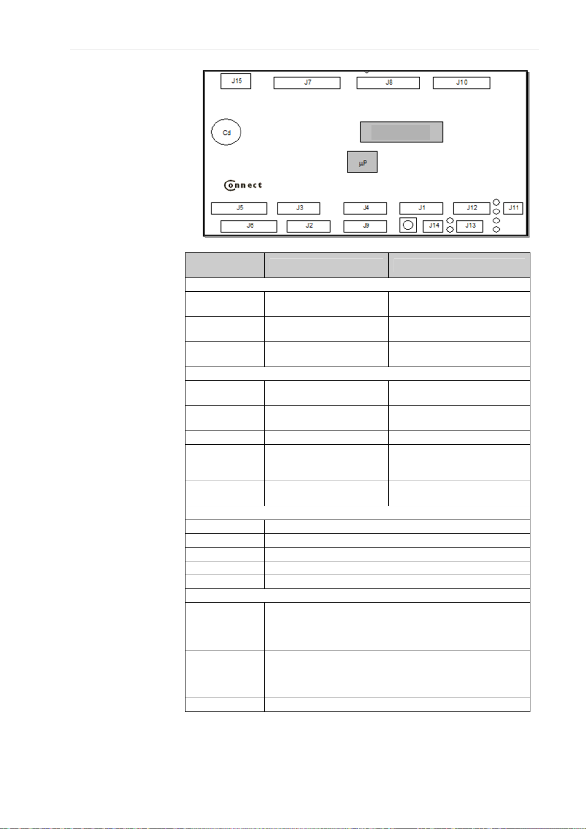
Electrical connections (continued)
Board connections
Motherboard
The structure of the motherboard is illustrated in the diagram below:
Memory
CONNECTOR /
TERMINALS
J6 terms. 1-2
J6 terms. 2-3 Fan manual override
J6 terms. 4-5
J7 terms. 1-2 Operation signal
J7 terms. 3-4 Fault signal
J8 terms. 1-2
J10 terms. 4-5
J2 terms. 1-2 Temperature sensor, coil 1, circuit 1
J2 terms. 2-3 Temperature sensor, coil 1, circuit 2
J3 terms. 1-2 Outdoor temperature sensor.
J3 terms. 2-3 Temperature sensor, coil 2, circuit 1
J3 terms. 4-5 Temperature sensor, coil 2, circuit 2
J12 terms. 1-2-3
J13 terms. 1-2-3
DESCRIPTION DIRECTION OF ACTION
On/Off inputs
Automatic operation
control
Setpoint 1 / Setpoint 2
selection
On/Off outputs
Chiller in free cooling
mode
Free cooling three-way
valve control
Analogue inputs
Bus power supply connected by shielded cable to J1 on
relay board or J1 on remote control console (terminal 1 to
terminal 1, terminal 2 to terminal 2 and the shield to
terminals 3).
Bus power supply connected by shielded cable to J12 on
the CONNECT board, or JA11 on the XTRACONNECT
board (terminal 1 to terminal 1, terminal 2 to terminal 2
and the shield to terminals 3) or the customer BMS.
The machine stops when the
contact opens
The fans turn on when the
contact closes
Setpoint 2 is enabled when
the contact is closed
The contact closes when the
unit is on
The contact opens when a
fault appears
The authorisation is sent to
the chiller when the contact
closes
See wiring diagram
EN - 13
Page 14
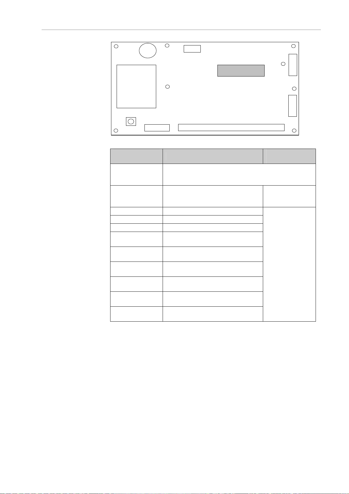
Electrical connections (continued)
Board connections
Basic relay board
To be installed by the customer in his main electrical cabinet.
CONNECTOR /
TERMINALS
Cd
J1
J2J5
DESCRIPTION
Mémoire
Memory
Bus power supply connected by shielded cable to J12
J1 terms. 1-2-3
on AeroConnect board (terminal 1 to terminal 1, terminal
2 to terminal 2 and the shield to terminals 3).
J5 terms. 1-2-3
Single-phase 230 V power supply.
(L - N T)
J2 terms. 1-2 Unit running
J2 terms. 3-4 Sensor fault, coil 1, circuit 1
J2 terms. 5-6 Sensor fault, coil 2, circuit 1
J2 terms. 7-8
J2 terms. 9-10
J2 terms. 11-12
J2 terms. 13-14
J2 terms. 15-16
J2 terms. 17-18
Fan fault, stage 1 / Fan fault,
stage 1, line 1
Fan fault, stage 2 / Fan fault,
stage 2, line 1
Fan fault, stage 3 / fan fault,
stage 3, line 1
Fan fault, stage 4 / fan fault,
stage 4, line 1
Fan fault, stage 5 / fan fault,
stage 5, line 1
Fan fault, stage 6 / fan fault,
stage 6, line 1
J3
J4
DIRECTION OF
ACTION
Term. 1 Neutral
Term. 2 Live
Term. 3 Earth
The contacts are
closed when the
unit is running
without any
faults.
EN - 14
Page 15
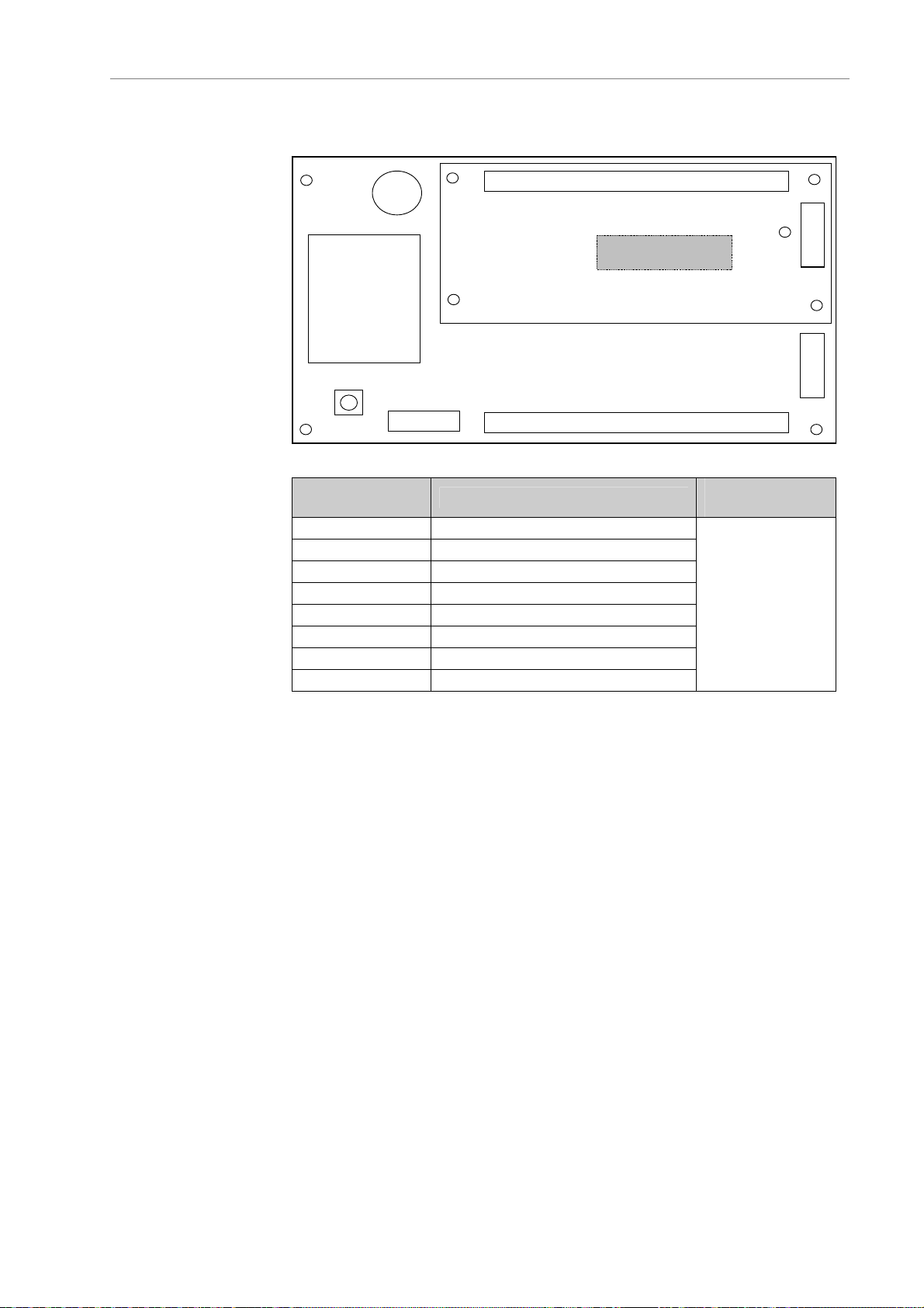
Electrical connections (continued)
Board connections
Additional relay board
Its dry contacts allow the following parameters to be viewed from a distance:
To be installed on the main board by the customer.
Cd
J8
Mémoire
Memory
J2J5
CONNECTOR /
TERMINALS
DESCRIPTION
DIRECTION OF
ACTION
J8 terms. 19-20 Sensor fault, coil 1, circuit 2
J8 terms. 21-22 Sensor fault, coil 2, circuit 2
J8 terms. 23-24 Fan fault, stage 1, line 2
J8 terms. 25-26 Fan fault, stage 2, line 2
J8 terms. 27-28 Fan fault, stage 3, line 2
J8 terms. 29-30 Fan fault, stage 4, line 2
The contacts are
closed when the
unit is running
without any
faults.
J8 terms. 31-32 Fan fault, stage 5, line 2
J8 terms. 33-34 Fan fault, stage 6, line 2
J3
J4
EN - 15
Page 16
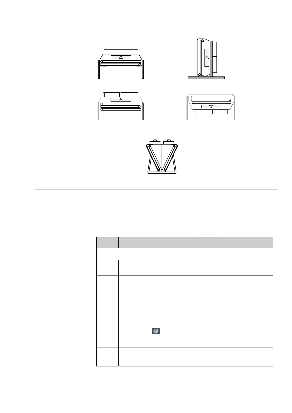
DRY COOLER configuration
Configurations
Flatbed unit
V-type unit
Application: dry cooler with one or two coils
(Induced draught)
Coil 2
Coil 1
Coil 2
Coil 1
(Forced draught)
Commissioning
and configuration
n Turning on the unit:
The screen displays "machine off - on/off" in the [2-Machine status] menu
Press ESC to go back to the menu list.
o Main parameters to be set: select the [5-Settings parameters] menu.
For information on navigating, go to the Control console / Navigation section.
Parameter
No.
A100 Language FR
A103 Control mode: local or remote local
A104 Communication mode (baud) 9600 BMS
A105 Bus number 1 BMS
A110 Stage runtime balancing yes Control = On/Off (stages) or
A111 Free cooling no V-type or 1-coil unit/flatbed
A112
A113 Optimisation of water or electricity
A116 Link with CIAT chiller yes
A120 No. of setpoints per coil 1
Selection air temperature
The parameter is disabled if set to a value of
less than 5. Press to re-enable it.
consumption
Description
Menu 5: Settings parameters
Default
values
mixed
unit without spray
10 Free cooling
Water
optimisation
Spray
Display conditions
EN - 16
Page 17
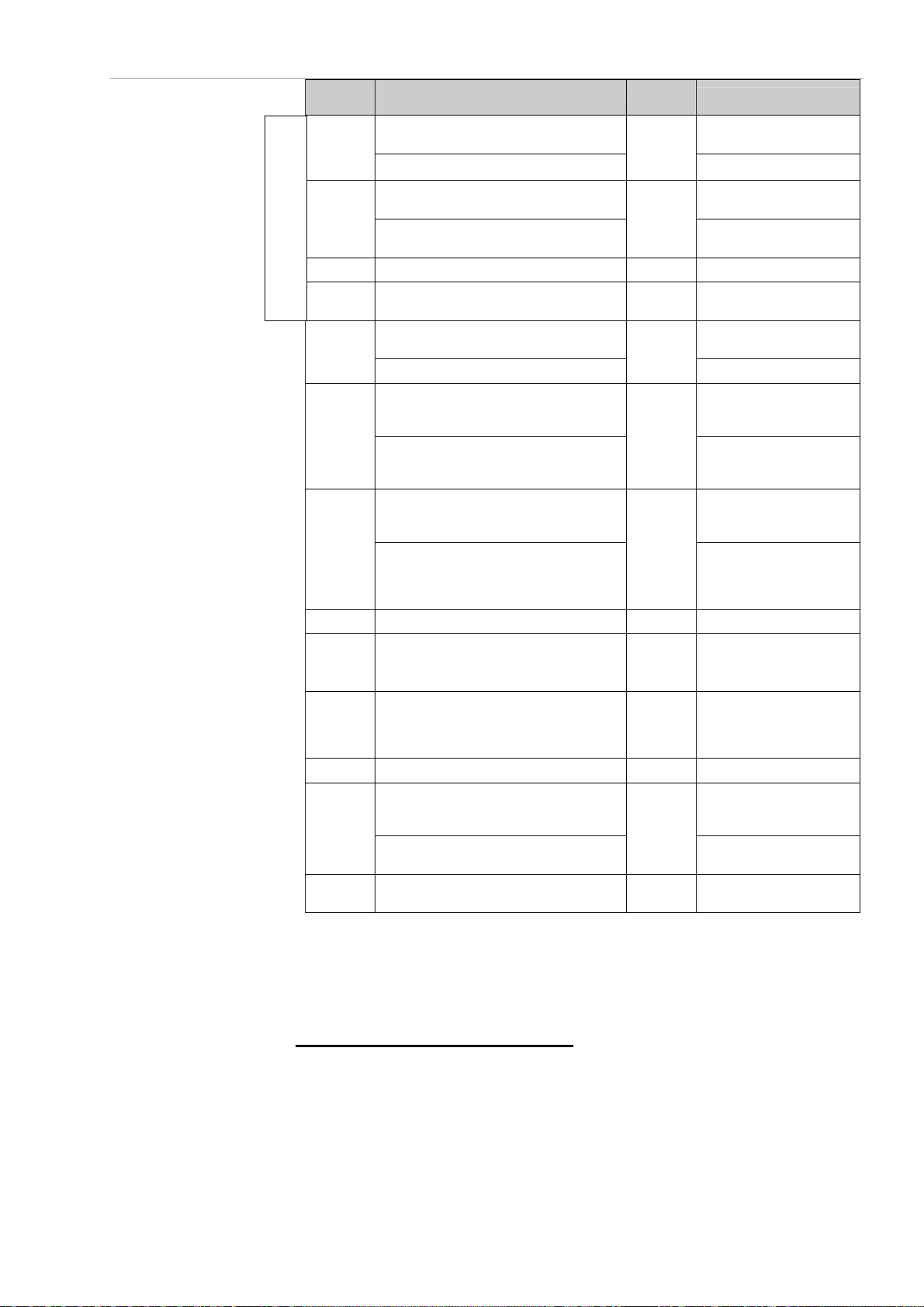
DRY COOLER configuration (continued)
Parameter
No.
Setpoint 1 V-type or 1-coil unit/flatbed
A121
Setpoint 1, coil 1
Setpoint 2 2 setpoints + V-type or 1-coil
A122
with CIAT chillers
A125 Setpoint 1, coil 2 60°C 2 coils/flatbed unit
A126 Setpoint 2, coil 2 50°C
Not available in free cooling mode
A150
A151
A152
to A160
A172 Stage 1 hysteresis, coil 2: 1 to 20°C 5°C 2 coils/flatbed unit
A173
A174
to A182
A199 Outdoor spray temperature 35°C Spray / elec. optimisation
A200
A202 Spray stage difference, coil 2 2°C Spray / water optimisation +
Setpoint 2, coil 1
Stage 1 hysteresis: 1 to 20°C V-type or 1-coil unit/flatbed
Stage 1 hysteresis, coil 1: 1 to 20°C
Difference between stages 1 and 2:
1 to 5°C
Difference between stages 1 and 2 of
coil 1: 1 to 5°C
Hysteresis of stages 2, 3, 4, 5 or 6:
1 to 10°C
Delta of stages 2, 3, 4, 5 or 6: 1 to 5°C
Hysteresis of stages 2, 3, 4, 5 and 6 of
coil 1: 1 to 10°C
Delta of stages 2, 3, 4, 5 and 6 of coil 1: 1
to 5°C
Difference between stages 1 and 2 of
coil 2: 1 to 5°C
Hysteresis of stages 2, 3, 4, 5 and 6 of
coil 2: 1 to 10°C
Delta of stages 2, 3, 4, 5 and 6 of coil 2:
1 to 5°C
Spray stage difference Spray / water optimisation +
Spray stage difference, coil 1
Default values Default
values
60°C
50°C
5°C
2°C
5°C
2°C
Control = On/Off + based on
2°C
Display conditions
unit
2 coils + flatbed unit
unit/flatbed unit
2 setpoints + 2 coils/flatbed
unit
2 setpoints + 2 coils/flatbed
unit
unit
2 coils/flatbed unit
Control = On/Off + No. of
stages ≥ 2 + V-type or 1-coil
unit/flatbed unit
Control = On/Off + No. of
stages ≥ 2 +2 coils/flatbed
unit
Control = On/Off + based on
No. of stages + V-type or
1-coil unit/flatbed unit
Control = On/Off + based on
No. of stages +2 coils/flatbed
unit
Control = On/Off + No. of
stages ≥ 2 +2 coils/flatbed
unit
No. of stages +2 coils/flatbed
unit
V-type or 1-coil unit/flatbed
unit
Spray / water optimisation +
2 coils/flatbed unit
2 coils/flatbed unit
p Turning on the unit: Power button
To change the setpoint values rapidly
EN - 17
: go directly to the [1- Setpoint] menu.
Page 18
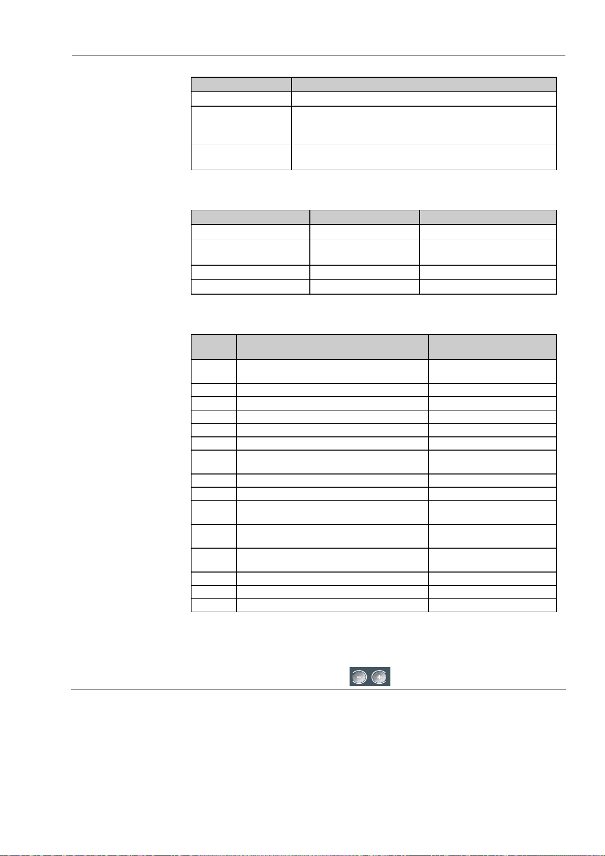
DRY COOLER configuration (continued)
Information
available while the
unit is running
[2-Machine status] menu: appears if the control console is not used for one hour.
Fault Information
No faults Setpoint and measurement values displayed.
Sensor fault
The general fault LED and measurement fault LED
flash and a message appears stating which sensor is
faulty and the terminal references
Fan fault
The general fault LED and stage status LED flash and
a message appears stating which stage is faulty
[3-Measured values] menu:
Parameter Description Display conditions
Outdoor temperature Value displayed Free cooling or spray
Coil temperature Value displayed
V-type or 1-coil unit/
Flatbed unit
Coil 1 temperature Value displayed 2 coils/flatbed unit
Coil 2 temperature Value displayed 2 coils/flatbed unit
[6-Reading parameters] menu:
Parameter
No.
A250
A252 Outdoor air temperature Free cooling or spray
A253 Value of coil 1 setpoint
A255 Value of coil 2 setpoint 2 coils/flatbed unit
A257 Value of coil 1 temperature
A261 Value of coil 2 temperature 2 coils/flatbed unit
A270 to
A275
A299 Spray time Spray
A300 Free cooling time Free cooling
A400 to
A421
A430 to
A451
A460 Fan speed in %
A555 CPU board version No.
A556 Control console version No.
A557 Daughter board version No.
LED test: press Enter to check the operation
of the LEDs
Running time of each stage
Status (open or closed) of the logic inputs on
the board
Status (open or closed) of the logic outputs
on the board
Description Display conditions
Control = mixed or speed
control
The [7-Fault memory] menu contains the nine most recent faults on the fan
stages or outdoor temperature sensors.
To scroll through the faults, press .
EN - 18
Page 19
DRY COOLER configuration (continued)
Factory-set
parameters
[4-Machine
parameters]
menu
The [4-Machine parameters] menu contains the parameters used to configure
the machine. They were set in the factory and are locked. The symbol
appears at the top left of the screen.
In certain rare cases (such as adding the spray function) it may be necessary to
update a parameter. The parameters may be unlocked by changing parameter
A99. However, do not modify any parameters other than those that require
changing.
Parameter
No.
A01 Unit type (flatbed or V-coil)
A02
A03
A05
A07
Parameter description Display condition
Number of coils (1 or 2) Flatbed unit
Parallel coil (yes) V-type unit
Coil type 1 (1 LP or HT water
circuit)
Coil type 2 (1 LP or HT water
circuit)
Control type: On/Off (stages),
speed control or mixed
2 coils/flatbed unit
A08 Number of stages (1 to 6)
A10 Spray (yes or no)
A99 Lock parameters (yes)
Control = On/Off or
mixed
EN - 19
Page 20
CONDENSER configuration
Configurations
Flatbed unit
V-type unit
Commissioning
and configuration
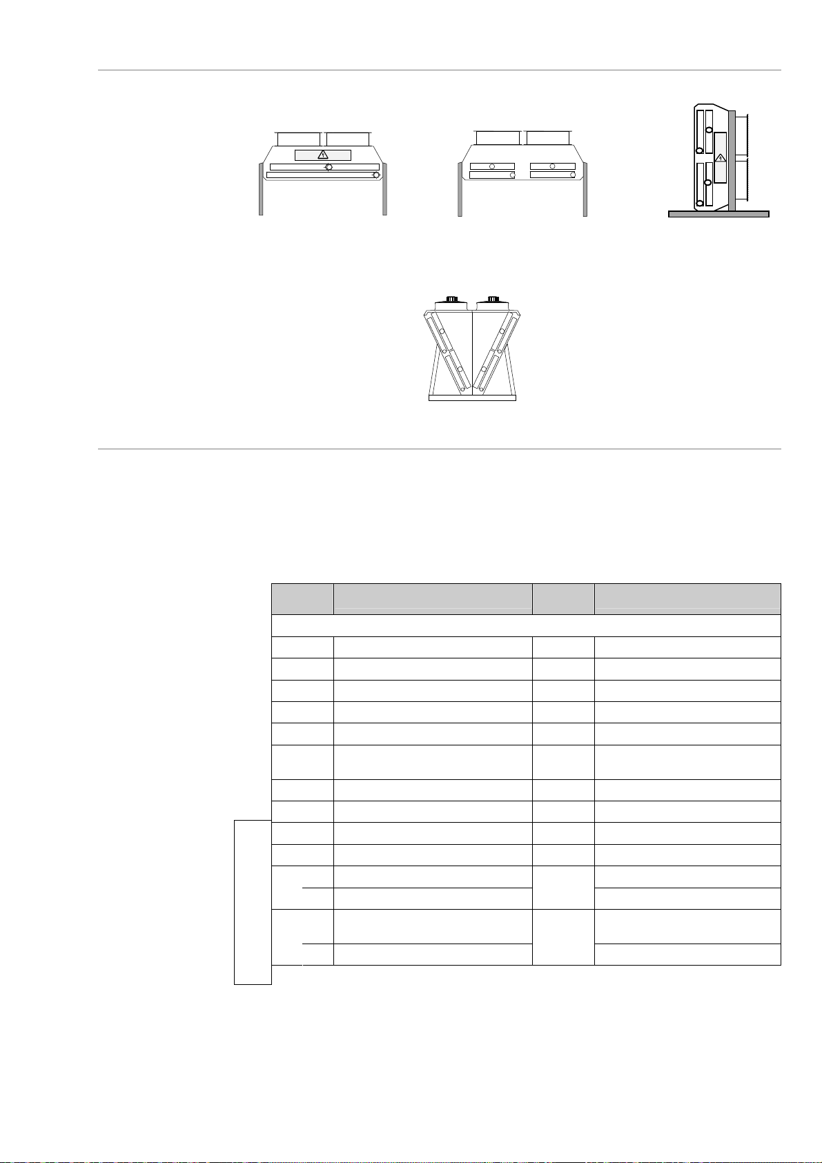
Application: condenser with one or two refrigerant circuits
Line 1 Line 2
Circuit 1
1 refrigerant
Circuit 1 Circuit 2
circuit
Circuit 2
Line 1 Line 2
2 refrigerant circuits
Coil 1
Coil 2
n Turning on the unit:
The screen displays "machine off - on/off" in the [2-Machine status] menu.
Press ESC to go back to the menu list.
o Main parameters to be set: select the [5-Settings parameters] menu.
For information on navigating, go to the Control console / Navigation section.
Parameter
No.
A100 Language FR
A103 Control mode: local or remote local
A104 Communication mode (baud) 9600 BMS
A105 Bus number 1 BMS
A110 Stage runtime balancing yes Control = On/Off (stages) or mixed
A113 Optimisation of water or electricity
A116 Link with CIAT chiller yes
A120 No. of setpoints per circuit or coil 1
A121 Setpoint 1, circuit or coil 1 12 bar
A122 Setpoint 2, circuit or coil 1 12 bar 2 setpoints
or
or
Not available for CIAT chillers
consumption
A123 Setpoint 1, circuit 2 2 refrigerant circuits + flatbed unit
A125 Setpoint 1, coil 2
Setpoint 2, circuit 2 2 setpoints & 2 refrigerant circ. +
A124
A126 Setpoint 2, coil 2
Description
Menu 5: Settings parameters
Default
values
Water
optimisation
12 bar
12 bar
Display conditions
Spray
V-type unit
flatbed unit
2 setpoints + V-type unit
EN - 20
Page 21
CONDENSER configuration (continued)
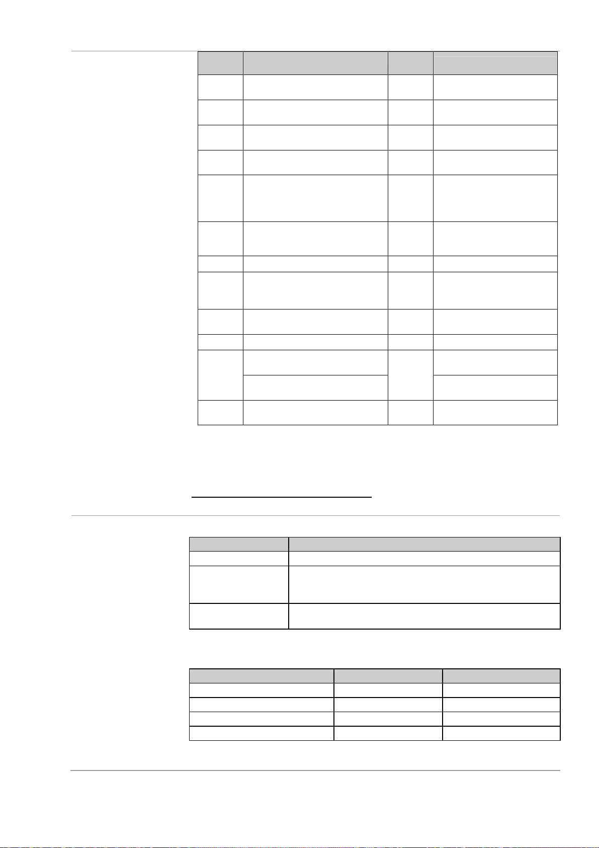
Parameter
No.
A150 Stage 1 hysteresis, circuit or coil 1:
A151 Difference between stages 1 and 2,
A152 to
A160
A161
A162
A163 to
A171
A172 Stage 1 hysteresis, coil 2: 2 to 6 bar 3.5 bar Flatbed unit
A173 Difference between stages 1 and 2,
A174 to
A182
A199 Outdoor spray temperature 35°C Spray / elec. optimisation
A200
A201 Spray stage difference, circuit or
2 to 6 bar
circuit or coil 1: 0.5 to 3 bar
Hysteresis and difference of stages
2, 3, 4, 5 or 6, circuit or coil 1
Stage 1 circuit 2 hysteresis:
2 to 6 bar
Difference between stages 1 and 2,
circuit 2: 0.5 to 3 bar
Hysteresis and difference of stages
2, 3, 4, 5 or 6, circuit 2
coil 2: 0.5 to 3 bar
Hysteresis and difference of stages
2, 3, 4, 5 or 6, coil 2
Spray stage difference Spray / water optimisation & 1
Spray stage difference, circuit or
coil 1
coil 2
Default values Default
values
3.5 bar
0.5 bar Control = On/Off + No. of stages
3.5 bar
3.5 bar 2 refrigerant circuits + flatbed unit
0.5 bar
3.5 bar Control = On/Off + based on No.
0.5 bar
3.5 bar Control = On/Off + based on No.
0.5 bar
0.5 bar Spray / water optimisation & 2
Display conditions
≥2
Control = On/Off + based on No.
of stages
Control = On/Off + No. of stages
≥2
+ 2 refrigerant circuits + flatbed
unit
of stages + 2 refrigerant circuits +
flatbed unit
Control = On/Off + No. of stages
≥2
+ V-type unit
of stages + V-type unit
refrigerant circuit
Spray / water optimisation & 2
refrigerant circuits
refrigerant circuits
Information
available while the
unit is running
p Turning on the unit: Power button
To change the setpoint values rapidly
[2-Machine status] menu: appears if the control console is not used for one hour.
Fault Information
No faults setpoint and measurement values displayed.
Sensor fault
The general fault LED and measurement fault LED flash
and a message appears stating which sensor is faulty
and the terminal references
Fan fault
The general fault LED and stage status LED flash and a
message appears stating which stage is faulty
[3-Measured values] menu:
Parameter Description Display conditions
Outdoor temperature Value displayed Spray
COIL PRESSURE Value displayed 1 refrigerant circuit
Pressure, circuit or coil 1 Value displayed 2 refrigerant circuits
Pressure, circuit or coil 2 Value displayed 2 refrigerant circuits
: go directly to the [1- Setpoint] menu.
EN - 21
Page 22
CONDENSER configuration (continued)
Information
available while the
unit is running
(continued)
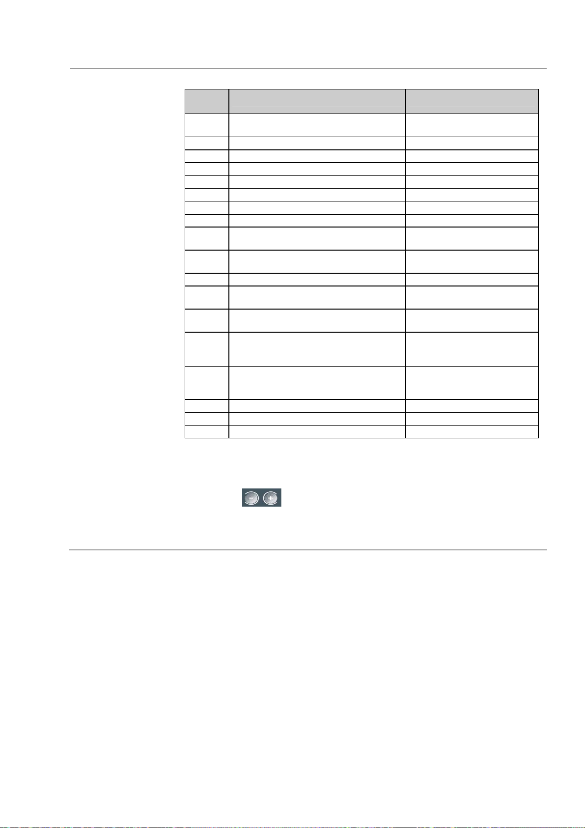
[6-Reading parameters] menu:
Parameter
No.
A250
A252 Outdoor air temperature Spray
A253 Value of circuit or coil 1 setpoint
A254 Value of circuit 2 setpoint 2 refrig. circuits + flatbed unit
A255 Value of coil 2 setpoint V-type unit
A258 Value of circuit or coil 1 pressure
A260 Value of circuit 2 pressure 2 refrig. circuits + flatbed unit
A262 Value of coil 2 pressure V-type unit
A270 to
A275
A280 to
A295
A299 Spray time Spray
A400 to
A421
A430 to
A451
A460 If 1 refrigerant circuit = Fan speed in %
A461 Speed (in %) of fans on line 2
A555 CPU board version No.
A556 Control console version No.
A557 Daughter board version No.
LED test: press Enter to check the
operation of the LEDs
Running time of each stage 1 refrigerant circuit or 1 fan line
Running time of each stage on each line
Status (open or closed) of the logic inputs
on the board
Status (open or closed) of the logic
outputs on the board
If 2 refrigerant circuits and 2 fan lines =
Line 1 fan speeds
Description Display conditions
2 refrigerant circuits + 2 fan
lines
Control = mixed or speed
control
Control = mixed or speed
control + 2 refrigerant circuits +
2 fan lines
The [7-Fault memory] menu contains the nine most recent faults on the fan
stages, pressure sensors or outdoor temperature sensor. To scroll through the
faults, press .
EN - 22
Page 23
CONDENSER configuration (continued)
Factory-set
parameters
[4-Machine
parameters]
menu
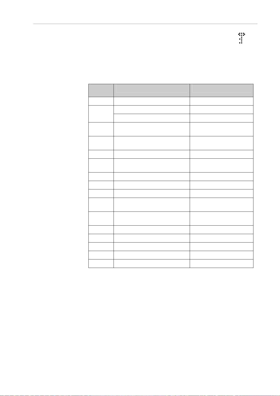
The[4-Machine parameters] menu contains the parameters used to configure
the machine. They were set in the factory and are locked. The symbol
appears at the top left of the screen.
In certain rare cases (such as adding the spray function) it may be necessary to
update a parameter. The parameters may be unlocked by changing parameter
A99. However, do not modify any parameters other than those that require
changing.
Parameter
No.
A01 Unit type (flatbed or V-coil)
A02
A03
A04
A05 Coil 2 type (1 refrigerant circuit) V-type unit
A07
Parameter description Display condition
Number of coils (1) Flatbed unit
Parallel coil (no) V-type unit
Coil 1 type (1 refrigerant circuit, 2
refrigerant circuits)
Coil circuit type (balanced or
unbalanced)
Control type: On/Off (stages),
speed control or mixed
Flatbed unit & 2 refrigerant
circuits
A08 Number of stages (1 to 6) Control = On/Off or mixed
A09 Number of fan lines (1 or 2) Flatbed unit & 2 refrig. circ.
A10 Spray (yes or no)
A30
A31
A32 Top of sensor range - circuit 2 2 refrigerant circuits
A33 Bottom of sensor range - circuit 2 2 refrigerant circuits
A34 Top of sensor range - coil 2 2 refrigerant circuits
A35 Bottom of sensor range - coil 2 2 refrigerant circuits
A99 Lock parameters (yes)
Top of sensor range - circuit or
coil 1
Bottom of sensor range - circuit or
coil 1
EN - 23
Page 24
BMS communication protocol
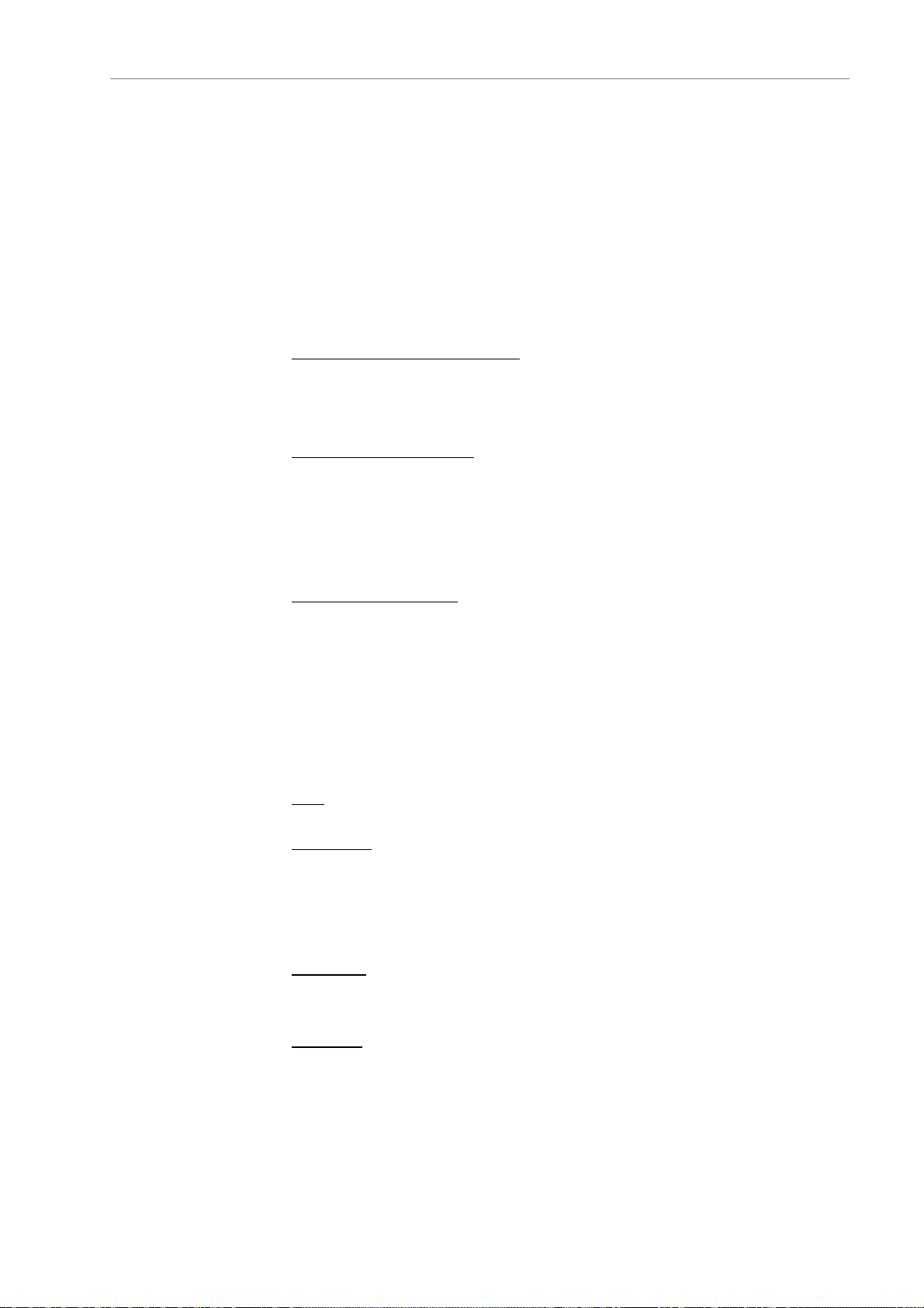
Communication
interface
Transmission
mode
RS485
3-pin connector, terminal block J13: Terminal 1: A or +
Terminal 2: B or –
Terminal 3: for a shield
The line termination resistance can be configured with jumper W1:
Two lights provide information on the status of the transmission of date:
- D11: incoming light. Usually off; flashes when a message is received by
the board. If this light is continuously on, the bus is reversed. In this
case, swap terminals 1 and 2 on J9.
- D14: outgoing light. Usually off; lights up when the CPU sends a
message over the bus.
Serial, asynchronous, half duplex
- 1 start bit, 8 data bits, no parity bits, 1 stop bit.
- The bit rate can be set in parameter P104 to 4800 baud or
9600 baud.
Analogue value endcoding
Standard IEEE 32-bit format (2 registers)
Order of values:
- if P108 = 9600 or 4800 low order, high order
- if P108 = Jbus high order, low order
Remote signalling
register
(read-only)
Codes of functions used
1 or 2: read n bits
3 or 4: read multiple registers (16 bits)
5: write one bit
6: write register function
8: read diagnostics counters
11: read event counter
15: write n bits
16: write multiple registers (16 bits)
Note
: Functions 15 and 16 are possible if parameter P103 is set to "Remote,
BMS…"
Error codes
:
1 function code unknown
2 wrong address
3 data error
Register 1: Board type
Bits 0 to 7: Board type for AeroConnect = 32
Bits 8 to 15 0
Register 2
: Operating status
Bit 0: On/off (1 = on => on and CA closed)
Bit 1: Spray status 1 = on
Bit 2: Free cooling status 1 = on
EN - 24
Page 25
BMS communication protocol (continued)
Remote alarm
register
(read-only)
Remote
measurement
register
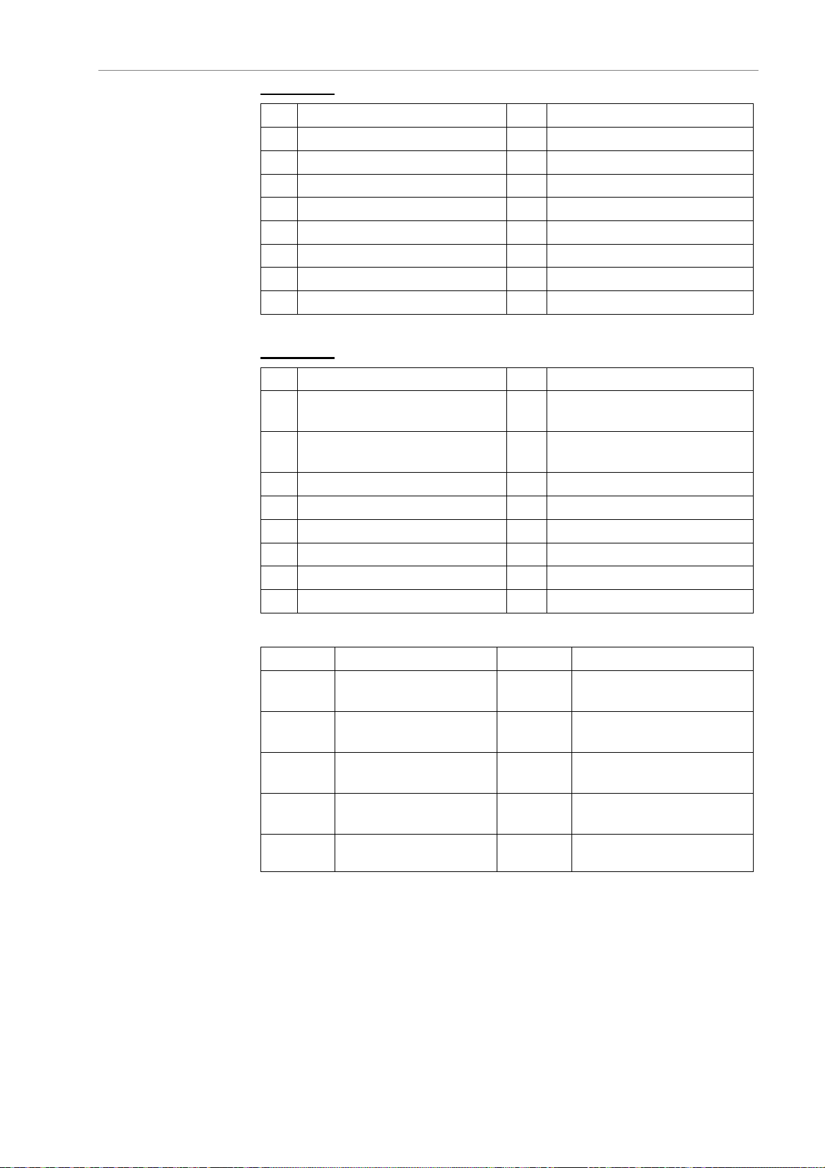
Register 10: FAN FAULTS (1 = fault detected)
Bit Bit
0 Fan fault, stage 1, line 1 8 Fan fault, stage 1, line 2
1 Fan fault, stage 2, line 1 9 Fan fault, stage 2, line 2
2 Fan fault, stage 3, line 1 10 Fan fault, stage 3, line 2
3 Fan fault, stage 4, line 1 11 Fan fault, stage 4, line 2
4 Fan fault, stage 5, line 1 12 Fan fault, stage 5, line 2
5 Fan fault, stage 6, line 1 13 Fan fault, stage 6, line 2
6 N.U.. 14 N.U..
7 N.U. 15 N.U..
Register 11
Bit Bit
0
1
2 N.U. 10 N.U.
3 N.U. 11 N.U.
4 N.U. 12 N.U.
5 N.U. 13 N.U.
6 N.U. 14 N.U..
7 N.U. 15 N.U..
: FAN FAULTS (1 = fault detected)
Sensor or pressure fault, coil 1,
circuit 1
Sensor or pressure fault, coil 1,
circuit 2
Sensor or pressure fault,
8
coil 2, circuit 1
Sensor or pressure fault,
9
coil 2, circuit 2
Registers
100 and
101
Control setpoint, coil 1,
circuit 1
Registers
108 and
109
Temperature or pressure,
coil 1, circuit 1
(read-only)
102 and
104 and
106 and
103
105
107
Control setpoint, coil 1,
circuit 2
Control setpoint, coil 2,
circuit 1
Control setpoint, coil 2,
circuit 2
EN - 25
110 and
111
112 and
113
114 and
115
116 and
117
Temperature or pressure,
coil 1, circuit 2
Temperature or pressure,
coil 2, circuit 1
Temperature or pressure,
coil 2, circuit 2
Outdoor temperature
Page 26

BMS communication protocol (continued)
Fault memory
Register 200: Fault 9 memory
Register 201
Register 202
Register 203
Register 204
Register 205
Register 206
Register 207
Register 208
0: Fault memory empty
0x010: Fan fault, stage 1, line 1
0x011: Fan fault, stage 2, line 1
0x012: Fan fault, stage 3, line 1
0x013: Fan fault, stage 4, line 1
0x014: Fan fault, stage 5, line 1
0x015: Fan fault, stage 6, line 1
0x016: Fan fault, stage 1, line 2
0x017: Fan fault, stage 2, line 2
0x018: Fan fault, stage 3, line 2
0x019: Fan fault, stage 4, line 2
0x01A: Fan fault, stage 5, line 2
0x01B: Fan fault, stage 6, line 2
0x080: Temperature sensor fault, coil 1, circuit 1
0x081: Temperature sensor fault, coil 1, circuit 2
0x082: Temperature sensor fault, coil 2, circuit 1
0x083: Temperature sensor fault, coil 2, circuit 2
0x084: Temperature sensor fault, coil 1, circuit 1
0x085: Temperature sensor fault, coil 1, circuit 2
0x086: Temperature sensor fault, coil 2, circuit 1
0x087: Temperature sensor fault, coil 2, circuit 2
: Fault 8 memory
: Fault 7 memory
: Fault 6 memory
: Fault 5 memory
: Fault 4 memory
: Fault 3 memory
: Fault 2 memory
: Fault 1 memory
Counters
(read-only)
Registers 300 and 301
Registers 302 and 303
Registers 304 and 305
Registers 306 and 307
Registers 308 and 309
Registers 310 and 311
Registers 312 and 313
Registers 314 and 315
Registers 316 and 317
Registers 318 and 319
Registers 320 and 321
Registers 322 and 323
Register 324 to 398
: Fan runtime, stage 1, line 1
: Fan runtime, stage 2, line 1
: Fan runtime, stage 3, line 1
: Fan runtime, stage 4, line 1
: Fan runtime, stage 5, line 1
: Fan runtime, stage 6, line 1
: Fan runtime, stage 1, line 2
: Fan runtime, stage 2, line 2
: Fan runtime, stage 3, line 2
: Fan runtime, stage 4, line 2
: Fan runtime, stage 5, line 2
: Fan runtime, stage 6, line 2
: Reserved
EN - 26
Page 27
BMS communication protocol (continued)
Remote
configuration
register
(read and write)
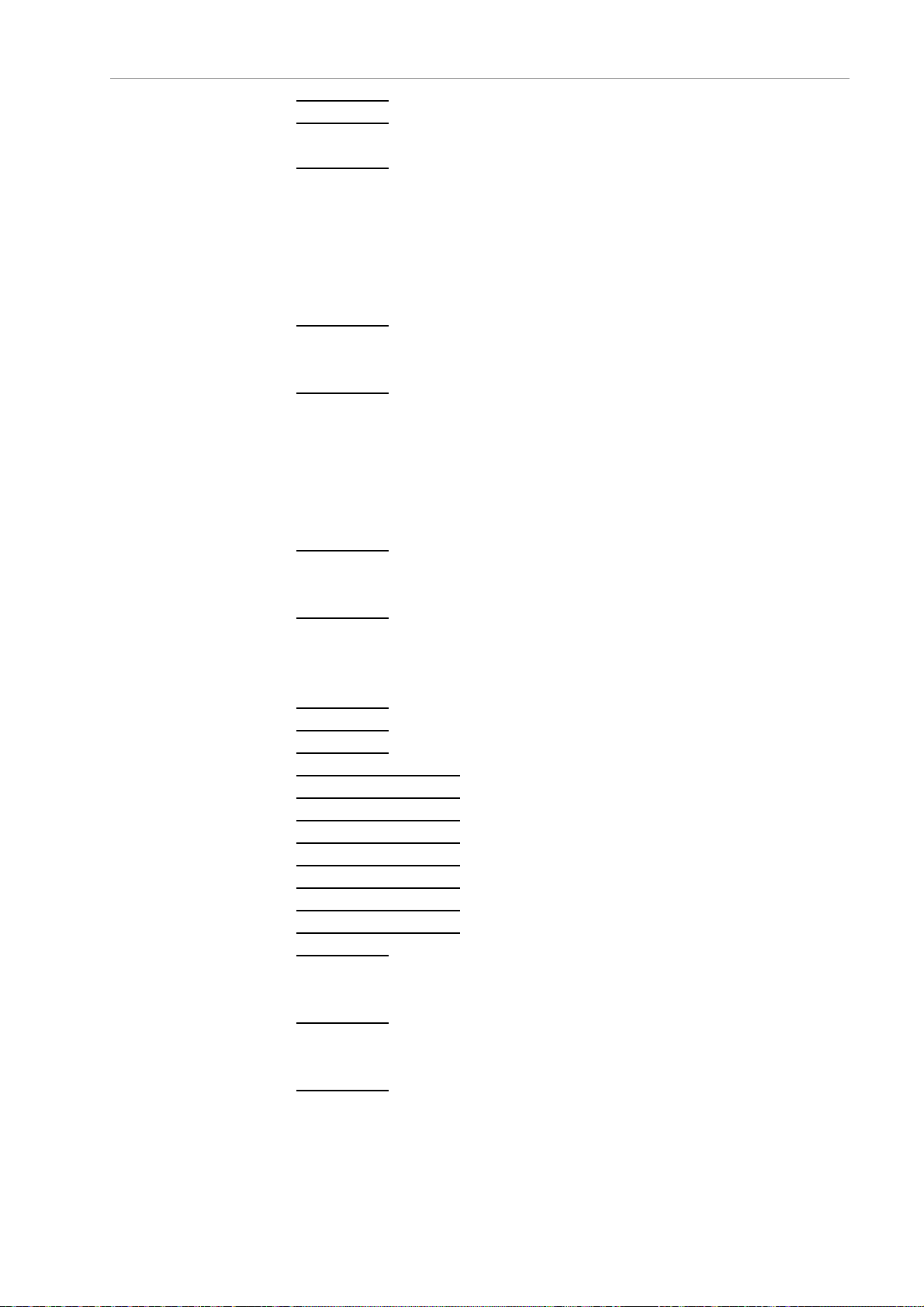
Register 399: Unit type (A01) 0 => Flatbed, 1 => V
Register 400
If A01 = flatbed P02 = number of coils
Register 401
0 => 1 low-temperature water circuit
1 => 2 low-temperature water circuits
2 => 1 high-temperature water circuit
3 => 2 high-temperature water circuits
4 => 1 refrigerant circuit
5 => 2 refrigerant circuits
Register 402
0 => balanced circuit
1 => unbalanced circuit
Register 403
0 => 1 low-temperature water circuit
1 => 2 low-temperature water circuits
2 => 1 high-temperature water circuit
3 => 2 high-temperature water circuits
4 => 1 refrigerant circuit
5 => 2 refrigerant circuits
Register 404
0 => balanced circuit
1 => unbalanced circuit
Register 405
0 => On/Off
1 => speed control
2 => mixed, energy
Register 406
Register 407
Register 408
Registers 409 and 410
Registers 411 and 412
Registers 413 and 414
Registers 415 and 416
Registers 417 and 418
Registers 419 and 420
Registers 421 and 422
Registers 423 and 424
Register 425
0 => no
1 => yes
Register 450
0 => no
1 => yes
Register 451
0 => 1 setpoint
1 => 2 setpoints via BMS or console
2 => 2 setpoints per On/Off input
: If A01 = V type: A02 parallel coil 0 = NO, 1 = YES
: Coil 1 type (A03)
: A04: Circuit type, coil 1
: A05: Coil 2 type
: A06: Circuit type, coil 2
: A07: Type of control
: A08: Number of fan stages
: A09: Number of fan lines
: A10: Spray (0 = NO, 1 = YES)
: A30: High value, HP sensor, coil 1, circuit 1
: A31: Low value, HP sensor, coil 1, circuit 1
: A32: High value, HP sensor, coil 1, circuit 2
: A33: Low value, HP sensor, coil 1, circuit 2
: A34: High value, HP sensor, coil 2, circuit 1
: A35: Low value, HP sensor, coil 2, circuit 1
: A36: High value, HP sensor, coil 2, circuit 2
: A37: Low value, HP sensor, coil 2, circuit 2
: A99: Lock
: A110: Optimised fan operation
: A120: Number of setpoints
EN - 27
Page 28

BMS communication protocol (continued)
Remote
configuration
register (read and
write)
Registers 452 and 453: A121: Setpoint 1, coil 1, circuit 1
Registers 454 and 455
Registers 456 and 457
Registers 458 and 459
Registers 460 and 461
Registers 462 and 463
Registers 464 and 465
Registers 466 and 467
Registers 468 and 469
Registers 470 and 471
Registers 472 and 473
Registers 474 and 475
Registers 476 and 477
Registers 478 and 479
Registers 480 and 481
Registers 482 and 483
Registers 484 and 485
Registers 486 and 487
Registers 488 and 489
Registers 490 and 491
Registers 492 and 493
Registers 494 and 495
Registers 496 and 497
Registers 498 and 499
Registers 500 and 501
Registers 502 and 503
Registers 504 and 505
Registers 506 and 507
Registers 508 and 509
Registers 510 and 511
Registers 512 and 513
Registers 514 and 515
Registers 516 and 517
Registers 518 and 519
Registers 520 and 521
Registers 522 and 523
Registers 524 and 525
Registers 526 and 527
Registers 528 and 529
Registers 530 and 531
Registers 532 and 533
Registers 534 and 535
Registers 536 and 537
Registers 538 and 539
Registers 540 and 541
Registers 542 and 543
Registers 544 and 545
Registers 546 and 547
Registers 548 and 549
: A122: Setpoint 2, coil 1, circuit 1
: A123: Setpoint 1, coil 1, circuit 2
: A124: Setpoint 2, coil 1, circuit 2
: A125: Setpoint 1, coil 2, circuit 1
: A126: Setpoint 2, coil 2, circuit 1
: A127: Setpoint 1, coil 2, circuit 2
: A128: Setpoint 2, coil 2, circuit 2
: A150: Hysteresis, stage 1, coil 1, circuit 1
: A151: Setpoint difference, stage 2, coil 1, circuit 1
: A152: Hysteresis, stage 2, coil 1, circuit 1
: A153: Setpoint difference, stage 3, coil 1, circuit 1
: A154: Hysteresis, stage 3, coil 1, circuit 1
: A155: Setpoint difference, stage 4, coil 1, circuit 1
: A156: Hysteresis, stage 4, coil 1, circuit 1
: A157: Setpoint difference, stage 5, coil 1, circuit 1
: A158: Hysteresis, stage 5, coil 1, circuit 1
: A159: Setpoint difference, stage 6, coil 1, circuit 1
: A160: Hysteresis, stage 6, coil 1, circuit 1
: A161: Hysteresis, stage 1, coil 1, circuit 2
: A162: Setpoint difference, stage 2, coil 1, circuit 2
: A163: Hysteresis, stage 2, coil 1, circuit 2
: A164: Setpoint difference, stage 3, coil 1, circuit 2
: A165: Hysteresis, stage 3, coil 1, circuit 2
: A166: Setpoint difference, stage 4, coil 1, circuit 2
: A167: Hysteresis, stage 4, coil 1, circuit 2
: A168: Setpoint difference, stage 5, coil 1, circuit 2
: A169: Hysteresis, stage 5, coil 1, circuit 2
: A170: Setpoint difference, stage 6, coil 1, circuit 2
: A171: Hysteresis, stage 6, coil 1, circuit 2
: A172: Hysteresis, stage 1, coil 2, circuit 1
: A173: Setpoint difference, stage 2, coil 2, circuit 1
: A174: Hysteresis, stage 2, coil 2, circuit 1
: A175: Setpoint difference, stage 3, coil 2, circuit 1
: A176: Hysteresis, stage 3, coil 2, circuit 1
: A177: Setpoint difference, stage 4, coil 2, circuit 1
: A178: Hysteresis, stage 4, coil 2, circuit 1
: A179: Setpoint difference, stage 5, coil 2, circuit 1
: A180: Hysteresis, stage 5, coil 2, circuit 1
: A181: Setpoint difference, stage 6, coil 2, circuit 1
: A182: Hysteresis, stage 6, coil 2, circuit 1
: A183: Hysteresis, stage 1, coil 2, circuit 2
: A184: Setpoint difference, stage 2, coil 2, circuit 2
: A185: Hysteresis, stage 2, coil 2, circuit 2
: A186: Setpoint difference, stage 3, coil 2, circuit 2
: A187: Hysteresis, stage 3, coil 2, circuit 2
: A188: Setpoint difference, stage 4, coil 2, circuit 2
: A189: Hysteresis, stage 4, coil 2, circuit 2
: A190: Setpoint difference, stage 5, coil 2, circuit 2
EN - 28
Page 29

BMS communication protocol (continued)
Remote
configuration
register (read and
write)
Function 1, 2:
read n bits
Remote alarm
and operating status
(read-only)
Remote control
Remote diagnostics
Function 8
Event counters
Function 11
Registers 550 and 551: A191: Hysteresis, stage 5, coil 2, circuit 2
Registers 552 and 553
Registers 554 and 555
Register 560:
Registers 561 and 562:
Registers 563 and 564:
Registers 565 and 566:
Registers 567 and 568:
Register 569:
1: electricity optimisation)
(1 = Fault)
Bit 1
: Fan fault, stage 1, line 1
Bit 2
: Fan fault, stage 2, line 1
Bit 3
: Fan fault, stage 3, line 1
Bit 4
: Fan fault, stage 4, line 1
Bit 5
: Fan fault, stage 5, line 1
Bit 6
: Fan fault, stage 6, line 1
Bit 7
: Fan fault, stage 1, line 2
Bit 8
: Fan fault, stage 2, line 2
Bit 9
: Fan fault, stage 3, line 2
Bit 10
: Fan fault, stage 4, line 2
Bit 11
: Fan fault, stage 5, line 2
Bit 12
: Fan fault, stage 6, line 2
Bit 13
: Temperature or pressure sensor fault, coil 1, circuit 1
Bit 14
: Temperature or pressure sensor fault, coil 1, circuit 2
Bit 15
: Temperature or pressure sensor fault, coil 2, circuit 1
Bit 16
: Temperature or pressure sensor fault, coil 2, circuit 2
Bit 17:
Bit 18:
Bit 19
Bits 20 to 30
On/off (1 = on => on and CA closed)
Spray status 1 = on
: Free cooling status 1 = on
A199: Outdoor temperature for start of spraying
A113: Spray type (0: water optimisation,
: Reserved
: A192: Setpoint difference, stage 6, coil 2, circuit 2
: A193: Hysteresis, stage 6, coil 2, circuit 2
A200: Spray difference, coil 1, circuit 1
A201: Spray difference, coil 1, circuit 2
A202: Spray difference, coil 2, circuit 1
A203: Spray difference, coil 2, circuit 2
Read and write
Bit 31: On/Off (0 = off; 1 = on)
Bit 32
: Setpoint 1/setpoint 2 control (0 = Setpoint 1; 1 = Setpoint 2)
Read-only
Subfunction 0A: Reset counters (No response)
Subfunction 0B
Subfunction 0C
Subfunction 0D
Subfunction 0E
Subfunction 0F
Subfunction 10
Subfunction 12
: Frame received without CRC errors
: Frame received with CRC errors
: Number of exception responses
: Non-broadcast frame
: Broadcast request received
: Not used
: Unprocessed character
Read-only
EN - 29
Page 30
Glossary
Notes
Description Meaning
STP
HYST
CH
N.U.
On/Off
Setpoint
Hysteresis
Chiller
Not used
Stage cascade control
EN - 30
Page 31

Avenue Jean Falconnier B.P. 14 - 01350 Culoz - France
Siège social
Tel. : +33 (0)4 79 42 42 42 - Fax : +33(0)4 79 42 42 10
S.A. au capital de 26.000.000 d’euros - R.C.S. Belley B 545.620.114
[email protected] - www.ciat.com
Compagnie Industrielle d’Applications Thermiques
SYSTEME QUALITE CERTIFIE ISO 9001
CERTIFIED ISO 9001 QUALITY SYSTEM
QUALITÄTSMANAGEMENT - SYSTEM
NACH ISO 9001 ZERTIFIZIERT
SISTEMA DE CALIDAD CERTIFICADO ISO 9001
Document non contractuel.
Dans le souci constant,
d’améliorer son matériel,
CIAT se réserve le droit de
procéder sans préavis à toutes
modifications techniques.
Tel. : +33 (0)4 79 42 42 90 - Fax : +33 (0)4 79 42 42 13
CIAT Service
Non contractual document. With
the thought of material
improvement always in mind,
CIAT reserves the right, without
notice, to proceed with any
technical modification.
Dieses Dokument ist keine
Vertragsunterlage. Da wir
ständig bemüht sind, unser
Material noch weiter zu
verbessern, behält sich CIAT
das Recht vor, technische
Änderungen ohne vorherige
Ankündigung vorzunehmen
Documento no contractual.
Preocupado por la mejora
constante de su material, CIAT se
reserva el derecho a realizar
cualquier modificación técnica sin
previo aviso.
 Loading...