


ERMO 482
Installation manual
Version 1.01

CIAS Elettronica version 1.01
INDEX
1. GENERAL DESCRIPTION 01
2. BLOCK DIAGRAM 07
3. TECHNICAL SPECIFICATION 09
4. SYSTEM PARTS AND EXPLODED VIEW 10
5. ACCESSORIES 11
6. INSTALLATION 11
6.1 NUMBER OF BEAMS TO BE INSTALLED 11
6.2 LENGTH OF EACH LINE 13
6.3 LAND CONDITIONS 13
6.4 NATURE OF THE SOIL 15
6.5 PRESENCE OF WALLS, FENCES, POSTS, TREES, HEDGES, DIFFERENT
OBSTACLES 16
6.6 BREADTH OF SENSITIVE BEAM 19
6.7 LENGTH OF THE DEAD ZONES IN PROXIMITY OF THE APPARATUS 21
6.8 HEIGHT OF THE APPARATUS FROM THE GROUND 21
6.9 SUPPORTING POSTS, FIXING TO THE GROUND, JUNCTION BOXES 24
6.10 CONNECTIONS TO THE AC POWER SUPPLY 25
6.11 CONNECTION OF THE BATTERY FOR RESERVE SUPPLY 26
6.12 CONNECTION OF THE APPARATUS TO THE CONTROL PANEL 26
7. CALIBRATION AND TESTING
See the stc 95 manual
Installation manual ERMO 482
1
ermo482e

CIAS Elettronica version 1.01
1) GENERAL DESCRIPTION
ERMO 482/... is a microwave system for external protection of the volumetric barrier type.
Volumetric barrier means the spatial protection obtained by using separate transmitter and receiver, placed
opposite each other, in which one of the three dimensions is considerably greater than the other two.
This type of systemis able to reveal the presence of a body moving within the sensitive field set up between
transmitter and receiver.
The shape and size of the sensitive field set up between transmitter and receiver in ERMO 482/... depend on the
following factors:
a) Type of antenna used
b) Effective distance between transmitter and receiver
c) Level of sensitivity set up on the receiver
d) Presence of fixed parts within the sensitive field (land, walls, fencing, posts, etc.)
e) The type of obstacles, if any
f) Alignment of transmitter and receiver
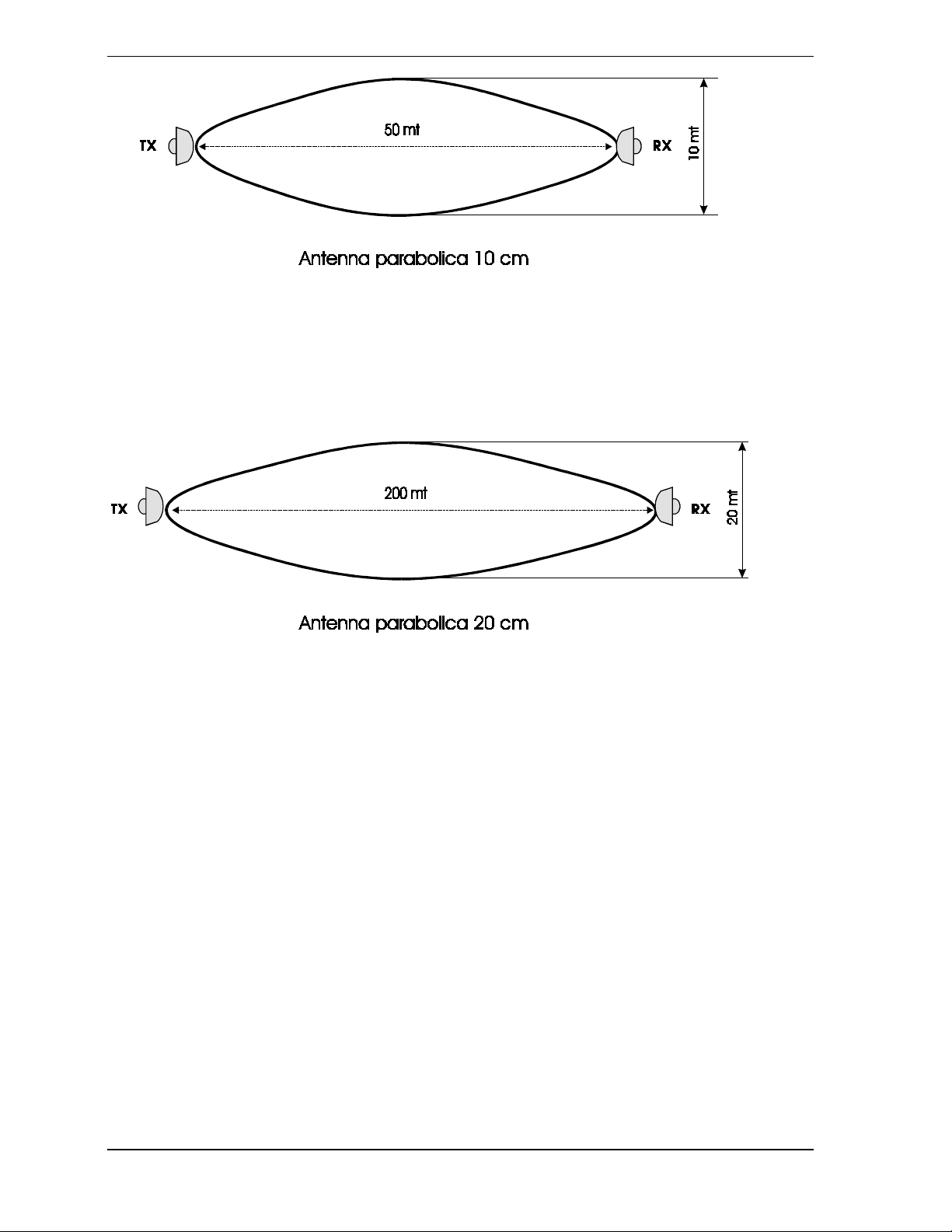
- Two types of antenna are used:
• 10cm PARABOLIC
• 20cm PARABOLIC
The 10cm PARABOLIC antennae are suitable for the formation of rather wide but short range fields of
protection.
The 20cm PARABOLIC antenna forms longer fields of protection, but less wide ranging. (FIG. 1. a-b)
Installation manual ERMO 482
2
ermo482e
CIAS Elettronica version 1.01
Figure 1 a-b - Maximum beam of the sensitive zones
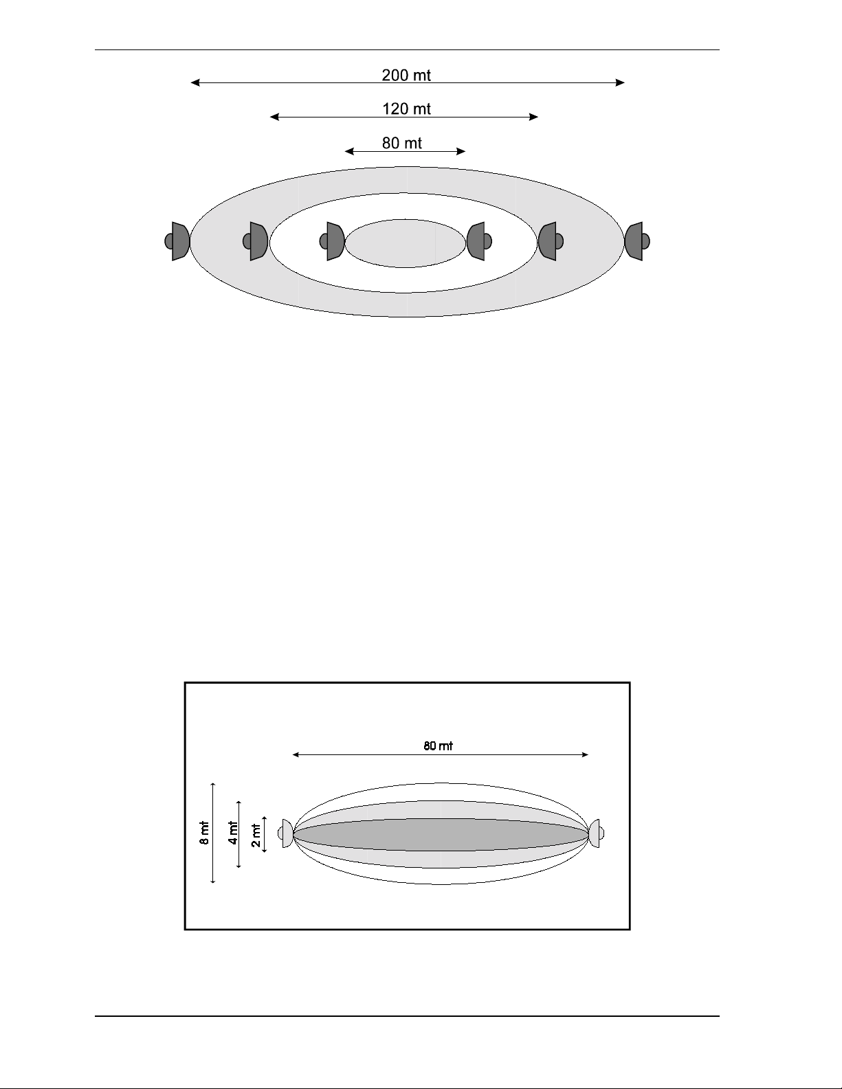
- The effective distance between transmitter and receiver, depending on the type of
antenna, determines the other two dimensions, due to the fact that the opening angle
of the antennae used remains constant to the variation of the reciprocal distance
between transmitter and receiver. (FIG. 2)
Installation manual ERMO 482
3
ermo482e
CIAS Elettronica version 1.01
Figure 2 - Variation of the dimension of the sensitive zone on the variation of the distance
- The level of sensitivity set up on the receiver, according to a particular antenna,
ensures that the microwave barriers can have a sensitivity to more or less intense
disturbance signals. Bear in mind that the weaker signals come from more peripheral
zones of the field, while the more intense signals come from central zones. Thus it is
clear that the regulation of the sensitivity causes a corresponding variation of the
height and breadth of the field of protection. The length, on the other hand, is
determined exclusively by the distance between transmitter and receiver (FIG. 3).
Figure 3 - Variation of the dimension of the sensitive zone on the variation of the sensitivity
Installation manual ERMO 482
4
ermo482e
CIAS Elettronica version 1.01
- The presence of fixed parts, within the sensitive field, alters the dimensions of the
protection field determined, in theory, by the distance between these and the level of
sensitivity imposed on the receiver.
These dimensions are valid only when the barrier is installed in a free space.
In all the other cases the obstacles present will provoke distortions of the shape and
alteration of the size of the protection field.
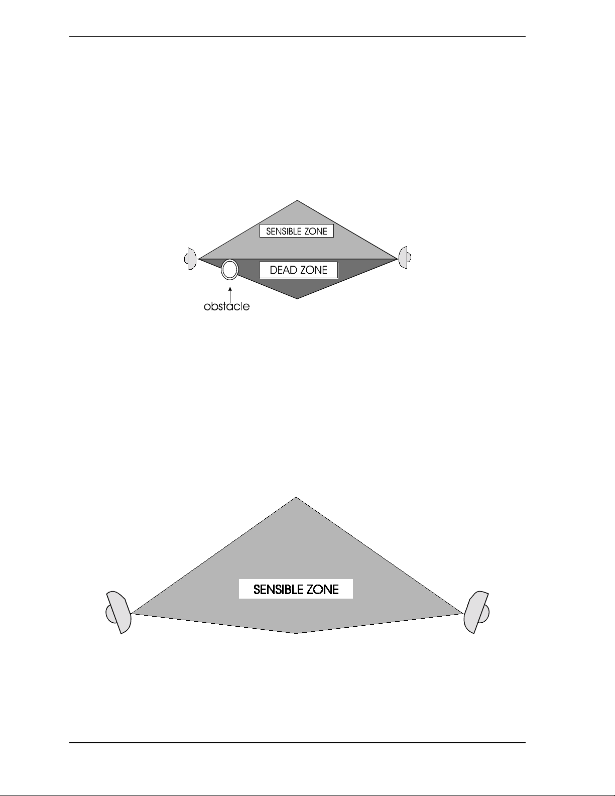
- The nature of the obstacles, eventually present, provokes either a reflection or an
absorption, or a combination of both these phenomena in confrontation with the
electromagnetic energy contained. Therefore, different alterations of the protection
field occur depending on the nature of the obstacles. (FIG. 4)
Figure 4 - Sensitive zone in the presence of an obstacle
- An imperfect alignment between transmitter and receiver causes, a distortion
of the shape of the protective field which is set up, as well as an obvious reduction of
the signal received. This fact becomes clearly apparent when considering that the
protection field is determined, in the first approximation, by the combination of the
principal radiation lobes of the two antennae, which, if perfectly aligned, will establish
a regular and symmetrical protection field in the two halves of the section, if badly
aligned they will cause asymmetry and a more probable interception of obstacles
(even though apparently outside the sensitive field). (FIG. 5)
FIG. 5 - Sensible zone distorsion for bad alignement
Installation manual ERMO 482
5
ermo482e

CIAS Elettronica version 1.01
Bearing these basic considerations in mind, we can state that the general form of the protection field takes the
shape of two trunks of a cone opposed to each other at the base. The minimum dimension of the field is the one
of the antennae, while the maximum dimension is determined by all the other factors already examined.
The breadth of the signal received is the vectorial sum of the direct signal and all the reflected ones. (FIG. 6)
Figure 6 - Vectorial representation of the signal received
It is easy to see how the introduction of any object into the protected field, whether reflecting or absorbing
electromagnetic energy, will provoke an alteration of the preceding condition, causing a variation i n the bread th
of the signal received in proportion to the size of the object introduced and its degree of penetration into the
sensitive field. If the object introduced into the protection field is held in movement, it will provoke a
continuous variation of the breadth of the signal received, thus bringing about a modulating frequency whose
breadth is in proportion to the dimensions and position of the field and of the object introduced, and whose
frequency is proportional to the speed of movement in the field of the object. (FIG. 7)
Installation manual ERMO 482
6
ermo482e
CIAS Elettronica version 1.01
Figure 7 - Representation of the signal received during an intrusion
Electromagnetic energy is radiated from the transmitter in the form of impulses, so that in the presence of an
object in movement within the protection field, as well as the breadth modulation of the peak of the signal
received, we will find a phase modulation of the impulses detected.
As the frequency of the transmitted impulses of electromagnetic energy has 4 different values, it is possible to
carry out on the receiver a check of the correspondence of the frequency received with a sample frequency
within the receiver itself.
Thus, we determine a channeling which, as well as offering greater possibilities to elaborate the signal, makes
the system much less vulnerable with regard to any attempt to neutralise it.
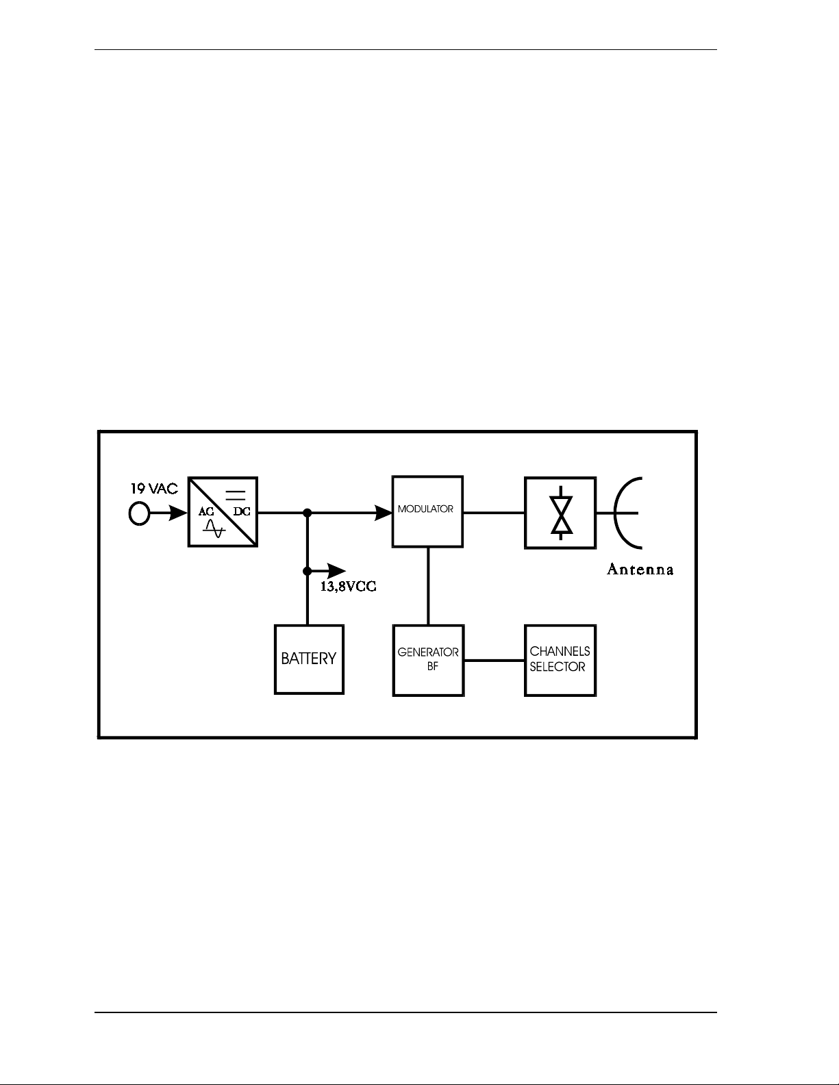
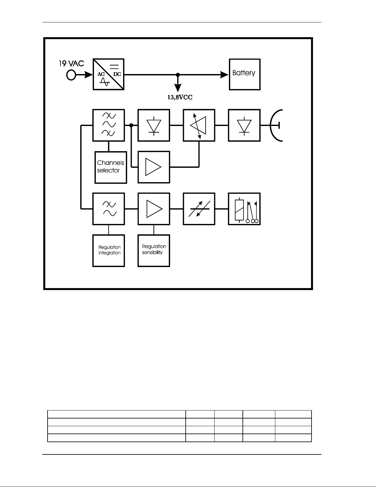
2) BLOCK DIAGRAM
The block diagram of the transmitter of ERMO 482/... is shown in Fig. 8.
Figure 8 - Block diagram of the transmitter
The block diagram of the receiver of ERMO 482/... is shown in Fig. 9 .
Installation manual ERMO 482
7
ermo482e
CIAS Elettronica version 1.01
Figure 9 - Block diagram of the receiver
3) TECHNICAL SPECIFICATIONS
Table 1 shows the technical specifications of ERMO 482/...
Min Nom Max Note
Working frequence 9,5 GHz 9,9 GHz 9,95 GHz
Maximum f o rce - 20 mW -
Modulation - - - on/off
Installation manual ERMO 482
8
ermo482e

CIAS Elettronica version 1.01
Duty-cycle - 50/50 -
Number channels - - 4
Range:
ERMO 482/50 50 m - ERMO 482/80 80 m - -
ERMO 482/120 120 m - -
ERMO 482/200 200 m - Power supply tension ( ): 17 V 19 V 21 V
Power supply tension ( ): 11,5 V 13,8 V 16 V
Power supply current TX ( ): - 155 mA 165 mA
Power supply current RX in control ( ): - 210 mA 220 mA
Power supply current RX in alarm ( ): - 130 mA 130 mA
Power supply current TX ( ): - 33 mA 40 mA
Power supply current RX in control ( ): - 65 mA 72 mA
Power supply current RX in alarm ( ): - 20 mA 25 mA
Room for battery: - - - 12Y/1,9Ah
Alarm outputs:
Contact redome removal (TX) - - 30 VA C-NC
Contact redome removal (RX) - - 30 VA C-NC
Exchange intrusion alarm - - 30 VA C-NC-NA
lighting signals: - -
Presence green led net (TX) - - - ON
Presence green led net (RX) - - - ON
Recognition green led net - - - ON
State of green led NON alarm - - - ON
Sensibility regulation - - - trimmer
Integration regulation - - - trimmer
Weight without battery (TX) - 2910 g Weight without battery (RX) - 2970 g -
Dimensions
Diameter - - 305 mm
Depth jaws included - - 280 mm
Working temperature -25 °C - +55 °C
Performance level: 3°
Level of wrapper protection: IP55
Table 1 - Technical specifications
Additive note for barriers ERMO 482 power supply and earthing:
- The cable which carries the transformer power supply to the apparatus must be
masked and the mask must be connected to the soul
- the metallic case must be connected to the soul, through a suitable earth
terminal projected inside.
4) COMPONENT PARTS OF THE SYSTEM
The ERMO 482/... package is made up of the following parts:
A) Transmitter
B) Receiver
C) Post clamps
D) Cavoflex ends
E) Testing sheet diagrams
F) Instruction manual
Installation manual ERMO 482
9
ermo482e
CIAS Elettronica version 1.01
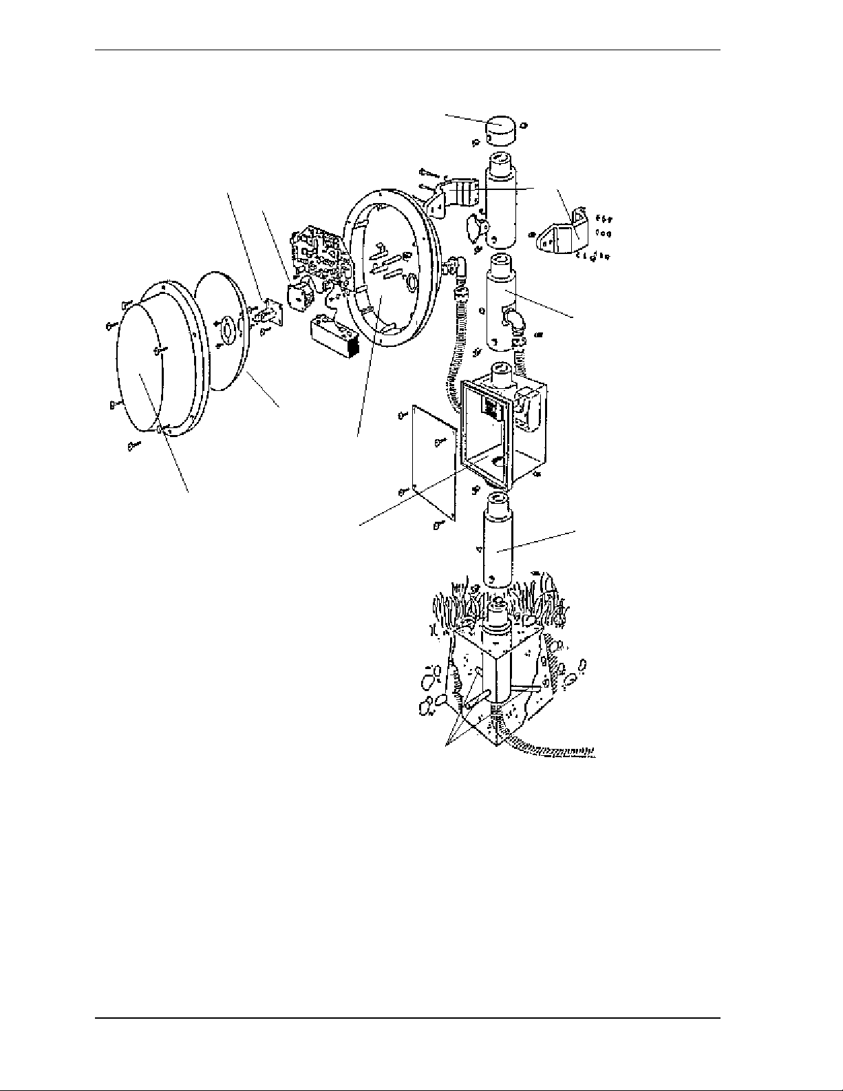
For ease of assembly, the dismantling and the eventual replacement, for assistance, with the various parts of the
apparatus ERMO 482, there is an “exploded” illustration of a barrier head.
Pole
covering
Post
Illuminator
Rx or Tx Cavity
Parabola
Clamps
Pipe with
hole for
cables
Back Cover
Front Cover
Junction box for
transformer
Radials trunk s
5) ACCESSORIES
In the picture of page 10 there are several parts of the accessories that can be supplied on request by quoting the
relevant code number. Here we are:
Trunk Pi pe
A) 15cm trunk pipes
B) Pole covering
C) Junction box
D) Transformers
6) INSTALLATION
Installation manual ERMO 482
10
ermo482e

CIAS Elettronica version 1.01
When designing a volumetric barrier protection system, it is first necessary to carry out an inspection of t he site
to be protected, in order to note the real operating conditions. In fact it is necessary to determine:
6. 1) Number of lines to install
6. 2) Length of each line
6. 3) Land conditions
6. 4) Nature of the ground
6. 5) Presence of walls, fences, posts, trees, hedges, other obstacles
6. 6) Breadth of sensitive bands
6. 7) Breadth of the dead zones near the apparatus
6. 8) Height of the apparatus from the ground
6. 9) Supporting poles, their ground fixtures, connector boxes
6. 10) Connections to AC supply
6. 11) Connection of the battery to reserve supply
6. 12) Connections to the elaboration centre
6. 1) Number of lines to install
As the volumetric barrier protection has to be designed within a closed perimeter, as well as the obvious
considerations of the subdivision of the perimeter into a certain number of lines which take into consideration
the operating requirements within the system, we must remember that it is always best to install a n even number
of lines.
This is due to the fact that the possible reciprocal interferences between adjacent lines are cancelled out if two
apparatus with the same name are installed at the vertices of
the polygon obtained by the installation of the various lines: either two transmitters or two receivers.
Obviousl y, this can always only takes place when there is an even number of lines.
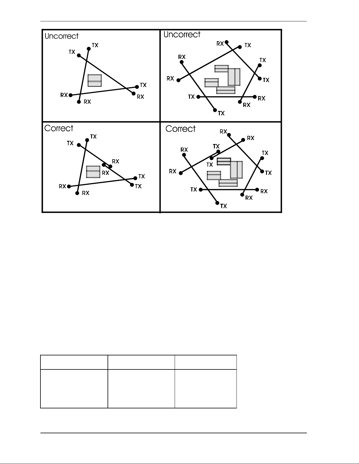
If it is not possible to install an even number of lines, careful considerations should be given to the possible
interferences for the correct choice of the most suitable vertex for the positioning of the transmitter near the
receiver.
The following illustrations show a number of typical cases, with the most appropriate solution. (FIG. 11)
Installation manual ERMO 482
11
ermo482e
CIAS Elettronica version 1.01
Figure 11 - Examples of correct solutions
6. 2) Length of each line
The identification of the length of each line makes it possible to purcha se the appropriate equipment and CIAS
supplies, in the same container, a range of four different capacities and dimensions of the sensitive field.
To better understand this subdivision, there follows a table illustrating the various models, sho wing the capacity
and the type of antenna used. (TAB. 2)
PARABOLA 10 cm PARABOLA 20 cm
ERMO 482 / 50 50 ERMO 482 / 80 - 80
ERMO 482 / 120 - 120
ERMO 482 / 200 - 200
Installation manual ERMO 482
12
ermo482e
CIAS Elettronica version 1.01
Table 2 - Capacity and antenna used for each model
6. 3) Land conditions
The soil is an enormous obstacle along the entire line, thus ables to exert a notable influence on the form o f
intrusion and the response to it.
To avoid shaded and hypersensitive zones, as much as possible, particular attention should be paid to the
conditions of the land.
It should be:
a) Fixed
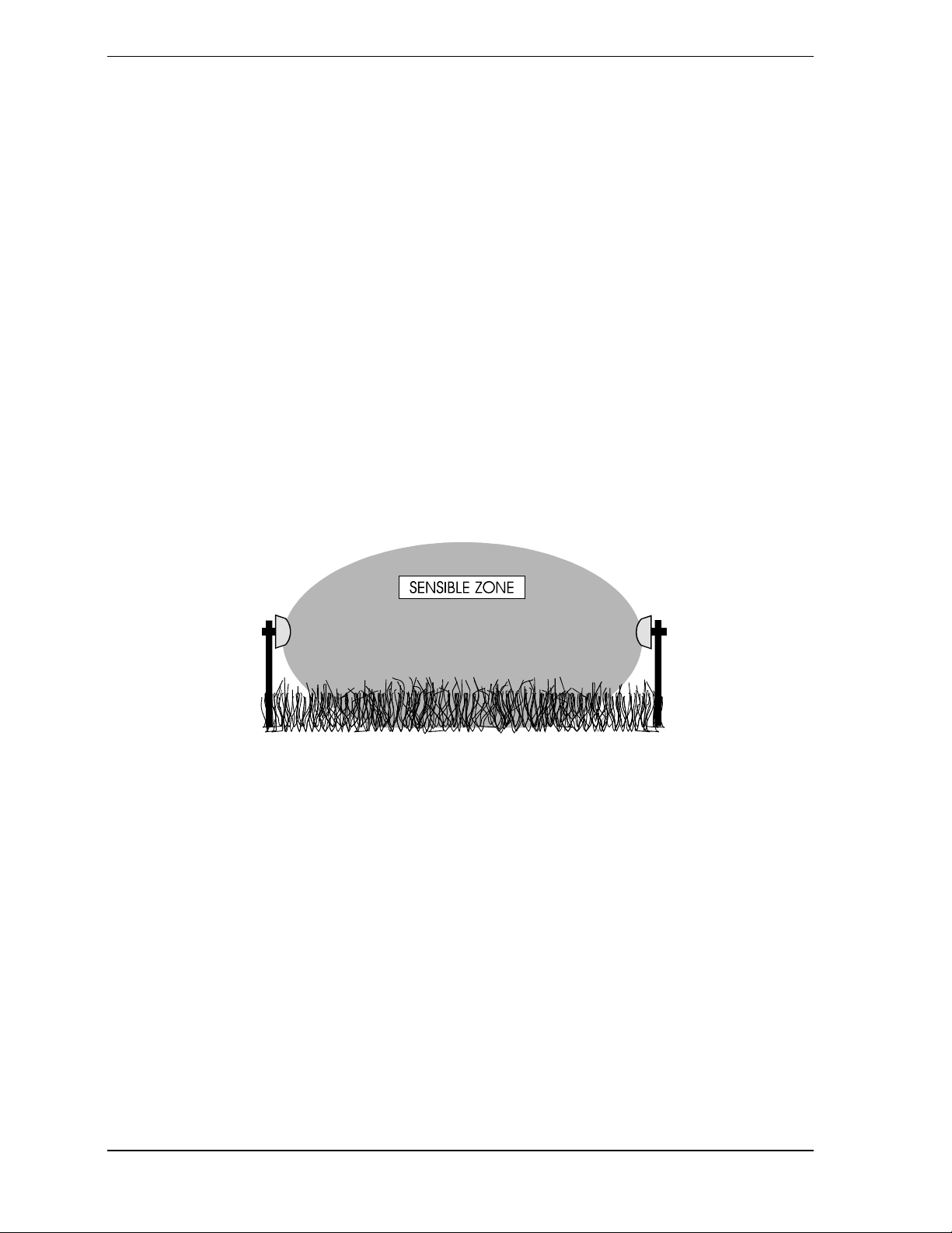
We advise not to install the apparatus where there are vehicle weighbridges, long grass (over 10 cm), ponds,
streams and rivers, and all types of soul where conditions can change rapidly.
If this situation is not taken into consideration, there is the risk that the po sition o f t he soil could c hange rap idl y,
provoking false alarms. (FIG. 12)
Figure 12 - Interference in the sensible zone of high grass
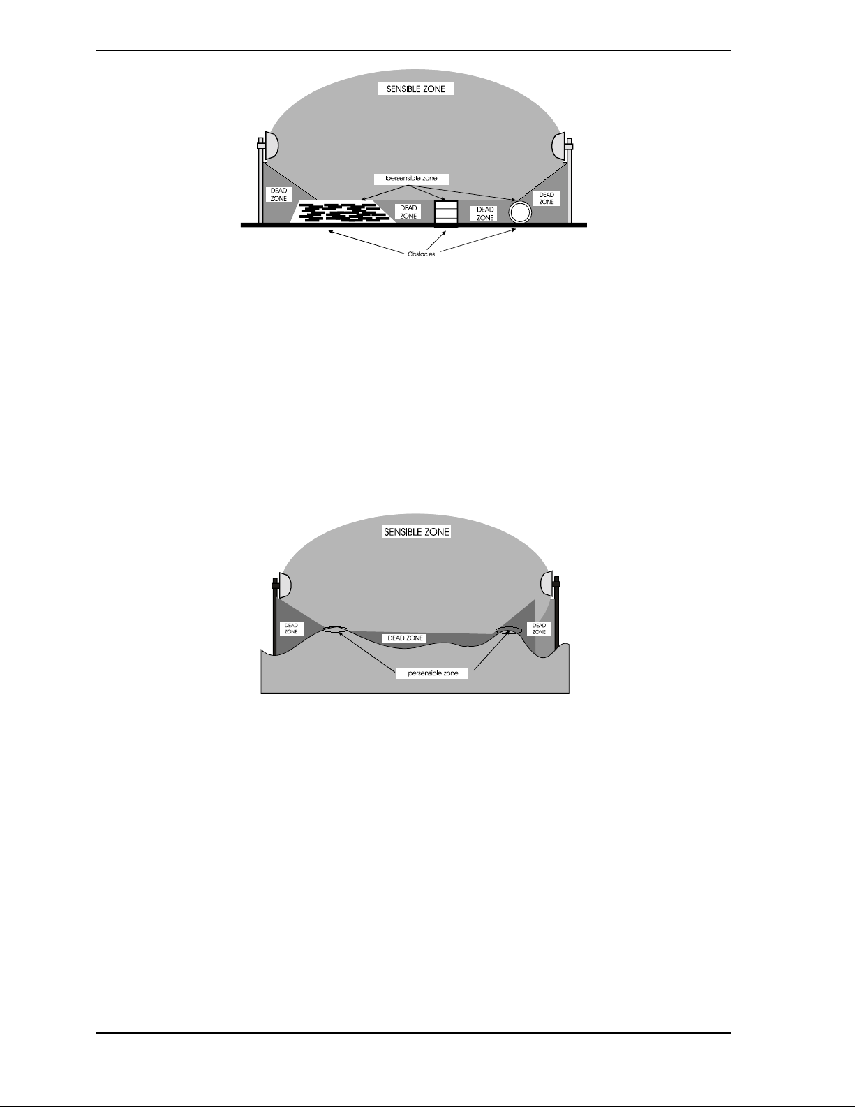
b) Stable
We advise not to install the apparatus where the soil can alter, in the course of the time, because of natural
causes, such as sandy areas, or for man-made reasons, such as material deposits, where it is possible that the
protection zone changes its standard conditions after the installation. If this is not taken into consideration, the
alteration of the soil can lead to the creation of dead and hypersensitive zones with, in the first case, insensitive
areas and, in the latter, false alarms. (FIG. 13)
Installation manual ERMO 482
13
ermo482e
CIAS Elettronica version 1.01
Figure 13 - Formation of dead and hypersensitive zones due to the presence of various obstacles
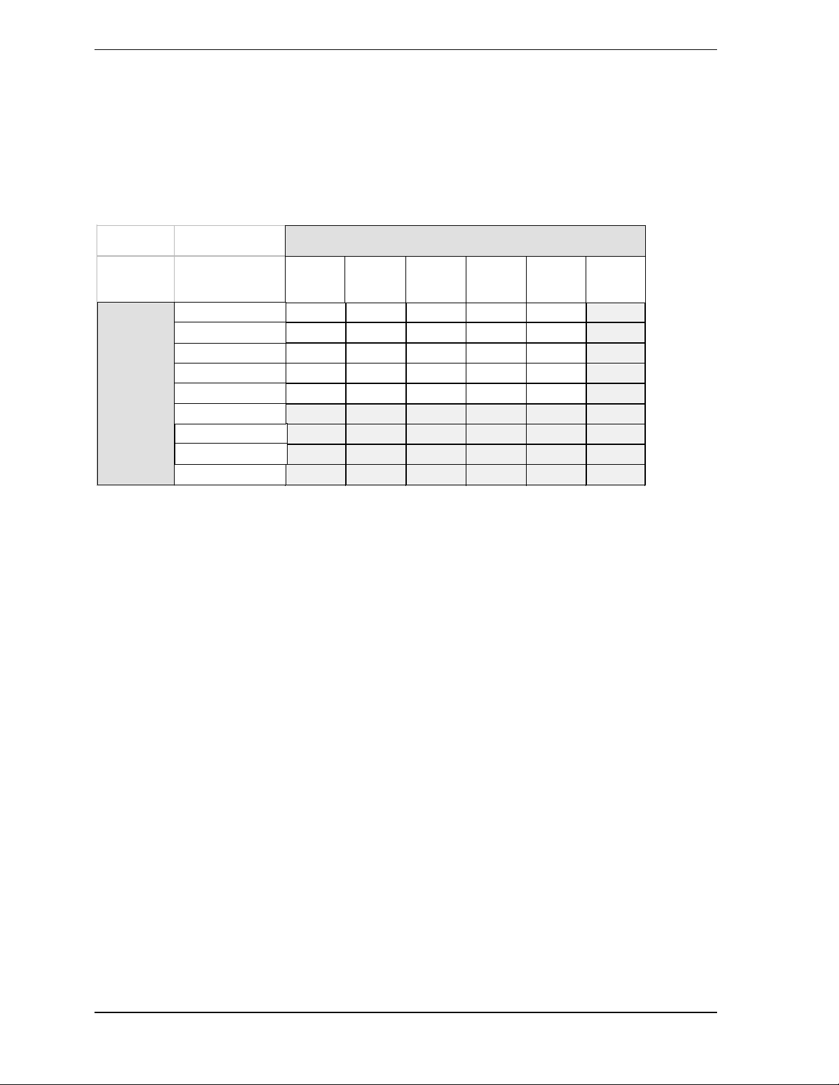
c) Smooth
Be sure that the installation takes place along lines with ondulation of less than ± 20 cm. If the soil is not
perfectly flat, we must bear in mind that there will be zones of less sensitivity or even dead zones in the
depressions, while on the ridges we will find greater sensitivity or even hypersensitivity, with the result, once
again, of possible insensitive areas or false alarms. (FIG. 14)
Figure 14 - Formation of dead and hypersensitive zones due to excessively ondulation ground
6. 4) Nature of the soil
Bearing tha above in mind, there follows a list of the various types of terrain suitable for the installation of the
apparatus:
a) asphalt
b) concrete
c) beaten earth
d) gravel
e) lawn (with grass no higher than 10 cm)
Installation manual ERMO 482
14
ermo482e
CIAS Elettronica version 1.01
The following table summarises the possibility of carrying out a good installation on various possible soils, also
bearing in mind their conditions. (TAB. 3)
LAND COND ITIONS
TYPE
OF
TERRAIN
ASPHALT
CEMENT
GROUN D
GRAVEL
GRASS
METAL
WATER
SAND
VEGETATION
SMOOTH FIXED STABLE INCLINED
SI SI SI SI SI NO
SI SI SI SI SI NO
SI SI SI SI SI NO
SI SI SI SI SI NO
SI SI SI SI SI NO
NO NO NO NO NO NO
NO NO NO NO NO NO
NO NO NO NO NO NO
NO NO NO NO NO NO
WAVY
<20cm
WAVY
>20cm
Table 3 - Use of barriers in relation to the soil
6. 5) Presence of walls, fences, posts, trees, hedges and various obstacles
As we have already mentioned in the general description, any obstacle within the protection field brings about a
distortion of the shape and the alteration of the dimensions.
It should be borne in mind that the obstacles in proximity of the protection field can also cause distortions of the
field itself and, in addition, when these elements are movable, there is the possibility of false alarms.
In general walls, positioned longitudinally to the line, do not cause great problems, as they are fixed and poor
reflectors. But if they are partially transverse or project significantly into the protection field, bear in mind that
dead zones will be created behind them and the signal received could be insufficient to guarantee reliable
operation with regard to false alarms. (FIG. 15)
Installation manual ERMO 482
15
ermo482e

CIAS Elettronica version 1.01
Figure 15 - Formation of dead zone due to the projection of a wall into the sensitive zone
Fences, as they are generally made of metal and therefore highly reflective, can provoke different problems.
First of all, we should be sure that the fence is well fixed, so that i t does not move in the wind. In case of
longitudinal fences, this type of movement could create troubles of high order.
If the fence in question is transverse, it is absolutely essential that it is perfectly immobile. It should be
composed of mesh or bars with a maximum space of 3 cm from one to the other; on the contrary, we could
have false alarms.
Metal fences behind the apparatus can also provoke distortions in the sensitive band, especially if the mesh is
fine (less than 3 cm), and they can cause sudden movement with the possibility of false alarms (FIG. 16).
Installation manual ERMO 482
16
ermo482e

CIAS Elettronica version 1.01
Figure 16 - Possible interference due to the presence of metal fence post
Along the line of the protection field, the presence of tubes, posts or similar is tolerated (lighting standa rds, for
example), provided that their dimensions are not excessive in proportion to the band of protection.
In such a case a sizeable dead zone would be created and if this zone was very large in relation to the band of
protection, the operation would be unreliable, with the possibility of false alarms. (FIG. 17)
Figure 17 - Example of unreliable working caused by the presence of an excessively large obstacle
Trees, hedges and bushes in general require very careful attention, both near and within tha bands of
protection.
These obstacles are variable in dimension and position, and in fact they can b e affected by growth and wind
movement.
We, therefore, advise very strongly not to place the protection bands in proximity of these obstacles. They are
tolerable only if thei growth is limited by methodical maintenance and their movement is checked by suitable
containment barriers. (Fig. 18) Various obstacles may be present along the protection lines, and in the case it is
necessary to take the same precautions as in the previous cases.
Installation manual ERMO 482
17
ermo482e

CIAS Elettronica version 1.01
Figure 18 - Interference of shrubs and branches of trees in the sensitive zone
6. 6) Breadth of the sensitive beam
As we have already seen, the breadth of the sensitive bands depends on the type of antenna used, the distance
between transmitter and receiver and on the sensitivity regulation.The following pictures supply the diameter at
the halfway poi nt of the sens itive ba nds, depe nding on the length, fo r both maxi mum and minimum sen sitivity
of the various models. (fig. 19/20)
Figure 19 - Diameter of the sensitive zone at the halfway point depending on the length of the line for ERMO
482/50
Installation manual ERMO 482
18
ermo482e

CIAS Elettronica version 1.01
Figure 20 - Diameter of the sensitive zone at the halfway point depending on the length of the line for ERMO
482/80 - 120 - 200
6. 7) Length of the dead zones in proximity of the apparatus
The length of the dead zones in proximity of the apparatus depends on the distance of the apparatus from the
ground, the sensitivity set up on the receiver and the type of antenna used.
6. 8) Height of the apparatus from the ground
Bearing in mind the previous considerations and on the arrangement of the system, it is necessary to install the
apparatus at the right height from the ground.
In average conditions of the system and of taring the height should be 85 cm. (The measurement is calculated
from the ground to the centre of the apparatus). The following pictures give a complete idea of the situation for
the two types of antenna used. (FIG. 21-22)
Installation manual ERMO 482
19
ermo482e

CIAS Elettronica version 1.01
Figure 21 - Le ngth of the dead z one near the appar atus depending on t he height from the ground for ERM O
482/50
Installation manual ERMO 482
20
ermo482e

CIAS Elettronica version 1.01
Figure 22 - Length of the dead zone near the apparatus depending on the height from the ground for ERMO
482/80 - 120 - 200
The following illustrations show the dead zones near the intersection of the two lines. (FIG. 22a - 22b)
Installation manual ERMO 482
21
ermo482e

CIAS Elettronica version 1.01
Figure 22a - Overlapping of two sensitive bands in an intersection
Figure 22b - Overlapping of two sensitive bands in an intersection
6. 9) Supporting poles, ground fixtures, Junction boxes
The following illustration shows the maximum dimensions of each ERMO 482/... head and its support post.
(FIG. 23)
The external diameter of the support posts should be 60 mm. Poles of this diameter are
Installation manual ERMO 482
22
ermo482e

CIAS Elettronica version 1.01
Figure 23
easy to find as they correspond to the external dimensions of two inch gas common pipes.
As already seen in the section on accessories, CIAS is able to supply aluminium trunking pipes in 15 cm length,
which can be used to build poles of the desired length, as well as available covers for poles.
The best solution is shown in picture at pag. 10.
The poles can be fixed to the ground by inserting them into holes which are then filled with concrete.
The junction boxes contain the AC supply transformer, with the overall dimensions of: 85 * 70 * 70 mm.
For corrent AC supply, this transformer should be placed immediately near the head it supplies. Picture 10
shows an excellent solution using a coaxial aluminium junction box at the pole made of trunkings. This
junction box (supplied by CIAS as an
accessory) can house a bipolar switch and a 12V-5,7 Ah battery as well as the transformer.
Note: The cable which carries the barrier supply from the transformers to the battery heads must be masked, and
the mask must be connected to the ground.
6. 10) Connections of the apparatus t o the AC supply
The apparatus work with AC supply at a maximum voltage of 20 V. eff. The connection between head and
transformer should be inferior to 1.5 mmq.
The conductors which connect the transformer to the 220 Vcc must have a section of 2.5 mmq.
If the AC current is low tension (20 V eff.), insulation transformers should be used, 20 V: 20 V of at least 80
VA. (fig. 24)
Installation manual ERMO 482
23
ermo482e

CIAS Elettronica version 1.01
Figure 24 - Two correct ways to supply the apparatus
Connection between apparatus and transformer is similar to the previous one, the connection to the 20 V grid
should be carried out by bearing in mind its length and the possibility that each sin gle head of the apparatus ma y
require a maximum current of 1A. In any case, the section should be no less than 1.5 mmq.
6. 11) Connection of the battery for reserve supply
Within each head of the apparatus, there is a space for the housing of a rechargeable lead battery of 12 Vcc - 1,9
Ah. The battery is charged by the supplier inside each head and it is connected to it by a red and black plate with
connecting clip fitted within each single head.
This battery, when there is no grid power, gives apparatus autonomy of over 12 hours.
if greater autonomy is necessary, a reserve supply group should be installed in the immediate vicinity of each
head.
The connection of these groups is carried out at the terminals of the apparatus marked with the symbols of mass
and + 13,8 Vcc.
The size of these groups should bear in mind that the DC absorption of each single head is 70 mA approx.
6. 12) Connection of the apparatus to the co ntrol panel
Installation manual ERMO 482
24
ermo482e

CIAS Elettronica version 1.01
The transmitter head consists of a normally closed contact free from potentials, for protection during the
container o pening.
The connections of these outputs to the elaboration centre should be made with screend cable with asection of
no less than 0.5 mmq. Because of long cables circuits in external environment, troubles can be induced on the
cables themselves and so they can be conduced to the elaboration control panel These troubles can overtake, in
case we use balanced lines, very high values, able to provoke false alarms. Therefore we advise not to use
balanced lines.
If it is necessary to protect the alarm line from cutting and short-circuit we advise to adopt the following table
(FIG. 25).
Figure 25 - Protection of the line from cuts and short circuit by uncoupling relay; this connection is particularly
immune from disturbances that can be picked up by the line
Installation manual ERMO 482
25
ermo482e

CIAS Elettronica version 1.01
STC 95 INSTRUMENT
Figure - 26 -
1. 3M connector 13. Buzzer threshold increase
2. LCD display 14. Buzzer threshold decrease
3. LED display 15. Buzzer enable/disable
4. 13.8VDC supply LED 16. Buzzer on LED
5. detected field LED 17. Loop open/close
6. TX/RX sens. meas. LED 18. Loop open LED
7. Rag meas. LED 19. Measurement on/off
(Medusa PLUS TX/RX
Version)
8. 9 VDC supply LED 20. Module measurements
on/off
(Medusa PLUS TX/RX
Version)
Installation manual ERMO 482
26
ermo482e

CIAS Elettronica version 1.01
9. 5 VDC supply LED 21. TX/RX measurements
on/off
(ermo 482-583-medusa base-
medusa)
10. Measurement selection 22. TX/RX me asurements on
LED
11. Manual gain increase (ermo 482-583-medusa base-
medusa)
12. Manual gain decrease 23. RCA connector
CONNECTING STC 95 TO CIAS BARRIERS
Installation manual ERMO 482
27
ermo482e

CIAS Elettronica version 1.01
Figure - 27 -
7. ALIGNMENT AND CALIBRATION
Installation manual ERMO 482
28
ermo482e

CIAS Elettronica version 1.01
The STC 95 was developed by CIAS for aligning and calibrating its intruder
sensor barriers, making it an ideal tool for installers.
The unit is shown in figure 26 on page 28, together with its function
specifications. Figure 27 shows the interconnections between the STC 95 and
CIAS barriers.
To set up and test E RMO 482 barriers, p r oceed as follows:
7.1 - go to the transmitter
- remove the radome unscrewing the allen screws
- connect the AC power supply (19 VA C) to terminals 7-8 (fig. 28)
- check that the "MAINS" led lights (fig. 28)
- connect the faston connectors to the battery, observing the correct
polarity (red wire to battery positive, black wire to battery negative)
WARNING: if polarity is acci dentally inverted, the transmitter circuit fuse will
blow (fig. 28) If th e connections are then corrected and the blown
fuse (2A) replaced, the transmitter will op erate normally.
- set one of the 4 available frequencies ( F1, F2, F3, F4 ) by switching
ON the correspondin g dip-switch (the others must all be OFF) (fig. 28)
- check that the transmitter operates using the STC 95 (fig. 26).
7.1.1 - connect the STC 95 to the ERMO 482 barrier as shown in f ig. 27.
- plug the 4-pin connector (fig.28) into the "MEASUREMENT
CONNECTOR" on the TRANSMITTER CIRCUIT" and proceed as
follows:
7.1.2 - check that led 22 (fig. 26) ligh ts. If n ot, pres s butt on 21 (fig. 26 ) to turn it
on
7.1.3 - press button 10 (fig. 26) as many times as are necessary to make led 4
light up (fig. 26). The voltage displayed must be 13.8 VDC +/- 10%
7.1.4 - press button 10 until led 8 lights up. Voltage displayed (2) must be
9VDC+/-10%.
7.1.5 - press button 10 until led 6 lights up. Voltage displayed (2) must be 5
VDC +/- 10%.
Installation manual ERMO 482
29
ermo482e

CIAS Elettronica version 1.01
AA: BULB FOR ANTIREMOVAL. IT MUST BE ALWAYS TURNED
UPSTAIRS. THE HEAD REMOVAL PROVOKES ALARM FOR
SABOTAGE.
AA: BULB FOR ANTIREMOVAL. IT MUST BE ALWAYS TURNED
UPSTAIRS. THE HEAD REMOVAL PROVOKES ALARM FOR
SABOTAGE.
Installation manual ERMO 482
30
ermo482e

CIAS Elettronica version 1.01
7.2 - go to the receiver:
- remove the radome unscrewing the allen screws
- connect the AC power supply (19 VA C) to terminals 7-8 (fig. 29)
- check that the "MAINS" led lights
- connect the faston connectors to the battery, observing the correct
polarity (red wire to battery positive, black wire to battery
negative)
WARNING: if polarity is accidentally inverted, the receiver circuit fuse will
blow (fig. 29) If the connections are then corrected and the blown fuse (2A)
replaced, the receiver will operate normally.
- set one of the 4 available fre quencies (F1, F2, F3, F4) by switc hing
ON the corresponding dip-switch (th e others must all be OFF) (fig.
29)
- check that the receiver operates using the STC 95 (fig. 26).
7.2.1 - connect the STC 95 to the ERMO 482 barrier as shown in f ig. 27.
7.2.2 - check that led 22 (fig. 26) lights. If not, press button 21 (fig. 26) to turn
it on. Plug the 7- pin connector into "MEASUREMENT CONNECTOR"
socket on the receiver circuit b oard (fig. 29) and proceed as follow s:
7.2.3 - press button 10 (fig. 26) as many times as are necessary to make led 4
light up (fig. 26).
The voltage displayed must be 13.8 VDC +/- 10%.
Installation manual ERMO 482
31
ermo482e

CIAS Elettronica version 1.01
If the units have already been aligned by eye, check that the leds "CHA"
and "ALA" light up, indicating channel recognition and non-alarm status (fig.
29).
To optimise connection, proceed with electronic tune-up as follows:
7.2.4 - Check that led 16 is off. If it is lit, press button 15 to turn it off. This
disables the STC 95 interna l buzzer (fig. 26).
7.2.5 - Check that led 18 is lit. If it is off, press button 17 to turn it on. This
opens the LOOP
(fig. 26).
7.2.6 - press button 10 until led 5 lights up. Voltage displayed (2) must be 6
VDC +/- 10%, and the central led (3) in the led array must be on (fig. 26). If the
displayed voltage is different and one of the leds near the end of the array is lit,
press button 11 or 12 until these conditions are corrected (centre led lit and
6VDC display e d).
7.2.7 - After sl ackening the screws holding the receiver to the pole, rot ate the
receiver in the horizontal plane until the maximum reading is obtained on the
display (2). The led array will light from the centre led towards the right. If the
last led on the right stays on, press button 12 until the centre led lights, and
continue adjusting the receiver head in the horizontal plane until the maximum
reading is obtained on the dis p lay (2).
7.2.8 - Repeat the tuning operation with the transmitter head horizontal
adjustment.
7.2.9 - Once optimal tuning is obtained, lock horizontal movement of the two
heads (RX and TX).
7.2.10 - Slacken the vertical adjustment lock on the receiver (RX) head, and
Installation manual ERMO 482
32
ermo482e

CIAS Elettronica version 1.01
point it upwards. Shift it slowly downwards until the maximum reading is
obtained on the display (2) and the led array (3) in the same way as for
horizontal adjustment.
7.2.11 - Repeat the vertical adjustment on the TX head. Once optimal readings
are obtained, lock t he vertical movement on both heads (T X and RX).
7.2.12 - Press button 17 and check that led 18 goes off. Check that after a
maximum recovery time of two minutes, the value shown on the display (2)
reaches 6 VDC, and that the centre led in the array lights.
7.2.13 - Press button 10 until led 7 lights up; check that display shows voltage
of between 2.5 and 6.5 VDC. This RAG value is directly proportional to the
distance between transmitter and receiver heads. Press button 10 until leds (6)
light.
7.2.14 - Adjust "SEN" trimmer on receiver head (fig. 29) until displayed value
lies between 0 and 9 VDC. 0V corresponds to maximum and 9V to minimum
sensitivity.
7.2.15 - Adjust "INT" trimmer, next to "SEN" trimmer (fig. 29), until the
desired integration level is obtained.
7.2.16 - Press button 15 until led 16 lights. This indicates that the buzzer is
enabled (fig. 26).
Make sure that the buzzer remains silen t during th e abs ence of movement
in the protected
field. If the buzzer sounds, press button 14 until it is mute.
If the buzzer is already mute when this function is switched on, press
button 13 until the
Installation manual ERMO 482
33
ermo482e

CIAS Elettronica version 1.01
buzzer sounds intermittently, then press button slightly until it is mute
again.
7.2.17 - Run the barrier crossing tests, checking first the intermittent buzzer
alarm and then the continuous buzzing indicating that the barrier has been
crossed.
Check that the buzzer do es not sound when there is no movement in the
field. If this
occurs, even int e rmittently, the field is distu rbed.
If the barrier is crossed by very large targets, the CHANNEL LED (fi g.
29) may also go out. This indicates that the RF signal has been interrupted.
Barrier set up must suit specific user requirements. However, it should be
borne in mind that excessive sensitivity will tend to cause the alarm to go off
under not strictly alarm conditions. Each individual case will require a
compromise in parameters. Furthermore, it should be remembered that the
sensor's perception of barrier crossing speed is affected by the integration
adjustment, while the perception of the mass crossing the barrier is affect ed by
the sensitivity adjustment.
7.2.18 - The STC 95 features an RCA socket (23) (fig. 26). This can be
connected via a suitable cable to an oscilloscope (any type currently on the
market), for analysis of the received signal wave-form. The wave-form should
be of the type shown in figure 30 if the transmitter and receiver heads are
properly aligned.
Poor alignment will lead to a received s ignal wave-form like that in figure
31, where noise can be seen at the tips of the square wave. This means that the
received signal is not of good quality. In this case, the alignment tuning
operations should be repeated until the wave-form is like that in figure 30.
Installation manual ERMO 482
34
ermo482e

CIAS Elettronica version 1.01
All data on the measurements taken on th e installation should be written
in the test cards provided with each barrier. This will make any assistance
operations much easier.
7.2.19 - Refit the radomes to the receiver and transmitter heads. Tighten down
the mounting screws to ensure water-tightness.
A bad connection produces a waveform like the one shown in fig. 31.
Note the presence of noise on the cusps of the square wave. This means that the
signal received is not good. In this case repeat the aiming operations until th e
waveform in figure 30 is achieved.
All data relating to measurements carried out on the system should be
written on the test cards which are supplied with every barrier. This will make
assistance operations extremely easy.
Replace the radomes and fix them evenly with the appropriate screws in
order to achieve good water-tightness.
8. MAINTENANCE
When breakdowns occur at a barrier, it is necessary to proceed as follows:
8.1 - Go to the receiver and, after removing the radome, plug in the connecto r
of instrument STC 95 as described in points 7. 2.1/7.2.2.
8.2 - Check that the "CAN" and "ALL" leds (fig. 29) are lit; obviously this
check must be carried out with no moving obstacles in the protection field.
8.3 - Press key F10 on the STC 95 in order to light led 4 (fig. 26).
Check that the 13.8 DC voltage is within æ10%.
Installation manual ERMO 482
35
ermo482e

CIAS Elettronica version 1.01
If the voltage is lower, it means the power supply unit is not operating
correctly, or the AC power supply is missing; the latter possibility is also shown
by the "GRID" led going out (fig. 29). In th is case, check that there is a volt age
across the primary winding of th e transformer (220 V) and its efficien cy.
In connection with th is , it should be remembered that if th e t r an s former i s
not closed inside a sealed case, water may corrode the connections, and these
may consequently disconnect and possibly cause irreversible damage to the
transformer.
In this case, replace the transformer and make sure its container is
hermetically sealed.If, on the other hand, the readings are higher, it means that
the power supply unit is faulty, or that the installer has adjusted the voltage
regulation trimmer.
Check the voltage calibration by proceeding as follows:
Disconnect the battery fastons and connect them to the prods of a
precision electronic voltmeter set to the 20 V DC scale. If the reading is not 13.8
V DC adjust the RT trimmer until the reading reaches 13.8 V DC.
If it is not possible to set the voltage to that value, it means the regulator
is unrepairable.
In this case, it is necessary to replace the printed circuit. If the problem
can be solved by adjustment, remember to block the trimmer in position with a
drop of fast-dry ing paint.
8.4 - Press key 10 on the STC 95 until led 5 comes on (fig. 26).
Check that the voltage read in the "FIELD" RX function is 6 V DC
æ10%.
When there are no moving objects in the protection field, this reading is
very stable.
Installation manual ERMO 482
36
ermo482e

CIAS Elettronica version 1.01
Any oscillations greater than æ500 mA show system instability which
may either mean interference due to moving objects in the protection field or
barrier malfunction.
Occasional large oscillations (> 1V) may mean transmitter malfunction;
in this case, the tran smitter kit should be replaced.
Small oscillations are almost certainly due to interference in the
protection field (tree foliage, grass waving in the wind, etc.); in this case the
cause of the disturbance should be removed.
If the reading in "FIELD" is different from the one shown (> æ 1V), it
means the receiver has broken down and therefore the RX kit should be
replaced.
8.5 - Press key 10 until led 7 comes on, and check that the voltage reading on
the display is between 2.5 and 6.5 V DC. This RAG value is directly
proportional to the distance between the transm itter and receiver heads.
Check that the RAG has a value of between 2.5 and 6.5 V DC. If the
reading on the display (2) reaches values of greater than 6.5 V DC, it means that
the signal arriving at the receiver is very low, and therefore the connection is
highly precarious.
This fact may be the result of two classes of problems, the first regards
receiver breakdown, and the second regards transmitter breakdown. In order to
find out which event has occurred, it is necessary to carry out measurements on
the transmitter as shown in the n e xt chapter (poi nts 7.1.3/7.1.4/7.1.5).
If, after carrying out measurements on the transmitter, it has been shown
to be operating correctly, the receiver kit should be replaced as shown in the
"USE OF ASSISTANCE KITS AND THEIR FUNCTION" chapter.
It is important to notice that the RAG measurement taken during
Installation manual ERMO 482
37
ermo482e

CIAS Elettronica version 1.01
assistance is not only useful for revealing the breakdown but also shows any
change in the environmental conditions of the protection field.
In fact, if the installer has calibrated the system correctly, filled in the test
cards which accompany each barrier, and written the RAG reading after the
electronic aiming among the data on the card, comparison between the value
shown on the test card and the one read during assistance gives an immediate
indication of the barrier opera tin g state.
More precisely, if the reading du ring assistance is only sl ightly different
from the one shown on the card (æ300 mV DC), the radio-frequency signal
which arrives at the receiver is good and ensures correct barrier operation.
In order to understand the meaning of the RAG measurement better, it is
important to remember that it is strictly connected with the quantity of the radiofrequency signal which arrives at the receiver.
It can therefore easily be understood that a drop in this signal (which is
equivalent to an increase in the RAG value) compromises microwave barrier
operation.
The signal received can be most efficiently checked by observing the
waveform at the receiving head as described in point 7.2.18.
Check that the 13.8 V DC, 9 V DC and 4.5 V DC voltages at the
transmitting head are correct within æ1 V DC. If one of the two or both are
higher or lower, it means that the transmitting head has broken down. Replace
with the TX assistance kit.
9. USE OF THE ASSISTANCE KITS AND THEIR FUNCTION
The assistance kits consist of the processing circuit part and the
Installation manual ERMO 482
38
ermo482e

CIAS Elettronica version 1.01
microwave part; more precisely, the transmitter kit (TX KIT) consists of a
printed circuit and the microwave detector cavity.
One important fact to bear in mind is that the assistance kit is always
calibrated for maximum performance, i.e. 200 metre range.
This is in order to make the task of the pers on called upon to provide the
assistance easier
since it avoids having to have four different kits according to the ranges.
In this way, the
installer no longer has the expense of buying complete barriers for the
assistance, and the
operation is al so made simpler and quicker.
Replacing the circuit and cavity parts both on the transmitter and receiver
does not alter
the orientation of the barrier and therefore it is not necessary to carry out
aiming operations again.
7. ALIGNEMENT AND CALIBRATION MEDUSA BASE
Installation manual ERMO 482
39
ermo482e

CIAS Elettronica version 1.01
In order to make the alignment and the calibration of the barrier MEDUSA
BASE it is necessary to proceed in the following way:
7.1 - Go to the transmitter
- Remove the radome unscrewing the allen screws
- Connect the AC power supply (19 VAC) to the terminals 1 and 3 of J7
(fig. 31)
- Check that the green le d lights for net presence
- Connect the faston to the battery, observing the correct polarity (red wire
to
battery positive, black wire to battery negative)
WARNING
: If polarity is accedentally inverted, the transmitter circuit
fuse F3 (2A) will blow . If the connactions are then corrected
and the blown fuse replaced, the transmitter will operate
normally.
- Verify that the module RF TX is connected to the connector TX1 J1 of the
BASE
SERVER TX (fig. 31).
- Set one of the 4 available frequencies (1/2/3/4) by switching ON the channels
selector on the module RF TX (fig. 31).
- On the module RF TX, the only switched indication is the red led, which
corresponds
to the writing “GUASTO” (fig. 31). The led is switched on in case of nonworking of
the oscillator RF.
- Check that the transmitter operates using th e STC 95.
7.1.1 - Insert the connector of the STC 95 into the connector J6 of the ci rcuit
BASE
SERVER TX (fig. 33) and proceed as follows:
7.1.2 - Verify that the led 22 (fig. 29) is switched on. If it is switched off,
press the
button 21 (fig. 29) to switch it on.
7.1.3 - Press button 10 (fig. 29) as many times as are necessary to make the led
4 light up. The voltage displayed (2) must be 13.8 VDC +/- 10%.
Installation manual ERMO 482
40
ermo482e

CIAS Elettronica version 1.01
7.1.4 - Press the button 10 until led 8 lights up. The voltage displayed (2) must
be 9 VDC +/- 10%.
7.1.5 - Press the button 10 until led 6 lights up. The voltage displayed (2) must
be 5 VDC +/- 10%.
7.2 - Disconnect the instrument STC 95 from the circuit BASE SERVER TX
and go to
the receiver:
- Remove the radome unscrewing the allen screws
- Connect the AC power supply (24 VAC) to the terminals 1 and 3 of J7
(fig. 34)
- Check that the green led is switched on and the red led of intrusion alarm
on the
circuit BASE SERVER RX (fig. 34)
- Connect the fastons to the battery.
WARNING: if polarity is accidentally inverted, either on the transmitter
or on the receiver, we have the interruption of the F3 (2A) fuse on
the circuits base server TX and/or RX. If the connections are
then corrected and the blown fuse replaced, the barrier will
operate normally.
- Check that the module RF RX is conn ected to th e connector RX1 J3 of
the circuit
Base Server RX (fig. 34).
- Consider the same channel on the TX by operating on the channels
selector on the module RF RX (fig. 32).
- On the module RF RX there are two leds with the writing “CHANNEL”
and
“ALARM”. The first one is switched on when the channels
on TX and RX are the same, the second one is switched on when the
barrier is
not in allarm (fig. 32).
- Check the correct working through the ST C 95.
7.2.1 - Insert the connector STC 95 into the “MEASUREMENT
CONNECTOR” J6 of the circuit base server RX (fig. 34) and proc eed as
follows:
Installation manual ERMO 482
41
ermo482e

CIAS Elettronica version 1.01
7.2.2 - Check that leds (22) (fig. 29) is swithed on, if it is sw itched off press
the
button 21 to switch it on (fig. 29).
7.2.3 - Press button (10) to light up led (4 ) (fig. 29). The vol tage on the dis play
(2) must be 13.8 Vdc +/- 10%. If the previous aiming of the apparatus has
been done correctly, we must see on the module RF RX (fig. 32) the lighting
up of the leds “CHANNEL” and “ALARM” which indicate the channel
recognition and the non-allarm indication. In order to optimize the link we
must make the electronic aiming in the following way:
7.2.4 - Check that led (16) is switched off. If it is switched on press button
(17) to switch it on, so that we have the “LOOP” opening (fig. 26).
7.2.5 - Check that led (18) is switched on. If it is s witched off press but to n (17 )
to switch it on, so that we have the “LOOP” opening (fig. 26).
7.2.6 - Press button (10) in order to obtain led (5) lightning.
Check that on the display we can see a tension of about 6 Vdc and on
led (3) bar the central led is switched on. If the value is different and the
switched led is near the limits, press either the button (11) or the button
(12) until we will have the previous condition described (lighting of bar central
led and indications of about 6 Vdc on the display).
7.2.7 - After slackening the screws holding the receiver to the pole, rotate the
module RF RX in the horizontal plane until the maximum reading in
obtained on the display (2).
7.2.8 - Repeat the tuning operation wi th the horizontal regulation of th e module
RF TX.
7.2.9 - Once optimal tuning is obtained, lock the horizontal movement of the
two heads RF TX and RF RX.
7.2.10 - Slacken the vertical adjustement lock on the receiver (RX) head, and
point it upwards.
Installation manual ERMO 482
42
ermo482e

CIAS Elettronica version 1.01
Shift it slowly down wards until the maximum reading is obtained on the
display (2) and led array (3) in the same way as for horizontal
adjustement.
8. ALIGNMENT AND CALIBRATION MEDUSA PLUS
The barrier MEDUSA PLUS is different from the MEDUSA BASE as in the
transmitter and receiver heads there are respectively two modules RF TX and
two modules RF RX.
Also the circuits BASE SERVER TX and BASE SERVER RX are different
from the barrier MEDUSA BASE:
To make the alignement and calibration of the barrier MEDUSA PLUS it is
necessary to proceed as it follows:
8.1 - Go to the transmitter
- Remove the radome and unscrew the allen screws
- Connect the AC (24 V AC) to the terminals 1 and 3 of J7 (fig. 30)
- Check that the green led is switched on
- Connect the fastons to the battery by respecting the polarities (red wire to
battery
positive, black wire to battery negative).
WARNING: the accidental inversion of polarity on the battery, either on
the transmitter or the receiver, provokes the fuse F3 (2A)
interr uption on the circ uits base server TX and/or RX. If t he
connections are then corrected and the blown fuse replaced,
the barrier will work normally.
- Check that the module RF TX 1 is connected to the connector TX1, J1 of the
circuit
BASE SERVER TX PLUS (fig. 34).
Installation manual ERMO 482
43
ermo482e

CIAS Elettronica version 1.01
- Check that the modul e RF TX 2 is connected to the connector TX 2 J2 of the
circuit
BASE SERVER TX PLUS (fig. 34).
- Set one of the 4 available frequencies (1/2/3/4 ) by using the channels selector
on the
module RF TX1.
- Set a different channel among the available ones (1/2/3/4) by using tha
channels
selector on the module RF TX 2.
- On the module RF TX, the only lighting indication is the red led, which
corresponds
to the writing “GUASTO” (fig. 31). The led lights for non-working of the
oscillator
RF.
- Check the correct working of the transmitter through the instrument STC 95.
8.1.1 - Insert the connector of the STC 95 on the connector J6 of the circuit
BASE SERVER TX PLUS (fig. 34) and proceed as follows:
8.1.2 - Check that the led 22 (fig. 29) is switched on. If it is switched off press
the button 21 (fig. 29) to switch it on.
8.1.3 - Press the button (10) until the led (29) as many times as it is necessary to
switch on the led (4). The voltage on the display (2) must be 13.8 Vdc +/-
10%
8.1.4 - Press the button (10) until the led (8 ) is switched on. Th e voltage on the
display (2) must be 9 Vdc +/- 10%.
8.1.5 - Press the button (10) until the led (6 ) is switched on. Th e voltage on the
display (2) must be 5 Vdc +/- 10%.
8.2 - Disconnect the instrument STC 95 from the circuit BASE SERVER TX
PLUS and go to the receiver:
- Remove the radome and unscrew the allen screws
- Connect the AC power supply (24 VAC) to the terminals 1 and 3 of J7
(fig. 35)
Installation manual ERMO 482
44
ermo482e

CIAS Elettronica version 1.01
- Check that the green led lights and the two red leds of intrusion alarm
RX 1 and RX 2 on the circuit BASE SERVER RX PLUS (fig. 35).
- Connect the fastons to the battery.
Warning: The accidental inversion of polarity on the battery provokes
the F3 (2A) interruption. If the connections are then corrected and the
blown fuse replaced, the barrier will work normally.
- Check that the modules RF RX 1 and RF RX 2 are connected
respectively to the connectors RX1 J3 and RX2 J4 of the circuit BASE
SERVER PLUS (fig. 35).
- Set the same channels of the TX he ad b y usi ng th e ch an nels selectors on
the modules RF RX 1 and RF RX 2 (fig. 38).
- On the modules RF RX there are two leds with the writing
“PRESENZA CANALE” and “ALLARME”. The first one is
switched on when the channels of the TX and RX are the same, the second
one is switched on when the barrier doesn’t indicate any alarm (fig.
32).
- Check the correct working through the instrument STC 95.
8.2.1 - Insert the connector of the STC 95 in the “CONNETTORE DI
MISURA” J6 of the circuit BASE SERVER RX PLUS (fig. 35) and proceed
as follows:
8.2.2 - Check that the led (22) (fig. 29) is switched on, if it is switched off press
the button 21 to switch it on. (fig, 29).
In this way the instrument STC 95 can take the mesures, the tuning and
the calibration of the barrier of the module RF RX 1.
8.2.3 - Press the button (10) until switching the l ed (4) on (fig . 29). The voltag e
on the display (2) must be 13.8 Vdc +/- 10%. If the previous tuning of the
apparatus has been done in a correct way we can check it on the module RF
RX1.
The led “PRESENZA CANALE” and “ALLARME” lighting linked to
the channel recognition and to the non-al arm indication. In order to optimize
the connection, we go on with the electronic tuning in the following way:
8.2.4 - Check that the led (16) is switched off. If it is switched on press the
button (15) to switch it off, so that we have the “LOO P” opening (fig. 26).
Installation manual ERMO 482
45
ermo482e

CIAS Elettronica version 1.01
8.2.5 - Check the button (18) is switched on. If it is switched off press the button
(17) to switch it on, so that we have the “LOOP” opening (fig. 26).
8.2.6 - Press the button (10) until the led (5) lighting.
Check that on the display we can read a tension of about 6 Vdc and on the
led (3) bar the central led is switched on. (fig. 29). If the tension value is
different and the switched led is near the limits p ress eithr th e button (11) or
the button (12) till there will be the previous condition described (central led
lighting of the bar and indications of about 6 Vdc on the display).
8.2.7 - After slackening the screws holding the receiver on the pole, rotate the
receiver in the horizontal plane until the maximum reading is obtained on
the display (2).
8.2.8 - Repeat the tuning operation with the transmitter head horizontal
adjustement.
8.2.9 - Once optimal tuning is obtained, lock the horizontal movement of the
two heads (RX and TX).
8.2.10 - Slacken the vertical adjustement lock on the receiver and point it
upwards.
Shift it slowly down wards until the maximum reading is obtained on the
display (2) and the led array (3) in the same way as for horizontal
adjustement.
8.2.11 - Repeat the vertical adjustement on the TX h ead. Once op timal read ings
are obtained, lock the vertical movement on both heads (TX and RX).
8.2.12 - Press button (17) and check led (8) switching off. Check that aft er 2
minutes, the value on the display (2) is about 6 Vdc and that the central led
of the bar lights.
8.2.13 - Press the button (10) to obtain the led (7) lighting and check on the
display that the tension is between 2.5 and 6.5 Vdc. This RAG value is
directly proportional to the distance between transmitter and receiver head.
8.2.14 - Press the button ( 10) to obtain the led (6) lighting. Use the trimmer
“SENSIBILITA” which is on the module RF RX PLUS (fig. 38) till You
Installation manual ERMO 482
46
ermo482e

CIAS Elettronica version 1.01
read on the display a value between 0 and 9 Vdc. We must take into
consideration the minimum sensiti vity.
8.2.15 - Regulate the trimmer “INTEGRAZIONE” on the module RF RX PLUS
(fig. 38) to obtain the integration desired.
8.2.16 - Press the button (15) to obtain the led (6) li ghting which correspond s to
the buzzer qualification (fig. 38). If there is not any movement in the
protection field, check that the buzzer is silent. If it isn’t silent press the
button (14) to obtain its silence. If with the function activation the buzzer is
already silent operate on the button (13) to obtain its intermittent
intervention, so operate slowly on the button (14) to obtain its silence.
8.2.17 - Make the crossing proufs by cheking before its buzzer intermittent and
then the sound which indicates the effective taking over of the barrier crossing.
In addition check that without any movement in the protected field the
buzzer doesn’t work. If it works, also in a discontinuous way, it means that
the field is troubled. Because of big targets crossing over we can have also the
turning off of the LED.
CANALE (fig. 38); in this way we indicate that we have had the radi o
frequency signal interruption.
8.2.18 - The STC 95 has an output RCA (fig. 26) which through a wire we gi ve,
(fig. 27) lets to chec k the wave form of the received signal.
This chek-in needs an oscilloscope (every kind present in the market).
A good connection between the transmitter head and the receiver one
shows a wave form as the one indicated in fig. 31.
A connection shows a wave form as indicated in fig. 32.
We can observe as on the square wave sp ires is there is a trouble.
This means trhat the signal received is not good. In this case repeat the
tuning operations to obtain the wave form of fig. 32.
8.2.19 - Press the button 21, check that the led 22 switches off (fig. 29) and the
led 20 switches on (fig. 29). In this way the instrument STC 95 is set in
order to make the measurement, the tuning and the calibration of the barrier
linked to the module RF RX 2.
Installation manual ERMO 482
47
ermo482e

CIAS Elettronica version 1.01
8.2.20 - Repeat all the operations of the paragraphes from 8.2.3 to 8.2.18 by
using the barrier linked to the module RF RX 2 and RF TX 2.
All the data linked to the mesures done in the apparatus must be written on
the slaves inserted in each barrier This will make the assistance operations
be easier.
8.2.21 - Press the button 21, chack that the led 22 is sawitched off (fig. 29) and
that the led 20 is switched on (fig. 29). In this way the instrument STC 95 can
make the measurement, the tuning and the calibration of the barrier linked to
the module RF RX 2.
9. MAINTENANCE MEDUSA BASE BARIER
In case of bad working on the MEDUSA BASE it is necessary to proceed in the
following way:
9.1 - Go to the receiver, and after taking away the cover, introduce the STC 95
connector, as it is indicated in the paragraphs 7.2.1/7.2.2.
9.2 - Verify that the led “PRESENZA CANALE” and “ALLARME” included
in the
module RF RX are lighting, obviously this control must be done with the
protection
field free from obstacles in movement.
9.3 - Press the button (10) of STC 95 in order to obtain th e led (4) lig hting (fi g.
30).
Verify that the tension of 13.8 Vcc is included in +/- 10%.
For this reason it is important to remember that the transformer is not included
in airtight box; so that water can provoke some phenomena of connections
corrosion with the following detachment of them, and possible irreversible
damages of the transformer.
In this case proceed with the transformer replacement, by assuring that the box
guaratees the airtight closure.
Installation manual ERMO 482
48
ermo482e

CIAS Elettronica version 1.01
If, on the contrary, the values read are higher it means that the power supply is
broken or that the installer has modified trimmer tension.
Make the control of tension taring by proceeding as follows:
Detach the fastons from the battery and link them to the tag of an electronic
voltmeter of precision 20Vcc bottom scale. Use the trimmer RF on the basic
circuit SERVER RX till reading a tension of 13.8 Vcc.
If we can’t take the tension back to this v alue it means that the controll er can’t
be repaired.
In this case the problem is solved with the regulation, remember to blok the
trimmer with a paint drop fast drying up.
9.4 - Pressing the STC 95 button (10) to obtain the led (5) lighting (fig.1).
Verify that the tension read on the display is 6 Vcc +/- 10%.
In absence of moving objects in the protection field this reading is very sure.
Eventual oscillations superior to +/- 500 mA indicate system instability which
can mean either moving obstacles interferences in the protection field or barier
bad working.
Occasional oscillations of big entity (> 1V) can mean transmitter bad working,
in this case we m ust proceed with the chanhe of transmitter kit.
Oscillations of live entity surely ind icate int erference in t h protection field (tree
foliage, grass waving b y in the wind, etc.) in this case tha cause of disturbance
should be removed.
If the reading in “FIELD” is different from the one shown (> +/- 1V), it means
that the receiver has broken down and therefore the RX should be replaced.
9.5 - Press key 10 until led 7 comes on, and check that the voltage reading on
the display is between 2.5 and 6.5 V DC. This RAG value is directly
proportional to the distance between the transm itter and receiver heads.
Check that the RAG has a value of between 2.5 and 6.5 V DC. If the reading on
the display (2) reaches values of greater than 6.5 V DC, it means that the signal
arriving at the receiver is very low, and therefore the connection is highly
precarious.
Installation manual ERMO 482
49
ermo482e

CIAS Elettronica version 1.01
This fact may be the result of two classes of problems, the first regards receiver
breakdown, and the second regards transmitter breakdown. In order to find out
which event has occured, it is necessary to carry out measurements on the
transmitter as shown in the next chapter (points 7.1.3/7.1.4/7.1. 5).
If, after carrying out measurements on the transmitter, it has been shown to be
operating correctly, the receiver kit should, be replaced as shown in the “USE
OF ASSISTANCE KITS AND THEIR FUNCTION” chapter.
It is important to notice that the RAG measurement taken during assistance is
not only useful for revealing the breakdown but also shows any change in the
environmental conditions of the protection field.
In fact, if the installer has calibrated the system correctly, filled in the test cards
which accompany each barrier, and written the RAG readind after the electronic
aiming among the data on the card, comparison between the value shown on the
test card and the one read during assistance gives immed iate indication of the
barrier operating state.
More precisely, if the reading during assistance is only slightly different from
the one shown on the card (+/- 300 mV DC), the radio-frequency signal which
arrives at the receiver is good and ensures correct barrier operation.
In order to undestand the meaning of the RAG measurement better, it is
important to remember that it is strictly connected with the quantity of the radiofrequency signal which arrives at the receiver.
Installation manual ERMO 482
50
ermo482e

CIAS Elettronica version 1.01
10) MEDUSA PLUS MAINTENANCE
If there are some problems in MEDUSA PLUS procced as it is indicated in
chapter (9) by making observations on modules RFTX!-RFTX2-RF RX1-RF
RX2 present on the heads.
11) USE OF THE ASSISTANCE KITS AND THEIR FUNCTION
The assistance kits consist of basic circuit SERVER TX and by the module RF
TX for the transmitter head and by basic circuit SERVER RX and by the
module RF RX for the receiving head.
Installation manual ERMO 482
51
ermo482e

CIAS Elettronica version 1.01
If we must intervene on the mEDUSA mod. PLUS remember that in the
transmitting head there are two modules RF TX and a basic circuit SERVER
PLUS TX and in the receiving head there are two modules RF RX and a basic
circuit SERVER RX.
Installation manual ERMO 482
52
ermo482e
 Loading...