

Page 1
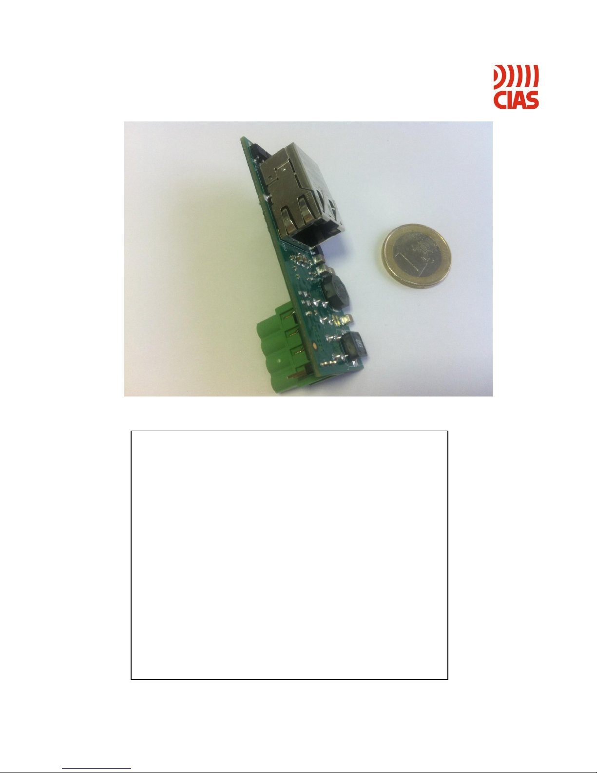
IP-DOORWAY
Convertitore Ethernet – RS485
Manuale d’installazione
Ethernet – RS485 Converter
Installation Handbook
Edizione / Edition 1.1
Page 2

INDICE
1 DESCRIZIONE ......................................................................................................................................................... 3
1.1 DESCRIZIONE DELL’APPARECCHIO .......................................................................................................................... 3
2 INSTALLAZIONE ................................................................................................................................................... 4
2.1 CONNESSIONI .......................................................................................................................................................... 4
2.1.1 Connessione alla rete Ethernet ...................................................................................................................... 4
2.1.2 Connessione ai dispositivi .............................................................................................................................. 4
2.2 POSIZIONAMENTO ................................................................................................................................................... 6
3 CONFIGURAZIONE ............................................................................................................................................... 7
3.1 CONFIGURAZIONE MEDIANTE WEB SERVER ........................................................................................................ 7
3.2 SOFTWARE DI CONFIGURAZIONE OPZIONALI............................................................................................................ 9
3.2.1 Ricerca dispositivi .......................................................................................................................................... 9
3.2.2 Assegnazione indirizzi .................................................................................................................................... 9
3.3 IMPOSTAZIONE PARAMETRI DI LAVORO ................................................................................................................... 10
3.4 CONFIGURAZIONE DELLA RETE ............................................................................................................................... 10
3.5 CONFIGURAZIONI SPECIALI ..................................................................................................................................... 10
4 RICERCA GUASTI .................................................................................................................................................. 11
5 CARATTERISTICHE .............................................................................................................................................. 11
Page 3

INDEX
1 DESCRIPTION ......................................................................................................................................................... 12
1.1 DESCRIPTION OF THE DEVICE ................................................................................................ .................................. 12
2 INSTALLATION ...................................................................................................................................................... 13
2.1 CONNECTIONS ......................................................................................................................................................... 13
2.1.1 Connections to the Ethernet network ........................................................................................................... 13
2.1.2 Connections to the devices ........................................................................................................................... 13
2.2 POSITIONING ........................................................................................................................................................... 15
3 CONFIGURATION .................................................................................................................................................. 16
3.1 CONFIGURATION USING A WEB SERVER .............................................................................................................. 16
3.2 OPTIONAL SOFTWARE CONFIGURATION.................................................................................................................. 18
3.2.1 Search for devices ........................................................................................................................................ 18
3.2.2 Address assignment ...................................................................................................................................... 18
3.3 SETTING OPERATING PARAMETERS.......................................................................................................................... 19
3.4 NETWORK CONFIGURATION .................................................................................................................................... 19
3.5 SPECIAL CONFIGURATIONS ...................................................................................................................................... 19
4 FAULT FINDING ..................................................................................................................................................... 20
5 CHARACTERISTICS .............................................................................................................................................. 20
Page 4
CIAS Elettronica S.r.l. Ed 1.1
Manuale di Installazione Pagina 3 di 20 IP-DOORWAY
1 DESCRIZIONE
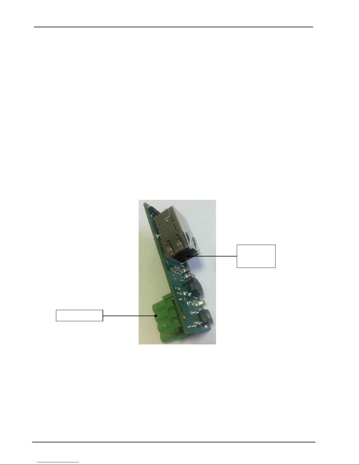
1.1 Descrizione dell’apparecchio
IP-DOORWAY è un convertitore di linea RS485 – Ethernet progettato espressamente per essere
inserito nei dispositivi:
- Ermo 482 X-PRO
- Coral Plus
- Manta
- Phytagoras
- Murena
E’ disponibile nella versione PoE Standard (IP-DOORWAY-S), in grado di essere alimentato da
uno SWITCH PoE Standard, e nella versione PoE CIAS (IP-DOORWAY-C), in grado di essere
alimentato dall’esterno con la tensione standard 13,8V DC.
In entrambi i casi IP-DOORWAY è in grado di alimentare a sua volta il dispositivo su cui è
montato e consente il collegamento diretto verso la rete ethernet di dispositivi nativi su RS485.
Nel caso di installazioni preesistenti di barriere, con alimentazione già presente nella barriera
stessa, per effettuare il collegamento verso la rete Ethernet occorre utilizzare IP-DOORWAY-C
avendo cura di aprire i ponticelli S1, S2, S4, S5.
NB1: Se le barriere hanno già un’alimentazione propria:
Non connettere mai l’IPDORWAY-C senza aver prima aperto i ponticelli S1, S2, S4, S5.
Non connettere l’IP-DOORWAY-S
NB2: Non connettere mai ad uno switch PoE un IP-DOORWAY-C
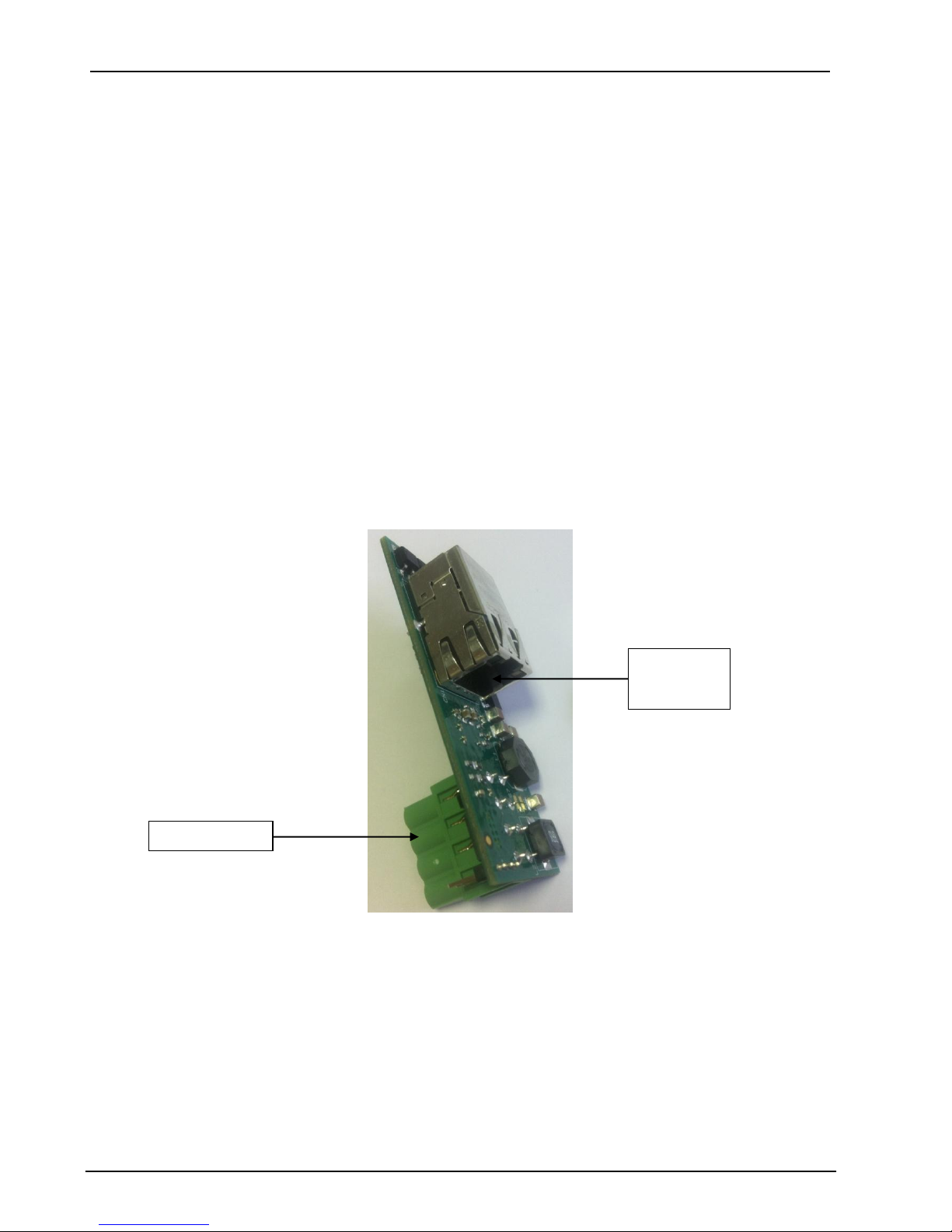
Porta
Ethernet
Porta RS-485
Page 5
CIAS Elettronica S.r.l. Ed 1.1
Manuale di Installazione Pagina 4 di 20 IP-DOORWAY
2 INSTALLAZIONE
2.1 Connessioni
2.1.1 Connessione alla rete Ethernet
Di seguito sono indicate diverse modalità di connessione alla rete in funzione del tipo di
connessione disponibile (con PoE o senza PoE).
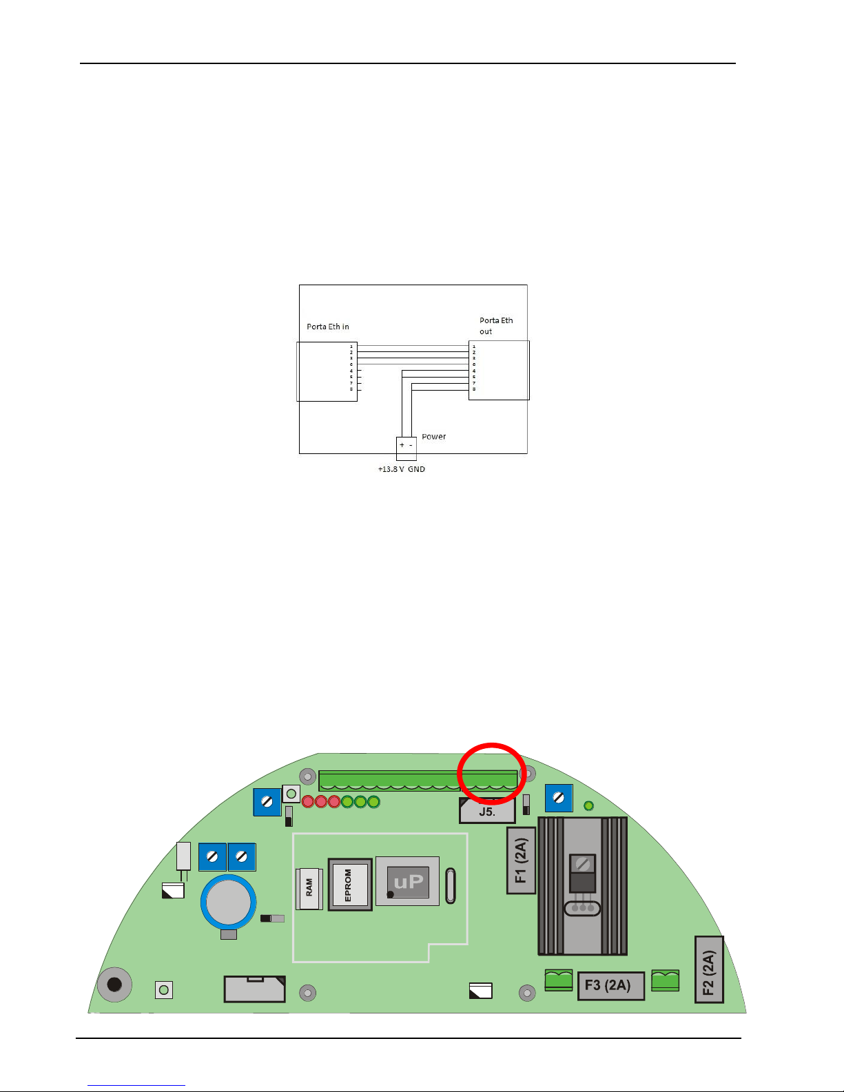
Se si dispone di uno switch con PoE effettuare la connessione diretta tra IP-DOORWAY-S
e la porta dello swtch.
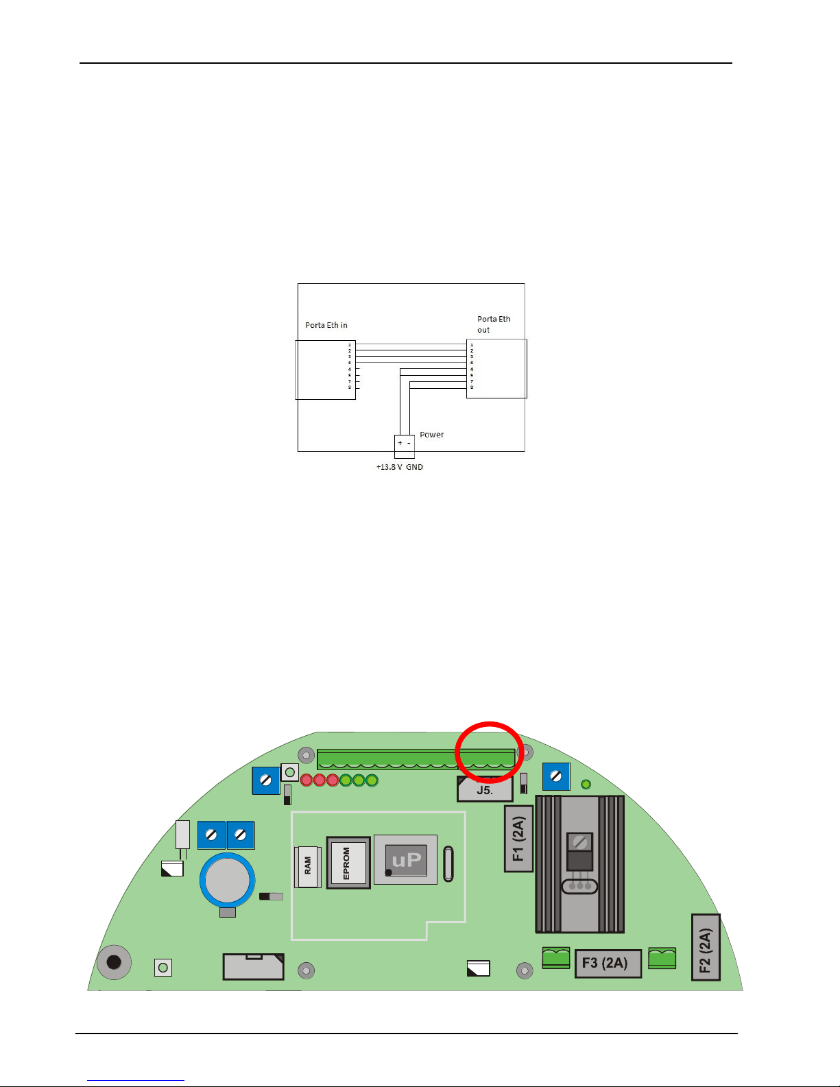
Se si dispone di switch senza PoE utilizzare IP-COORWAY-C connesso come in figura
Se si dispone di switch senza PoE e la barriera ha la propria alimentazione (Ermo482X
Pro, Coral Plus, Pythagoras) utilizzare IP-DOORWAY-C, aprire i ponticelli S1, S2, S4, S5
e successivamente effettuare la connessione tra IPDoorway-C e lo switch con cavo di
rete.
Non connettere mai l’IPDORWAY-C senza aver prima aperto i ponticelli S1, S2, S4,
S5.
Non Utilizzare l’IP-DOORWAY-S
2.1.2 Connessione ai dispositivi
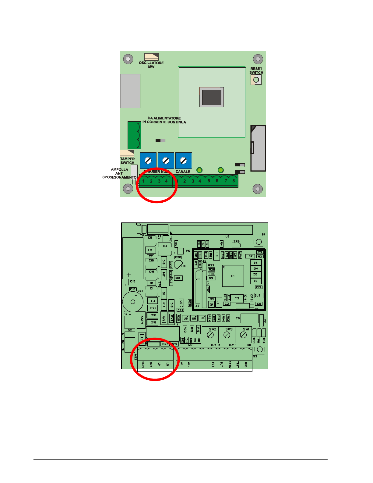
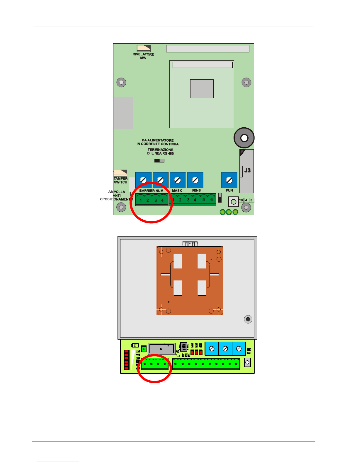
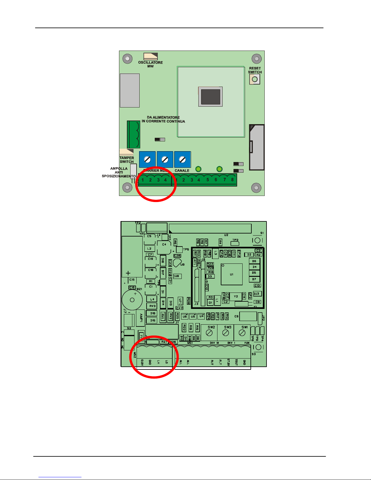
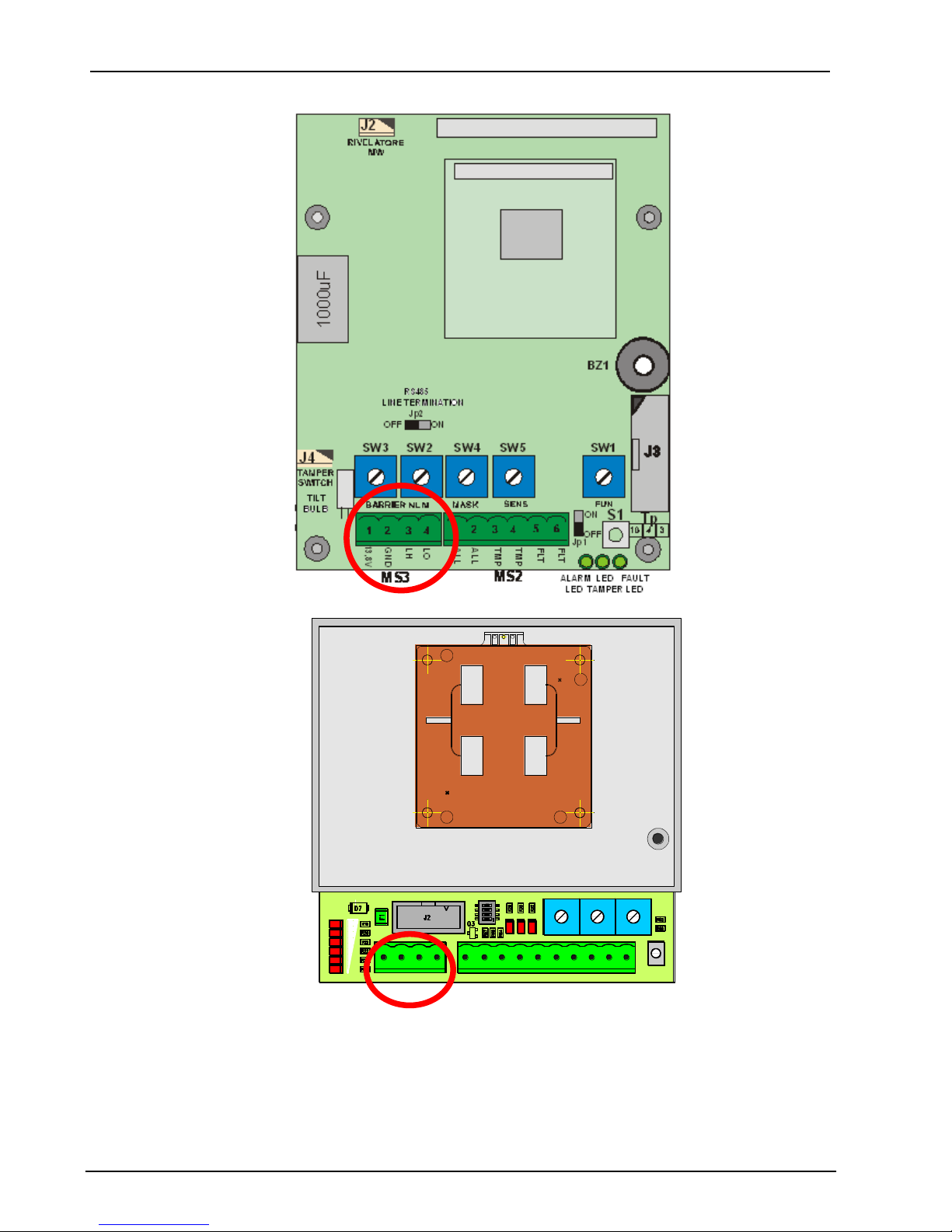
Per collegare IP-DOORWAY ad un dispositivo, inserire IP-DOORWAY nel connettore della linea
seriale RS-485 del dispositivo stesso indicato in ROSSO nelle figure sotto riportate (rispettare la
polarizzazione del connettore):
- Ermo 482 X-PRO
AMP1
MS1
MS2
J3
J4
JP5
SW3
SW2
SW1
S3
D 17
S 1
J1
112 233445678910
ING
GND
TEST
ST.BY
GTS2
GTS1
PT 2
PT 1
ALL2
ALL1
L0LHGND1
13,8V
GND1
1
2
+13,8 V
1
2
19V~
19V~
D7D9
D6 D8
D10
D11
MS3
MS4
1
1
Jp4
Batteria
BackUp 1
Jp3
Page 6
CIAS Elettronica S.r.l. Ed 1.1
Manuale di Installazione Pagina 5 di 20 IP-DOORWAY
- Coral Plus
JP2 LED
ON OFF
SYNC
Jp1
TERMINAZIONE
DI LINEA RS 485
ON
J4P
OFF
OUT
IN
13,8V
GND
MPR
1
2
3
1000uF
MS1
J3
J2
J4
S1
FLT
STBY
TEST
GND
SYNC
FLT
TMP
TMP
L0
LH
GND
13,8V
MS2
MS3
SW2
SW1
SW3
LED
GUASTO
LED
TAMPER
- Manta
1
TMP
TMP
Page 7
CIAS Elettronica S.r.l. Ed 1.1
Manuale di Installazione Pagina 6 di 20 IP-DOORWAY
- Phytagoras
LED
TAMPER
LED
GUASTO
LED
ALLARME
ON
OFF
Jp1
1000uF
J2
J4
S1
FLT
FLT
TMP
ALL
ALL
TMP
SW5SW4 SW1
BZ1
Tp
MS2
MS3
13,8V
GND
LH
LO
ON OFF
Jp2
SW2
SW3
- Murena
1
2 3
4
1 2 3 4 5 6 7 8 9 10
MS2 MS1
+13,8
GND LH LO AL AL TMP TMP FLT FLT STBY TST GND SYNC
DEV10 DEV1 FUN
S1
SW4
SW3 SW2 SW1
DL7
DL8
DL9
DL1
DL2
DL3
DL4
DL5
DL6
ON
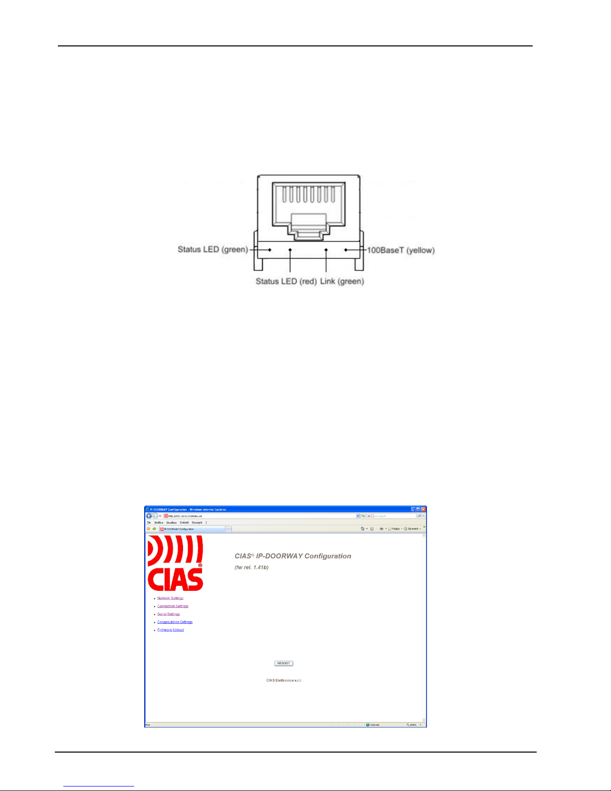
2.2 Posizionamento
Il connettore previsto su IP-DOORWAY è dotato di alette di ancoraggio, consente quindi di
inserire il modulo sul sensore senza richiedere ulteriori fissaggi.
Page 8
CIAS Elettronica S.r.l. Ed 1.1
Manuale di Installazione Pagina 7 di 20 IP-DOORWAY
3 Configurazione
IP-DOORWAY non richiede di effettuare settaggi direttamente sulla scheda: tutte le impostazioni
vengono fatte attraverso l’apposito pannello software, accessibile da un qualsiasi browser.
Installare IP-DOORWAY come indicato sopra, collegare il cavo di rete e alimentare
l’apparecchiatura attraverso l’alimentazione standard 13,8V DC oppure tramite uno switch PoE
standard a seconda della versione di IP-DOORWAY utilizzata. Se il cavo è collegato
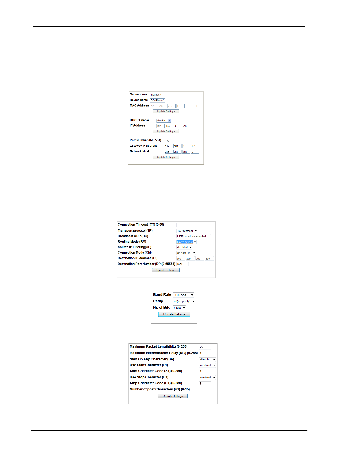
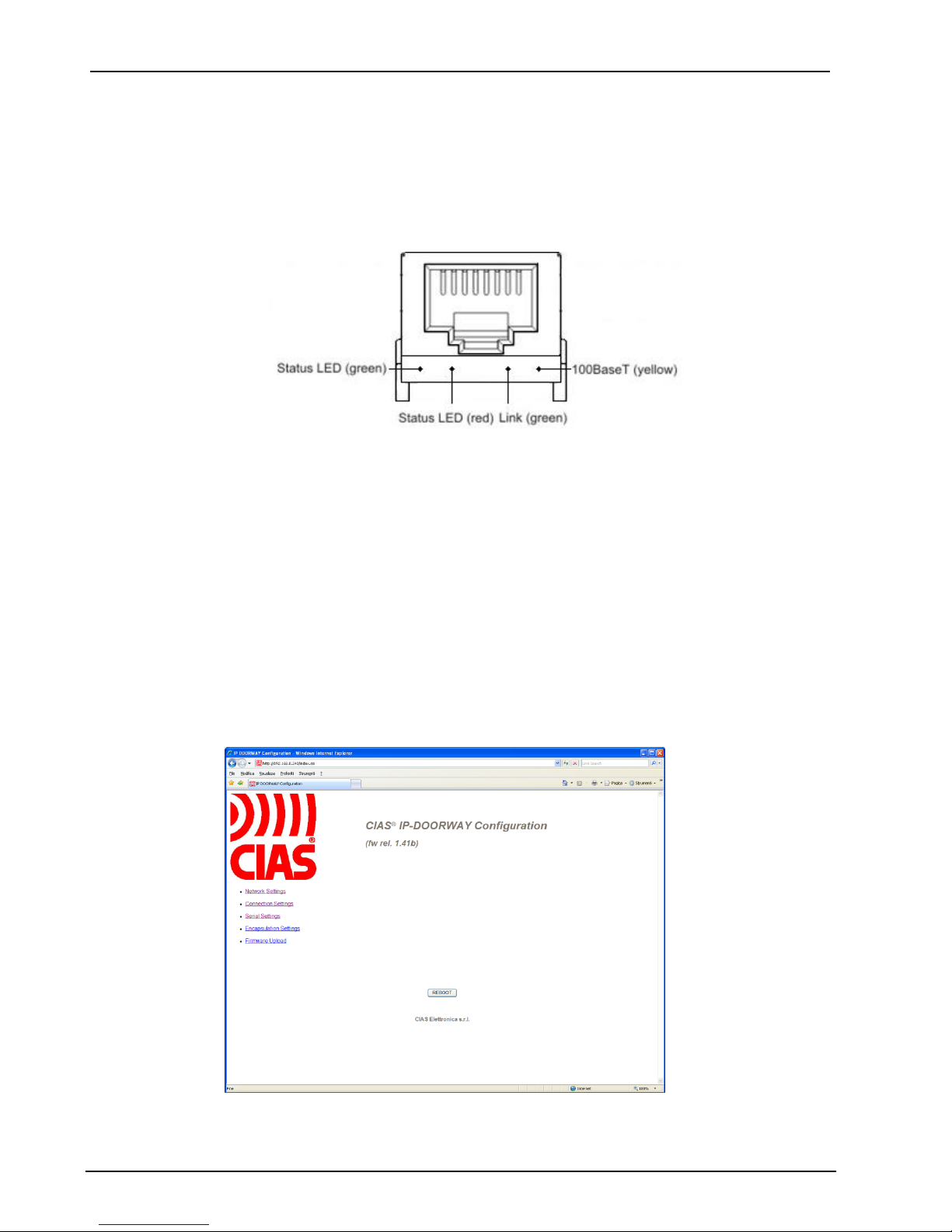
correttamente, deve accendersi l’indicatore verde link.
Il led giallo 100BaseT si accende se la rete supporta la trasmissione dati a 100Mb/s. Installare e
collegare alla rete tutti gli adattatori IP-DOORWAY che compongono l’impianto.
3.1 Configurazione mediante WEB SERVER
IP-DOORWAY è dotato di WEB SERVER integrato, grazie al quale attraverso un normale
browser è possibile modificare tutti i parametri del IP-DOORWAY stesso.
Per configurare IP-DOORWAY è necessario alimentare IP-DOORWAY, attraverso uno switch
PoE standard (se IP-DOORWAY-S), oppure con una alimentazione 13,8Vdc nel caso di IPDOORWAY-C, una volta alimentato effettuare la connessione ad una rete ethernet, aprire il
browser di Explorer digitando l’indirizzo IP 192.168.1.189. Il PC con il browser utilizzato per la
connessione deve avere i primi 3 byte dell’indirizzo IP a 192.168.1.
Verrà visualizzata la pagina del web server attraverso la quale sarà possibile modificare la
configurazione del prodotto.
Page 9
CIAS Elettronica S.r.l. Ed 1.1
Manuale di Installazione Pagina 8 di 20 IP-DOORWAY
In questa sezione è possibile modificare i parametri dell’IP-DOORWAY:
Network Settings
Connection Settings
Serial Settings
Encapsulation Settings
a. selezionare: Network Settings
E’ possibile definire l’eventuale nuovo indirizzo IP, con il quale individuare lo specifico IPDOORWAY sulla rete, oppure abilitare il DHCP
E’ possibile definire un NAME DEVICE ed un OWNER NAME in modo da caratterizzare lo
specifico IP-DOORWAY e permetterne una semplice individuazione una volta connessi da
remoto, attraverso la rete ethernet.
b. Connection settings
c. Serial settings
d. Encapsulation Settings
Al termine delle modifiche premere il pulsante REBOOT per renderle operative sul dispositivo.
Page 10

CIAS Elettronica S.r.l. Ed 1.1
Manuale di Installazione Pagina 9 di 20 IP-DOORWAY
3.2 Software di configurazione opzionali
E’ comunque possibile accedere alla configurazione di IP-DOORWAY attraverso i SW della CIAS
per la configurazione dei dispositivi con interfaccia ethernet, per esempio:
- IB-ETH-CONF
- IB-SYSTEM IP (funzionalità CONFIGURATORE CIAS TS)
Accertarsi che il PC che si sta utilizzando, abbia un indirizzo IP appartenente alla rete a cui esso
è connesso in quel momento, quindi avviare il SW per gestire la configurazione e riferirsi al
manuale dello specifico SW, per effettuare le fasi di:
- RICERCA DISPOSITIVI
- ASSEGNAZIONE INDIRIZZI
- IMPOSTAZIONE PARAMETRI DI LAVORO
3.2.1 Ricerca dispositivi
Premere il tasto search devices, per individuare automaticamente tutte le interfacce IPDOORWAY connesse alla rete e visibili dal PC che si sta utilizzando. Nel caso in cui la lista non
fosse completa controllare il collegamento delle interfacce alla rete ed eventualmente la
presenza di infrastrutture di rete (router, firewall, proxy, etc.) in grado di bloccare i pacchetti
utilizzati per la programmazione delle stesse in quanto inviati in broadcast (contattare
l’amministratore di rete).
Per ogni dispositivo individuato viene visualizzato: il MAC address del dispositivo, l’indirizzo IP
attualmente impostato, la porta dati utilizzata, il nome del proprietario, il nome identificativo del
dispositivo.
3.2.2 Assegnazione indirizzi
Prima di procedere alla programmazione delle interfacce è necessario assegnare gli indirizzi IP.
Gli indirizzi delle interfacce IP-DOORWAY devono appartenere alla rete in cui saranno installati.
Per assegnare un nuovo indirizzo, selezionare un dispositivo dall’elenco ed attivare la funzione di
riassegnazione dell’indirizzo IP del SW specifico.
Se viene richiesta la password per accedere al dispositivo selezionato, inserire la password o
lasciare il campo in bianco se non è stata impostata alcuna password di protezione (default).
Una volta confermata la password inserire il nuovo indirizzo IP per il dispositivo selezionato.
Procedere in questo modo fino ad aver assegnato un indirizzo IP valido ad ogni interfaccia
presente nella lista.
È possibile verificare la buona riuscita del procedimento eseguendo nuovamente una ricerca dei
dispositivi collegati.
Page 11

CIAS Elettronica S.r.l. Ed 1.1
Manuale di Installazione Pagina 10 di 20 IP-DOORWAY
3.3 Impostazione parametri di lavoro
Prima che i dispositivi IP-DOORWAY possano operare è necessario procedere all’impostazione
dei parametri di lavoro per ognuno di essi.
Selezionandolo con il SW specifico ed attivando la funzione per l’impostazione dei parametri di
lavoro, è possibile specificare per ogni dispositivo:
il tipo di protocollo utilizzato
l’indirizzo del gateway utilizzato per uscire dalla rete (nel caso non fosse presente è
consigliabile attribuire l’indirizzo di un Host non presente in rete)
il netmask della rete in cui tali dispositivi dovranno lavorare
la porta dati utilizzata
il nome caratteristico del singolo dispositivo max 8 caratteri, (default: DOORWAY)
il proprietario del dispositivo o ditta installatrice Max 8 caratteri, (default: CIAS)
Selezionare il protocollo UDP, questo viene utilizzato all’interno della rete per interconnettere i
sensori e gli elementi che compongono l’impianto di sicurezza.
Se presente nella rete un server di assegnazione indirizzi DHCP, e’ possibile abilitare la funzione
DHCP che permette, all’accensione di IP-DOORWAY, di ottenere l’indirizzo IP, il netmask della
rete e l’indirizzo del gateway in modo automatico direttamente dal server DHCP.
Attenzione: la porta dati utilizzata si può scegliere liberamente in funzione dell’architettura di
rete, le interfacce IP-DOORWAY saranno in grado di comunicare solo con dispositivi che
utilizzano lo stesso numero di porta. All’interno di una sola rete è possibile impiegare più numeri
di porta, realizzando in questo modo dei canali dati indipendenti l’uno dall’altro.
3.4 Configurazione della rete
IP-DOORWAY utilizza il protocollo UDP per inviare i dati provenienti dai sensori attraverso la rete
ethernet. Ciascun pacchetto viene inviato all’indirizzo di broadcast 255.255.255.255. Nel caso di
grandi reti informatiche, separate da firewall e router i pacchetti diretti verso l’indirizzo
255.255.255.255 (indirizzo di Broadcast) potrebbero essere bloccati. Qualora servisse
raggiungere parti di rete separata da tali dispositivi, contattare l’amministratore di rete. Anche la
programmazione degli IP-DOORWAY prevede l’utilizzo di alcuni pacchetti UDP inviati in
broadcasting, bloccando questi pacchetti potrebbe essere impossibile individuare ed impostare i
dispositivi connessi alla rete.
3.5 Configurazioni speciali
Il protocollo UDP viene utilizzato all’interno della rete locale per collegare tra loro i sensori e le
varie apparecchiature che compongono l’impianto. È possibile utilizzare IP-DOORWAY anche
per fornire un accesso all’impianto stesso dall’esterno: ad esempio per consentire ad organi di
supervisione di collegarsi all’impianto da remoto. In questo caso è possibile selezionare il
protocollo TCP nella finestra di configurazione vista sopra.
Attenzione: mentre il protocollo UDP permette di interconnettere tra loro molti apparecchi come
se fossero collegati dallo stesso filo, il protocollo TCP è in grado di collegare tra loro solo due
dispositivi (un server ed un client).
Il protocollo TCP è ulteriormente suddiviso in server e client: se impostato come server il
dispositivo attende che un altro dispositivo apra attivamente una connessione verso di lui, fino a
che non viene effettuato questo collegamento il dispositivo rimane in attesa. Se impostato come
client il dispositivo tenta di collegarsi al dispositivo specificato ed insiste in questa operazione fino
a quando non riesce.
Il protocollo TCP viene utilizzato per fornire un accesso remoto all’impianto: in questo caso
selezionare TCP-server; oppure per collegare due reti attraverso un ponte: in questo caso
impostare uno dei due apparecchi come TCP-server e l’altro come TCP-client.
Page 12

CIAS Elettronica S.r.l. Ed 1.1
Manuale di Installazione Pagina 11 di 20 IP-DOORWAY
4 RICERCA GUASTI
Difetto
Possibile Causa
Possibile Soluzione
Led verde e led giallo spenti
Mancanza alimentazione
Verificare la presenza
dell’alimentazione
Mancanza connessione cavo
Ethernet
Verificare il cavo Ethernet
Led verde acceso e led
giallo spento
Assenza comunicazione/
connessione Ethernet
Verificare il cavo e la
connessione Ethernet
5 CARATTERISTICHE
Caratteristiche tecniche IP-DOORWAY-C
Min
Nom
Max
Unit
Tensione di alimentazione (Vdc) se PoE CIAS
11.0
13.8
17.0
V
Corrente di alimentazione a 13.8V del solo IP-DOORWAY
25
45
50
mA
Temperatura di lavoro
-35 +65
°C
Linea Ethernet
10Mbit/s
100Mbit/s
bps
Baud rate – linea seriale
9600
bps
Dimensioni
73 x 28.3 x 35
mm
Caratteristiche tecniche IP-DOORWAY-S
Min
Nom
Max
Unit
Tensione di alimentazione (Vdc) se PoE Standard
21.0 57.0
V
Corrente di alimentazione a VNom
CLASS 0
mA
Temperatura di lavoro
-35 +65
°C
Linea Ethernet
10Mbit/s
100Mbit/s
bps
Baud rate – linea seriale
9600
bps
Dimensioni
73 x 28.3 x 35
mm
Page 13
CIAS Elettronica S.r.l. Ed 1.1
Installation Manual Page 12 of 20 IP-DOORWAY
1 DESCRIPTION
1.1 Description of the device
IP-DOORWAY is a RS485 – Ethernet converter designed specifically for use with the following
devices:
- Ermo 482 X-PRO
- Coral Plus
- Manta
- Phytagoras
- Murena
It is available as PoE Standard (IP-DOORWAY-S) version, able to be powered via a Standard
POE Switch, and in a PoE CIAS (IP-DOORWAY-C) version, which can be powered externally by
a standard 13.8V DC power supply.
In both cases the the IP-DOORWAY is able, in turn, to power the device on which it is mounted
and can connect native RS485 devices directly to the Ethernet network.
When adding to previously installed barriers, with power already present on the barrier, to make
the connection to the Ethernet network use the IP-DOORWAY-C and open links S1, S2, S4, S5.
NB1: If the barrier already has a power supply:
Do NOT connect the IP-DOORWAY-C without having first opened the links S1, S2, S4,
S5.
Do NOT connect the IP-DOORWAY-S
NB2: Do NOT connect the IP-DOORWAY-C to a PoE switch
Etehernet
Port
RS-485 Port
Page 14
CIAS Elettronica S.r.l. Ed 1.1
Installation Manual Page 13 of 20 IP-DOORWAY
2 INSTALLATION
2.1 Connections
2.1.1 Connections to the Ethernet network
There follows different connection methods to the network, dependent on the type of connection
available (with PoE or without PoE).
If a PoE switch is available make the connection directly between the IP-DOORWAY-S
and the port of the switch.
If a switch without PoE is available use the IP-COORWAY-C connected as shown
If a switch without PoE is available and the barrier has its own power supply (Ermo482X
Pro, Coral Plus, Pythagoras) use IP-DOORWAY-C, open the links S1, S2, S4, S5 then
make the connection between the IP-DOORWAY-C and the switch using a network cable.
Do NOT connect the IP-DOORWAY-C without having first opened the links S1, S2,
S4, S5.
Do NOT connect the IP-DOORWAY-S
2.1.2 Connections to the devices
To connect the IP-DOORWAY to a device insert the IP-DOORWAY into the connector for the
RS485 serial line on the device, as circled in red on the following figures, ensuring the correct
polarisation of the connector:
- Ermo 482 X-PRO
AMP1
MS1
MS2
J3
J4
JP5
SW3
SW2
SW1
S3
D 17
S 1
J1
112 233445678910
ING
GND
TEST
ST.BY
GTS2
GTS1
PT 2
PT 1
ALL2
ALL1
L0LHGND1
13,8V
GND1
1
2
+13,8 V
1
2
19V~
19V~
D7D9
D6 D8
D10
D11
MS3
MS4
1
1
Jp4
Batteria
BackUp 1
Jp3
Page 15
CIAS Elettronica S.r.l. Ed 1.1
Installation Manual Page 14 of 20 IP-DOORWAY
- Coral Plus
JP2 LED
ON OFF
SYNC
Jp1
TERMINAZIONE
DI LINEA RS 485
ON
J4P
OFF
OUT
IN
13,8V
GND
MPR
1
2
3
1000uF
MS1
J3
J2
J4
S1
FLT
STBY
TEST
GND
SYNC
FLT
TMP
TMP
L0
LH
GND
13,8V
MS2
MS3
SW2
SW1
SW3
LED
GUASTO
LED
TAMPER
- Manta
1
TMP
TMP
Page 16
CIAS Elettronica S.r.l. Ed 1.1
Installation Manual Page 15 of 20 IP-DOORWAY
- Phytagoras
- Murena
1
2 3
4
1 2 3 4 5 6 7 8 9 10
MS2 MS1
+13,8
GND LH LO AL AL TMP TMP FLT FLT STBY TST GND SYNC
DEV10 DEV1 FUN
S1
SW4
SW3 SW2 SW1
DL7
DL8
DL9
DL1
DL2
DL3
DL4
DL5
DL6
ON
2.2 Positioning
The connector fitted on the IP-DOORWAY is designed with mounting keys to ensure that it can
be fitted to the device without additional fixings.
Page 17
CIAS Elettronica S.r.l. Ed 1.1
Installation Manual Page 16 of 20 IP-DOORWAY
3 Configuration
IP-DOORWAY does not require any configuration on the board: all the settings are made using
the appropriate software, accessible from any browser. Instal the IP-DOORWAY as shown
above, connecting the network cable and powering the device using a standard 13.8V DC power
supply or a standard PoE switch dependent on the IP-DOORWAY used. If the cable is connected
correctly the green LINK led will illuminate.
The yellow 100BaseT led will illuminate if the network supports 100Mb/s data transmission.
Install and connect all the IP-DOORWAY that are required on the network.
3.1 Configuration using a WEB SERVER
IP-DOORWAY is provided with an integrated WEB SERVER, which means that by using a
standard browser it is possible to modify all of the properties of the connected IP-DOORWAY.
To configure the IP-DOORWAY it is necessary to power the IP-DOORWAY, using a standard
PoE switch (IP-DOORWAY-S), or with a 13.8Vdc power supply (IP-DOORWAY-C). Once powerd
make the connection to the Ethernet network, and enter the IP address 192.168.1.189.
The PC with the browser used to connect must have the first 3 bytes of the IP to 192.168.1
This will display the page from the web server that will allow modification of the device
configuration.
Page 18
CIAS Elettronica S.r.l. Ed 1.1
Installation Manual Page 17 of 20 IP-DOORWAY
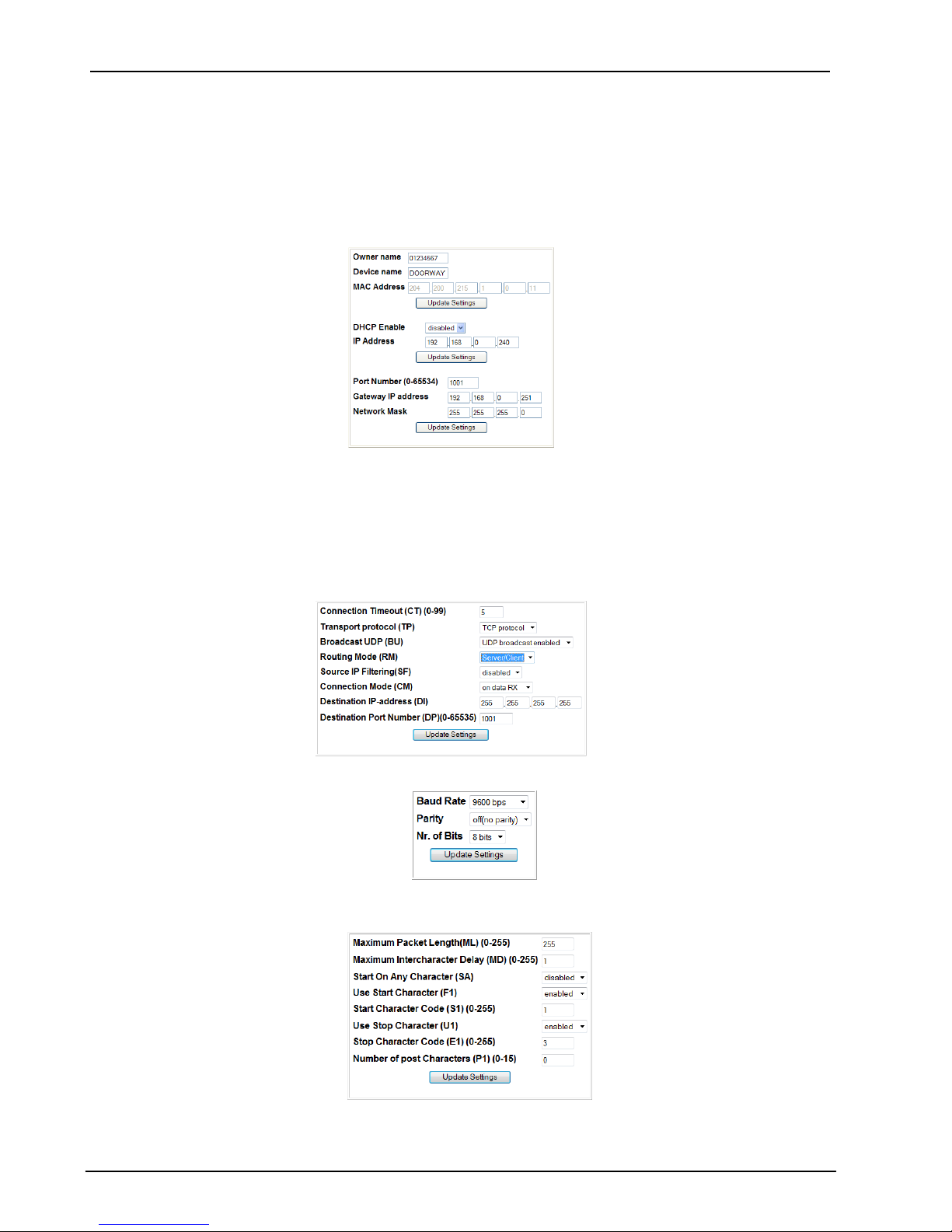
In this section it is possible to modify the IP-DOORWAY parameters:
Network Settings
Connection Settings
Serial Settings
Encapsulation Settings
a. select: Network Settings
It is possible to define the new IP address, that will be used to identify that specific IPDOORWAY on the network or enable the DHCP.
It is possible to define a DEVICE NAME and an OWNER NAME to personalise the specific
IP-DOORWAY and allow simple identification once remotely connected, via the Ethernet
network.
b. Connection settings
c. Serial settings
d. Encapsulation Settings
When modifications are complete click REBOOT to activate the configuration on the device.
Page 19

CIAS Elettronica S.r.l. Ed 1.1
Installation Manual Page 18 of 20 IP-DOORWAY
3.2 Optional Software Configuration
It is also possible to access the configuration of the IP-DOORWAY using CIAS software for
Ethernet device configuration, such as:
- IB-ETH-CONF
- IB-SYSTEM IP (CIAS TS CONFIGURATOR)
Ensure that the PC to be used has a correct IP address for the network that it is going to be
connected to, then launch the appropriate software and refer to the specific software manual for
information on how to:
- SEARCH FOR DEVICES
- ADDRESSES ASSIGNMENT
- SET OPERATING PARAMETERS
3.2.1 Search for devices
Click the search devices button to automatically identify all the IP-DOORWAY devices
connected to the network and visible to this PC. If the list is not complete check the the
connections of the interface to the network and also the presence of any network devices (router,
firewall, proxy,..), which could block the programming packets sent in broadcast mode (contact
the network administrator).
For each device identified it is possible to display: the MAC address of the device, the actual IP
address, the port used, the owner’s name and the device name.
3.2.2 Address assignment
Before programming the device it is necessary to assign an IP addresses. The addresses of the
IP-DOORWAY must be within the network on which they are installed.
To assign a new address select a device from the list and activate the address re-assignment
option from the specific software being used.
If a password will be required to access the device selected enter the password or leave the field
blank if a protection password is not required (default).
Once confirmed enter a new IP address for the selected device.
Repeat this process until the correct IP addresses have been assigned to every device on the
list.
It is possible to verify the correct settings by repeating the search devices command.
Page 20

CIAS Elettronica S.r.l. Ed 1.1
Installation Manual Page 19 of 20 IP-DOORWAY
3.3 Setting operating parameters
Before the IP-DOORWAY devices can work it is necessary to set the working parameters for
each device.
Selecting the parameter setting function within the specific software will allow the following
operating parameters to be set for each device:
The type of protocol used
The address of the gateway used to exit the network (if this is not present it is
recommended to assign an address of a Host not present on the network)
The net mask of the network in which the device will operate
The data port used
The device name with a maximum of 8 characters (default: DOORWAY)
The owner or installer of the device with a maximum of 8 characters (default: CIAS)
Select the UDP protocol, which is used within the network to interconnect the sensors and the
elements that make up the security system.
If there is a DHCP server on the network, which assigns the addresses, it is possible to enable
the DHCP function which allows, when the IP-DOORWAY are powered up, the IP addresses, the
net mask of the network and the gateway to be obtained automatically from the DHCP server.
Attention: the data port used can be freely chosen, dependent on the network architecture, and
the IP-DOORWAY are only able to communicate with devices with the same data port number.
Inside the network it is possible to to set multiple port numbers, creating a series of independent
communication channels.
3.4 Network configuration
IP-DOORWAY uses the UDP protocol to send the data provided by the sensors across the
network. Each packet is sent to the broadcast address 255.255.255.255. In the case of large
information networks, separated by firewalls and routers, packets sent to the broadcast address
255.255.255.255 can possibly be blocked. If these devices separate the devices from part of the
network contact the network administrator. Also the programming of the IP-DOORWAY requires
the use of the UDP packets sent in broadcast mode and blocking these packets will make it
impossible to to identify and set up the devices connected to the network.
3.5 Special configurations
The UDP protocol is used inside the local network to connect between the sensors and the
various equipment which makes up the system. It is also possible to use the IP-DOORWAY to
provide access to the system from outside: for example to allow a monitoring company to collect
data remotely. In this case it is possible to select the TCP protocol in the configuration window.
Attention: while the UDP protocol is able to connect between multiple devices as if they are
connected to the same wire, the TCP protocol is only able to connect between two devices (a
server and a client).
The TCP protocol divided into server and client: if set as a server the device waits until another
device actively tries to establish communications with it and until this connection is made the
device remains in the listening mode. If set as a client the device tries to establish
communications with a specific device and keeps trying until successful.
The TCP protocol is used to provide remote access to the system: in this case select TCP-server;
or to connect two networks via a bridge: in this case set one of the two devices as TCP-server
and the other as TCP-client.
Page 21

CIAS Elettronica S.r.l. Ed 1.1
Installation Manual Page 20 of 20 IP-DOORWAY
4 FAULT FINDING
Fault
Possible Cause
Possible Solution
Green and yellow LED off
No power supply
Check power supply and
connections
No connection to Ethernet cable
Check Ethernet cable
Green LED on and yellow
LED off
No communication/connection to
Ethernet
Check Ethernet cable and
connection
5 CHARACTERISTICS
Technical Characteristics IP-DOORWAY-C
Min
Nom
Max
Unit
Power supply voltage (Vdc) if PoE CIAS
11.0
13.8
17.0
V
Current consumption at 13.8V of one IP-DOORWAY
25
45
50
mA
Operating Temperature
-35 +65
°C
Ethernet line
10Mbit/s
100Mbit/s
bps
Baud rate – serial line
9600
bps
Dimensions
73 x 28.3 x 35
mm
Technical Characteristics IP-DOORWAY-S
Min
Nom
Max
Unit
Power supply voltage (Vdc) if PoE Standard
21.0 57.0
V
Current consumption at VNom
CLASS 0
mA
Operating Temperature
-35 +65
°C
Ethernet line
10Mbit/s
100Mbit/s
bps
Baud rate – serial line
9600
bps
Dimensions
73 x 28.3 x 35
mm
Page 22

I
Con la presente, CIAS Elettronica, dichiara che questi apparati “ IP-DOORWAY-C ” e“ IP-DOORWAY-S ” sono conformi ai
requisiti essenziali ed alle altre disposizioni rilevanti della Direttiva 1999/5/CE (Art.3.1a-3.1b-3.2)
Hereby, CIAS Elettronica, declares that these products “ IP-DOORWAY-C ” and “ IP-DOORWA-S ” are in compliance with
the essential requirement and other relevant provisions of Directive 1999/5/EC (Art.3.1a-3.1b-3.2)
Questo apparecchio è contrassegnato in conformità alla Direttiva Europea 2002/96/EC, Waste Electrical and Electronic
Equipment (WEEE)
Assicurarandosi che questo prodotto sia smaltito in modo corretto, l’utente contribuisce a prevenire le potenziali conseguenz e
negative per l’ambiente e la salute.
Il simbolo sul prodotto o sulla documentazione d’accompagnamento indica che questo prodotto non deve essere trattato
come rifiuto domestico ma deve essere consegnato presso l’idoneo punto di raccolta per il riciclaggio d’apparecchiature
elettriche ed elettroniche.
Disfarsene seguendo le normative locali per lo smaltimento rifiuti.
Lo smaltimento abusivo è punito con le sanzioni previste dalla legislazione nazionale vigente
Il prodotto può essere riconsegnato al distributore/installatore a fine vita in occasione di un nuovo acquisto.
This product is marked in compliance with the European Directive 2002/96/EC, Waste Electrical and Electronic Equipment
(WEEE).
The correct disposal of the product will prevent potential negative consequences for the environment and the human health.
The symbol on the product or into the annexed documentation indicates that this product does not have to be dealt like
domestic refusal but must be delivered near the suitable point of collection for the recycling of electrical and electronic
equipment.
The illicit disposal will be endorsed according to local l regulations.
At the end of operative life the product can be given back to the vendor/installation organization in occasion of a new purchase.
Copyright CIAS Elettronica S.r.l.
Stampato in Italia / Printed in Italy
CIAS Elettronica S.r.l.
Direzione, Ufficio Amministrativo, Ufficio Commerciale, Laboratorio di Ricerca e Sviluppo
Direction, Administrative Office, Sales Office, Laboratory of Research and Development
20158 Milano, via Durando n. 38
Tel. +39 02 376716.1
Fax +39 02 39311225
Web-site: www.cias.it
E-mail: [email protected]
Stabilimento / Factory
23887 Olgiate Molgora (LC), Via Don Sturzo n. 17
 Loading...