

Page 1
Personal computer
µATX
form factor
Intel® D945GTP
motherboard
Discovery / Enterprise TP
Quality | Perform a n c e | Service www.C I A R A - T E C H . c o m
User Guide
Page 2

Ciara Enterprise/Discovery 945GTP
Ciara Technologies Inc. (CIARATECH)
9300 Trans Canada Highway
Montreal, Quebec H4S 1K5
Tel: (514) 798-8880
Fax: (514) 798-8889
• Microsoft, Windows 2000 and Windows XP are registered trademarks of Microsoft Corporation
• Intel and Pentium
®
are registered trademarks of Intel Corporation
• Novell and NetWare are registered trademarks of Novell Corporation
• All other names, brands, and trademarks are trade marks of their re spective companie s
First Printing December 2005
Printed in Canada
- 2 -
Page 3

Ciara Enterprise/Discovery 945GTP
TABLE OF CONTENTS
COMPATIBILITY....................................................................................................7
ONE YEAR LIMITED WARRANTY...........................................................................8
Procedures to be followed: ....................................................................................................................9
LIMITED WARRANTY ....................................................................................................................... 10
RADIO INTERFERENCE PRECAUTIONS...............................................................11
DECLARATION OF CONFORMITY .....................................................................12
FCC INFORMATION TO USER ............................................................................13
1.0: INTRODUCTION TO THE CIARA ENTERPRISE/DISCOVERY 945GTP............14
1.1: Upgrading........................................................................................................................................17
1.2: Networking......................................................................................................................................17
2.0: THE CIARA ENTERPRISE/DISCOVERY 945GTP BIOS...................................18
2.1: BIOS Configuration and Installation......................................................................................... 18
2.2: BIOS Set-up Program Menu Bar .................................................................................................19
2.3: BIOS Set-up Program Function Keys ......................................................................................... 19
2.4: PCI Autoconfiguration..................................................................................................................19
2.5: PCI IDE Support............................................................................................................................. 19
2.6: System Management BIOS (SMBIOS).......................................................................................20
2.7: Legacy USB Support...................................................................................................................... 20
2.8: BIOS Updates..................................................................................................................................21
2.8.1 Language Support.............................................................................................................. 21
2.8.2 Custom Splash Screen........................................................................................................ 21
2.9: Boot Options ...................................................................................................................................22
2.9.1 CD-ROM Boot.....................................................................................................................22
2.9.2 Network Boot......................................................................................................................22
2.9.3 Booting with attached devices.......................................................................................... 22
2.9.4 Changing the Default Boot Device During POST..........................................................22
2.10: Fast Booting Systems with Intel Rapid BIOS Boot................................................................23
2.10.1 Peripheral Selection and Configuration.......................................................................... 23
2.10.2 Intel Rapid BIOS Boot ........................................................................................................ 23
2.11: BIOS Security Features................................................................................................................24
3.0: CIARA ENTERPRISE/DISCOVERY 945GTP SPECIFICATIONS...................... 25
3.1: Configuration & Layout - Ciara Enterprise/Discovery 945GTP Main board...................... 25
3.2: The PCI Express Bus...................................................................................................................... 28
3.3: Disk Drives......................................................................................................................................28
Floppy Drives .....................................................................................................................................28
Hard Disk Drives................................................................................................................................28
CD-ROM Drives ................................................................................................................................. 28
3.4: Keyboard.......................................................................................................................................... 28
3.5: Intel GMA950 Video Set-up.........................................................................................................29
Installing Utility and Driver Software............................................................................................. 29
DPMS Settings ....................................................................................................................................29
3.6: Audio Set-up ...................................................................................................................................29
- 3 -
Page 4

Ciara Enterprise/Discovery 945GTP
3.7: I/O Port Set-up................................................................................................................................ 29
3.8: Intel® Active Management Technology (Optional)................................................................ 30
4.0: INSTALLING AND UPGRADING YOUR SYSTEM ..........................................32
4.1: Unpacking Your Computer.......................................................................................................... 32
4.2: Choosing a Site for the System.................................................................................................... 32
4.3: Connecting I/O Devices................................................................................................................ 34
4.4: Installing Adapter Cards .............................................................................................................. 35
4.5: Replacing the System Batteries................................................................................................... 35
4.6: Installing an Upgrade CPU.......................................................................................................... 35
4.7: Installing an Upgrade Flash BIOS.............................................................................................. 35
4.8: Installing DIMM Memory Modules .......................................................................................... 36
Memory Bank Configuration ........................................................................................................... 36
Installing DIMM Modules ................................................................................................................ 37
4.9: System Maintenance ..................................................................................................................... 38
5.0: USING THE CIARA ENTERPRISE/DISCOVERY 945GTP ................................39
5.1: Introduction .................................................................................................................................... 39
5.2: A Caution about Viruses .............................................................................................................. 39
5.3: Windows.......................................................................................................................................... 39
5.4: Windows 2000 Server, Windows 2003 Server & Novell NetWare.........................................39
6.0: DOCUMENTING YOUR COMPUTER............................................................40
6.1: Base System Details....................................................................................................................... 41
6.2: Hardware Configuration ..............................................................................................................41
7.0: QUICK INSTALLATION GUIDE ....................................................................42
7.1: Mid-Tower Chassis Characteristics............................................................................................ 42
7.2: Small Form Factor Chassis Characteristics................................................................................ 43
7.3 : Opening and accessing the chassis............................................................................................ 44
7.4: Preparing the chassis for installation......................................................................................... 46
7.5: Insertion of the motherboard....................................................................................................... 48
7.6: Insertion of the processor............................................................................................................. 49
7.7: Installation of the optical drive module .................................................................................... 51
7.8: Installation of the hard drive ....................................................................................................... 52
7.9: Installation of the floppy drive ................................................................................................... 54
7.10: Power Considerations ................................................................................................................. 55
7.11: Connecting the keyboard ...........................................................................................................56
7.12: Connecting the mouse................................................................................................................. 57
7.13: Connecting the LCD Monitor.................................................................................................... 58
7.14: Connecting the headset to the front panel of the chassis ..................................................... 59
7.15: Connecting the headset and speakers to the back of the chassis........................................ 60
7.16: Installation of the memory modules ........................................................................................61
7.17: Installation of the network card................................................................................................ 62
7.18: Precautions against static electricity......................................................................................... 63
8.0: TROUBLESHOOTING YOUR SYSTEM............................................................64
8.1: BIOS Errors and Messages........................................................................................................... 64
8.2: Beep Codes...................................................................................................................................... 64
8.3: Helpful hints................................................................................................................................... 65
8.4: Solving General Problems ........................................................................................................... 66
8.5: Solving Power Supply Problems ................................................................................................ 67
8.6: Solving Diskette Problems........................................................................................................... 69
8.7: Solving Hard Drive Problems .....................................................................................................70
8.8: Solving Display Problems............................................................................................................ 71
- 4 -
Page 5

Ciara Enterprise/Discovery 945GTP
8.9: Solving Audio Problems............................................................................................................... 73
8.10: Solving Printer Problems............................................................................................................73
8.11: Solving Keyboard and Mouse Problems ................................................................................. 74
8.12: Solving Hardware Installation Problems ................................................................................ 75
8.13: Solving Memory Problems......................................................................................................... 76
8.14: Solving Processor Problems.......................................................................................................76
8.15: Solving Optical Drive Problems................................................................................................77
GLOSSARY .........................................................................................................78
- 5 -
Page 6

Ciara Enterprise/Discovery 945GTP
ABOUT THIS GUIDE
Please read this User's Guide before using your Ciara Enterprise/Discovery 945GTP computer. If you are an
experienced user then you may wish to proceed to Chapters 2, 4 & 5.
This User's Guide is divided into eight chapters that provide information on Models, Features and Upgrades,
Hardware Specifications, Set-up, Configuration, and Installation, as well as an Equipment Log and a Glossary.
Please remember to fill out the Equipment Log that you will find in Chapter 6, and keep a copy in a safe place.
Chapter 1 will stimulate your desire to learn more about the many exciting upgrades and enhancements, including
PCI Express video cards, PCI Express add-in cards and conventional PCI sound controllers and disk controllers that
we offer for your Ciara Enterprise/Discovery 945GTP computer. Please contact us at Ciara Technologies Inc. for
any additional details.
With proper care and operating procedures your Ciara Enterprise/Discovery 945GTP will give many years of service
and high performance computing.
- 6 -
Page 7

Ciara Enterprise/Discovery 945GTP
COMPATIBILITY
All Ciara Enterprise/Discovery 945GTP models run the following operating systems software:
• MS-Windows (All Versions, including 2000 and XP)
• SCO UNIX/ Open Desktop
• Linux
Ciara’s Enterprise/Discovery 945GTP models will operate on Windows NT Server, Windows 2000 Server,
Windows 2003 Server, Novell NetWare, SCO Unix and all UNIX
network adapter cards and applications software have been installed.
Ciara Technologies Inc. is licensed to supply the Windows 2000 and Windows XP operating systems software with
it’s Ciara Enterprise/Discovery 945GTP computers. A package of the latest version of Windows software and a
manual is included with the Ciara Enterprise/Discovery 945GTP.
If you have purchased a Windows license with your Ciara Enterprise/Discovery 945GTP system, please abide by the
Copyright and License terms and conditions that are enclosed with this software package. These require that the
Windows software may only be used and installed on the Ciara Enterprise/Discovery 945GTP computer with which
they were purchased.
You may make copies of this Windows software for your own back-up purposes only.
All Ciara Enterprise/Discovery 945GTP series computers are certified by the Canadian Standards Association
(CSA), and meet or exceed the Class B limitations for Radio noise emissions from digital apparatus as set out in the
Radio Interference Regulations of Industry Canada.
based networks, provided that appropriate
- 7 -
Page 8

Ciara Enterprise/Discovery 945GTP
ONE YEAR LIMITED WARRANTY
Ciara Technologies Inc. customarily provides a one (1) year, 100% parts and labour non-transferable and limited
warranty to all Original Purchasers of its Enterprise/Discovery 945GTP series computers. The warranty terms are
normally Return-to-Depot. This one-year limited warranty starts on the "Date of Delivery". The warranty covers any
optional product(s) manufactured and sold by Ciara Technologies Inc. and installed by Ciara Technologies Inc. in
an Enterprise/Discovery 945GTP series System Unit. This one-year limited warranty, however, does not apply to
any other item not internally installed in the System Unit by Ciara Technologies Inc., or to any subsequent owners.
If you have purchased a different type of warranty, or an extension to the standard warranty, you will need to
provide the Ciara Technologies Inc. Service Contract Number to the Customer Support representative when placing
a call for service or support. It is advisable to affix this Contract Number to the machine in the event that service is
required.
In lieu of either the On-Site or Return-to-Depot portions of the warranty, Ciara Technologies Inc. reserves the right
to directly ship certain customer replaceable components as replacement products for failed components. When this
option is invoked, the customer will be asked to replace the component(s) and return the original failed component
to Ciara Technologies Inc. within five (5) working days.
- 8 -
Page 9

Ciara Enterprise/Discovery 945GTP
Procedures to be followed:
1. Refer to the back of your system main CPU unit and record the model number and serial number from the
Machine Identification Label.
2. Make sure that you know the name and version number of the operating system that you are using, what
accessory expansion cards you have installed in your system, and that you have the system Owner’s and
User’s Guides ready to hand.
3. Call Ciara Technologies’ Support Centre at 877-242-7272.
4. Provide the computer system’s model number and serial number. If you have purchased an extended
warranty, please provide the Service Contract number as well. The Customer Service Representative will
verify your warranty status immediately, and then pass the call to the dedicated PC Support Group for
further action.
5. Answer any questions from the support personnel to the best of your ability: The support group may ask
you to provide additional information, run specific commands, change or verify parameter settings, etc…
6. The support personnel may be able to rectify the problem over the telephone, at which time you should
ask for and record the unique call number for your own records. If the support group is unable to resolve
the problem remotely, an On-Site call may be generated or additional information will be provided to you
to obtain a Returned Merchandise Authorization Number (RMA), depending upon the type and current
status of your warranty.
7. Make a back-up copy of all of the files on your hard disk before returning your computer for service.
Ciara Technologies Inc. is not responsible for the loss or damage of any data on the returned system. In
some cases, hard disks may need to reformatted or replaced. It is the responsibility of the user to ensure
data is backed up prior to shipment to Ciara Technologies Inc.
8. Use the original box with its foam protective inserts whenever you return your computer to us for service.
Ciara Technologies Inc. is not responsible for shipping damage due to poor packaging. Include your phone
number and a list of times when you may be contacted.
If you have any questions please contact us at our Montreal address shown in our web site at:
http://www.ciara-tech.com
- 9 -
Page 10

Ciara Enterprise/Discovery 945GTP
LIMITED WARRANTY
Ciara Technologies Inc. warrants the product (“Product”) you have purchased from Ciara Technologies Inc. or from an authorized Ciara
Technologies Inc. reseller to be free from defects in materials and/or workmanship under normal use during the warranty period applicable to the
product as defined by the standard warranty purchased with the Product, or any additional warranties and/or warranty extensions purchased
through Ciara Technologies Inc. or an authorized Ciara Technologies Inc. reseller. The warranty period commences on the date of purchase. This
warranty extends only to you, the original Purchaser. It is not transferable to anyone who subsequently purchases leases or otherwise obtains the
Product from you. It excludes expendable (consumable) parts.
During the warranty period, Ciara Technologies Inc. will, at no additional charge, repair or replace defective parts with new or serviceable used
parts that are equivalent to new parts in performance, form, fit and function. All exchanged parts and Products replaced under this warranty will
become the property of Ciara Technologies Inc.. If after repeated efforts, Ciara Technologies Inc. is unable to restore the Product to good working
order, you may claim the purchase price of the Product. This Limited Warranty also does not extend to any Product that has been damaged or
rendered defective (i) as a result of the use of the Product other than for its intended use, failure to use the Product in accordance with the User’s
Guide which accompanies the Product or other misuse, abuse or negligence to the Product; (ii) by the use of parts not manufactured or sold by
Ciara Technologies Inc.; (iii) by modification of the Product; (iv) as a result of service by anyone other than Ciara Technologies Inc. or an
Authorized Ciara Technologies Inc. Service Provider; or (v) improper transportation or packaging when returning the Product to Ciara
Technologies Inc. or an authorized Ciara Technologies Inc. Service Provider.
This Limited Warranty does not extend to expendable (consumable) parts. Expendable parts are those items that during the normal course of
product usage will require periodic replacement, e.g., printer cartridges, batteries, diskette/tape head cleaning kits, etc.
Regarding any Ciara Technologies Inc. supplied software which accompanies the Product, Ciara Technologies Inc. warrants the media (e.g.,
diskette, hard disk, CD ROM) upon which this software is delivered to be free from defects in material and/or workmanship for a period of ninety
(90) days from the date of purchase by the end-user. In the event of defective media, as your exclusive remedy and the sole liability of Ciara
Technologies Inc., Ciara Technologies Inc. will replace the defective media at no charge to you if you return the defective media, with prepaid
shipping, to Ciara Technologies Inc. within the warranty period.
Except for this media warranty, this software is provided “As is” and Ciara Technologies Inc. disclaims any and all warranties, express or
implied, including but not limited to any implied warranty of non-infringement of third party rights, merchantability or fitness for a particular
purpose. Ciara Technologies Inc. does not warrant that the operation of this software will be uninterrupted or error free or that this software will
meet your requirements.
Ciara Technologies Inc. is not responsible for damage to or loss of any programs, data, or removable storage media. You are responsible for
saving (backing up) any programs, data or removable storage media.
EXCEPT FOR THE WARRANTIES SET FORTH HEREIN, CIARA TECHNOLOGIES INC. DISCLAIMS ALL OTHER WARRANTIES,
EXPRESS OR IMPLIED OR STATUTORY, INCLUDING BUT NOT LIMITED TO THE IMPLIED WARRANTIES OF
MERCHANTABILITY OR FITNESS FOR A PARTICULAR PURPOSE. ANY IMPLIED WARRANTIES THAT MAY BE IMPOSED BY
APPLICABLE LAW ARE LIMITED TO THE TERMS OF THIS LIMITED WARRANTY. IN NO EVENT SHALL CIARA
TECHNOLOGIES INC. BE LIABLE FOR ANY INCIDENTAL, SPECIAL, OR CONSEQUENTAL DAMAGES, INCLUDING BUT NOT
LIMITED TO LOSS OF BUSINESS, PROFITS, DATA OR USE, WHETHER IN AN ACTION IN CONTRACT OR TORT OR BASED ON A
WARRANTY, ARISING OUT OF OR IN CONNECTION WITH THE USE OR PERFORMANCE OF THE PRODUCT OR ANY CIARA
TECHNOLOGIES INC. SUPPLIED SOFTWARE WHICH ACCOMPANIES THE PRODUCT, EVEN IF CIARA TECHNOLOGIES INC.
HAS BEEN ADVISED OF THE POSSIBILITY OF SUCH DAMAGES. YOU AGREE THAT REPAIR, REPLACEMENT OR REFUND, AS
APPLICABLE, UNDER THE WARRANTY SERVICES DESCRIBED HEREIN ARE YOUR SOLE AND EXCLUSIVE REMEDIES WITH
RESPECT TO ANY BREACH OF THE CIARA TECHNOLOGIES INC. LIMITED WARRANTY SET FORTH HEREIN.
Some provinces (or states) do not allow the exclusion or limitation of incidental or consequential damages for consumer product
provinces (or states) do not allow limitations on how long an implied warranty lasts. In such provinces (or states), the exclusions or limitations of
this Limited Warranty may not apply to you.
This Limited Warranty gives you specific legal rights. You may also have other rights that vary from province to province and state to state.
You are advised to consult applicable provincial or state laws for a full determination of your rights.
s, and some
- 10 -
Page 11

Ciara Enterprise/Discovery 945GTP
RADIO INTERFERENCE PRECAUTIONS
To minimize the likelihood of interference being caused to any radio or TV equipment, Ciara Technologies Inc.
recommends that shielded cables with metal RFI/EMI connector hoods be used to connect all peripheral devices to
the Ciara Enterprise/Discovery 945GTP computer.
In the event that perceptible interference occurs, then please ensure that a ground connection is made from any
peripheral devices to the computer chassis. However, a separate ground connection is not necessary if a shielded
cable is used to connect the computer with any peripheral device.
Very often, simply moving the computer equipment to another location a few feet away will remove any signs of
interference to television reception.
Under no circumstances should any "radio-type" modems be attached to the computer, unless a license has been
obtained from the appropriate regulatory authorities (in Canada - the Department of Communications of Industry
Canada, and in the U.S.A. - the Federal Communications Commission).
- 11 -
Page 12

Ciara Enterprise/Discovery 945GTP
DECLARATION OF CONFORMITY
We, Manufacturer/Importer
Ciara Technologies Inc.
9300 Trans Canada Highway
Montreal, Quebec H4S 1K5
Tel: (514) 798-8880
Fax: (514) 798-8889
declare that the product
Personal Computer System
Ciara Enterprise/Discovery 945GTP
is in conformity with Part 15 of the FCC Rules.
Robert Ahdoot, President
Ciara Technologies Inc.
- 12 -
Page 13

Ciara Enterprise/Discovery 945GTP
FCC Information to User
This equipment has been tested and found to comply with the limits for a Class B digital device, pursuant to Part 15
of FCC Rules. These limits are designed to provide reasonable protection against harmful interference in a
residential installation. This equipment generates, uses, and can radiate radio frequency energy and, if not installed
and used in accordance with the instruction guide, may cause harmful interference to radio communications.
However, there are no guarantees that radio interference will not occur in a particular installation. If this equipment
does cause harmful interference to radio or television reception, which can be determined by turning the equipment
off and on, the user is encouraged to try to correct the interference by one or more of the following measures:
• Reorient or relocate the receiving antenna.
• Increase the distance between the equipment and the receiver.
• Connect the equipment into an outlet on a circuit different from that to which the receiver is connected.
• Consult the vendor or an experienced radio/TV technician for help.
Warning
Changes or modifications not expressly approved by Ciara Technologies Inc. could void the user’s authority to
operate the equipment.
This equipment is equipped with a shielded 3-wire power cord and plug. Use this power cord in conjunction with a
properly grounded electrical outlet to avoid electrical shock and to reduce radio frequency interference that may
emanate from the power cord.
We recommend you use shielded remote I/O cables, with properly grounded shields and metal connectors in order to
reduce radio frequency interference, which may emanate from these cables.
- 13 -
Page 14
Ciara Enterprise/Discovery 945GTP
1.0: Introduction to the Ciara Enterprise/Discovery 945GTP
This is the User's Guide for the Ciara Enterprise/Discovery 945GTP family of microcomputers. The Ciara
Enterprise/Discovery 945GTP is a series of PCI and PCI Express bus computers that use Intel Pentium D at front
side bus speeds of 533, 800 or 1066 MHz, Pentium 4 at front side bus speeds of 533 or 800 MHz and the Intel
Celeron D processors at front side bus speeds of 533 MHz both in the LGA775 package. All versions have one PCI
Express x16 video slot, one PCI Express x1 expansion slot and two conventional PCI bus slots.
All Ciara Enterprise/Discovery 945GTP versions use a Intel/AMI BIOS, a 1 Mb secondary external cache memory
on the CPU (256 Kb on Celeron processors) and up to 4 GB of main memory DDR2 type, PC400, PC533 or PC667.
Any version is configurable with processors ranging in speed from 2.53 to 3.8 GHz. The Set-Up and Configuration
procedures for all versions are identical.
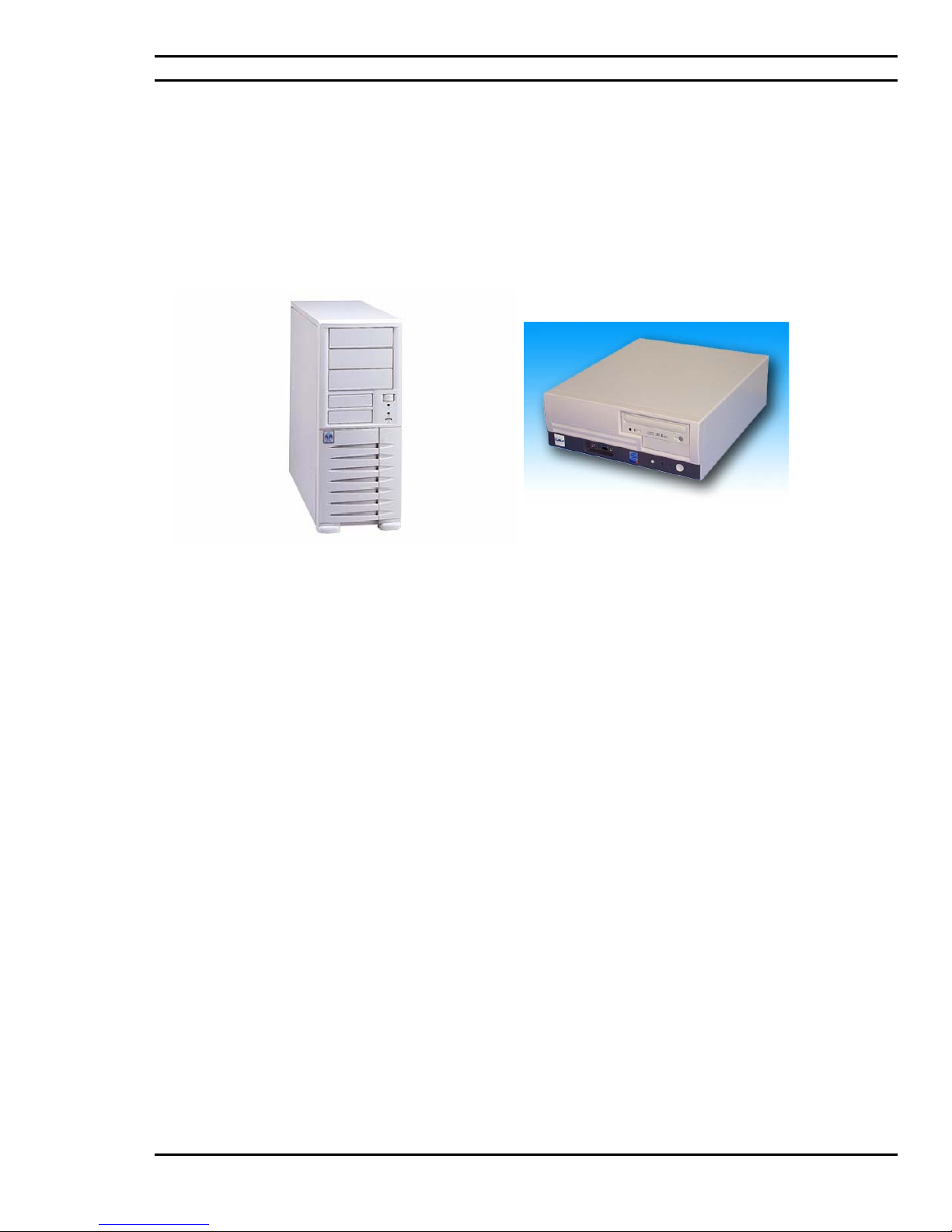
While supplied as standard in a mini tower case, Ciara Technologies Inc. can supply the Ciara Enterprise/Discovery
945GTP in a full range of cases that include smaller desktop ones as well as larger towers that are suitable for
applications that require a greater expansion capacity.
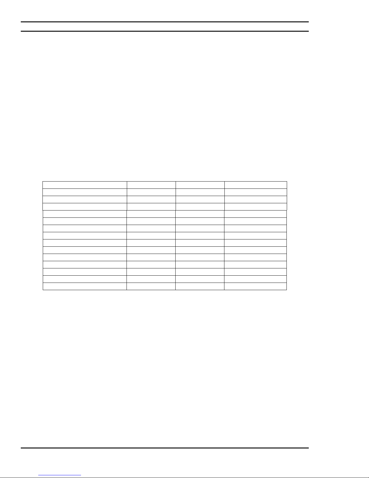
The Ciara Enterprise/Discovery 945GTP computer version is determined by the particular CPU installed and
currently the following versions are offered. These are:
Celeron D 256 KB 533 MHz 2,53 GHz
Celeron D 256 KB 533 MHz 2,66 GHz
Celeron D 256 KB 533 MHz 2,8 GHz
Celeron D 256 KB 533 MHz 2,93 GHz
Celeron D 256 KB 533 MHz 3,06 GHz
Celeron D 256 KB 533 MHz 3,2 GHz
Pentium 4 1 MB 800 MHz 2,8 GHz
Pentium 4 1 or 2 MB 800 MHz 3,0 GHz
Pentium 4 1 or 2 MB 800 MHz 3,2 GHz
Pentium 4 1 or 2 MB 800 MHz 3,4 GHz
Pentium 4 1 or 2 MB 800 MHz 3,6 GHz
Pentium 4 1 or 2 MB 800 MHz 3,8 GHz
Pentium D 2 x1 MB 800 MHz 2,8 GHz
Pentium D 2 x1 MB 800 MHz 3,0 GHz
Pentium D 2 x1 MB 800 MHz 3,2 GHz
Figure 1.1: CPU support list for Ciara Enterprise/Discovery 945GTP Computers
All versions utilize essentially the same Set-Up and configuration procedures and the same Intel/AMI BIOS.
Make a note that your new Ciara Enterprise/Discovery 945GTP computer supports the Intel Pentium 4 HyperThreading (HT) technology enabling the motherboard to see two logical processing units although only one is
installed. This technology was for a while reserved for Intel server motherboards and has now been implemented in
Intel desktop motherboards. This enhancement will allow considerably more data to be treated for a same CPU
cycle.
With care and proper operating procedure, all Ciara Enterprise/Discovery 945GTP computers will give many years
of trouble-free service. The Ciara Enterprise/Discovery 945GTP can be configured for a wide range of special
purpose, business, industrial and scientific applications.
The information provided in this guide is all
945GTP computer. We offer Technical Reference Manuals for sale to knowledgeable users.
that you should need to set up and use your Ciara Enterprise/Discovery
- 14 -
Page 15
Ciara Enterprise/Discovery 945GTP
Please note that any modifications or additions not made by Ciara Technologies Inc. or our authorized
personnel, to any Ciara Enterprise/Discovery 945GTP that is under Warranty, such as your insertion or
removal of adapter cards not supplied and installed by Ciara Technologies Inc. could cause damage and may
void the Warranty.
Please do not experiment if you are unsure, and remember we are ready to answer your questions. Please call
us first.
Figure 1.2: Ciara Enterprise / Discovery 945GTP in Mini-Tower (Enterprise) or desktop (Discovery) case
- 15 -
Page 16
Ciara Enterprise/Discovery 945GTP
Processor:
Bus:
System Board:
Intel Pentium® D (2.8 GHz to 3.2 GHz),
Intel Pentium
®
4 (2.8 GHz to 3.8 GHz) and
Celeron (2.53 to 3.2 GHz)
with LGA775 connector.
Front side bus: 533, 800 or 1066 MHz.
One PCI Express x16 video slot, one PCI Express x1 expansion slot
and two conventional PCI slots.
Intel D945GTP µATX format main board uses Intel 945G chipset
BIOS:
RAM:
Ports:
Drives:
Video:
Audio:
Network:
Certification:
Intel/AMI Flash BIOS standard, with ACPI, APM, DMI, Energy Star,
Plug & Play and SMBIOS features.
DDR2 240 pin Type PC400, PC533 or PC667 SDRAM, minimum
128MB and 4GB maximum. Four DIMM sockets. SPD (Serial
Presence Detect) memory is mandatory. Non-ECC memory only is
supported.
One 9-pin serial port, one 25-pin Parallel port, PS/2 style mouse and
keyboard ports, video port, four USB 2.0 ports, audio ports, RJ45
port.
3.5” 1.44 MB floppy drive, vast choice of EIDE CD-ROM drives and
vast choice of IDE Parallel ATA and Serial ATA hard disk drives.
The IDE controllers support two IDE devices at Ultra DMA
33/66/100.
Four Serial ATA controllers (3 Gbps) supporting one drive each.
Integrated Intel 82945G GMA950 video controller with 3-D
architecture, 32 bits per pixel graphics engine, 2-D acceleration, video
acceleration, MPEG 2 acceleration. DVMT technology enabling the
controller to use up to 224 MB of system memory. Two multiplexed
DVO port interfaces with 200 MHz pixel clocks using an ADD2 card
in the PCI Express x16 video slot.
Integrated Intel High Definition Audio 6 (Sigmatel 9220 audio codec)
sound controller with audio in, audio out and microphone.
Integrated Intel 82562EZ Fast Ethernet network interface controller
10/100Mbits with WOL or Marvell Yukon 88E50 Gigabit
10/100/1000 Mbits with WOL.
UL (E204926), FCC Class B, Microsoft (Windows 2000 and
Windows XP) certified, compliant with Energy Star guidelines for
energy efficiency.
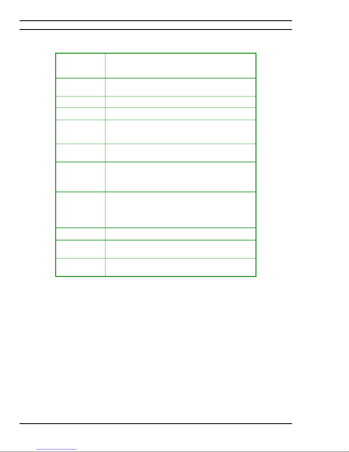
Figure 1.3: Standard Features of Ciara Enterprise/Discovery 945GTP Computers
- 16 -
Page 17
Ciara Enterprise/Discovery 945GTP
1.1: Upgrading
As the purchaser of a powerful state of the art Ciara Enterprise/Discovery 945GTP computer you have no doubt
decided on the features and upgrade capabilities that you might wish to add to your computer. There are many
exciting possibilities for upgrading your Ciara Enterprise/Discovery 945GTP. Ciara Technologies Inc. has
extensively tested a range of potential upgrade and enhancement options that range from hard disks to various
optical drives. Some of these work much better than others and we are able to recommend the ones that work best
with your Ciara Enterprise/Discovery 945GTP computer.
Ciara Technologies Inc. will be pleased to help you to ensure that you choose the most reliable and compatible system
components when the time comes to upgrade and enhance your Ciara Enterprise/Discovery 945GTP computer in a
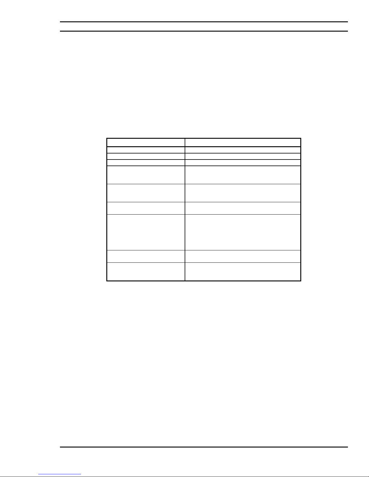
manner that will preserve the Warranty. Figure 1.4 summarizes the general features of the various types of upgrades
and enhancements that may be added to any Ciara Enterprise/Discovery 945GTP.
UPGRADES AVAILABLE Ciara Enterprise/Discovery 945GTP
Parallel ATA Hard Disk Drives Several hard disks ranging from 40 to 400 GB
Serial ATA Hard Disk Drives Several hard disks ranging from 40 to 400 GB
SCSI Hard Disk Drives Several hard disks ranging from 18 to 300 GB
Optical Drives Internal & external CD-ROMs, DVD-ROM’s,
PCI Express x16 Video
Controller
System Memory Up to 4 GB DDR2, 240 pin, PC400, PC533 or
Disk Controllers A PCI bus Parallel ATA IDE controller is built
Hi Res. Monitors & Display
Adapters
Network Adapters Several PCI or PCI Express x1 bus network
and writeable CD and DVD drives may be
added.
All video controllers compliant with the PCI
Express x16 standard, with 128 MB of video
memory or more.
PC667.
into the system as well as four Serial ATA
controllers (3 Gbps).
Optional SATA RAID (0, 1, 0+1 and 5)
PCI bus Ultra320 SCSI controller options are
available.
17 to 21 inches CRT or LCD monitors.
adapter cards for Ethernet and Token Ring
transmission media are available.
Figure 1.4: Upgrades for Ciara Enterprise/Discovery 945GTP Computers
1.2: Networking
Among the more exciting applications for extending the power and utility of Ciara Enterprise/Discovery 945GTP
computers is to connect them (using communication links and adapter cards) with other computer systems to form
computer / communication networks in order that software resources (such as databases) and hardware resources
(such as printers and modems) may be shared. This is referred to as Local Area Networking (LAN) and Wide Area
Networking (WAN).
All Ciara Enterprise/Discovery 945GTP computers can be networked using a wide variety of network adapters that
permit the Ciara Enterprise/Discovery 945GTP computer to operate with a full range of mini and mainframe
computers. For example the Ciara Enterprise/Discovery 945GTP can be networked using a wide variety of Ethernet
adapter cards while running the UNIX Operating System.
Ciara Technologies Inc.’s System Integration and Networks Group would be pleased to provide you with turnkey
solutions for all your Windows 2000 Server, Windows 2003 Server, Novell NetWare and SCO/UNIX networking
needs. We have trained and certified experts on staff to help you.
- 17 -
Page 18

Ciara Enterprise/Discovery 945GTP
2.0: The Ciara Enterprise/Discovery 945GTP BIOS
2.1: BIOS Configuration and Installation
The purpose of this section is to describe the procedures to set up the BIOS configuration options of your Ciara
Enterprise/Discovery 945GTP computer. All this work is done for you at the Ciara plant enabling the system to be
ready to start on Power on. However, we are describing this procedure as a means of transparency.
Every Ciara Enterprise/Discovery 945GTP is now supplied with the latest version of the Intel/AMI BIOS. The
Intel/AMI BIOS is a set of permanently recorded software that give the Ciara Enterprise/Discovery 945GTP its
fundamental operational characteristics.
The Intel/AMI BIOS is made up of code that provides the device-level control for the major I/O devices in the Ciara
Enterprise/Discovery 945GTP computer system. It contains a set of routines (called POST, for Power-On Self-Test)
that check out your Ciara Enterprise/Discovery 945GTP system when you turn it on.
The Intel/AMI BIOS name will be displayed on the screen of the monitor every time the power is turned on.
The Set-Up procedure involves storing in the Ciara Enterprise/Discovery 945GTP computer data & hardware
information (called configuration information) including:
• Date & time,
• Type(s) of floppy disk drive(s),
• Type(s) of hard disk drive(s),
• Type of display adapter,
• Presence or absence of a keyboard,
It will be necessary to run the Set-Up program if you do any of the following:
• Replace the battery,
• Install a second hard drive or replace the one you have with a new model,
• You have not used your system for a considerable period,
• The original set-up has been "lost".
In any of these cases you must use the Set-Up
actually installed in your system.
To use the
Set-Up program proceed as follows:
1. Turn on or re-boot (press simultaneously <CTRL>, <ALT>, <DEL>) your Ciara
Enterprise/Discovery 945GTP system. After the Intel/AMI BIOS performs a series of
diagnostic checks, the following message appears:
RESS <F2> to enter Set-Up.
P
2. Press the <F2> key to enter the Intel/AMI BIOS Set-Up program.
3. Choose a
Set-Up option with the arrow keys and press < ↵ > to select.
program to modify the system parameters to reflect the options
- 18 -
Page 19
Ciara Enterprise/Discovery 945GTP
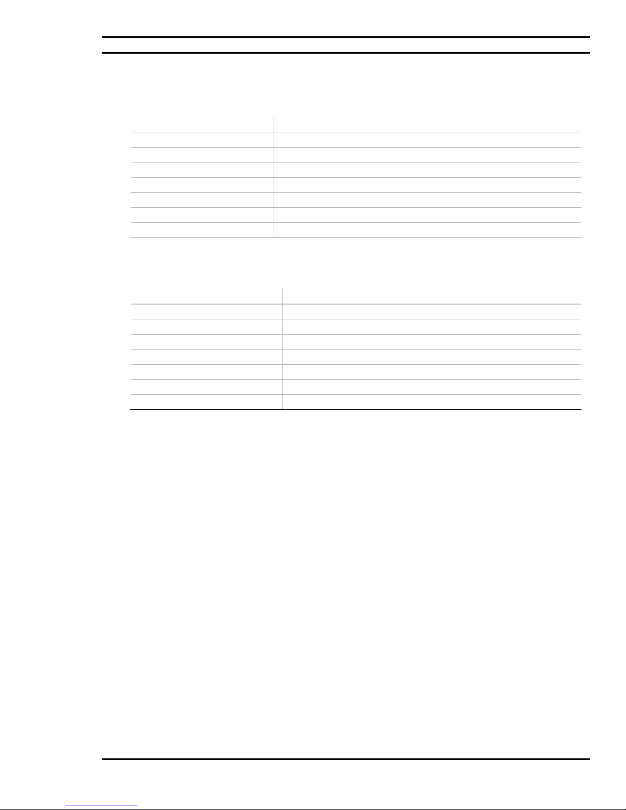
2.2: BIOS Set-up Program Menu Bar
Function Description
Maintenance Clears passwords and displays processor information.
Main Displays processor and memory information.
Advanced Configures advanced features available through the chipset.
Security Sets passwords and security features.
Power Configures power management features and power supply controls.
Boot Selects boot options.
Exit Saves or discards changes to Set-up program options.
2.3: BIOS Set-up Program Function Keys
BIOS Set-up Program Function Key Description
<←> or <→> Selects a different menu screen (Moves the cursor left or right).
<↑> or <↓> Selects an item (Moves the cursor up or down).
<Tab> Selects a field (Not implemented)
<Enter> Executes command or selects the submenu.
<F9> Loads the default configuration values for the current menu.
<F10> Saves the current values and exits the BIOS Set-up program.
<Esc> Exits the menu.
2.4: PCI Autoconfiguration
The BIOS can automatically configure PCI devices. PCI devices may be onboard or add-in cards.
Autoconfiguration lets a user insert or remove PCI cards without having to configure the system. When a user
turns on the system after adding a PCI card, the BIOS automatically configures interrupts, the I/O space, and other
system resources. Any interrupts set to Available in Setup are considered to be available for use by the add-in card.
2.5: PCI IDE Support
If you select Auto in the BIOS Setup program, the BIOS automatically sets up the PCI IDE connector with
independent I/O channel support. The IDE interface supports hard drives up to ATA-66/100 and recognizes any
ATAPI compliant devices, including CD-ROM drives, tape drives, and Ultra DMA drives. The BIOS determines the
capabilities of each drive and configures them to optimize capacity and performance. To take advantage of the high
capacities typically available today, hard drives are automatically configured for Logical Block Addressing (LBA) and
to PIO Mode 3 or 4, depending on the capability of the drive. You can override the autoconfiguration options by
specifying manual configuration in the BIOS Setup program.
To use ATA-66/100 features, the following items are required:
• An ATA-66/100 peripheral device
• An ATA-66/100 compatible cable
• ATA-66/100 operating system device drivers
NOTE
Do not connect an ATA device as a slave on the same IDE cable as an ATAPI master device. For example, do not
connect an ATA hard drive as a slave to an ATAPI CD-ROM drive.
- 19 -
Page 20

Ciara Enterprise/Discovery 945GTP
2.6: System Management BIOS (SMBIOS)
SMBIOS is a Desktop Management Interface (DMI) compliant method for managing computers in a managed
network.
The main component of SMBIOS is the Management Information Format (MIF) database, which contains information
about the computing system and its components. Using SMBIOS, a system administrator can obtain the system types,
capabilities, operational status, and installation dates for system components. The MIF database defines the data and
provides the method for accessing this information. The BIOS enables applications such as third-party management
software to use SMBIOS. The BIOS stores and reports the following SMBIOS information:
• BIOS data, such as the BIOS revision level
• Fixed-system data, such as peripherals, serial numbers, and asset tags
• Resource data, such as memory size, cache size, and processor speed
• Dynamic data, such as event detection and error logging
Non-Plug and Play operating systems, such as Windows NT*, require an additional interface for obtaining the
SMBIOS information. The BIOS supports an SMBIOS table interface for such operating systems. Using this support,
an SMBIOS service-level application running on a non-Plug and Play operating system can obtain the SMBIOS
information.
2.7: Legacy USB Support
Legacy USB support enables USB devices to be used even when the operating system’s USB drivers are not yet
available. Legacy USB support is used to access the BIOS Setup program, and to install an operating system that
supports USB. By default, Legacy USB support is set to Enabled.
Legacy USB support operates as follows:
1. When you apply power to the computer, legacy support is disabled.
2. POST begins.
3. Legacy USB support is enabled by the BIOS allowing you to use a USB keyboard to enter and configure the BIOS
Setup program and the maintenance menu.
4. POST completes.
5. The operating system loads. While the operating system is loading, USB keyboards and mice are recognized and
may be used to configure the operating system. (Keyboards and mice are not recognized during this period if
Legacy USB support was set to Disabled in the BIOS Setup program.)
6. After the operating system loads the USB drivers, all legacy and non-legacy USB devices are recognized by the
operating system, and Legacy USB support from the BIOS is no longer used.
To install an operating system that supports USB, verify that Legacy USB support in the BIOS Setup program is set to
Enabled and follow the operating system’s installation instructions.
- 20 -
Page 21

Ciara Enterprise/Discovery 945GTP
2.8: BIOS Updates
The BIOS can be updated using either of the following utilities, which are available on the Intel World Wide Web
site:
• Intel® Express BIOS Update utility, which enables automated updating while in the Windows environment. Using
this utility, the BIOS can be updated from a file on a hard disk, a 1.44 MB diskette, or a CD-ROM, or from the file
location on the Web.
• Intel® Flash Memory Update Utility, which requires creation of a boot diskette and manual rebooting of the system.
Using this utility, the BIOS can be updated from a file on a 1.44 MB diskette (from a legacy diskette drive or an LS120 diskette drive) or a CD-ROM.
Both utilities verify that the updated BIOS matches the target system to prevent accidentally installing an
incompatible BIOS.
NOTE
Review the instructions distributed with the upgrade utility before attempting a BIOS upda te.
2.8.1 Language Support
The BIOS Setup program and help messages are supported in US English. Additional languages are available
in the Integrator’s Toolkit utility. Check the Intel website for details.
2.8.2 Custom Splash Screen
During POST, an Intel® splash screen is displayed by default. This splash screen can be augmented with a
custom splash screen. The Integrator’s Toolkit that is available from Intel can be used to create a custom
splash screen.
NOTE
If you add a custom splash screen, it will share space with the Intel branded logo.
- 21 -
Page 22
Ciara Enterprise/Discovery 945GTP
2.9: Boot Options
In the BIOS Setup program, the user can choose to boot from a diskette drive, hard drives, CD-ROM, or the network.
The default setting is for the diskette drive to be the first boot device, the hard drive second, and the ATAPI CD-ROM
third. The fourth device is disabled.
2.9.1 CD-ROM Boot
Booting from CD-ROM is supported in compliance to the El Torito bootable CD-ROM format specification.
Under the Boot menu in the BIOS Setup program, ATAPI CD-ROM is listed as a boot device. Boot devices
are defined in priority order. Accordingly, if there is not a bootable CD in the CD-ROM drive, the system
will attempt to boot from the next defined drive.
2.9.2 Network Boot
The network can be selected as a boot device. This selection allows booting from the onboard LAN or a
network add-in card with a remote boot ROM installed. Pressing the <F12> key during POST automatically
forces booting from the LAN. To use this key during POST, the User Access Level in the BIOS Setup
program's Security menu must be set to Full.
2.9.3 Booting with attached devices
For use in embedded applications, the BIOS has been designed so that after passing the POST, the operating
system loader is invoked even if the following devices are not present:
• Video adapter
• Keyboard
• Mouse
2.9.4 Changing the Default Boot Device During POST
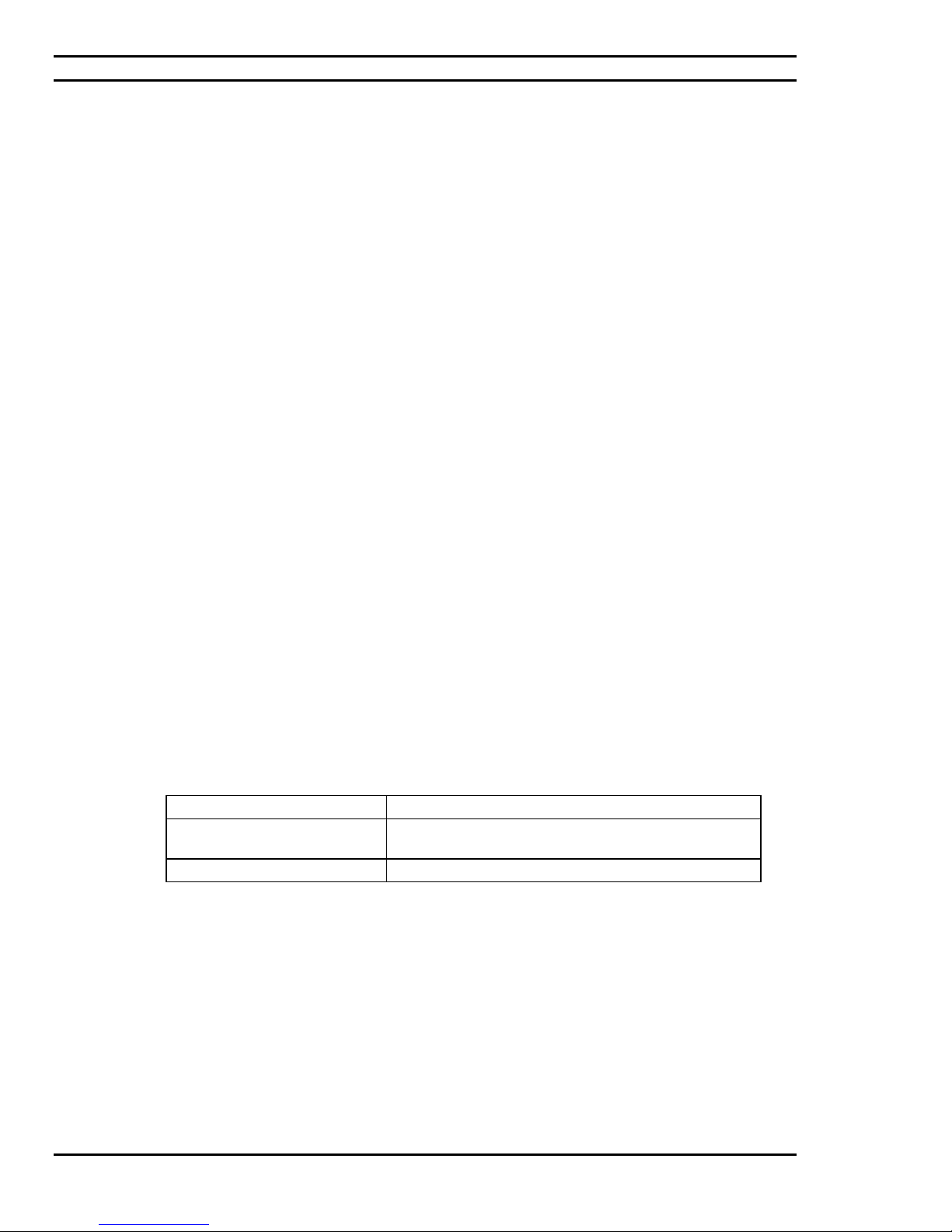
Pressing the <F10> key during POST causes a boot device menu to be displayed. This menu displays the list
of available boot devices (as set in the BIOS setup program’s Boot Device Priority Submenu). The below
table lists the boot device menu options.
Boot Device Menu Function
Keys
<↑> ou <↓>
< ↵ > Exits the menu, saves changes, and boots from the
<Esc>
Description
Selects a default boot device.
selected device.
Exits the menu without saving changes.
- 22 -
Page 23

Ciara Enterprise/Discovery 945GTP
2.10: Fast Booting Systems with Intel Rapid BIOS Boot
These factors affect system boot speed:
• Selecting and configuring peripherals properly
• Using an optimized BIOS, such as the Intel® Rapid BIOS
.
2.10.1 Peripheral Selection and Configuration
The following techniques help improve system boot speed:
• Choose a hard drive with parameters such as “power-up to data ready” less than eight seconds, that
minimize hard drive start-up delays.
• Select a CD-ROM drive with a fast initialization rate. This rate can influence POST execution time.
• Eliminate unnecessary add-in adapter features, such as logo displays, screen repaints, or mode changes in
POST. These features may add time to the boot process.
• Try different monitors. Some monitors initialize and communicate with the BIOS more quickly, which
enables the system to boot more quickly.
2.10.2 Intel Rapid BIOS Boot
Use of the following BIOS Setup program settings reduces the POST execution time.
In the Boot Menu:
• Set the hard disk drive as the first boot device. As a result, the POST does not first seek a diskette drive,
which saves about one second from the POST execution time.
• Disable Quiet Boot, which eliminates display of the logo splash screen. This could save several seconds of
painting complex graphic images and changing video modes.
• Enable Intel Rapid BIOS Boot. This feature bypasses memory count and the search for a diskette drive.
In the Peripheral Configuration submenu, disable the LAN device if it will not be used. This can reduce up to
four seconds of option ROM boot time.
NOTE
It is possible to optimize the boot process to the point where the system boots so quickly that the
Intel logo screen (or a custom logo splash screen) will not be seen. Monitors and hard disk drives
with minimum initialization times can also contribute to a boot time that might be so fast that
necessary logo screens and POST messages cannot be seen.
This boot time may be so fast that some drives might be not be initialized at all. If this condition
should occur, it is possible to introduce a programmable delay ranging from three to 30 seconds
(using the Hard Disk Pre-Delay feature of the Advanced Menu in the Drive Configuration
Submenu of the BIOS Setup program).
- 23 -
Page 24
Ciara Enterprise/Discovery 945GTP
2.11: BIOS Security Features
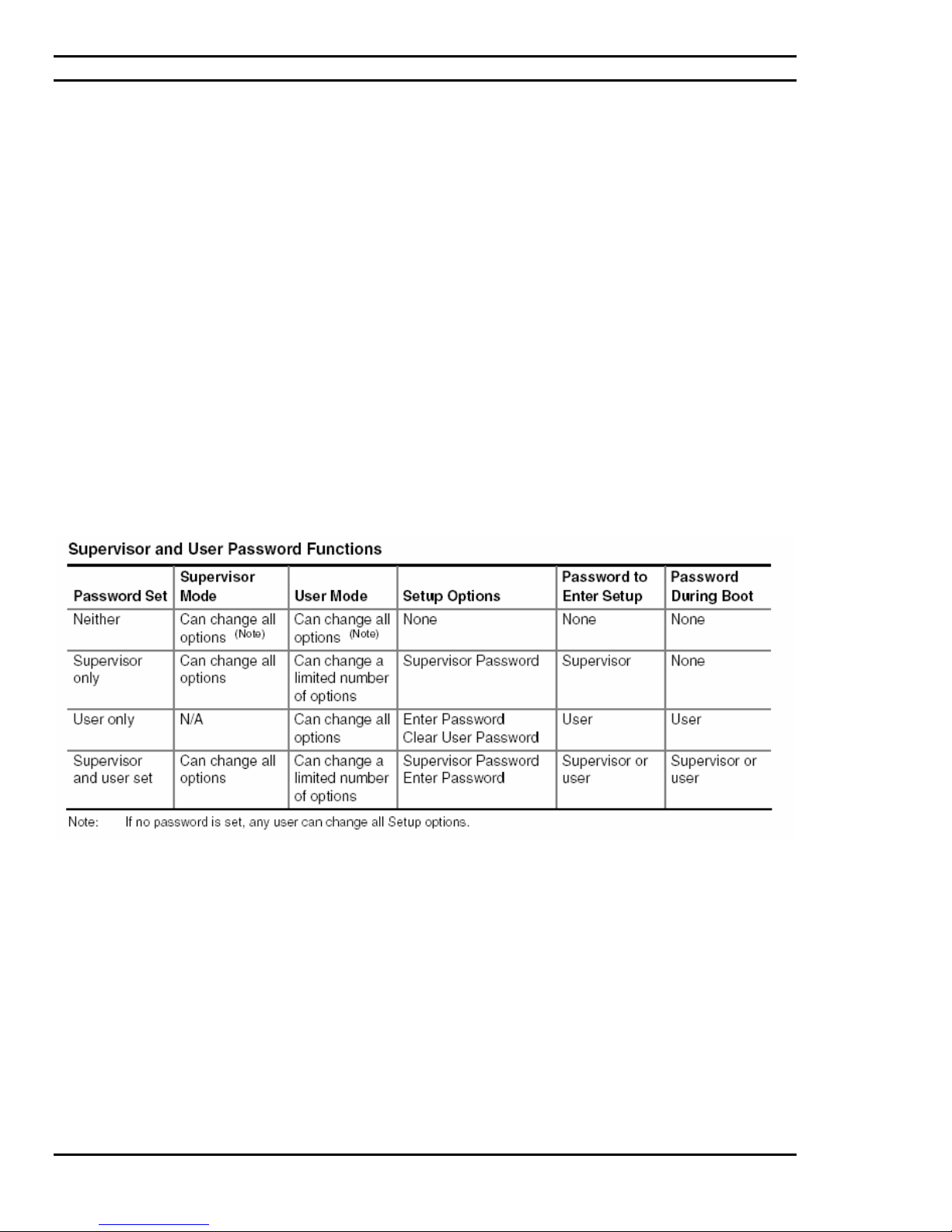
The BIOS includes security features that restrict access to the BIOS Setup program and who can boot the computer. A
supervisor password and a user password can be set for the BIOS Setup program and for booting the computer, with
the following restrictions:
• The supervisor password gives unrestricted access to view and change all the Setup options in the BIOS Setup
program. This is the supervisor mode.
• The user password gives restricted access to view and change Setup options in the BIOS Setup program. This is the
user mode.
• If only the supervisor password is set, pressing the <Enter> key at the password prompt of the BIOS Setup program
allows the user restricted access to Setup.
• If both the supervisor and user passwords are set, users can enter either the supervisor password or the user password
to access Setup. Users have access to Setup respective to which password is entered.
• Setting the user password restricts who can boot the computer. The password prompt will be displayed before the
computer is booted. If only the supervisor password is set, the computer boots without asking for a password. If both
passwords are set, the user can enter either password to boot the computer.
• For enhanced security, use different passwords for the supervisor and user passwords.
• Valid password characters are A-Z, a-z, and 0-9. Passwords may be up to 16 characters in length.
The below table shows the effects of setting the supervisor password and user password. This table is for reference
only and is not displayed on the screen.
- 24 -
Page 25
Ciara Enterprise/Discovery 945GTP
3.0: Ciara Enterprise/Discovery 945GTP specifications
In the following sections the specifications of the Ciara Enterprise/Discovery 945GTP models are detailed, and the
layout and configuration of their motherboard are illustrated.
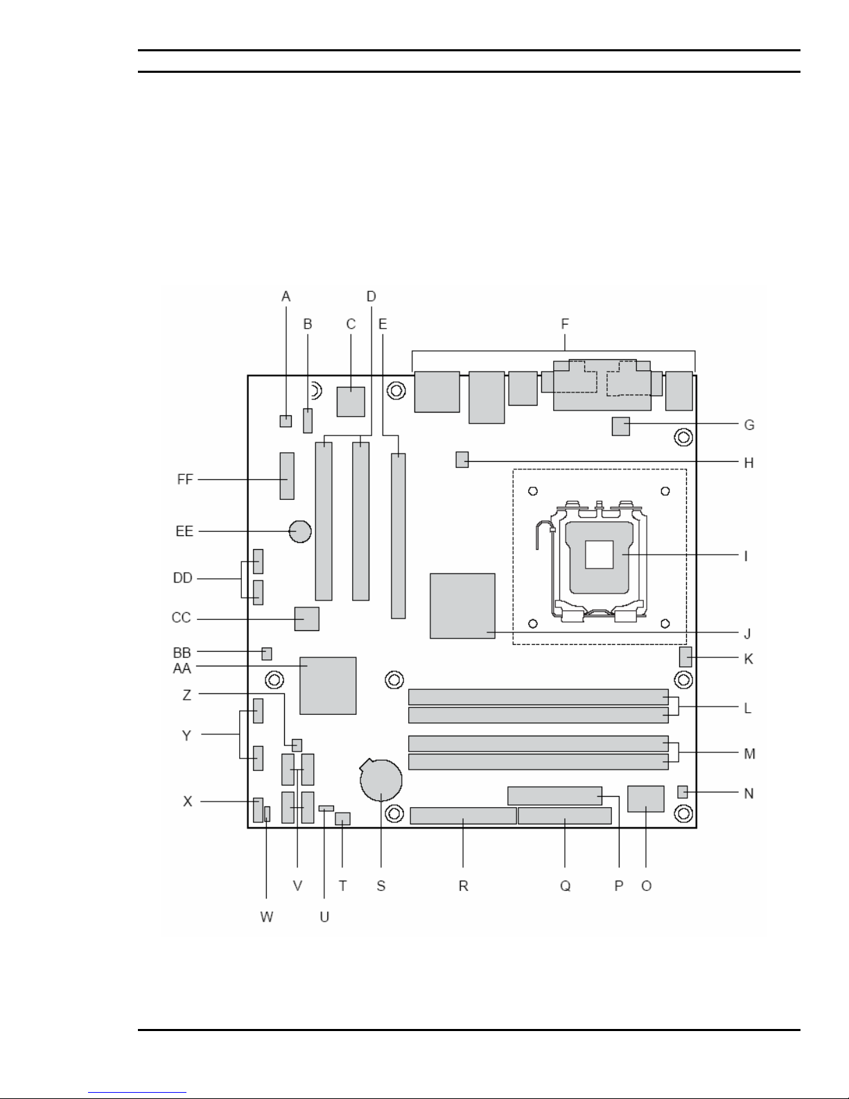
3.1: Configuration & Layout - Ciara Enterprise/Discovery 945GTP Main
board
The layout of the motherboard that Ciara Technologies Inc. uses in its Ciara Enterprise/Discovery 945GTP systems
is shown in Figure 3.1
Figure 3.1: Layout of Ciara Enterprise/Discovery 945GTP Mainboard
- 25 -
Page 26
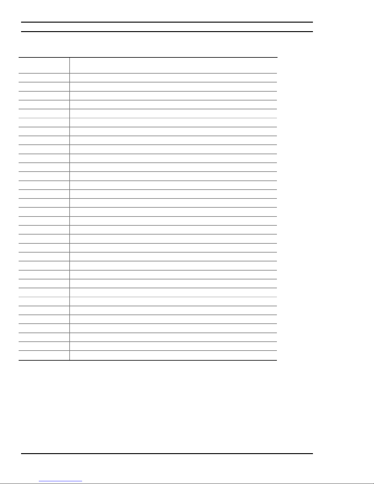
Item/callout from
Figure 3.1
A Audio codec
B Front panel audio connector
C Ethernet device
D PCI Conventional bus add-in card connectors [2]
E PCI Express x16 bus a dd-in card connector
F Back panel connectors
G +12V power connector (ATX12V)
H Rear chassis fan connector
I LGA775 processor socket
J Intel 82945G GMCH
K Processor fan conn ector
L DIMM Channel A sockets [2]
M DIMM Channel B sockets [2]
N SCSI LED connector (optional)
O Legacy I/O controller
P Power connector
Q Diskette drive connector
R Parallel ATE IDE connector
S Battery
T Front chassis fan connector
U BIOS Setup configuration jumper block
V Serial ATA connectors [4]
W Auxiliary front panel power LED connector
X Fr ont panel connector
Y Front panel USB connectors [2]
Z Chassis intrusion connector
AA Intel 82801G I/O Controller Hub (ICH7)
BB SPI flash device
CC IEEE-1394a controller (optional)
DD Front panel IEEE-1394a connectors (optional) [2]
EE Speaker
FF PCI Express x1 bus add-in card connector
Ciara Enterprise/Discovery 945GTP
Board Components Shown in Figure 3.1
Description
- 26 -
Page 27
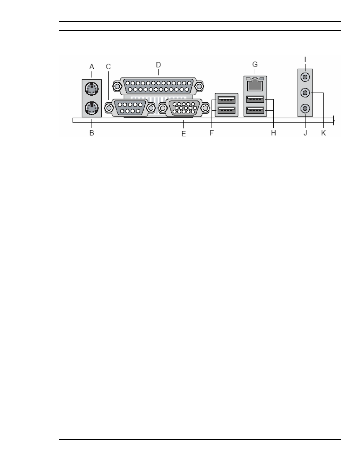
Back Panel Connectors
Ciara Enterprise/Discovery 945GTP
Description
A PS/2 mouse port [Green]
B PS/2 keyboard port [Purple]
C Serial port A [Teal]
D Parallel port [Burgundy]
E VGA port
F USB ports (two)
G LAN
H USB ports (two)
I Audio line in/Retasking Jack [Blue]
J Mic in/Retasking Jack [Pink]
K Front left/right channel audio out/Two channel audio line out/Retasking Jack [Lime green]
Figure 3.2: Back Panel Connectors
- 27 -
Page 28
Ciara Enterprise/Discovery 945GTP
3.2: The PCI Express Bus
The PCI Express bus was developed to accelerate communication between the various components of the
motherboard and to accelerate data transfer between add in cards and the system. The PCI Express x1 add in cards
transfer date at the rate of 500 Mb/second, four times faster than the conventional PCI bus. The video cards that
equip this system must be PCI Express x16 type. These cards enable a transfer rate of 8 Gbit/second, two times
faster that its predecessor the AGP 8x video card.
3.3: Disk Drives
Floppy Drives
Your Ciara Enterprise/Discovery 945GTP computer system is configured with a 3.5” floppy disk drive, which has a
1.44 MB capacity. Optionally, a 3.5” diskette drive with a 2.88 MB capacity may be ordered.
Hard Disk Drives
Your new Ciara Enterprise/Discovery 945GTP computer system may be equipped with an EIDE Parallel ATA hard
drive that will transfer data at the speed of 100 megabytes per second. Note that your Ciara Enterprise/Discovery
945GTP supports the use of up to two Enhanced Integral Drive Electronics (EIDE) peripherals. Typically this might
include one hard disk drive and a CD-ROM drive or DVD-ROM drive.
However, you may also choose the Serial ATA technology for your hard drive since the Ciara
Enterprise/Discovery 945GTP system has four Serial ATA controllers supporting one drive each. Serial ATA
hard drives transfer data at the speed of 3 gigabytes per second.
CD-ROM Drives
The Ciara Enterprise/Discovery 945GTP model may be supplied with an EIDE CD-ROM drive. The CD-ROM
drive is a half-height 5-¼ inch wide storage device, capable of holding about 650 Mbytes of data. Optionally, your
system may be equipped with a DVD-ROM drive, a CD-Writer drive, a combo DVD/CDRW drive or a DVD writer.
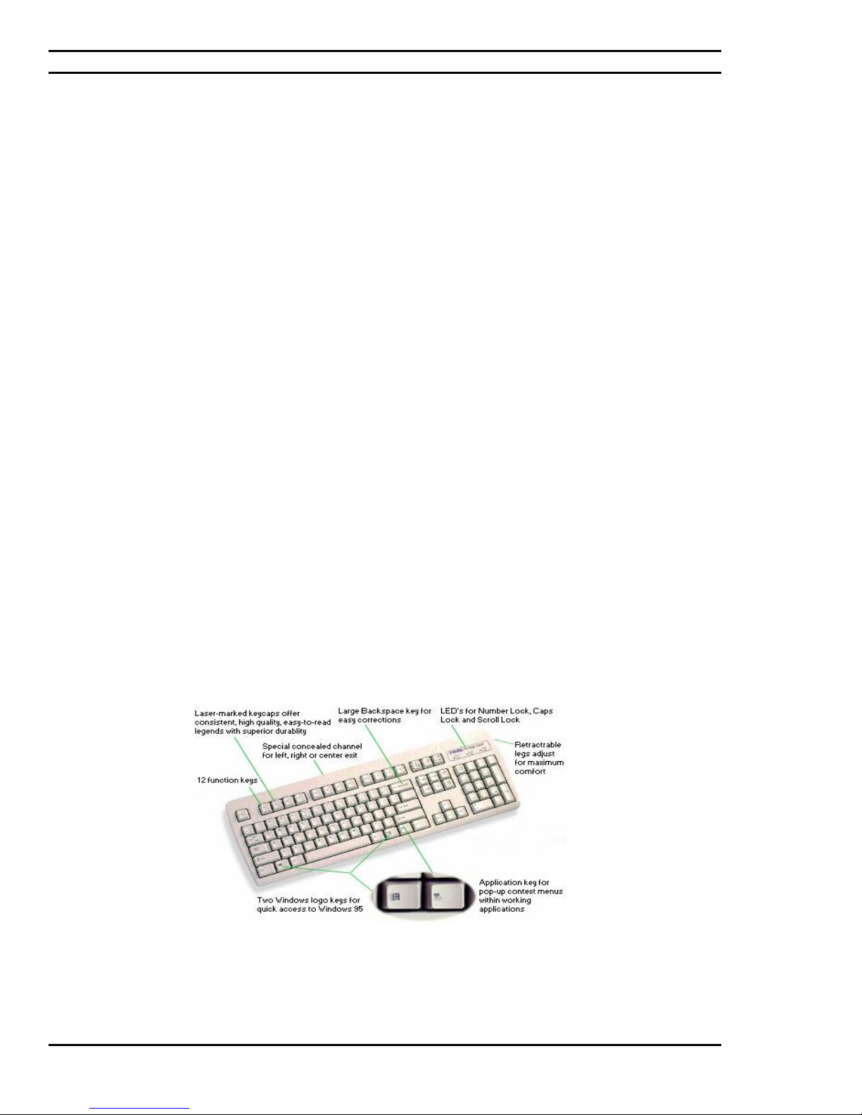
3.4: Keyboard
Your keyboard has a set of function keys, cursor keys and a numeric keypad. The figure below shows a typical
keyboard. Under the rear of the keyboard are two small legs that can be pulled out or pushed in to change the
keyboard angles.
Figure 3.3: Typical keyboard layout
- 28 -
Page 29

Ciara Enterprise/Discovery 945GTP
3.5: Intel GMA950 Video Set-up
Your Ciara Enterprise / Discovery 945GTP Series computer system is delivered with an integrated Intel GMA950
video controller for which the chipset parameters have been optimized according to the monitor you have chosen
with your system. The mere fact of inserting a video card in the PCI Express x16 slot will deactivate the onboard
controller.
The integrated controller includes the Intel 82945G Graphics/memory controller, which has a 32 bpp (bits per pixel)
graphics engine, a 333 MHz core frequency, a 256-bit internal data path for 2-D and 32-bit for 3-D graphics, motion
video acceleration, Pixel Shader 2.0 software, 4-pixel pipes and Vertex Shader software. The controller has an
integrated 24-bit 400 MHz RAMDAC engine for display with a DDC2B compliant interface.
controller supports dual monitor synchronous display and hardware motion compensation for software MPEG2
decode.
Optionally, the x16 PCI Express slot may be equipped with an ADD2 (Advanced Digital Display) card offering two
multiplexed DVO port interfaces with 200 MHz pixel clocks. If you choose to add the ADD2 card, you can no longer
add an PCI Express x16 video controller since the ADD2 card occupies the PCI Express x16 video slot.
The Intel 82945G video controller uses dynamically the system memory for its needs. It needs a fixed portion of the
memory for itself and will allow dynamically the rest. The GMA950 controller will use up to 128 Mb of RAM if the
system is equipped with more than 256 MB of memory but less than 512 Mb. The GMA950 controller will use up to
224 Mb of RAM if the system is equipped with more than 512 MB of memory is installed. The minimum amount and
maximum amount of memory used by the GMA950 controller are defined in the BIOS. We recommend you install a
minimum of 512 MB of memory if you have chosen this video controller as a base peripheral.
If you wish to reinstall or modify the configuration of the system video controller to optimize it to a new monitor,
you will need to use the video utility and driver software provided with your system. Similarly, if you need to reinstall the system software on your system at any time, you will need the video utility and driver software.
In video mode, the
Installing Utility and Driver Software
All drivers and utility software have been installed in your system at the Ciara Technologies facilities. You will find
them in a folder named “C\BACKUP”on the C: drive of your system. We strongly recommend that you copy the
content on floppies in case you need to reinstall. For technical assistance in case of accidental data loss, please
contact our service department at 1-877-242-7272 for help in the reinstallation of your drivers.
DPMS Settings
Your system has been configured so that all aspects of video power management are controlled by the BIOS of your
computer system. Therefore it is neither necessary nor desirable to also set up any power management methods within
your operating system.
3.6: Audio Set-up
The Ciara Enterprise/Discovery 945GTP is manufactured with an integrated High Definition Audio Controller based
on the Sigmatel 9220 audio codec. In order to fully configure, or to re-configure, the audio software in your system,
you will need to use the audio utility and driver CD-ROM. For further details, please refer to the separate manual
provided with your system, which deals with your audio features, or to the online help text within the audio utility and
driver CD-ROM.
3.7: I/O Port Set-up
Each Ciara Enterprise/Discovery 945GTP computer system includes built-in multi-I/O capabilities. These provide
your computer with one high-speed serial port, PS/2 mouse port, PS/2 keyboard port, one parallel printer port, one
video port, one floppy controller, one Enhanced IDE Parallel ATA disk drive controller with one interface supporting
two IDE devices, four Serial ATA disk drive controllers (3 Gbps) supporting one drive each, four Universal Serial
Bus (USB 2.0) ports, audio ports and one Fast Ethernet RJ-45 port (Gigabit optional)
- 29 -
Page 30

Ciara Enterprise/Discovery 945GTP
To configure these I/O ports, or to disable them, use the BIOS configuration screens. Please refer to the paragraphs in
section 2.0, “BIOS Configuration and installation” for more information on this subject.
3.8: Intel® Active Management Technology (Optional)
NOTE: Intel Active Management Technology (AMT) is available only on boards that use the Intel
Ethernet Controller.
®
82573E
Intel Active Management Technology (AMT) offers IT organizations tamper-resistant and persistent management
capabilities. Specifically, Intel
management and remote diagnostics and/or recovery capabilities for networked platforms. With Intel AMT, IT
organizations can easily get accurate platform information, and can perform remote updating, diagnostics, debugging,
and repair of a system, regardless of the state of the operating system and the power state of the system. Intel AMT
enables IT organizations to discover, heal, and protect all of their computing assets, regardless of system state in the
manner described below.
• Discovering hardware and software computing assets:
o Intel AMT stores hardware and software asset information in non-volatile memory and allows IT to
read the asset information anytime, even if the PC is off
o Users cannot remove or prevent IT organization access to the information because it does not rely
on software agents
®
AMT is a hardware-based solution that offers encrypted and persistent asset
• Healing systems remotely, regardless of the operating system or system state:
o Intel AMT provides out-of-band diagnostics and recovery capabilities for IT organizations
to remotely diagnose and repair PCs after software, operating system, or hardware failures
o Alerting and event logging help IT organizations detect and diagnose problems quickly to
reduce end-user downtime
• Protecting the enterprise against malicious software attacks:
o Intel AMT helps IT organizations keep software versions and virus protection consistent
and up-to-date across the enterprise
o Version information is stored in non-volatile memory for access anytime by third party
software to check and, if necessary, wake a system to perform off-hours updates
The key features of Intel AMT include:
• Secure Out of Band (OOB) system management that allows remote management of PCs regardless
of system power or operating system state.
o SSL3.1/TLS encryption
o HTTP authentication
o TCP/IP
o HTTP web GUI
o XML/SOAP API
• Remote troubleshooting and recovery that can significantly reduce desk-side visits and potentially
increasing efficiency of IT technical staff.
o System event log
o IDE-Redirection or PXE boot; Network drive or remote CD boot
o Serial over LAN
o OOB diagnostics
o Remote control
o Remote BIOS update
• Proactive alerting that decreases downtime and minimizes time to repair.
o Programmable policies
o Operating system lock-up alert
o Boot failure alert
o Hardware failure alerts
- 30 -
Page 31

Ciara Enterprise/Discovery 945GTP
• Third party non-volatile storage that prevents users from removing critical inventory, remote
control, or virus protection agents.
o Nonvolatile storage for agents
o Tamper-resistant
• Remote hardware and software asset tracking that eliminates time-consuming manual inventory
tracking, which also reduces asset accounting costs.
o E-Asset Tag
o HW/SW inventory
- 31 -
Page 32
Ciara Enterprise/Discovery 945GTP
4.0: Installing and upgrading your system
4.1: Unpacking Your Computer
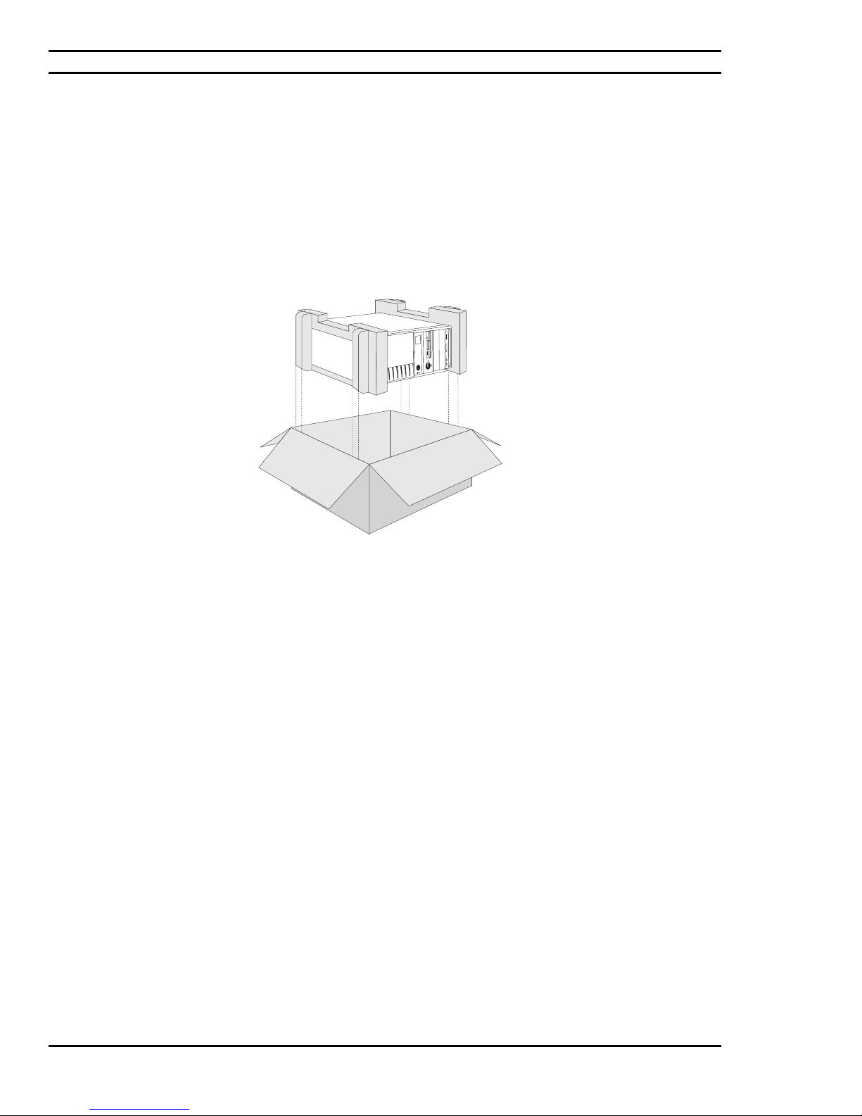
Your PC is packed with moulded foam on each end to keep it in place during transit.
Carefully unpack your computer and be sure to save all cartons and foam for future shipping and transportation.
To repack the PC it may be easier to place the moulded cushioning on the ends of the PC, and then slide the box
over the PC together with the cushioning, rather than lifting the PC.
Figure 4.1: Unpacking the System Unit
4.2: Choosing a Site for the System
All Ciara Technologies Inc. computers operate reliably in a typical office or home environment. Choose a location
that is readily accessible and:
• Is near a grounded, three pronged power outlet
• Is clean and dust free
• Is well-ventilated and lighted and away from sources of heat
• Is isolated from strong electromagnetic fields produced by electrical devices (such as air
conditioners, large fans, large electric motors, radio and TV transmitters, and amateur radio
transmitters).
• Has an appropriate table or desk that will allow you to work without physical discomfort
and strain.
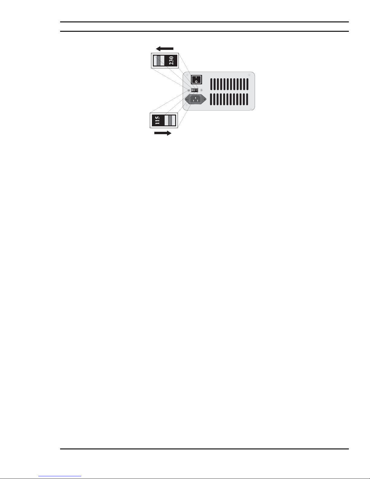
Next, inspect the rear of the Ciara Enterprise/Discovery 945GTP system Unit, to ensure that the power supply
voltage selector has been set for the correct voltage for your area. For example, in Canada and the U.S.A. the
selector should be set to 115 V. In Germany, Italy and the UK, the selector should be set to 230 V. If necessary, as
shown in Figure 4.2, a small screwdriver can be used to accomplish this. If you received your computer directly
from Ciara Technologies Inc. this power switch has already been correctly set.
- 32 -
Page 33
Ciara Enterprise/Discovery 945GTP
Figure 4.2: Setting the Voltage Selector
A few general precautions should always be observed. These are:
1) Never connect any peripheral such as a monitor, printer, modem, etc. to the system unit if the
power is turned "ON". Always turn the power switch to "OFF" first.
2) Never remove any internal adapter cards in the system unit if the power is turned "ON" as this
will ruin the Card/Computer and Void the Warranty
.
3) Never install and connect more peripherals than available power supply plugs to exceed the
maximum power of the system.
- 33 -
Page 34
Ciara Enterprise/Discovery 945GTP
4.3: Connecting I/O Devices
Unpack the monitor and all of its connecting cables. Place the monitor on the table as close as possible to the
computer. Connect the monitor signal and monitor power cable.
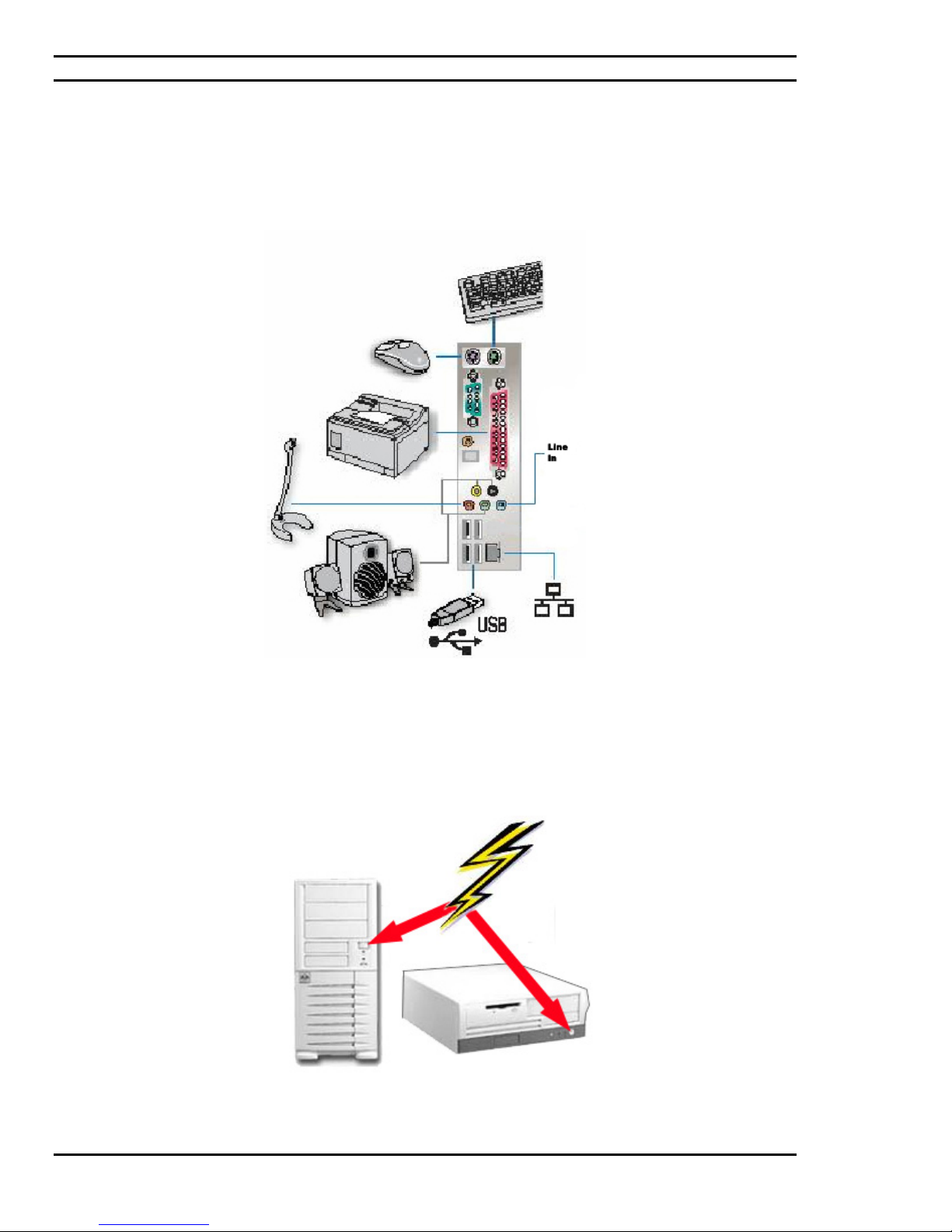
External USB, audio, PS2, serial and parallel port devices may be connected to the appropriate ports whose locations
are as illustrated in Figure 4.3.
Figure 4.3: Connecting the Peripherals.
NOTE: Some Monitor Power Cables may be plugged directly into the main power receptacle of your home or office.
Figure 4.4: Turning "ON" the Power Switch
- 34 -
Page 35

Ciara Enterprise/Discovery 945GTP
4.4: Installing Adapter Cards
Should it become necessary to install new batteries, an optional adapter, or such options as an internal modem, etc.
in the System Unit, we recommend consulting section 7 of this Guide.
NOTE: Ciara Technologies Inc. strongly advises that a grounded wrist strap be worn while carrying out the
installation and removal of adapter cards. Please also remember that any damage caused by improper handling and
static electricity will void your Warranty.
Ciara Technologies strongly recommends that such task be done by one of its authorized
service centre.
4.5: Replacing the System Batteries
In all Ciara Enterprise/Discovery 945GTP models the battery is a standard 3.3V Lithium battery model CR-2032.
This type of battery should last at least 3 years, if the system is not in use. If the system is continually in use, the
battery should last at least 7 years. If the battery wears out, your system will no longer retain BIOS information
when turned off. For example, you will get a message stating that the time and date is invalid. If this happens, you
should replace the battery, or call your Ciara Technologies Inc. service representative.
CAUTION:
There is a danger of explosion if the battery is incorrectly replaced. Replace only with the same type as recommended
by Ciara. The disposal of used batteries is subject to environment issues and we recommend that this work be done by
a qualified Ciara technician who will dispose safely of the used battery.
4.6: Installing an Upgrade CPU
All Ciara Enterprise/Discovery 945GTP models may be enhanced by the installation of a higher performing CPU.
Since this upgrade necessitates a lot of care and attention, it should be carried out by a Ciara Technologies Inc.
authorized service centre. Please take a note that the Ciara Enterprise/Discovery 945GTP models use exclusively
LGA775 processor technologies and are not compatible to other types of processors.
4.7: Installing an Upgrade Flash BIOS
You may obtain the latest BIOS revision for you Ciara Enterprise/Discovery 945GTP system on Ciara Technologies’
web site at
expand the downloaded file on the diskette.
To install a new flash BIOS, boot your system with the diskette containing the new BIOS revision and follow the on
screen instructions. The update will not take effect until after the system has been rebooted.
Before any new BIOS is programmed into the system, be very careful to ensure that the BIOS is intended for use with
your specific system board. If not, you may completely disable your system, and require Ciara Technologies Inc.
service assistance to restore the system to working order.
http://www.ciara-tech.com under “Support” “BIOS”. Once downloaded, create a bootable diskette and
- 35 -
Page 36
Ciara Enterprise/Discovery 945GTP
4.8: Installing DIMM Memory Modules
Increasing the amount of system memory is the most common "on-site" enhancement that is likely to be made to your
Ciara Enterprise/Discovery 945GTP computer. Increasing your computer’s memory usually involves adding main
memory. DDR2 Synchronous Dynamic Random Access Memory (DDR2 SDRAM) is packaged only in 240-pin Dual
In-Line Memory Modules 1.8 V (DIMMs).
Your Ciara Enterprise/Discovery 945GTP uses only DIMM memory modules. Each DIMM module can have a
capacity of 256, 512 MB or 1GB. The minimum capacity is 128 MB and the maximum capacity is 4 GB. Your system
supports only DDR2 PC400, PC533 and PC667 memory speeds. Furthermore, the memory has to be of the SPD type
(Serial Presence Detect) to insure optimal operation. Only non-ECC memory is supported.
NOTE: If you are planning to increase your computer’s memory please contact us to ensure that you select the
memory that meets our specifications, otherwise errors could result.
Memory Bank Configuration
The system is provided with four memory slots spread in two banks of two slots each. Each DIMM slot accepts a
256MB, 512 MB or 1 GB 240-pin DIMM module. Locking tabs at both ends of a DIMM slot holds the DIMM in
place. Your Ciara Enterprise/Discovery 945GTP system can have a variety of memory configurations. Your Ciara
Enterprise/Discovery 945GTP system supports dual channel memory technology that speeds up access to memory.
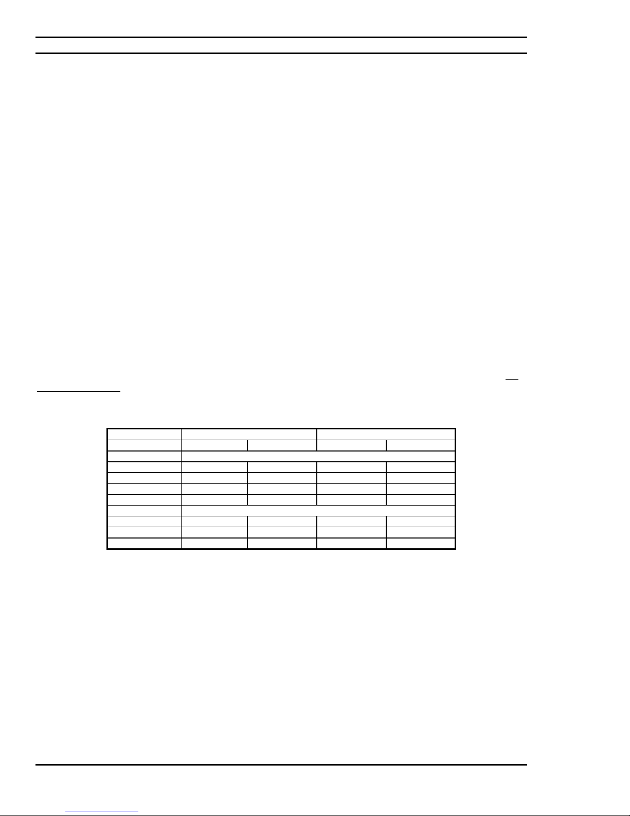
We recommend that you always install memory DIMMs in pairs, each DIMM being installed in the DIMM 0 slot of
each bank, in order to take advantage of the dual channel technology. If you ignore this recommendation, the system
will operate in single channel mode without taking advantage of the dual channel technology. The DIMM 0 slot of
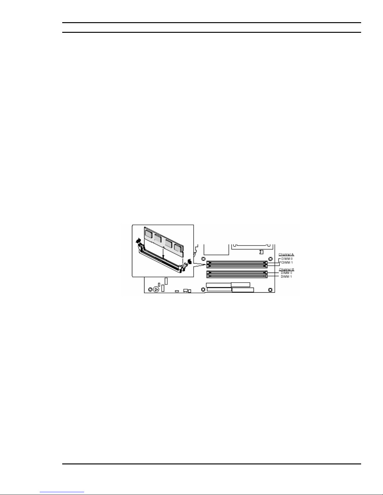
Channel A is the one closest to the processor socket and it is coloured blue. The following figure illustrates the
optimal possibilities:
Channel A Channel B
TOTAL MEMORY DIMM 0 DIMM 1 DIMM 0 DIMM 1
Dual Channel with Dynamic mode
512 MB 256 MB 256 MB
1 GB 256 MB 256 MB 256 MB 256 MB
2 GB 512 MB 512 MB 512 MB 512 MB
4 GB 1 GB 1 GB 1 GB 1 GB
Dual Channel without Dynamic mode
1.5 GB 512 MB 256 MB 512 MB 256 MB
2.5 GB 1 GB 256 MB 1 GB 256 MB
3 GB 1 GB 512 MB 1 GB 512 MB
Figure 4.5: Ciara Enterprise/Discovery 945GTP Main Memory Expansion Options
Minimum memory configuration for the system is 128 MB. The maximum memory configuration is 4 GB.
- 36 -
Page 37
Ciara Enterprise/Discovery 945GTP
Installing DIMM Modules
Install a DIMM module into a memory socket on the system main board, as follows:
1. First, make sure the power is turned Off and the power cord is unplugged. Then
remove the case cover.
2. Align the module so that the pin 1 marking on the module corresponds to the DIMM socket
pin 1 marking. The module can only fit in the socket in one way; you cannot insert the
DIMM incorrectly.
3. Slide the module into the socket at a 90-degree angle to the main board. (See figure 4.6)
4. After inserting the DIMM module completely into the socket, push up on the socket latches
securing the DIMM into place.
NOTE: To release the memory module, push both latches down and carefully rock the module away from the main
board. You should then be able to pull the module up and out of the socket.
Figure 4.6: Installing DIMM Memory Modules
- 37 -
Page 38

Ciara Enterprise/Discovery 945GTP
4.9: System Maintenance
Read and follow carefully all the instructions and warnings in this manual and on these products!
Only use a damp cloth to clean your system unit and monitor case. Do not use
detergents!
Position your system unit, monitor and cables/wires away from direct sunlight, moisture,
dust, oil, and thoroughfares.
Ensure that all ventilation outlets are always free from obstruction.
In the event of mechanical/power failure or damage, do not attempt to repair the system
unit, monitors, cables /wires. Refer all such problems to experienced service personnel.
Ensure that the back of the system unit is at least 6" away from anything that might
obstruct the ventilation outlets and cause overheating.
Ensure that the power source is grounded correctly. This product is equipped with a 3-
wire grounding-type plug. This plug will only fit into a grounded power outlet.
- 38 -
Page 39

Ciara Enterprise/Discovery 945GTP
5.0: Using the Ciara Enterprise/Discovery 945GTP
5.1: Introduction
The Ciara Enterprise/Discovery 945GTP is a powerful personal computer that has the ability to run a variety of
operating systems. Unless you have specified something different, your system comes configured with a Windows
operating system pre-loaded onto the hard drive. Each operating system comes with its own user manuals, and you
should refer to these for information specific to your system.
5.2: A Caution about Viruses
Due to the prevalence of computer viruses, we strongly recommend that you take precautions to protect your
computer from them. Purchase and use a reputable virus-checking program. Ensure that the program is kept up to
date by registering the program, and installing updates as they are provided. Please be aware, however, that even the
best virus checking programs cannot be regarded as the perfect solution. It is possible for even the best program to
fail, particularly if it is not upgraded. Please speak to your Ciara account representative for more information.
5.3: Windows
Windows is a Graphical User Interface (GUI) that provides a screen composed of icons. You select or “click” on the
icons to run programs. As noted above, Windows has been installed on your computer. For further information
about using Windows, please consult the appropriate Microsoft software manual provided with your Ciara
Enterprise/Discovery 945GTP.
5.4: Windows 2000 Server, Windows 2003 Server & Novell NetWare
Windows 2000 Server, Windows 2003 Server and Novell NetWare are operating systems that provide sophisticated
networking capabilities to Windows and OS/2 based computers. The addition of a Network Interface Card (NIC) in
the computer allows the user to connect the Ciara Enterprise/Discovery 945GTP to a network server computer
running 2000 Server, 2003 Server or NetWare.
Microsoft and Novell provide workstations on the network with access to files and applications stored on the file
server (a dedicated computer running the 2000 Server, 2003 Server or NetWare operating systems), as well as access
to shared printers on the network. Sophisticated tools are built into the 2000 Server, 2003 Server and NetWare
operating systems to manage the network, and to restrict access to resources on the file server.
For further information about Windows 2000 Server, 2003 Server or Novell NetWare, please consult the manuals
provided with the network operating system (NOS), or speak to your service representative.
- 39 -
Page 40

Ciara Enterprise/Discovery 945GTP
6.0: Documenting your computer
Ciara Technologies Inc. recommends that you record the information about your computer and keep a copy of this
in a safe but readily accessible location.
Please keep your equipment log up to date and include a copy of it whenever your equipment is returned to Ciara
Technologies Inc. for servicing.
The equipment log is also helpful if your Ciara computer is lost, stolen, or damaged. It can serve as your record of
when the equipment was placed in service, and the dates of all equipment upgrades and configuration changes.
Record the model and serial numbers of the system components, dates of component removal and/or replacement.
Be sure to include the same information for any components added to the system, such as fixed disk and floppy disk
drives, add-in boards, or printers. Record the model and serial numbers of the Ciara System. The model and serial
numbers of the System Unit are recorded on the label attached to the rear cover.
The location of serial numbers on add-in boards, fixed and floppy disk drives, and external equipment, such as video
displays or printers, varies from one manufacturer to another, but should be easily recognizable.
- 40 -
Page 41
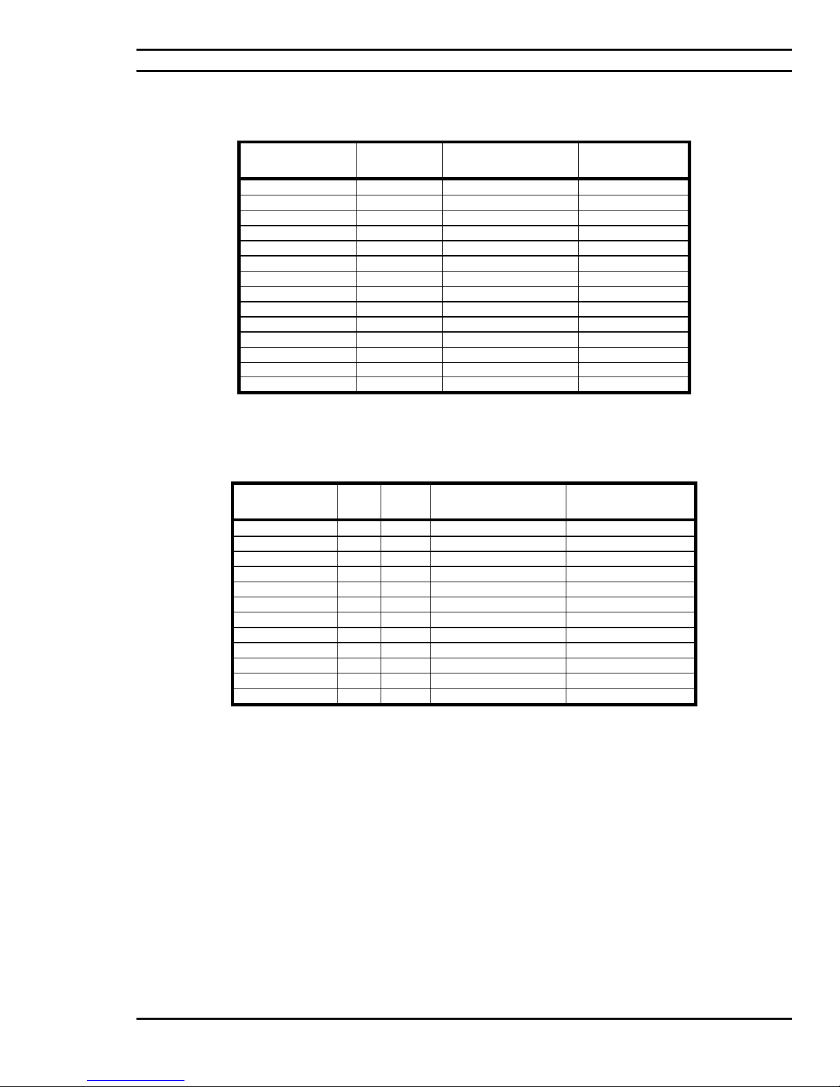
6.1: Base System Details
Component Purchase
System Unit
Mainboard
Memory
Processor
Video Card
Sound Card
LAN Card
Hard Drive
CD-ROM Drive
DVD-ROM Drive
CD/DVD-Writer
Mouse
Keyboard
Monitor
Ciara Enterprise/Discovery 945GTP
Model Serial Number
Date
6.2: Hardware Configuration
Device IRQ DMA I/O Port
COM1
COM2
Primary IDE
Secondary IDE
LPT1
Mouse
LAN Card
Sound Card
Video Card
USB
Shared Memory
Addresses
- 41 -
Page 42
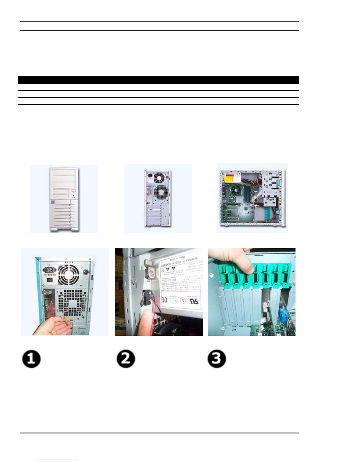
Ciara Enterprise/Discovery 945GTP
7.0: Quick installation guide
7.1: Mid-Tower Chassis Characteristics
Mid-Tower Specifications
Motherboard Type: ATX (12"x 9.6") or Micro ATX ( 9.6"x 9.6")
Drive Bay Space: Ext. 3 x 5.25", Ext. 2 x 3.5", Int. 2 x 3.5"
Power Source: 300 W
Peripheral Space: 2 PCI Express x1 slots, 4 conventional PCI slots and one
video PCI Express x16 slot
Dimensions (mm without bezel) : 425(H) x 198(W) x 465(D)
Front Fans: 1 x 80mm, 1 x 90mm, or 120mm
Rear Fans : 1 x 80mm, 1 x 90mm, or 120mm
Security: Lock and intrusion
Sheet Metal Thickness (mm): 0.8mm
Front
Rear
Side Internal
Security lock
Chassis intrusion
switch
- 42 -
Tool-less PCI slots
retention mechanism
Page 43
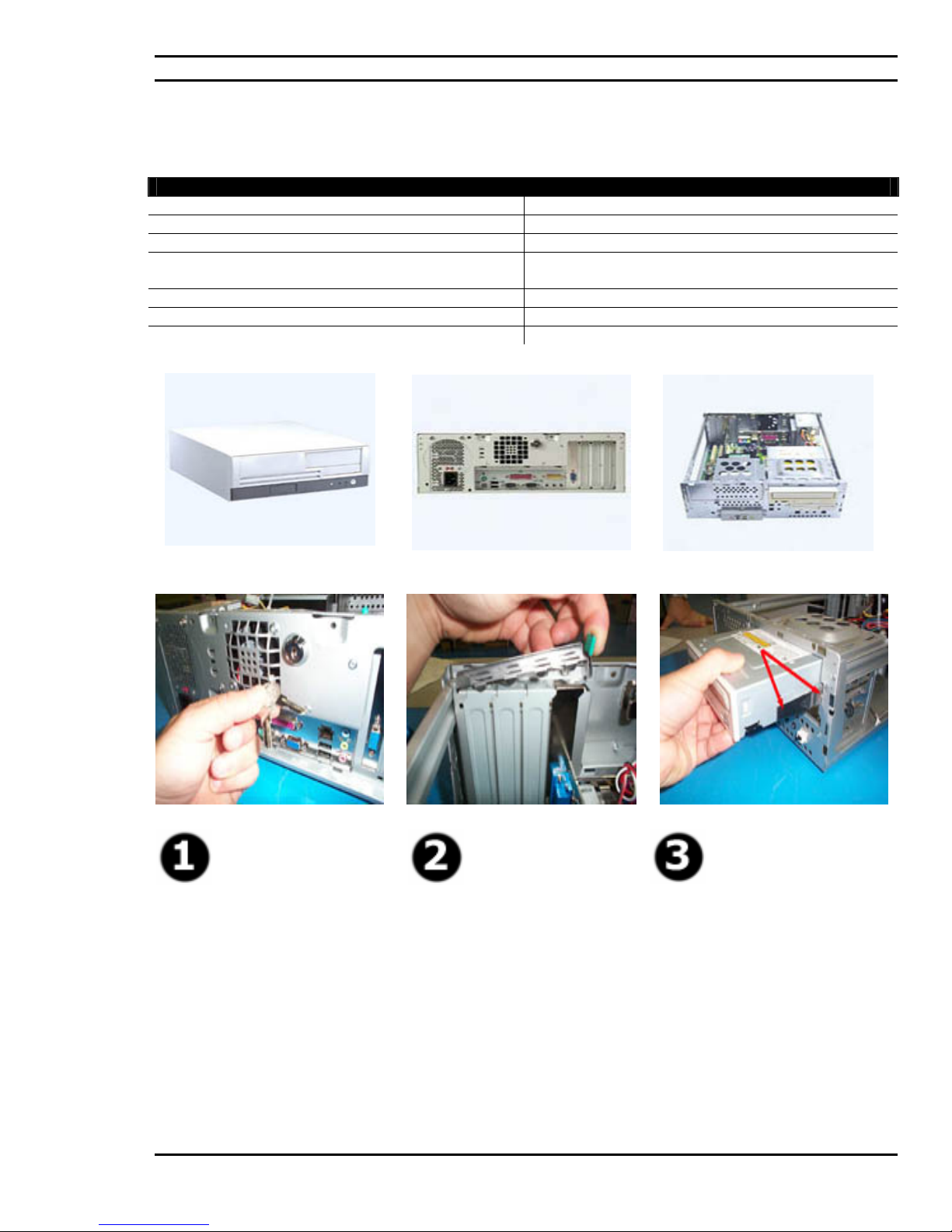
Ciara Enterprise/Discovery 945GTP
.
7.2: Small Form Factor Chassis Characteristics
Small Form Factor Specifications
Type of Motherboard Micro ATX ( 9.6"x 9.6")
Drive bay space Ext. 1 x 5.25", Ext. 1 x 3.5", Int. 1 x 3.5"
Power supply 200 W
Peripheral space 1 PCI Express x1 slots, 2 conventional PCI slots and one
video PCI Express x16 slot
Dimensions (mm, without front bezel) 133(H) x 360(W) x 390(D)
Security Chassis lock and intrusion
Metal thickness 0.8mm
Front Rear Internal
Security lock.
Tool-less PCI cards
retention mechanism.
Tool-less peripheral
slide-in rails.
- 43 -
Page 44
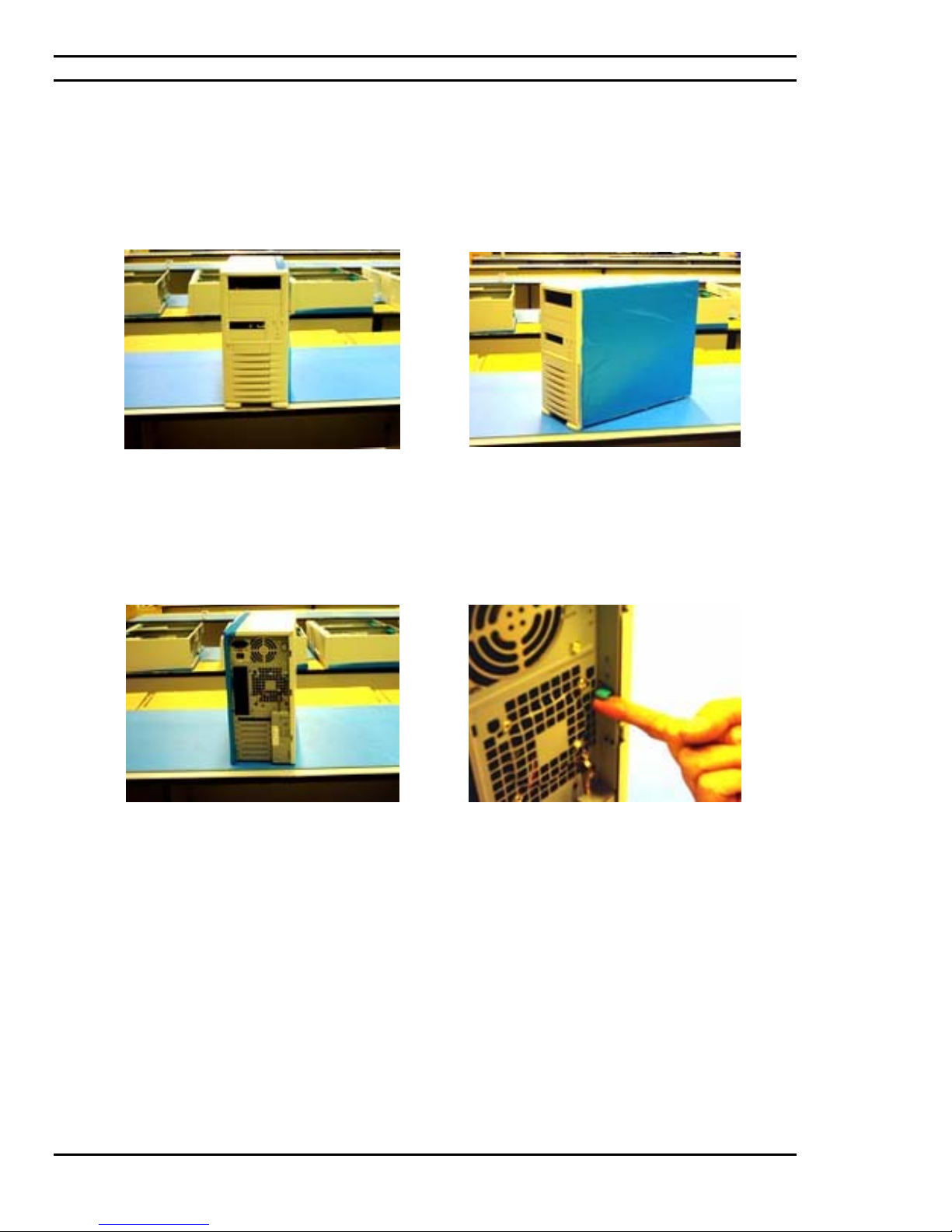
Ciara Enterprise/Discovery 945GTP
7.3 : Opening and accessing the chassis
The front of the chassis, access to the front 5.25 and
3.5 bays, front panel USB and audio connectors and
power on button.
This picture shows the back of the casing, the rear
doors for peripheral installation, the back plate area
for which connectors related to the motherboard
(once installed) will be accessed, and the power
supply area.
The side of the casing and a protective layer of blue
vellum for which protects the casings side, typically
the side where the casing lies during installation.
A vertical lever for which once activated allows for
the unlocking of one panel side cover. Once
removed this will grant access to the inside of the
casing for modular installation.
- 44 -
Page 45
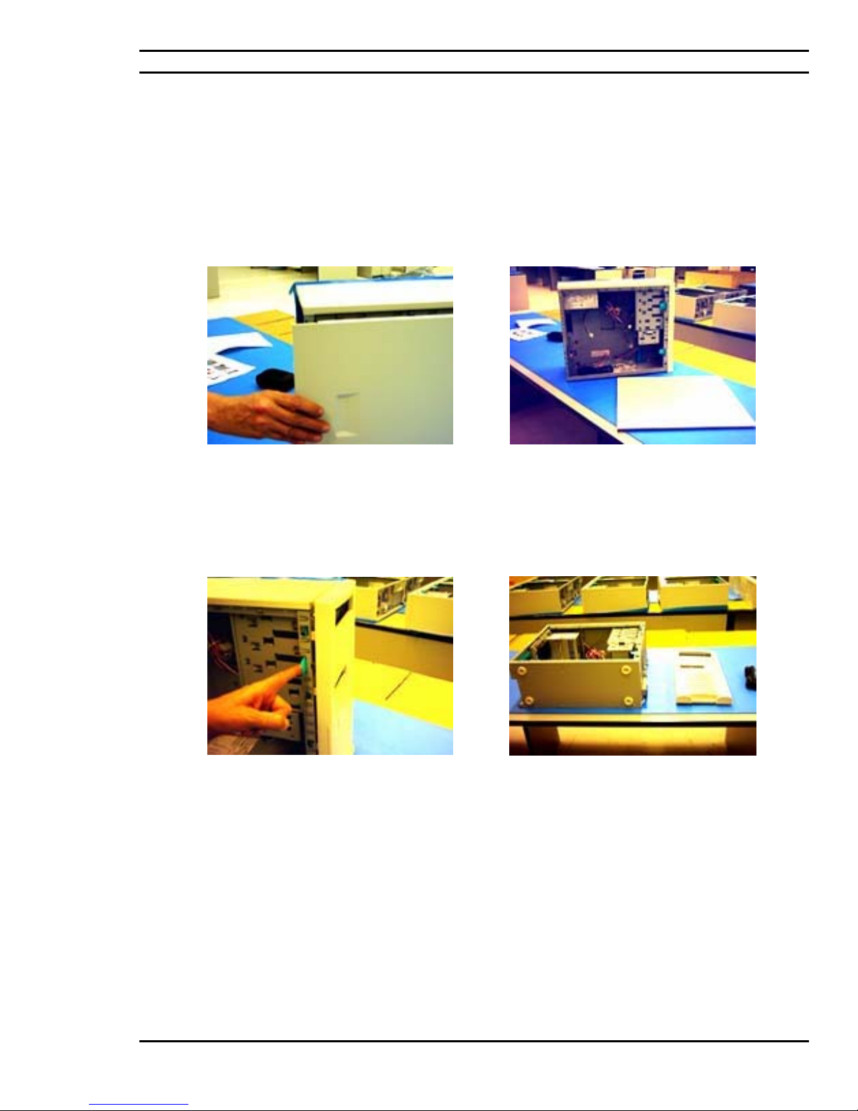
Ciara Enterprise/Discovery 945GTP
7.3 : Opening and accessing the chassis (followed)
The side panel is then removed from the chassis
allowing for modular installation and chassis
preparations.
The casing with its side exposed in addition to its
cover that was removed at its side
A tool-less lever is made available for the removal
of the facade of the chassis. This is required for the
installation of optical and/or floppy drives.
The chassis is then placed on its side, protected by
its vellum layer. The facade removed and to the
side of the chassis.
- 45 -
Page 46
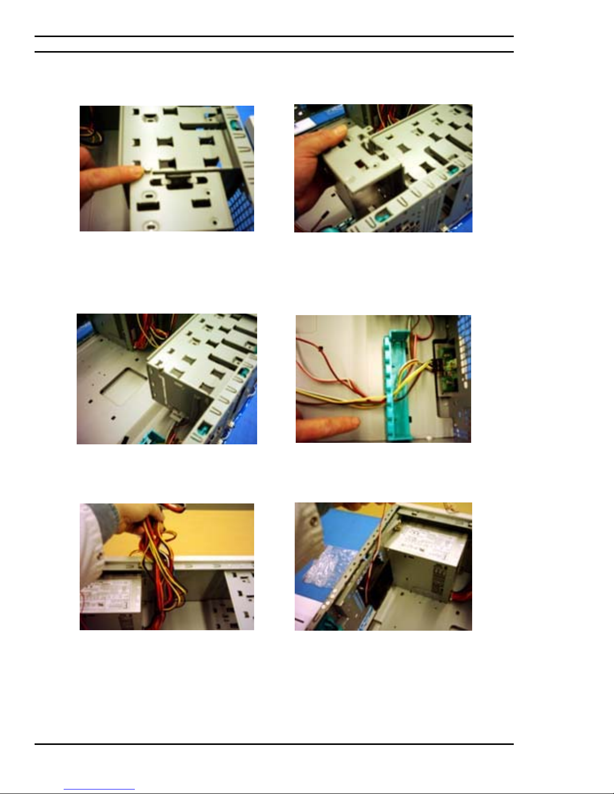
Ciara Enterprise/Discovery 945GTP
7.4: Preparing the chassis for installation
The inside of the chassis contains an area
designated for hard drive installation and more
specifically a hard drive cage. This cage is
installed onto the chassis by means of a
thumbscrew.
The thumbscrew should be replaced onto the
chassis given that the cage will eventually be
placed back in its place.
Remove the tool-less thumbscrew and proceed in
lifting the hard drive cage from the chassis. The
hard drive cage will be put aside where the hard
drive will later be installed onto it.
Front panel cables are passed through a provided
cable channel that is factory installed on the
chassis.
The chassis comes complete with a factory
installed power source or power supply. These
cables are contained and tie-rapped while taking
into consideration the modules that will be
installed and the amount of cabling needed to have
these positioned modules comfortably connected
to a power source.
The chassis fan also comes factory installed on the
chassis for which also requires the determination
of how much cabling is required and where the
power connector for the chassis fan is located on
the motherboard.
- 46 -
Page 47
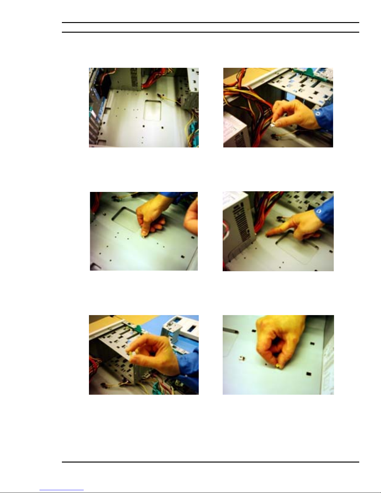
Ciara Enterprise/Discovery 945GTP
7.4: Preparing the chassis for installation (followed)
The inside of the chassis typically where the
motherboard is installed.
Two options are made available for the purpose of
elevating the motherboard once installed from the
chassis, one being chassis feet shown here, the
other being spacers.
These feet are placed into factory cut-out holes in
the chassis. Please note that each specific
motherboard will have designed areas for which
the use of these feet can be installed.
Spacers shown here are another method of
elevating the motherboard. These spacers are
provided with the chassis.
The feet are required to be installed onto the
chassis by pressing downward onto the chassis.
These spacers can be hand installed and tightened
with a spacer screwdriver.
- 47 -
Page 48
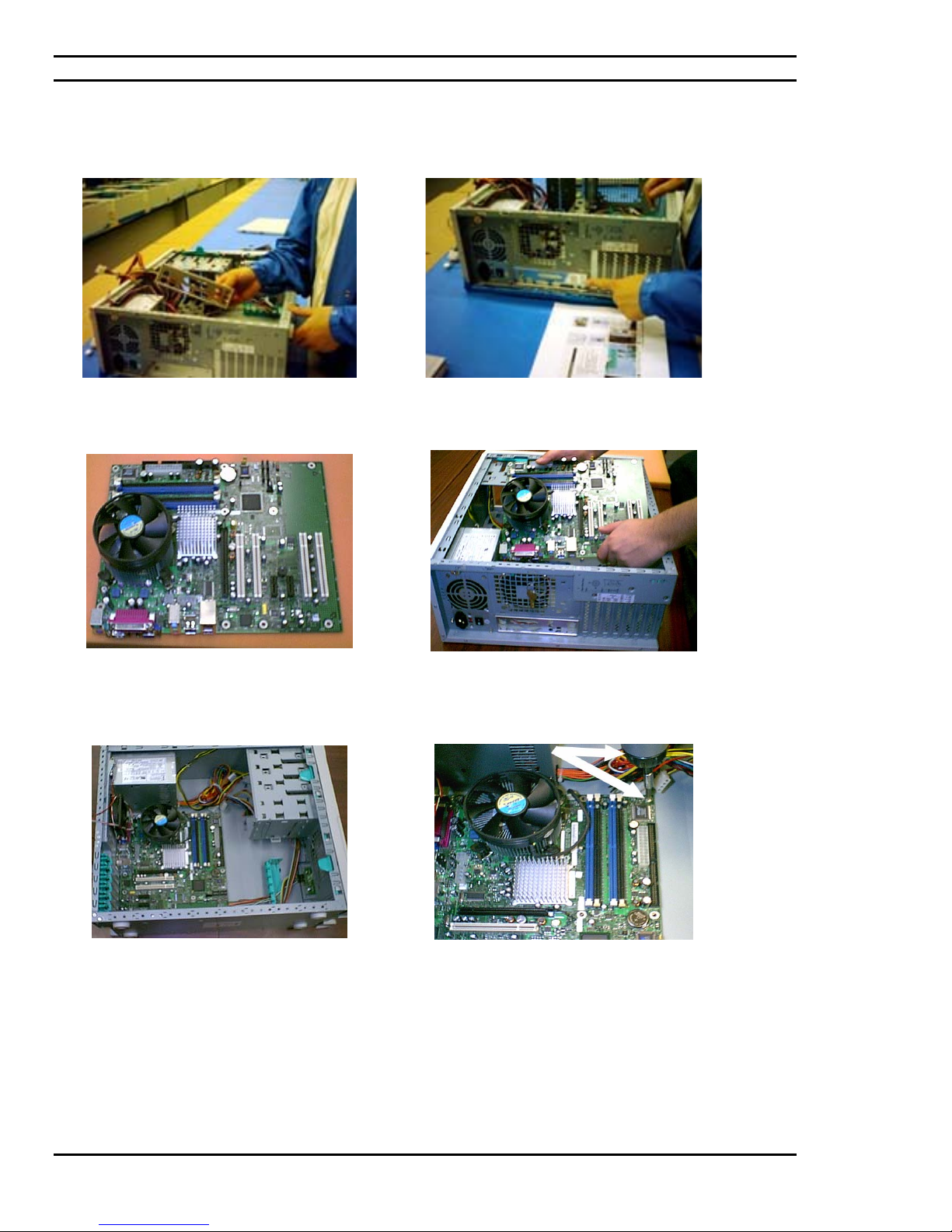
Ciara Enterprise/Discovery 945GTP
7.5: Insertion of the motherboard
A motherboard specific back plate area at the back
end of the chassis is a required installation.
The chassis’ back plate is inserted and clipped onto
its designated area.
The motherboard (pictured) can now be inserted
into the chassis given that the chassis has been
prepared for installation.
The motherboard is securely inserted into the I/O
back plate and the peripheral connectors for the
motherboard are available to have its connectors
inserted and aligned with the spacers or chassis feet
for fastening.
With the I/O connectors first the motherboard is
then inserted into the chassis in line with the spacers
and previously installed spacer feet.
The motherboard is then screwed onto the chassis.
- 48 -
Page 49
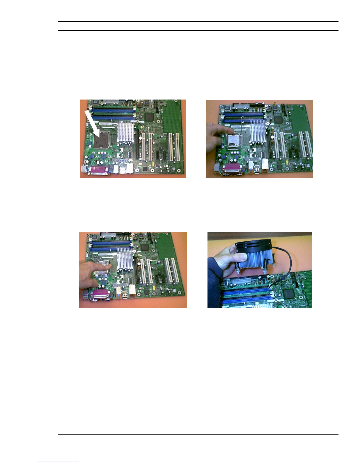
Ciara Enterprise/Discovery 945GTP
7.6: Insertion of the processor
ATTENTION: Components such as the processor may be permanently damaged by shocks arising from static
electricity. It is hence important to wear an antistatic bracelet during the installation process.
The processor can be inserted onto the
motherboard either prior or following its
installation in the chassis.
Once correctly installed, the processor socket of
the motherboard contains a fixing lever that will
lock the positioning of the processor and its pins in
place.
The processor is to be placed onto the motherboard
in its designated space while taking note of its
specific processor pin orientation.
The processor fan and heat sink module requires
installation thereafter.
- 49 -
Page 50
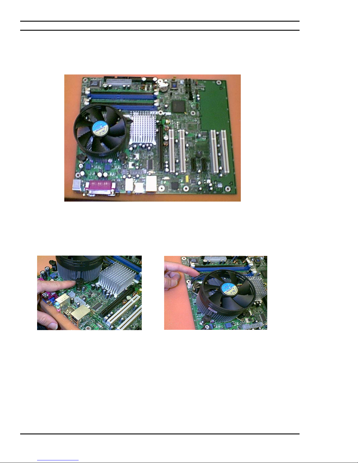
Ciara Enterprise/Discovery 945GTP
7.6: Insertion of the processor (followed)
The processor fan and heat sink module is inserted onto the housing module made available for this that
comes factory installed on several although not all motherboards.
The fastening clips allow for the fastening of the
processor fan and heat sink module to its housing
on the motherboard.
Once installed the fanned processor area will look
like this.
- 50 -
Page 51
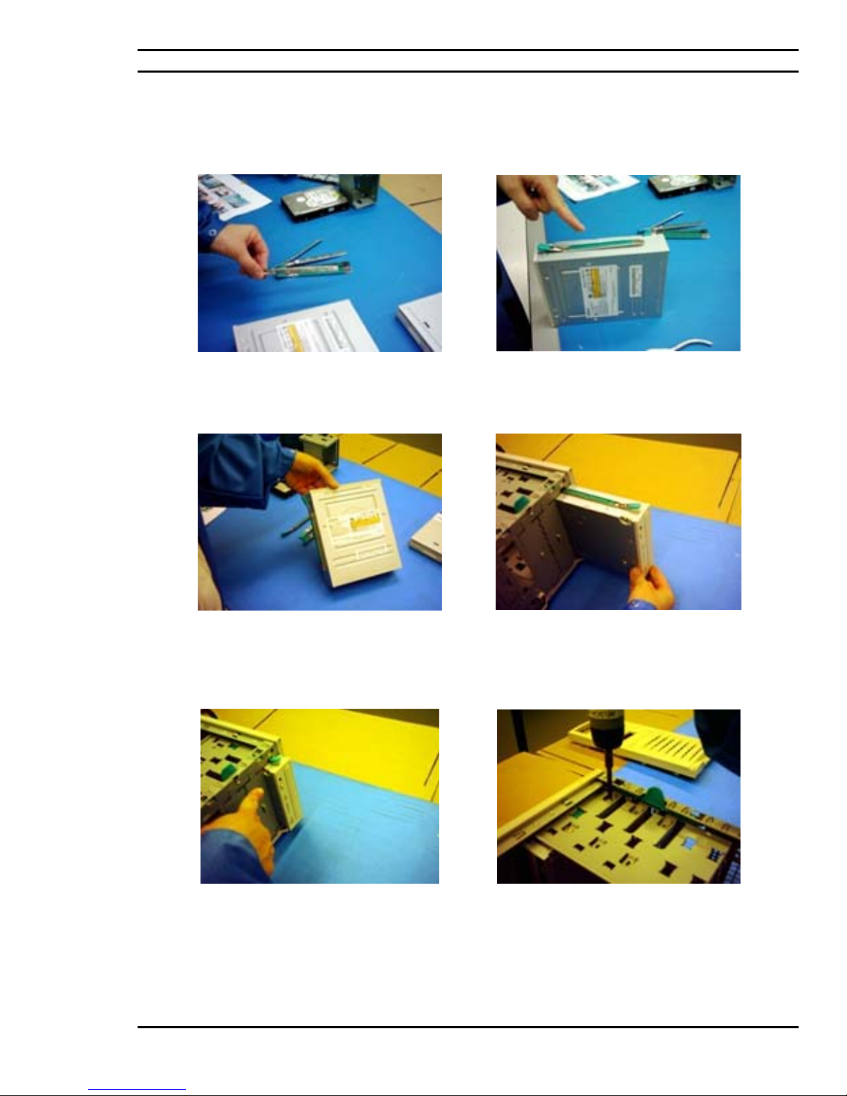
Ciara Enterprise/Discovery 945GTP
7.7: Installation of the optical drive module
Modular rails are made available with the chassis
for optical drive module installation.
The optical drive module rails once fastened
allow for one of two types of modular
installation, tool-less and permanent installation
methods.
These rails are to be fastened to the optical drive as
follows.
The optical drive then gets inserted into the chassis
from the front end of the chassis.
If a tool-less installation method is required then
the module will be snapped and inserted into the
chassis without being screwed on.
If a permanent installation is the method of choice,
the module is snapped in from the front end and
then screwed onto the chassis from the side.
- 51 -
Page 52
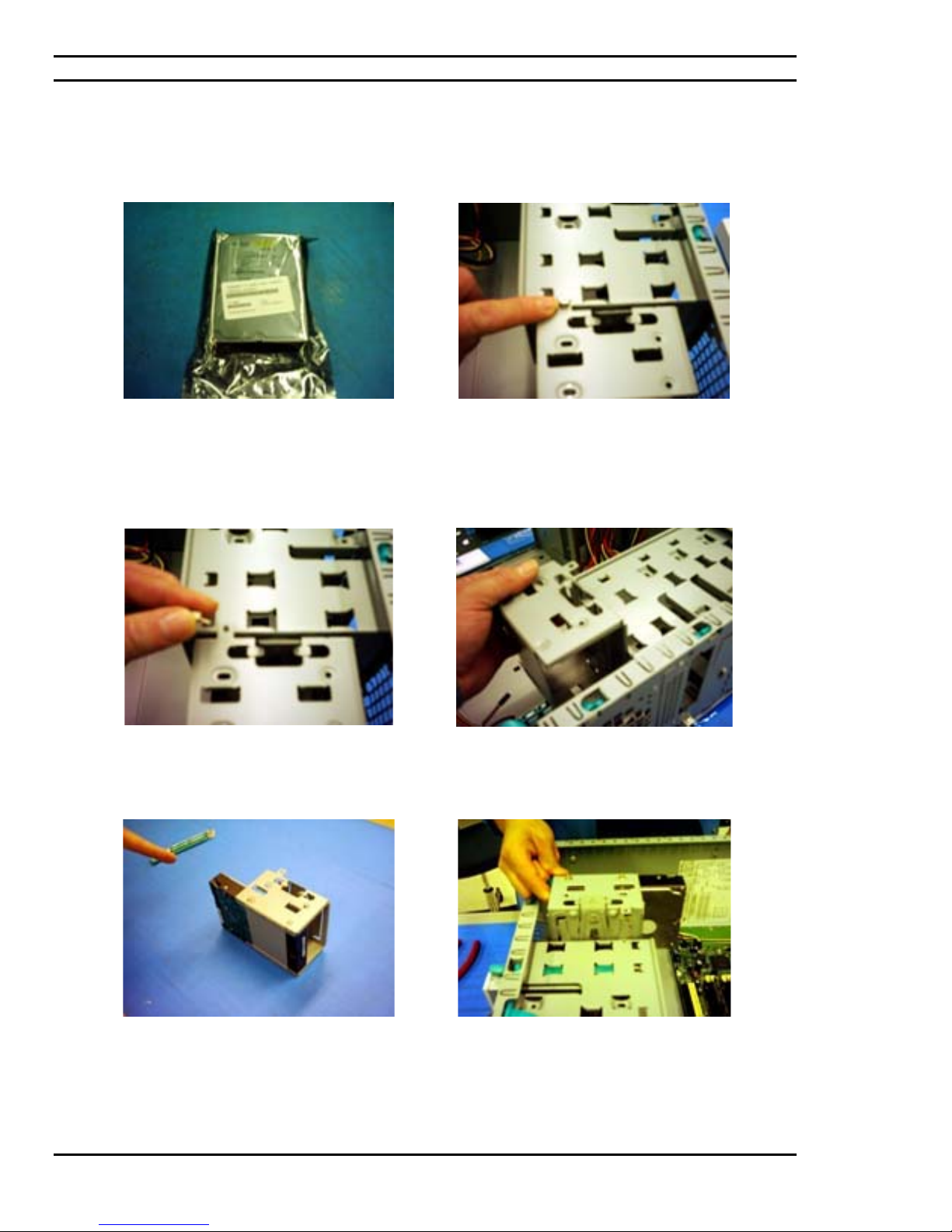
Ciara Enterprise/Discovery 945GTP
7.8: Installation of the hard drive
A typical IDE hard drive still in its packaging and
ready for installation onto its cage.
Remove the tool-less thumbscrew.
The inside of the chassis contains an area
designated for hard drive installation and more
specifically a hard drive cage. This cage is
typically installed onto the chassis by means of a
thumbscrew.
Proceed in lifting the hard drive cage from the
chassis. The hard drive cage is where the hard
drive will then be installed.
Place the hard drive into position and fasten the
hard drive by screwing it onto the hard drive
cage.
Once fastened, reinsert the hard drive cage onto
the chassis.
- 52 -
Page 53
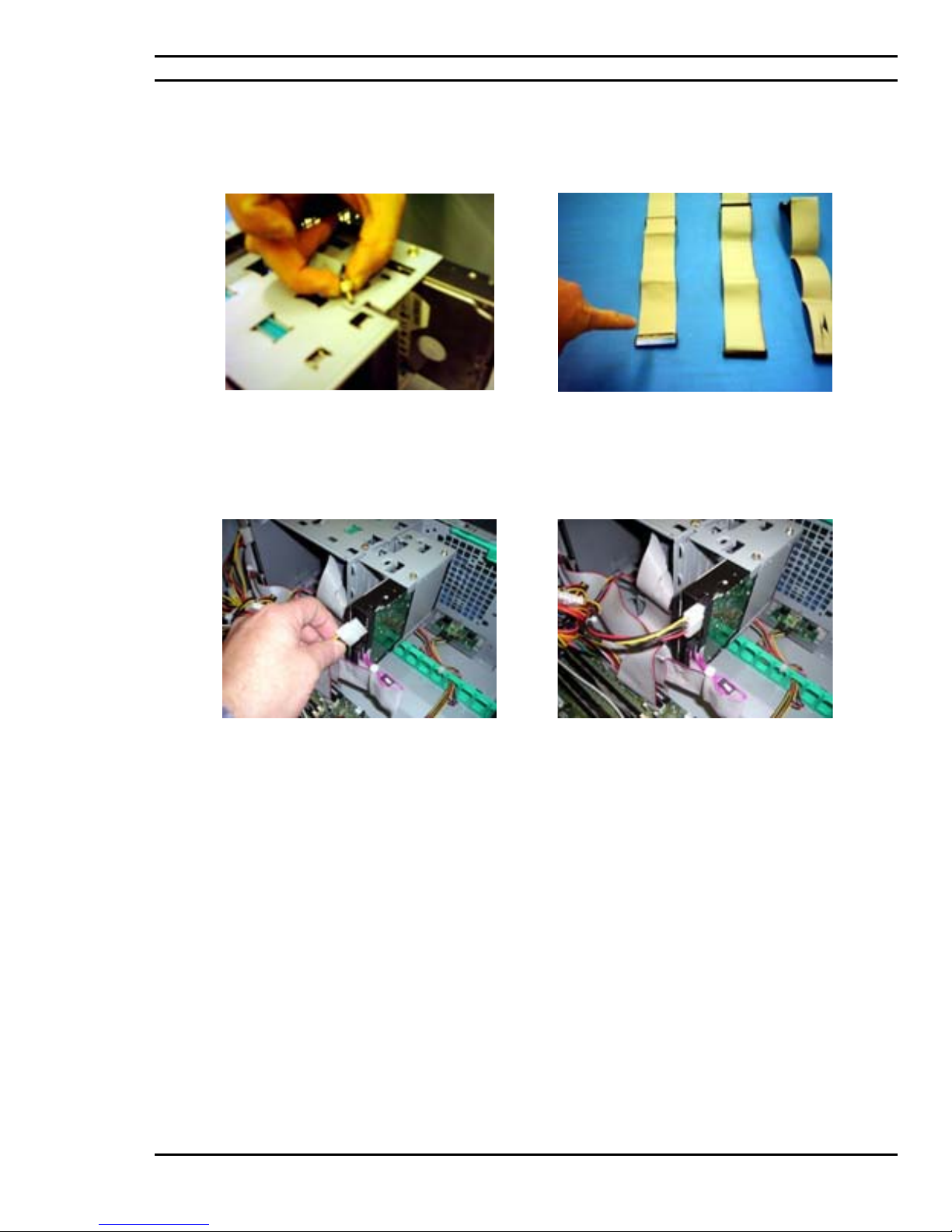
Ciara Enterprise/Discovery 945GTP
7.8:
Installation of the hard drive (followed)
Use the provided thumbscrew should there be a
requirement to have the hard drive cage remain
tool-less. Otherwise permanently fasten the hard
drive cage onto the chassis by using a regular
chassis screw.
Once done, the power source cabling for the hard
drive needs to be established and connected.
Appropriate hard drive communication cables such
as an IDE cable should be used for communication
between the motherboard controller and the hard
drive.
Hard drive installation onto its cage, in the chassis
with communication and power source
connections are complete.
- 53 -
Page 54
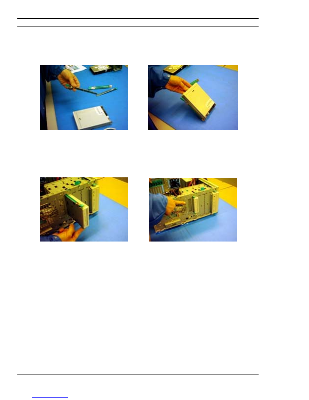
Ciara Enterprise/Discovery 945GTP
7.9: Installation of the floppy drive
Modular rails are made available with the chassis
for the floppy drive module installation.
The floppy drive then gets inserted.
These rails are to be fastened to the floppy drive as
shown.
The floppy module is snapped into place from the
front end of the chassis.
- 54 -
Page 55
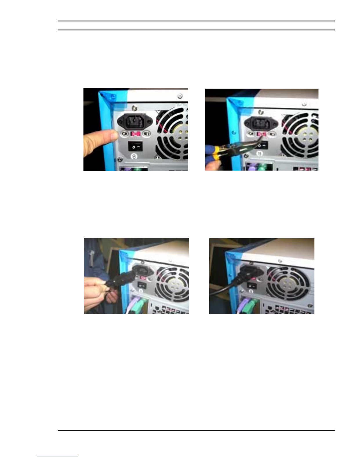
Ciara Enterprise/Discovery 945GTP
7.10: Power Considerations
Voltage selection option for the factory installed
power supply that operates at 110v or 220v. Power
supply on/off switch and connector for the
electrical power cord.
Select your voltage choice, typically 110v for use
in Canada or the United States.
The main power cable to have the chassis powered
on is a required installation. The power cable is
provided at the onset with the chassis.
The power cable for the chassis will be thereafter
connected to an electrical power outlet or power
bar.
- 55 -
Page 56
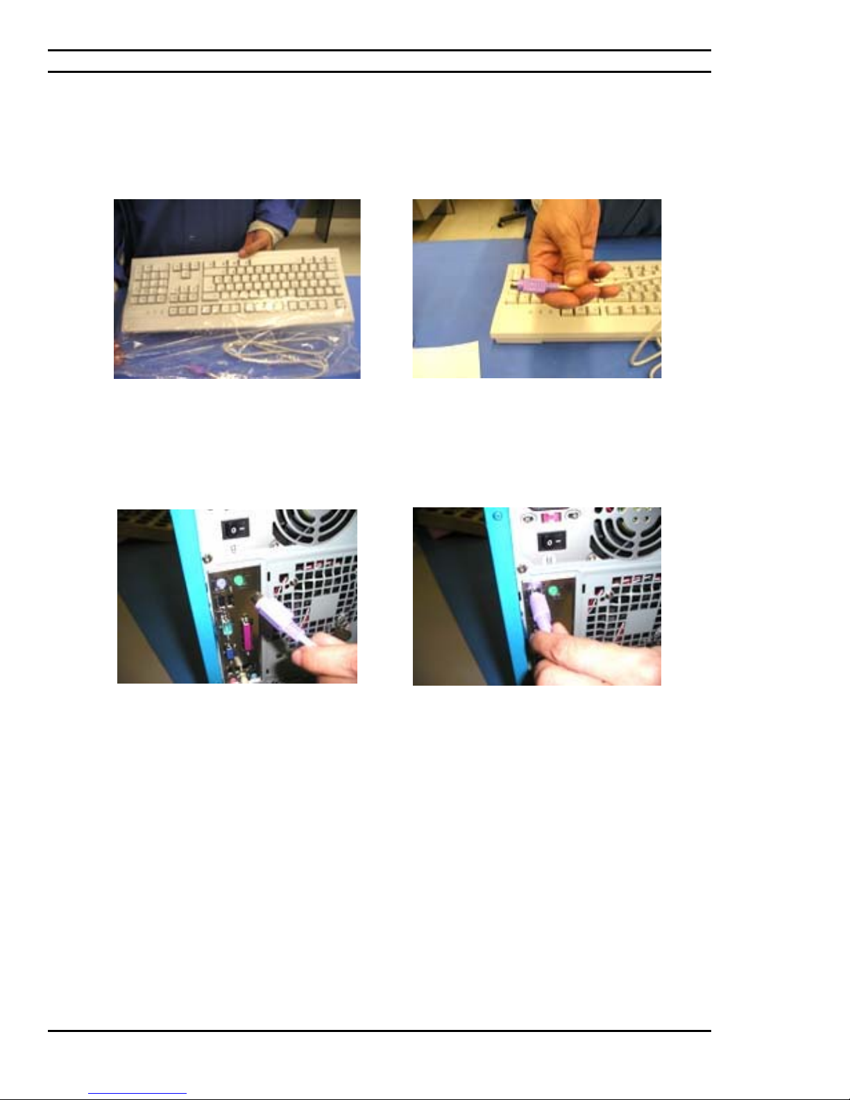
Ciara Enterprise/Discovery 945GTP
7.11: Connecting the keyboard
The depicted keyboard, a standard ACNOR
keyboard, which requires its removal from its
protective packaging.
The keyboard connector is to be placed into its
designated area on the I/O back plate of the
chassis.
The standard keyboard connector is as shown.
Connected keyboard.
- 56 -
Page 57
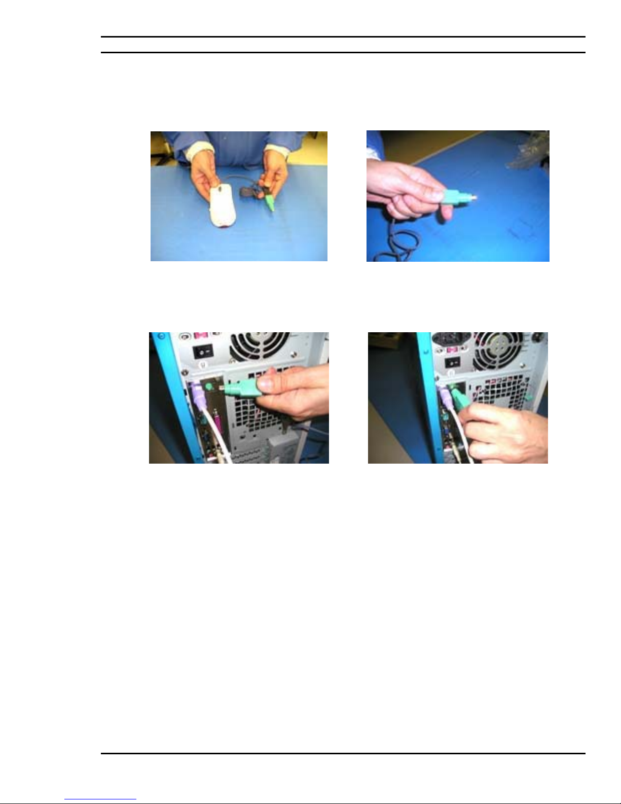
Ciara Enterprise/Discovery 945GTP
7.12: Connecting the mouse
PS/2 mouse.
The mouse connector is to be placed into its
designated area on the I/O back plate of the
chassis.
PS/2mouse connector.
PS/2 Mouse connected.
- 57 -
Page 58
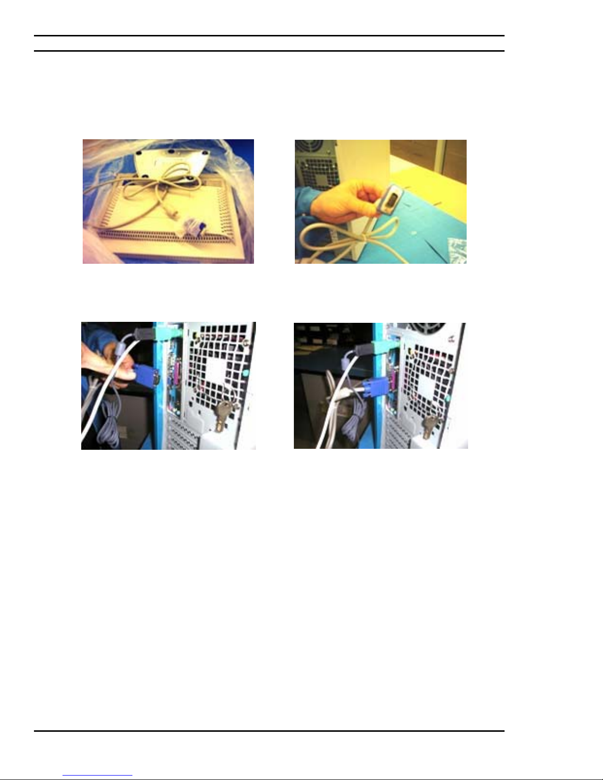
Ciara Enterprise/Discovery 945GTP
7.13: Connecting the LCD Monitor
The LCD monitor in this case, removed from its
protective packaging. The LCD comes included
with its video cable and LCD base.
The connecting of the video cable is as follows.
Screw pegs are made available on the end of the
video cable and should be fastened securely.
The LCD video cable requires insertion into its
specific video connector on the I/O back plate area
at the back of the chassis.
LCD video cable connected.
- 58 -
Page 59

Ciara Enterprise/Discovery 945GTP
7.14: Connecting the headset to the front panel of the chassis
The front of the chassis contains a push door that
can be accessed for audio, microphone and USB
connections.
This step involves the insertion of the pink
headset cable or the microphone connector for
the headset.
This particular headset has two connectors. This
step involves the insertion of the green cable or the
sound connector for the headset.
Headset connected to front panel of chassis.
- 59 -
Page 60
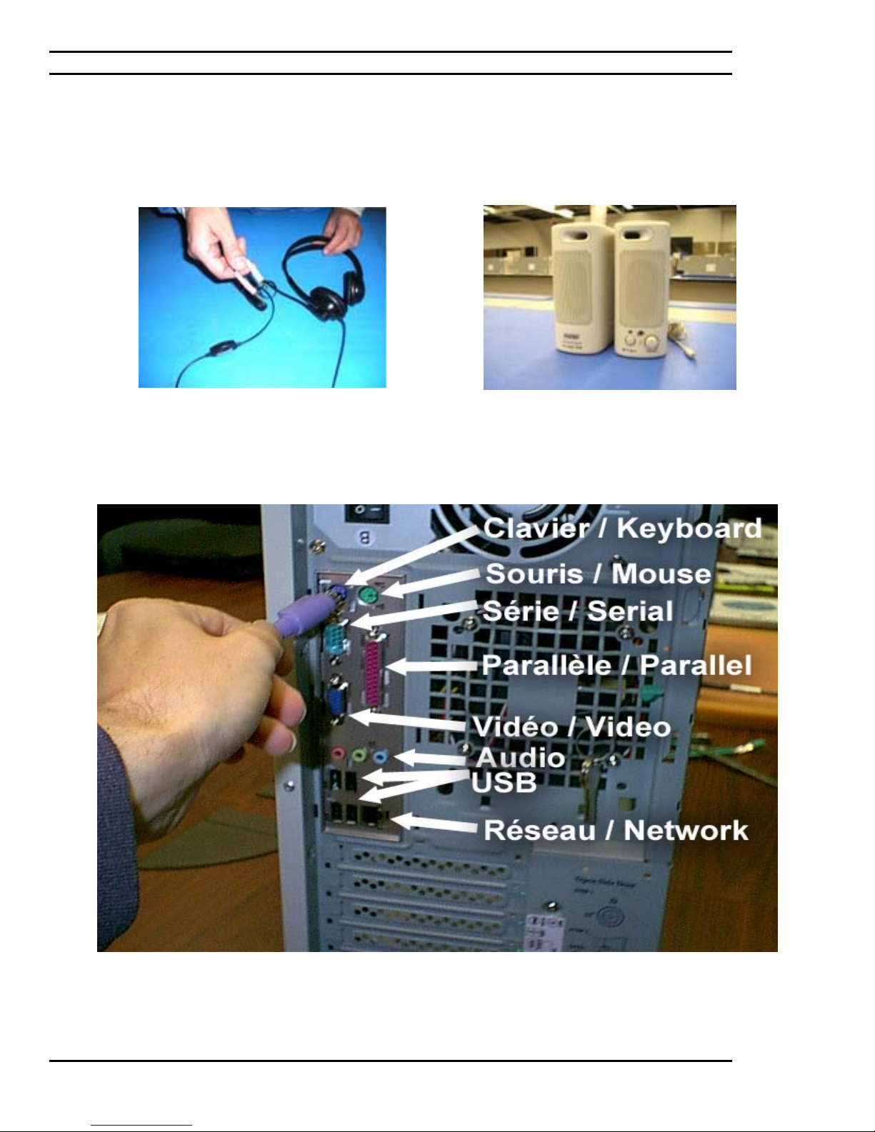
Ciara Enterprise/Discovery 945GTP
7.15: Connecting the headset and speakers to the back of the chassis
The headset in question, a combination microphone
and headphone set.
Typical audio speakers, pictured here.
Connecting cables in their designated areas (audio: green for sound and pink for microphone)
- 60 -
Page 61
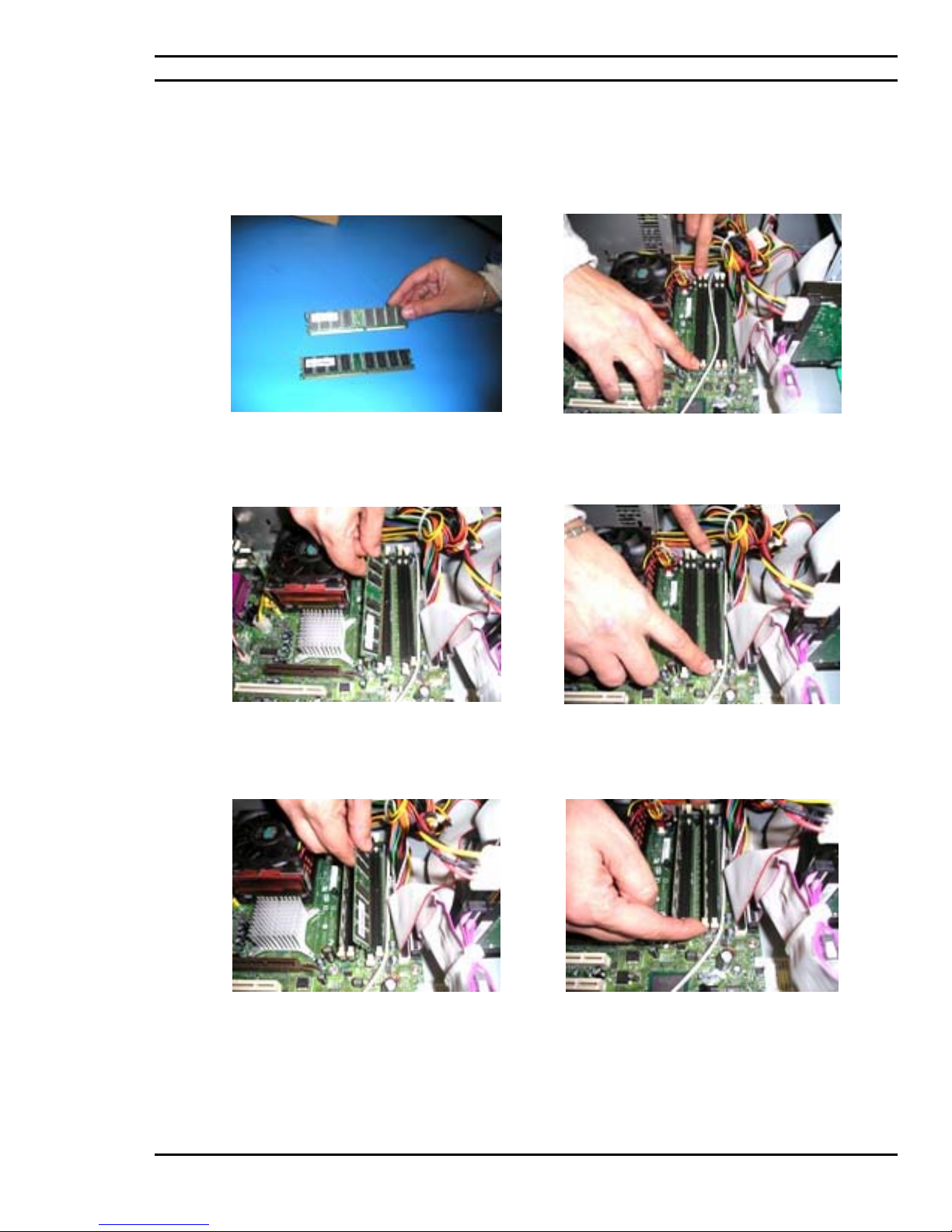
Ciara Enterprise/Discovery 945GTP
7.16: Installation of the memory modules
ATTENTION: Components such as memory may be permanently damaged by shocks arising from static
electricity. It is hence important to wear an antistatic bracelet during the installation process.
Memory modules, DDR2 256Mb PC400 Non
ECC, quantity of two in this case.
The installing of one memory module in bank
number 0 of Channel A of the motherboard in
question.
The opening of bank number 0 of Channel A
associated with the installing of the dual memory
modules in different banks.
The opening of bank number 0 of Channel B and
its memory slot.
The installing of the second memory module in
bank number 0 of Channel B of the motherboard.
Please report yourself to Section 4.5 for the various memory configurations available.
Memory module area of the motherboard with
dual memory installed in both channels of the
motherboard.
- 61 -
Page 62
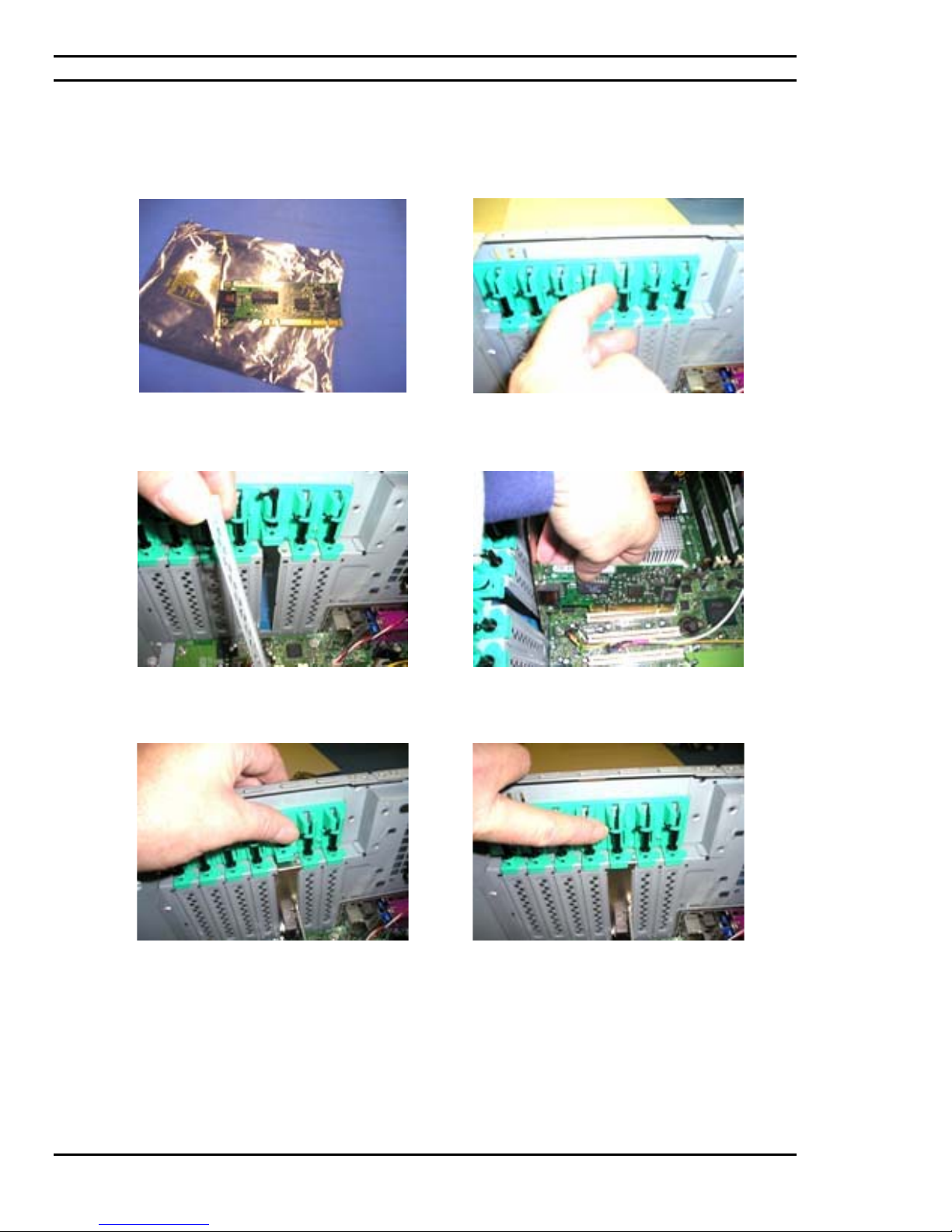
Ciara Enterprise/Discovery 945GTP
7.17: Installation of the network card
PCI Network card as shown.
Remove one chassis door in relation to the
installation of the network card in question.
Opening the tool-less latch of the chassis for the
installation of PCI peripherals onto the chassis.
Insert and secure the PCI network card into its slot
on the motherboard.
The vertical fit of the card once inserted should be
as such where the tool-less latch on the chassis is
properly secured.
Tool-less latch requires being closed after
installing the network card into the PCI slot of the
motherboard.
- 62 -
Page 63
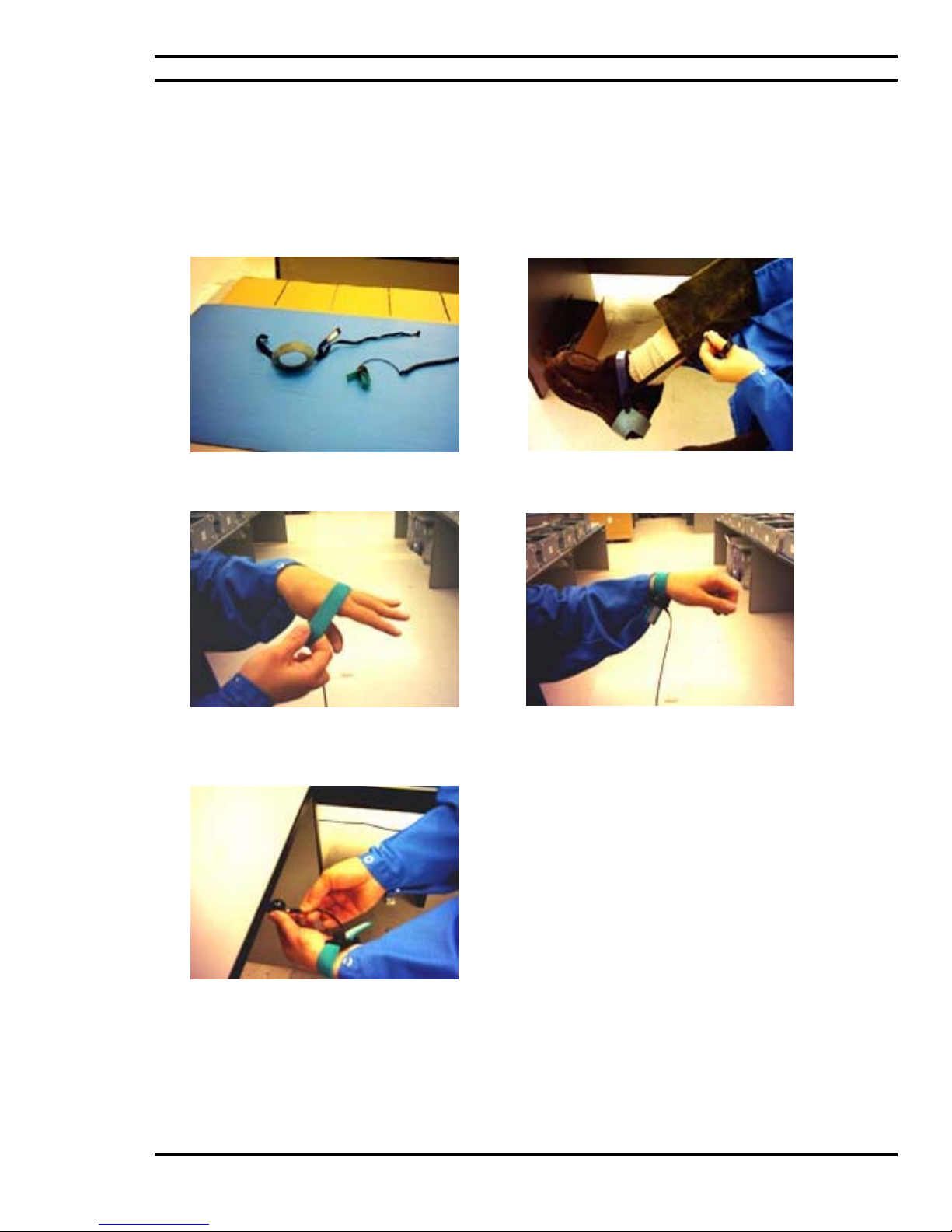
Ciara Enterprise/Discovery 945GTP
7.18: Precautions against static
ATTENTION: Components such as processors and memory may be permanently damaged by shocks
arising from static electricity. It is hence important to wear an antistatic bracelet during the installation
process. Here are a few examples of protective wear.
Typical ankle and wrist strap for anti-static use.
electricity
Putting on the anklet.
Putting on the wrist strap.
The wrist strap and its connection to a ground,
pictured here.
The wrist strap once on requires a connection to
an electrical ground.
- 63 -
Page 64

Ciara Enterprise/Discovery 945GTP
8.0: Troubleshooting your system
8.1: BIOS Errors and Messages
When the power to the Ciara Enterprise/Discovery 945GTP is first turned on, the Intel/AMI BIOS performs various
diagnostic tests. If an error occurs during these tests, then an error message will be displayed on the screen, or if the
error occurs before the display has been initialized, then the system will report the error with several beeps on the
speaker. The number of beeps and their duration characterizes the error.
Errors will either be FATAL, i.e.: the system will halt after reporting the error, or NON FATAL, i.e.: the system
may be able to boot after reporting the error, although it may not operate reliably or consistently. Please contact your
service representative if you have any questions.
8.2: Beep Codes
The following table shows the meaning of the number of beeps.
Beep Description
1 Refresh failure
2 Parity cannot be reset
3 First 64 KB memory failure
4 Timer not operational
5 Not used
6 8042 GateA20 cannot be toggled
7 Exception interrupt error
8 Display memory R/W error
9 Not used
10 CMOS Shutdown register test error
11 Invalid BIOS (e.g. POST module not found, etc.)
- 64 -
Page 65

Ciara Enterprise/Discovery 945GTP
8.3: Helpful hints
If you encounter some minor problems with the computer, monitor, or software, see the following list of general
suggestions before taking further action:
9 Check that the computer and monitor are plugged into a working electrical outlet.
9 Check if the voltage select switch is set to the appropriate voltage for your region (115V or 230V) Please
consult section 4.2 of this guide for more information.
9 Check to see that the computer is turned on and the green power light is on.
9 Check to see that the monitor is turned on and the green monitor light is on.
9 Turn up the brightness and contrast controls of the monitor if the monitor is dim.
9 Press and hold any key. If the system beeps, then the keyboard should be operating correctly.
9 Check all cable connections for loose connections or incorrect connections.
9 Wake the computer by pressing any key on the keyboard or pressing the power button. If the system
remains in suspend mode, shut down the computer by pressing and holding the power button for at least
four seconds then press the power button again to restart the computer. If the system will not shut down,
unplug the power cord, wait a few seconds, then plug it in again. The computer will restart if automatic
start on power loss is set in the BIOS. If it does not restart, press the power button to start the computer
9 Be sure that all the needed device drivers have been installed. For example, if you are using a printer, you
need a driver for that model printer.
9 Remove all diskettes from the system before turning it on.
9 If you have installed an operating system other than the factory-installed operating system, check to be sure
that it is supported on the system.
9 If the system has multiple video sources (embedded and PCI Express x16 adapters) and a single monitor,
the monitor must be plugged into the active monitor connector on the source selected as the primary VGA
adapter. Adding an PCI Express x16 adapter automatically deactivates the embedded video controller as
well as the corresponding VGA port. If this is the case of your system, connect the monitor on the VGA
port of the PCI Express x16 adapter.
CAUTION: When the computer is plugged into an AC power source, there is always voltage applied to the
system board. You must disconnect the power cord from the power source before opening the computer to
prevent system board or component damage.
- 65 -
Page 66

Ciara Enterprise/Discovery 945GTP
8.4: Solving General Problems
You should be able to easily resolve the general problems described in this section. If a problem persists and you are
unable to resolve it yourself or if you feel uncomfortable about performing the operation, contact Ciara Technologies
at 1-877-242-7272 and ask for the Customer Service department.
Problem Cause Solution
Computer appears locked up and
will not turn off when the power
button is pressed
Computer will not respond to
USB keyboard or mouse.
CAUTION: When attempting to resume from Last State mode, do not hold down the power button for more
than four seconds. Otherwise, the computer will shut down and you will lose your data.
Computer date and time display
is incorrect.
Cursor will not move using the
arrow keys on the keypad.
Poor performance is experienced Processor is hot. 1. Make sure the airflow to the computer
Hard drive is full. Transfer data from the hard drive to
Software control of the power
switch is not functional.
Computer is in Last State mode. Press the power button to resume from
RTC (real-time clock) battery
may need to be replaced.
► Connecting the computer to a
live AC outlet prolongs the life
of the RTC battery.
The Num Lock key may be on. Press the Num Lock key. The Num Lock
Solving General Problems
Press and hold the power button for at
least four seconds until the computer
turns off.
Last State mode.
. First, reset the date and time under
Control Panel (Computer Setup can also
be used to update the RTC date and time).
If the problem persists, replace the RTC
battery. See Figure 3.1 and Section 4.5 of
this guide for more information.
light should not be on if you want to use
the arrow keys.
is not blocked.
2. Make sure the fans are connected and
working properly (some fans only
operate when needed)
Make sure the processor heatsink is
installed properly.
create more space on the hard drive.
- 66 -
Page 67

Ciara Enterprise/Discovery 945GTP
8.5: Solving Power Supply Problems
Solving Power Supply Problems
Problem Cause Solution
Power supply shuts down
intermittently.
Power supply will not turn on
Computer powered off
automatically and the Power LED
flashes Red two times, once every
second, followed by a two second
pause.
Power LED flashes Red, once
every two seconds.
OR
Power LED flashes Red four
times, once every second,
followed by a two second pause
Voltage selector switch on rear
of computer chassis not
switched to correct line voltage
(115V or 230V)
because of internal power
supply fault.
Processor thermal protection
activated: A fan may be blocked
or not turning.
OR
The heatsink/fan assembly is
not properly attached to the
processor.
Power failure (power supply is
overloaded)
Select the proper AC voltage using the
selector switch. (See Figure 4.2 of the
Guide)
Contact Ciara Technology for the
replacement of the power supply.
1. Ensure that the computer air vents are
not blocked and the processor-cooling
fan is running.
2. Open hood, press the power button,
and see if the processor fan spins. If
the processor fan is not spinning,
make sure the fan's cable is plugged
onto the system board header. Ensure
the fan is fully/properly seated or
installed.
3. If fan is plugged in and seated
properly, but is not spinning, then
replace the processor fan. (See article
7.3 of this Guide)
4. Reseat processor heatsink and verify
that the fan assembly is properly
attached.
1. Check that the voltage selector, located
on the rear of the power supply, is set to
the appropriate voltage. Proper voltage
setting depends on your region. (See
Figure 4.2)
2. Open the hood (See article 7.2) and
ensure the 4-wire power supply cable is
seated into the connector on the system
board
3. Check if a device is causing the
problem by removing ALL attached
devices (such as hard, diskette, or
optical drives, and expansion cards).
Power on the system. If the system
enters the POST, then power off and
replace one device at a time and repeat
this procedure until failure occurs.
Replace the device that is causing the
failure. Continue adding devices one at
a time to ensure all devices are
functioning properly.
4. If the problem persists, contact Ciara
Technology since the problem may
necessitate the replacement of the
power supply or the motherboard.
- 67 -
Page 68

Ciara Enterprise/Discovery 945GTP
Solving Power Supply Problems (continued)
Problem Cause Solution
System does not power on and
LEDs are not flashing.
The system is unable to power
on.
Press and hold the power button for less
than 4 seconds. If the hard drive LED
turns green then check if the voltage
selector, located on the rear of the power
supply, is set to the appropriate voltage.
Proper voltage setting depends on your
region.
OR
Press and hold the power button for less
than 4 seconds. If the hard drive LED
does not turn on green then:
1.Check that the unit is plugged into a
working AC outlet.
2.Open hood and check that the power
button harness is properly connected to
the system board.
3.Check that both power supply cables
are properly connected to the system
board.
4.Ensure the 4-wire power supply cable is
seated into the connector on the system
board.
5. If the problem persists, contact Ciara
Technology since the problem may
necessitate the replacement of the power
supply or the motherboard.
- 68 -
Page 69

Ciara Enterprise/Discovery 945GTP
8.6: Solving Diskette Problems
Solving Diskette Problems
Problem Cause Solution
Diskette drive light stays on. Diskette is damaged. In Microsoft Windows 2000 and
Microsoft Windows XP, right-click
Start, click Explore, and select a drive.
Select File > Properties > Tools. Under
Error-checking, click Check Now.
Diskette is incorrectly inserted. Remove diskette and reinsert.
Drive button is not pushed in. Push in drive button.
Files on diskette are damaged. Check the program diskettes.
Drive cable is not properly
connected.
Drive not found. Cable is loose. Reseat diskette drive data and power
Removable drive is not seated
properly.
Diskette drive cannot write to a
diskette.
Diskette is write-protected. Use another diskette or remove the
Writing to the wrong drive. Check the drive letter in the path
Not enough space is left on the
Diskette is damaged. Replace the damaged disk.
Cannot format diskette. Invalid
media reported.
Diskette drive cannot read a
diskette.
You are using the wrong diskette
You are reading the wrong drive. Check the drive letter in the path
Diskette is damaged. Replace the diskette with a new one.
“Invalid system disk” message is
displayed.
Diskette error has occurred. Restart the computer by pressing the
Non-system disk message. The system is trying to start from
Cannot Boot to Diskette. Diskette is not bootable. Replace with a bootable diskette.
Diskette is not formatted. Format the diskette.
diskette.
The directory structure is bad, or
there is a problem with a file.
Diskette is not formatted. Format the diskette.
type for the drive type.
A diskette that does not contain
the system files needed to start the
computer has been inserted in the
drive.
a non-bootable diskette.
Reconnect drive cable. Ensure that all
four pins are connected.
cable.
Reseat the drive.
write protection.
statement. The default letter for the
diskette drive is “A”
Use another diskette.
In Windows 2000 and Windows XP,
right-click Start, click Explore, and
select a drive. Select File > Properties
> Tools. Under Error-checking, click
Check Now.
1.From Windows Explorer select the
disk (A) drive.
2.Right-click the drive letter and select
Format.
3.Select the desired options, and click
Start to begin formatting the diskette.
Check the type of drive that you are
using and use the correct diskette type.
statement. . The default letter for the
diskette drive is “A”
When drive activity stops, remove the
diskette and press the Spacebar. The
computer should start up.
power button.
Remove the diskette from the drive. The
computer should start up.
- 69 -
Page 70

Ciara Enterprise/Discovery 945GTP
8.7: Solving Hard Drive Problems
Solving Hard Drive Problems
Problem Cause Solution
Hard drive error occurs. Hard disk has bad sectors or has
failed.
Disk transaction problem. Either the directory structure is
bad or there is a problem with a
file.
Drive not found. Cable could be loose. Check cable connections.
Drive jumper settings may be
incorrect.
Non-system disk message. The system is trying to start from
a diskette that is not bootable.
System files missing or not
properly installed.
Second Ultra ATA hard drive
does not perform optimally.
Both slow and fast UATA devices
Computer seems to be locked up. Program in use has stopped
You are using the wrong cable for
the drive type.
are on the same data cable.
responding to commands.
Use a utility to locate and block usage
of bad sectors. If necessary, reformat
the hard disk.
In Windows 2000 and Windows XP,
right-click Start, click Explore, and
select a drive. Select File > Properties
> Tools. Under Error-checking, click
Check Now.
If the drive is a secondary drive that has
just been installed on the same cable as
the primary drive, verify that the
jumpers for both drives are set correctly.
Remove the diskette from the diskette
drive. The computer should start up.
Insert a bootable system diskette and
restart. Verify if hard drive is
partitioned and formatted. Install system
files for the appropriate operating
system if necessary.
Reinstall the second Ultra ATA hard
drive using an 80-conductor cable.
Change slow UATA devices to a
separate data cable connected to the
secondary IDE (ATA) controller on the
system board.
Attempt the normal Windows “Shut
Down” procedure. If this fails, press the
power button for four or more seconds
to turn off the power. To restart the
computer, press the power button again.
- 70 -
Page 71

Ciara Enterprise/Discovery 945GTP
8.8: Solving Display Problems
Solving Display Problems
Problem Cause Solution
Blank screen (no video). Monitor is not turned on and the
monitor light is not on.
The cable connections are not
correct.
You may have a screen blanking
utility installed or energy saver
features are enabled.
You are using a fixed-sync
monitor and it will not sync at the
resolution chosen.
Monitor cable is plugged into the
wrong connector.
Computer is in Last State mode. Press the power button to resume from
CAUTION: When attempting to resume from Last State mode, do not hold down the power button for more than
four seconds. Otherwise, the computer will shut down and you will lose your data.
Power LED flashes Red six times,
once every second, followed by a
two second pause, and the
computer beeps six times.
Monitor does not function
properly when used with energy
saver features.
Dim characters. The brightness and contrast
Cables are not properly
Pre-video graphics error. For systems with a graphics card:
Monitor without energy saver
capabilities is being used with
energy saver features enabled.
controls are not set properly.
connected.
Turn on the monitor and check that the
monitor light is on.
Check the cable connection from the
monitor to the computer and to the
electrical outlet.
Press any key or click the mouse button
and, if set, type your password.
Be sure that the monitor can accept the
same horizontal scan rate as the
resolution chosen.
If the computer system has both an
integrated graphics connector (standard
on your model) and an PCI Express x16
card connector, plug the monitor cable
into the PCI Express x16 card connector
in the expansion card area on the back
of the computer.
Last State mode.
1.Reseat the graphics card. Power on the
system.
2. If the problem persists, contact Ciara
Technology since the problem may
necessitate the replacement of the
graphics card or the motherboard.
Disable monitor energy saver feature.
Adjust the monitor brightness and
contrast controls.
Check that the graphics cable is
securely connected to the graphics card
and the monitor.
- 71 -
Page 72

Ciara Enterprise/Discovery 945GTP
Solving Display Problems (continued)
Problem Cause Solution
Blurry video or requested
resolution cannot be set.
If the graphics controller was
upgraded, the correct graphics
Install the video drivers included in the
upgrade kit.
drivers may not be loaded.
Monitor is not capable of
Change requested resolution.
displaying requested resolution.
The picture is broken up, or it
rolls, jitters, or flashes.
The monitor connections may be
incomplete or the monitor may
be incorrectly adjusted.
1.Be sure the monitor cable is securely
connected to the computer.
2.In a two-monitor system or if another
monitor is in close proximity, be sure the
monitors are not interfering with each
other’s electromagnetic field by moving
them apart.
3.Fluorescent lights or fans may be too
close to the monitor.
Monitor needs to be degaussed. Degauss the monitor. Refer to the
documentation that came with the
monitor for instructions.
Vibrating or rattling noise
coming from inside a CRT
monitor when powered on.
Clicking noise coming from
inside a CRT monitor.
Monitor degaussing coil has
been activated.
Electronic relays have been
activated inside the monitor.
None. It is normal for the degaussing coil
to be activated when the monitor is
powered on.
None. It is normal for some monitors to
make a clicking noise when turned on and
off, when going in and out of standby
mode, and when changing resolutions.
High-pitched noise coming from
inside a flat panel monitor.
Brightness and/or contrast
settings are too high.
Lower brightness and/or contrast settings.
- 72 -
Page 73

Ciara Enterprise/Discovery 945GTP
8.9: Solving Audio Problems
Solving Audio Problems
Problem Cause Solution
Sound does not come out of the
speaker or headphones.
The external speakers are not
External speakers plugged into the
Audio cable not connected. Connect audio cable between optical
Computer is in Last State mode. Press the power button to resume from
CAUTION: When attempting to resume from Last State mode, do not hold down the power button for more than
four seconds. Otherwise, the computer will shut down and you will lose your data.
Sound cuts in and out. Processor resources are being
Computer appears to be locked up
while recording audio.
Software volume control is turned
down.
turned on.
wrong audio jack.
used by other open applications.
The hard disk may be full. Before recording, make sure there is
Double-click the Speaker icon on the
taskbar, then make sure that Mute is not
selected and use the volume slider to
adjust the volume.
Turn on the external speakers.
Only one of the three audio ports is
reserved for speakers. See Figures 3.2
and 4.3 of the present guide for more
connection information.
drive and the system board.
Last State mode.
Shut down all open processor-intensive
applications.
enough free space on the hard disk. You
can also try recording the audio file in a
compressed format.
8.10: Solving Printer Problems
Solving Printer Problems
Problem Cause Solution
Printer will not print. Printer is not turned on and
online.
The correct printer drivers for the
application are not installed.
If you are on a network, you may
not have made the connection to
the printer.
Printer may have failed. Run printer self-test.
Printer will not turn on. The cables may not be connected
properly.
Printer prints garbled information. The correct printer driver for the
application is not installed.
The cables may not be connected
properly.
Printer memory may be
overloaded.
Printer is offline. The printer may be out of paper. Check the paper tray and refill it if it is
Turn the printer on and make sure it is
online.
Install the correct printer driver for the
application.
Make the proper network connections to
the printer.
Reconnect all cables and check the
power cord and electrical outlet.
Install the correct printer driver for the
application.
Reconnect all cables.
Reset the printer by turning it off for
one minute and then turn it back on.
empty. Select online.
- 73 -
Page 74

Ciara Enterprise/Discovery 945GTP
8.11: Solving Keyboard and Mouse Problems
Solving Keyboard Problems
Problem Cause Solution
The computer does not recognize
keyboard commands and typing.
Program in use has stopped
Keyboard needs repairs. Contact Ciara Technology so that we
Computer is in Last State mode. Press the power button to resume from
CAUTION: When attempting to resume from Last State mode, do not hold down the power button for more than
four seconds. Otherwise, the computer will shut down and you will lose your data.
Cursor will not move using the
arrow keys on the keypad.
Problem Cause Solution
Mouse does not respond to
movement or is too slow.
Program in use has stopped
Mouse needs repairs. Contact Ciara Technology so that we
Computer is in Last State mode. Press the power button to resume from
CAUTION: When attempting to resume from Last State mode, do not hold down the power button for more than
four seconds. Otherwise, the computer will shut down and you will lose your data.
Mouse will only move vertically,
horizontally, or movement is
jerky.
Keyboard connector is not
properly connected.
responding to commands.
The Num Lock key may be on. Press the Num Lock key. The Num
Solving Mouse Problems
Mouse connector is not properly
plugged into the back of the
computer.
responding to commands.
Mouse roller ball is dirty. Remove roller ball cover from the
1.On the Windows Desktop, click Start.
2.Click Shut Down. The Shut Down
Windows dialog box is displayed.
3.Select Shut down.
4.After the shutdown is complete,
reconnect the keyboard to the back of
the computer and restart the computer.
Shut down your computer using the
mouse and then restart the computer.
may proceed to repairs.
Last State mode.
Lock light should not be on if you want
to use the arrow keys.
Shut down the computer. After the
shutdown is complete, plug the mouse
connector into the back of the computer
and restart the computer.
Shut down the computer using the
keyboard and then restart the computer
may proceed to repairs.
Last State mode.
bottom of the mouse and clean it with a
mouse cleaning kit available from most
computer stores.
- 74 -
Page 75

Ciara Enterprise/Discovery 945GTP
8.12: Solving Hardware Installation Problems
Solving Hardware Installation Problems
Problem Cause Solution
A new device is not recognized as
part of the system.
Cable(s) of new external device
Power switch of new external
When the system advised you of
Computer will not start. Wrong memory modules were
Power LED flashes Red five
times, once every second,
followed by a two second pause,
and the computer beeps five
times.
Power LED flashes Red six times,
once every second, followed by a
two second pause, and the
computer beeps six times.
Device is not seated or connected
properly.
are loose or power cables are
unplugged.
device is not turned on.
changes to the configuration, you
did not accept them.
used in the upgrade or memory
modules were installed in the
wrong location.
Memory is installed incorrectly or
is bad.
Video card is not seated properly
or is bad, or system board is bad.
Ensure that the device is properly and
securely connected and that pins in the
connector are not bent down.
Ensure that all cables are properly and
securely connected and that pins in the
cable or connector are not bent down.
Turn off the computer, turn on the
external device and then turn on the
computer to integrate the device with
the computer system.
Reboot the computer and follow the
instructions for accepting the changes.
1. See Sections 4.8 and 7.3 of the
present Guide to verify if you have
installed memory modules
compatible to your system and if
they were installed correctly.
2. If the problem persists, Contact Ciara
Technology.
1.Reseat DIMMs. Power on the system.
2.Replace DIMMs one at a time to
isolate the faulty module.
3. If a faulty module is found, Contact
Ciara Technology for the replacement
of the module.
4. If the problem persists, Contact Ciara
Technology for this may necessitate the
replacement of the motherboard.
For systems with a graphics card:
1.Reseat the graphics card. Power on
the system.
2. If the problem persists, Contact Ciara
Technology for this may necessitate the
replacement of the video card or the
motherboard.
- 75 -
Page 76

Ciara Enterprise/Discovery 945GTP
8.13: Solving Memory Problems
Solving Memory Problems
Problem Cause Solution
System will not boot or does not
function properly after installing
additional memory modules.
Out of memory error. You have run out of memory to
Memory count during POST is
wrong.
Insufficient memory error during
operation.
You have run out of memory for
Power LED flashes Red five
times, once every second,
followed by a two second pause,
and the computer beeps five
times.
Memory module is not the correct
type or speed grade for the system
or the new memory module is not
seated properly.
run the application.
The memory modules may not be
installed correctly.
Too many programs are being
used.
the application.
Memory is installed incorrectly or
is bad.
Replace memory module with a module
approved for your system. See Sections
4.8 and 7.3 of the present Guide to
verify if you have installed memory
modules compatible to your system and
if they were installed correctly.
Check the application documentation to
determine the memory requirements.
Check that the memory modules have
been installed correctly and that proper
modules are used.
Close any programs that you do not
need.
Check the memory requirements for the
application or add more memory to the
computer.
1.Reseat DIMMs. Power on the system.
2.Replace DIMMs one at a time to
isolate the faulty module.
3. If a faulty module is found, Contact
Ciara Technology for the replacement
of the module.
4. If the problem persists, Contact Ciara
Technology for this may necessitate the
replacement of the motherboard.
8.14: Solving Processor
Problem Cause Solution
Poor performance is experienced. Processor is hot. 1.Make sure the airflow to the computer
Power LED is Red and stays on
OR
Power LED flashes Red three
times, once every second,
followed by a two second pause.
Problems
Solving Processor Problems
Processor is not seated properly or
not installed.
is not blocked.
2.Make sure the fans are connected and
working properly (some fans only
operate when needed)
3.Make sure the processor heatsink is
installed properly.
1.Check to see that the processor is
present.
2.Reseat the processor. See section 7.3
of the present Guide for more
information.
- 76 -
Page 77

Ciara Enterprise/Discovery 945GTP
8.15: Solving Optical Drive
In this User Guide, an optical drive is defined as a CD-ROM or a DVD-ROM or a CDRW or a DVD-R/RW.
Problem Cause Solution
System will not boot from an
optical drive.
Optical drive is not detected by
the system.
Movie will not play in the DVD
drive.
Cannot eject compact disc from
tray.
The optical drive cannot read a
disc or takes too long to start.
The DVD-ROM drive takes
CD or DVD disc is dirty. Clean CD or DVD with a CD cleaning
Recording audio CDs is difficult
or impossible.
Problems
Solving Processor Problems
Non-bootable CD in drive. Try a bootable CD in the drive.
Drive is not connected properly or
not properly configured.
Decoder software is not installed. Install decoder software.
Disc not properly seated in the
drive.
CD has been inserted upside
down.
longer to start because it has to
determine the type of media
played, such as audio or video.
Wrong or poor quality media
type.
Verify if the drive is correctly seated in
the chassis. Verify if all cables have
been correctly connected.
Note: All Ciara systems equipped with a
DVD drive at plant assembly include the
necessary Decoder software.
Turn off the computer and insert a thin
metal rod into the emergency eject hole
and push firmly. Slowly pull the tray out
from the drive until the tray is fully
extended, then remove the disc.
Re-insert the CD with the label facing
up.
Wait at least 30 seconds to let the DVDROM drive determine the type of media
being played such as audio or video.
kit, available from most computer
stores.
1.Try using a slower speed when
recording.
2.Verify that you are using the correct
media for the drive.
3.Try a different brand of media.
Quality varies widely between
manufacturers.
- 77 -
Page 78

Ciara Enterprise/Discovery 945GTP
GLOSSARY
Adapter card -- A printed circuit board that gives your computer some added capability, such as more memory, or
control of a new device. A card plugs into an expansion slot on the system board.
Analog monitor -- A type of video display that uses a continuously variable analog voltage to display a large number
of colours at resolutions up to 1024 x 768 and beyond. The voltage levels on the red, green and blue lines on the VGA
connector determine colours.
Auto switching -- The ability of a video display to detect the video display mode for a given application program and
automatically switch to that mode.
BIOS -- Basic Input Output System. Programs permanently stored in the system board's ROM chips that provide the
fundamental processes or functions of the system, such as the Power On Self Test (POST). The VGA circuitry has its
own video BIOS. See also ROM.
Bus -- A set of address or data lines used to transfer information between different components within a computer
(such as memory, the microprocessor, and slots).
Cache -- A device that contains high-speed memory and permits higher speed accesses than general-purpose memory.
Cache hit rate -- The percentage of time data is delivered from the cache rather than from main memory.
Central processing unit (CPU) -- An integrated circuit chip that performs the actual computing functions of the
computer. Other chips perform support functions like storing data and controlling peripherals. See also
microprocessor.
Chip -- An electronic device that combines thousands of transistors on a small sliver of silicon. See also integrated
circuit.
Chip set -- The logic devices on the motherboard that connects the microprocessor and other board functions.
Clock -- A circuit that sends a consistent, periodic signal that is used to step logic information through a computer
circuit.
CMOS RAM -- Complementary Metal Oxide Semiconductor. CMOS RAM stores basic configuration information
about your computer.
Colour display -- A video display capable of displaying colours based on the RGB (Red, Green, and Blue) colour-
mixing scheme.
Configuration -- The way in which a computer and peripheral equipment (such as printers and display monitors) are
interconnected and programmed to operate as a system.
Default -- The initial setting when the board left the factory.
Digital monitor -- A type of monitor in which display colour is controlled by digital colour control lines that switch
on and off; the number of colours that can be displayed depends on the selected display mode.
DIMM -- Dual In-Line Memory Module. RAM chips installed on a small circuit board module, having a single row
of connectors (184 pins) on the bottom of the module where it is plugged into the main system board.
- 78 -
Page 79

Ciara Enterprise/Discovery 945GTP
DMA (Direct Memory Address) -- A method for transferring data directly to and from system memory, bypassing
the microprocessor.
Driver -- A utility program accompanying the motherboard that permits application programs to use the extended
resolutions of the VGA circuitry.
Expansion slot -- A connector on the motherboard for holding an adapter card.
Gigahertz (GHz) -- A frequency of 1 billion cycles per second.
Hertz (Hz) -- A unit of frequency equal to one cycle per second.
Horizontal frequency -- The rate, at which monitor displays each scan line, usually measured in kilohertz (kHz).
I/O -- An abbreviation for "input/output", a generic term that refers to the devices and processes involved in the
computer's reading and writing data.
IDE -- Integrated Drive Electronics. A hard disk drive interface for use with drives that contain their own controller
electronics. With the IDE interface, a hard disk drive controller card is not necessary.
Integrated circuit -- An electronic device that combines thousands of transistors on a small chip of silicon. Such
devices are the building blocks of computers.
Interleaving -- A technique for improving the performance of system memory by splitting the memory into two or
four sections that alternately process information. While one memory section goes through a refresh cycle, the
microprocessor sends information to another section for processing.
Jumper -- On a printed circuit board, a patch connector, wire, or cable used to establish a circuit.
Megahertz (MHz) -- A frequency of 1 million cycles per second.
Memory -- Semiconductor chips used to hold information and programs while they are being accessed by the
microprocessor. See also RAM and ROM.
Microprocessor -- An integrated circuit that contains the circuits the computer needs to calculate and to
communicate with the other parts of the system. See also cent r al pr ocessing unit.
Multi-frequency monitor -- A monitor (also known by the trade names MultiSync or MultiScan) that, due to its
ability to scan at various horizontal and vertical frequencies, is capable of displaying a wide variety of resolution
modes.
Page-mode memory -- A memory arrangement that avoids wait states by allowing back-to-back memory accesses
within blocks of memory called pages. See also wait states.
Parallel interface -- A standard interface that transmits and receives data in a parallel manner, using a separate data
line for each bit.
Parity bit -- An additional non-informational bit appended to a group of bits to make the number of ones in the group
of bits either an odd or even number; an elementary mechanism for error checking.
Peripheral -- A hardware device (such as a keyboard, monitor, or printer) that connects to a computer.
Pin -- Any of the leads on a device, such as a chip, that plug into a socket and connect it to a system.
- 79 -
Page 80

Ciara Enterprise/Discovery 945GTP
Pixel -- Short for "picture element", the smallest single dot displayable on the display.
Power-On Self Test (POST) -- Internal test procedures that the BIOS runs automatically when the system is turned
on. These procedures verify that all the computer's hardware is functioning properly. If the test detects problems, the
computer displays error codes before (or instead of) starting the operating system. The error codes can help a service
person determine what is wrong with your computer.
RAM -- An acronym for "random-access memory." The type of computer memory used to store information while a
program is running. All data stored in RAM is lost when the computer is turned off or power is lost.
Refresh -- Periodic rewrite of system memory contents to the same memory locations by the microprocessor so that
the contents do not decay beyond redemption.
Resolution -- A measure of the quality of the image that can be shown on a particular display; usually expressed as
the number of pixels that can be displayed horizontally across the display screen by the number of pixels that can be
displayed vertically on the display screen.
ROM -- An acronym for "read-only memory." The type of computer memory that is used to permanently store the
information vital to computer operation, including some parts of the operating system. ROM is permanent and the
contents will not be lost when the computer is turned off.
SCSI -- An acronym for Small Computer Systems Interface. An interface that allows you to connect several
peripherals (hard drives, CD-ROM drives and tape backup units) to your computer system using a daisy-chained
controller cable.
Serial interface -- An interface that transmits and receives data in a serial manner, transmitting or receiving data one
bit at a time.
Set-up -- The arrangement of connections between an assembly of individual computing units, and the adjustments
needed for the computer to operate.
SRAM -- Static Random Access Memory. A type of memory that does not need to be refreshed. Data stored in the
SRAM remains until changed or until the computer is turned off.
System -- An assembly of components united by some form of regulated interaction to form an organized whole.
System board -- The large printed-circuit board in a computer on which most electronic devices are mounted; the
primary board in a computer. All other interfaces receive control signals or information from the system board. Also
commonly referred to as a "motherboard" or "main board".
USB -- Universal Serial Bus. USB 1.1 is a hot pluggable daisy chained 12 MB/Sec serial bus. USB 2.0 is a hot
pluggable daisy chained 480 MB/Sec serial bus. Devices may be plugged in or out without turning off the system.
USB devices include mice, scanners, keyboards, and digital cameras.
Wait states -- A delay in the computer's information processing cycle caused by a difference in speed between a
faster processor and slower memory, which holds data. Zero wait states means the processor does not have to "wait"
for memory, and can access data as fast as it is needed.
Word -- The set of bits comprising the largest unit that the computer can handle in a single operation.
- 80 -
Page 81
NOTES:
Ciara Enterprise/Discovery 945GTP
- 81 -
 Loading...