

Page 1
OPERATING INSTRUCTIONS
DUAL INPUT K/J THERMOMETER
802
802U
USB & DC Power
802W Wireless
802UW
USB & DC Power & Wireless
(802W/802UW)
INTRODUCTION
This instrument is a 5 digit, compact-sized portable
digital thermometer designed to use external K-type and J
type thermocouples as temperature sensor. Temperature
indication follows Reference Temperature/Voltage Tables
(N.I.S.T. Monograph 175 Revised to ITS-90) for K-type
and J-type thermocouples. Two K-type thermocouple are
supplied with the thermometer.
SAFETY INFORMATION
It is recommended that you read the safety and operation instructions before using the thermometer.
To avoid electrical shock, do not use this instrument
when working voltages at the measurement surface
To avoid damage or burns, do not make temperature
measurement in microwave ovens.
Repeated sharp flexing can break the thermocouple
leads. To prolong lead life, avoid sharp bends in the
leads, especially near the connector.
FEDERAL COMMUNICATIONS
This device complies with Part 15 of the FCC Rules.
Operation is subject to the following two conditions:(1)
this device may not cause harmful interference, and (2)
this device must accept any interference received, including interference that may cause undesired operation.
This equipment has been tested and found to comply
with the limits for a Class B digital device, pursuant to
Part 15 of the FCC Rules. These limits are designed to
provide reasonable protection. This equipment generates, uses and can radiated radio frequency energy and,
if not installed and used in accordance with the instructions, may cause harmful interference to radio communications. However, there is no guarantee that interference will not occur in a particular installation If this
equipment does cause harmful interference to radio or
television reception, which can be determined by turning the equipment off and on, the user is encouraged to
try to correct the interference by one or more of the following measures:
- Reorient or relocate the receiving antenna.
- Increase the separation between the equipment and
receiver.
- Connect the equipment into an outlet on a circuit dif-
WARNING
over 24V AC or DC.
WARNING
CAUTION
COMMISSION
NOTE
ferent from that to which the receiver is connected.
- Consult the dealer or an experienced radio/TV technician for help.
Shielded interface cables must be used in order to comply with emission limits.
Changes or modifications not expressly approved by the
party responsible for compliance could void the user‘s
authority to operate the equipment.
WIRELESS NOTE
Wireless receiver must keep a distance at least 40cm
from the meter and meter to meter must keep a distance
at least 30cm.
SPECIFICATIONS
ELECTRICAL
Temperature Scale: Celsius or Fahrenheit user-selectable.
Measurement Range:
J-TYPE -200°C to 1050°C, (-328°F to 1922°F)
K-TYPE -200°C to 1370°C, (-328°F to 2498°F)
Resolution: 0.1°C or 0.2°F
Accuracy: Accuracy is specified for operating tempera-
tures over the range of 18°C to 28°C (64°F to 82°F), for
1 year, not including thermocouple error.
±(0.05% rdg + 0.3°C) -50°C to 1370°C
±(0.05% rdg + 0.7°C) -50°C to -200°C
±(0.05% rdg + 0.6°F) -58°F to 2498°F
±(0.05% rdg + 1.4°F) -58°F to -328°F
Temperature Coefficient:
0.1 times the applicable accuracy specification per °C
from 0°C to 18°C and 28°C to 50°C (32°F to 64°F and
82°F to122°F).
Input Protection:
24V dc or 24V ac rms maximum input voltage on any
combination of input pins.
Maximum Differential Common Mode Voltage
(Maximum Voltage between T1 and T2 during measurement): 1volt.
Reading Rate: 1 time per second.
Back Side: (802U/802UW)
1. USB Port
2. DC power JACK(12V)
Wireless Features: (802W/802UW)
Frequency range: 904~927.83MHz
Low current consumption les than 5 to 20mA
Viewable distance 25M
1
ENVIRONMENTAL
Ambient Operating Ranges:
0°C to 50°C (32°F to 122°F) <80% R.H.
Storage Temperature:
-20°C to 60°C (-4°F to 140°F) <70% R.H.
GENERAL
Display: 5 digit liquid crystal display (LCD).
Overload: “----.-” or “OL” is display.
Battery: 1.5V x 4 PCS (SIZE AAA) UM-4 R03.
Battery Life: 190 hours typical with carbon zinc battery.
Auto power off: The meter key switches inactive for more
than 30 minutes, press power key to resume operation.
Dimensions: 160mm(H) x 83mm(W) x 38mm(D)
Weight: Approx. 270g including batteries.
Supplied Wire: 4 feet type “K” thermocouple bead wire
(Teflon tape insulated). Maximum insulation temperature 260°C (500°F). Wire accuracy ±2.2°C or ±0.75% of
reading (whichever is greater) from 0°C to 800°C.
Input Connector: Accepts standard miniature thermocou-
ple connectors (flat blades spaced 7.9mm, center to center).
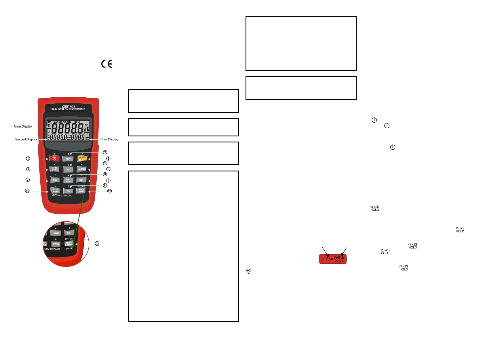
OPERATING INSTRUCTIONS
1. “ ” Power Switch
The “ ” key turns the thermometer on or off. In the
data SET mode, can not power off, must leave data SET
mode then power off.
APO function mode
Pressing “
auto-power function, and the display shows “APO
OFF”.
2. °C/°F Selecting the Temperature Scale
Readings are dual displayed in either degrees Celsius(°C) or degrees Fahrenheit(°F). When the thermometer is turned on, it is set to the temperature scale
that was in use when the thermometer was last turned
off. To change the temperature scale, press the °C/°F
key.
3.
Press the key to enter the Data Hold mode, the
“HOLD” annunciator is displayed. When HOLD mode
is selected, the thermometer held the present readings
and stops all further measurements. Press the
again to cancel HOLD mode causing thermometer to
resume taking measurements. In the MIN/MAX re-
2
cording mode, press
Press
recorded reading is not erased).
Backlight function mode
Pressing the
on and pressing the button again over two seconds to
turn off the backlight. The backlight will switch-off
automatically after 30 seconds.
4. T1 T2/T1-T2 Main display Input Selection
The input selection indicates which input is selected
for main display; T1 thermocouple, T2 thermocouple or
the difference between the two thermocouples (T1-T2),
when the thermometer is turned on, it is set to T1, when
main display input selected T1, then T1 input can select
” power key > 6 seconds to disable
Button (only Main display)
key to stop the recording.
key again to resume recording. (Previously
button over two seconds to turn
key
Page 2

alternate of thermocouple by pressing K/J key switch.
5.
K/J Main display Input Thermocouple Type Select
The K/J key switches the T1 input to select the
K-type or J-type thermocouple as input, when main display input selected T1. When the thermometer is turned
on, it is set to the type selected that was in use when the
thermometer was last turned off.
6. MIN MAX with Time record mode
(only Main display)
Press MIN MAX key to enter the MIN MAX recording mode, (displays the Maximum reading with
time, Minimum reading with time and Average reading
stored in recording mode). In the this mode the automatic power-off feature is disabled and
key, REL key, SET key, Hi/Lo Limits key and main
display T1 T2 T1-T2 key, K/J key are disabled. The
beeper emits a tone when a new minimum or maximum
value is recorded.
Push MIN MAX key to cycle through the MAX,
MIN and AVG readings. If an overload is recorded, the
averaging function is stopped. In this mode, press
HOLD key to stop the recording of readings, all values
are frozen, press again to restart recording.
To prevent accidental loss of MIN, MAX and AVG
data, in this mode can only be cancelled by pressing and
hold down the MIN MAX key for 2 seconds to exit and
erased recorded readings.
key, °C/°F
7. REL Relative mode (only Main display)
Press REL key to enter the Relative mode, zero the
display, and store the displayed Reading as a reference
value and annunciator REL is displayed. Press REL key
again to exit the relative mode. The relative value can
also be entered by the user. (See “SET mode” later in
this manual). When the desired Relative value has been
entered, press REL key to enter the Relative mode,
press SET key use set Relative value as a reference
value. Press REL key again to exit the relative mode. In
the Relative mode, the value (can not >±3000.0 counts)
shown on the LCD is always the difference between the
stored reference and the present reading.
8. Sec. Minu. Selecting the Time scale
Read the third displayed (Time) in either second or
minute. When the thermometer turned on, it is set to
second. To change the Time scale, press sec. Minu. key.
Maximum Time reading is 100 hours. If 100 hours is
exceeded, reset Time to zero and restart.
9. SET mode (Relative value set, Time set and
Hi/Lo Limits value set)
9.1 Press SET key to enter Relative values SET mode
(Press ENTER key can escape relative values set
mode), REL set mode. = = = =.= is displayed in
main display. Relative value is entered via overlay
numbers, then press overlay ENTER key, stored the
relative value, enter Time set mode.
9.2 Time set mode, (Press ENTER key can escape Time
set mode) =.= = = : = = is displayed in second and
third display. Time (hours, minutes, seconds) value
is entered via overlay numbers, then press overlay
ENTER key. Time starts from set time value, enter
Hi/Lo Limits value set mode.
9.3 Hi Limit value set mode,
ENTER key can escape Hi Limit value set mode), =
= = =.= is displayed in main display, Hi Limit value
is entered via overlay numbers, then press overlay
ENTER key, stored the Hi Limit value, enter Lo
Limit value set mode (Press ENTER key can escape
Lo Limit value set mode). = = = =.= is displayed in
main display, Lo Limit value is entered via overlay
numbers, then press overlay ENTER key, stored the
Lo Limit value and exit SET mode.
9.4 When the thermometer is turned on. The Relative
set value and Hi/Lo Limits set value that was in use
when thermometer was last turned off set values.
is displayed (Press
10. T1/T2 T1-T2 second display Input Selection
The input selection indicates which input is selected
for second display; T1 thermocouple, T2 thermocouple
or the difference between the two thermocouples
(T1-T2), when the thermometer is turned on, it is set to
T2 input can select alternate of thermocouple by second
display K/J key switch.
11.
K/J Second display Input thermocouple type select
The K/J key switches the T2 input to select the
K-type or J-type thermocouple as input, when second
display input selected T2. When the thermometer is
turned on, it is set to the type selected that was in use
when the thermometer was last turned off.
12. Hi/Lo Limits mode (only Main display)
Press Hi/Lo Limits key to enter the Hi/Lo Limits
comparative mode,
perature value exceed Hi or Lo Limits value. The beeper
emits a continuity pulse tone, press Hi/Lo Limits key
again to exit the Hi/Lo Limits mode.
is displayed. When input tem-
13. WIRELESS MODE: (802W/802UW)
Pressing key over two seconds to start wireless
function and pressing
to stop wireless function. The wireless mode will shunt
down if there is no wireless signal for two minutes.
SET CH/ID to 00,00, pressing Hi/Lo Limits key and
power key over six seconds when the meter shuts
down sand then the meter will set channel and ID to
00,00 status. The second display will appear 00, which
means that the channel and ID has been set to 00.
again for another two seconds
OPERATOR MAINTENANCE
To avoid possible electri cal shock, disconnect the
thermocouple connectors from the thermometer before
Battery Replacement
1. Power is supplied by 4pcs 1.5V (SIZE AAA) UM-4
R03.
2. The “
ment is needed. To replace battery remove screw from
back of meter and lift off the battery cover.
3. Remove the battery from battery contacts and replace.
4. When not use for long time remove battery.
5. Don’t keep in place with high Temp, or high humidity.
” appears on the LCD display when replace-
Cleaning
Periodically wipe the case with a damp cloth and deter-
gent, do not use abrasives or solvents.
*Software operation manual is in the software disk.
WARNING
removing the cover.
V1. 071607
 Loading...