

Page 1

I
CFI-S86
High Performance
Socket478B Motherboard
User’s Guide
Page 2

II
Edition 1.01
© 2002 CHYANG FUN INDUSTRY CO., LTD.
P/N: 155100-8970
WARNING
To make the system work normally, please ensure JBAT1 of the mainboard is set as below.
Refer to Fig. 2.1 in this manual for the location JBAT1.
JBAT1
1 2 3
If JBAT1 is shorted to 2-3, no CMOS data can be retained.
CAUTION
The motherboard is an electrostatic sensitive device. Don’t open or handle except at a staticfree workstation.
If you use 1.4 GHz CPU or above, please ensure to select the Fan that is able to cool the CPU
down.
Windows, MS-DOS, and MS Word are trademarks of Microsoft Corporation.
Novell, Netware are trademarks of Novell, Inc.
Lotus, 1-2-3 and Symphony are trademarks of Lotus Development Corporation.
Page 3

III
PC, AT, PC-DOS, OS/2 and Presentation Manager are trademarks of IBM Corporation.
UNIX is the trademark of AT&T.
All other brand and product names are trademarks or registered trademarks of their respective
companies.
The information presented in this publication has been carefully checked for reliability;
however, no responsibility is assumed for inaccuracies, whereas, specification is subjected to
change without notice.
Page 4

IV
CONTENTS
CHAPTER 1 INTRODUCTION1
CHAPTER 2 JUMPER SETTINGS
2.1 Jumper Presentation
2.2 Graphical Description of Jumper Settings
2.3 Clear CMOS Data
2.4 CPU Frequency Setting
2.5 Factory Setting
CHAPTER 3 CONNECTOR CONFIGURATI ON
3.1 U1 - Socket478
3.2 FAN Connectors
3.3 J12 - Multiple Function Jumper
3.4 JCDIN1 - CD-IN Connector
3.5 CN4 - ATX 12V Connector
3.6 ATX Power Supply Connector
3.7 Rear Panel Connectors
3.8 Front Panel Connectors
CHAPTER 4 AWARD BIOS DESCRIPTION
4.1 Entering Setup
4.2 Standard CMOS Features Setup
4.3 Advanced BIOS Features Setup
4.4 Advanced Chipset Features Setup
4.5 Integrated Peripherals Setup
4.6 Power Management Setup
4.7 Pnp/PCI Configuration
4.8 PC Health Status
4.9 Frenquency/Voltage Control
4.10 Password Setting
4.11 Exit Setup
4.11 Boot with BIOS Defaults
APPENDIX A QUICK GUIDE
1
3 3 3 4 4 4
5 5 5 5 5 5 6 6 6
7 7 8 9 10 12 13 15 16 16 17 18 18
19
Page 5

1
CHAPTER 1 INTRODUCTION
Preface
CFI-S86 is a 6-layers, Flex-ATX form factor, high -performance Socket478 motherboard. The
system core logic is based on VIA P4M266 Chipsets. It is integrated with NEC
uPD720100AGM USB 2.0 controller and Realtek RTL8100B Ethernet controller.
Features
CPU:
?? Support Intel Socket 478 Pentium 4 processor
Chipset:
?? VIA P4M266 chipsets
?? Winbond W83627HF LPC controller
?? Realtek RTL8100B Ethernet controller
?? NEC uPD720100AGM USB 2.0 controller
Architecture:
?? IBM PC and PCI 2.1/2.2 compatible
?? 400MHz Quad-pumped Front Side Bus
Main Memory:
?? Two 184-pin DIMM sockets
?? Support DDR200/266 SDRAM up to 2GB
VGA:
?? Integrated S3 ProSavage8 Graphics controller in North Bridge
?? Support 3D/2D enhancements
?? Support AGP8X bandwidth. Max. Bandwidth 2.1GB/sec
?? VT1621 TV Encoder, TV-out supported
Audio:
?? AC-Link with AC’97 2.2 compliant
?? Software audio with VT1612A 4-channel AC’97 codec
USB 2.0:
?? NEC uPD720100AGM USB 2.0 controller
?? Compliant with USB 2.0 specification
?? Support Hi-speed, Full-speed and Low-speed data transfer rate. Max. Bandwidth
480Mbits/s
?? The USB 2.0 driver supported
Page 6

Chapter 1
2
Ethernet:
?? Realtek RTL8100B 10/100Base-T Ethernet controller
?? Full-Duplex supported
?? WFM 2.0 compliant
I/O Interface:
?? Winbond W83627HF LPC controller
?? Two enhanced PCI IDE channels which support up to 4 IDE devices with ATA-133
transfers up to 133MB/sec
?? Build in FDC supports 1.2M/1.44M/2.88M FDD
Back Panel I/O Output:
?? PS/2 mouse and keyboard connectors
?? 2 Type A USB connectors, 1 RJ-45 LAN port
?? 1 S connector, 1 Composite connector
?? 2 fast serial ports, 1 D-type 15-pin VGA connector
?? Line-in, MIC-in, Speaker-out
System BIOS:
?? Award BIOS with 2MB EEPROM
?? Built-in Trend? ChipAway Anti-Virus Program
?? ACPI/PnP supported
Expansion Slots:
?? 1 PCI slot, 1 AGP4X slot
Form Factor:
?? Flex -ATX @ 262 mm (L) × 180 mm (W), 6 Layers
Front Panel I/O Output Board:
?? 1 IR port, IrDA 1.0/FIR supported
?? 2 Type A USB connectors, 1 PS/2 mouse connector
?? Line-in, MIC-in, Speaker-out, Game port and Volume control
?? Board size @ 30 mm (L) x 180 mm (W)
Page 7
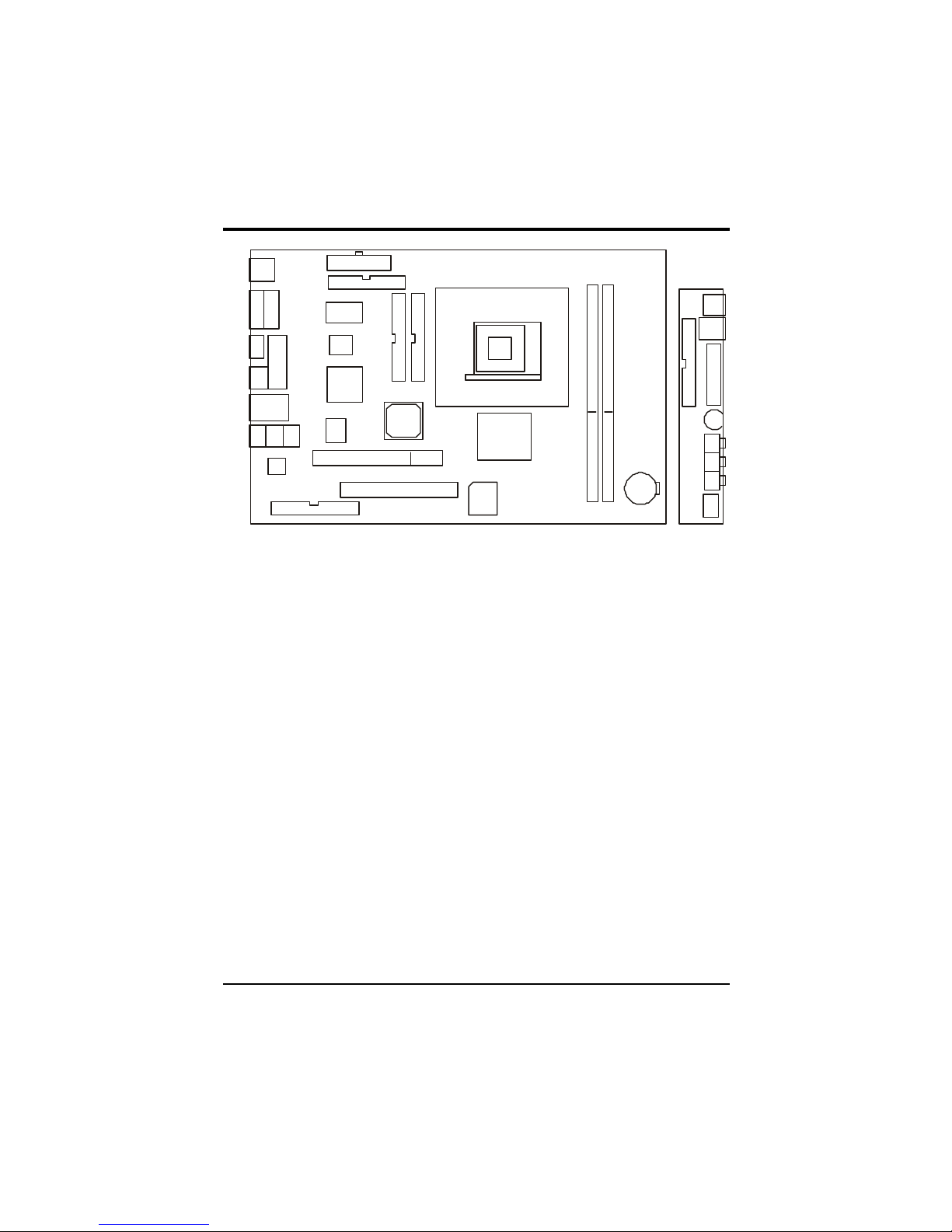
Connector Configuration
3
ATX POWER
FDD1
W83627HF
VIA8233
VIA
P4M266
AGP
ID E1
ID E2
NEC
USB 2.0
RTL8100B
DIMM1
DIMM2
BATTERY
PCI
GAME1
KBMS1
USB1
MPGA478B
KBMS1
USB/LAN
39SF020A
COM1
COM2
V-Video
S-Video
VGA
LINE LINE MIC
OUT IN IN
AC97 CODEC
VT1621
VOLIrDA
40-pin Conn
40-pin Conn
SPK LINE MIC
OUT IN IN
Fig. 1.1 Key Components of the Motherboard
Page 8

Page 9
5
CHAPTER 2 JUMPER SETTINGS
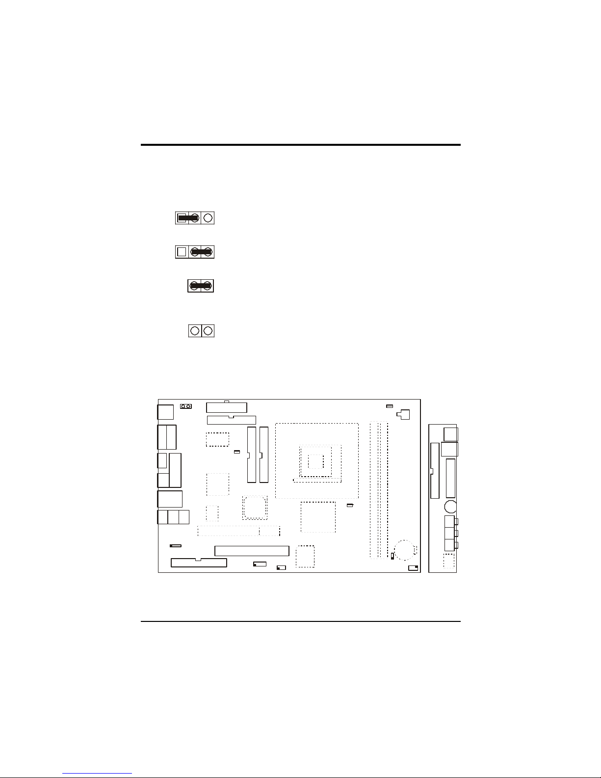
2.1 JUMPER PR ESENTATION
Pins 1 and 2 are shorted with a jumper cap.
1 2 3
Pins 2 and 3 are shorted with a jumper cap.
1 2 3
The jumper is shorted when the jumper cap is placed over the
two
pins of the jumper.
The jumper is opened when the cap is removed from jumper.
2.2 GRAPHICAL DESCRIPTION OF JUMPER
SETTINGS
KBMS1
USB/LAN
COM1
COM2
V-Video
S-Video
VGA
GAME1
KBMS1
USB1
LINE LINE MIC
OUT IN IN
12V Conn.
FAN3
JBAT1
J12
FAN1
FAN2
ATX POWER
FDD1
AGP
ID E1
ID E2
JCDIN1
J18
SW1
SW2
VOL
40-pin Conn
40-pin Conn
SPK LINE MIC
OUT IN IN
Fig. 2.1 Jumper /Connector Location of the mainboard
Page 10
Chapter 2
6
2.3 CLEAR CMOS DATA
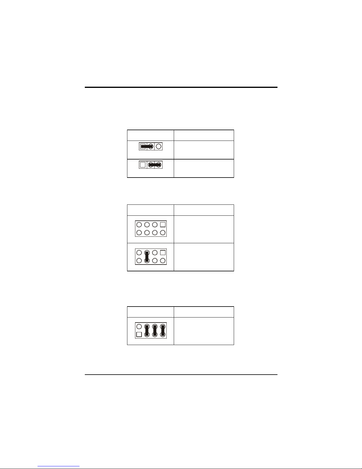
JBAT1 is used to clear the CMOS Data in the RTC (build in ICH chip).
JBAT1 Description
1
Normal
1
Clear CMOS
2.3 CPU FREQUENCY SETTING
SW2 Description
4 3 2 1
5 6 7 8
133MHz
4 3 2 1
5 6 7 8
100MHz
Note: P4M266 only support 100MHz * 4 Front Side Bus, SW2 must set at [3,6].
2.4 FACTORY SETTING
SW1 Description
1 2 3 4
8 7 6 5
SB Default
Note: SW1 is SB default setting, cannot be changed.
Page 11

7
CHAPTER 3 CONNECTOR
CONFIGURATION
Once the mainboard has been fastened into system case, the next step is to connect the internal
cables. The internal cables are wire leads with plastic female connectors that attach to the
connectors. The mainboard connectors have the various numbers of pins and are the contact
points between the mainboard and other parts of the computer.
Refer to Fig. 2.1 for the location of the connectors.
3.1 U1 – SOCKET478
U1 is the Socket478 CPU socket which can support Intel Pentium 4 processor.
3.2 FAN CONNECTORS
FAN1, FAN2, FAN3 are fan connectors of case or CPU.
J18 is a +12V Case FAN Connector.
3.3 J12 – MULTIPLE FUNCTION JUMPER
J12 is a front panel multi-function jumper. The pin definition is as following figure.
1
+
+
NC
NC
NC
POWER
LED
HDD LED
POWER
SWITCH
RESET
3.4 JCDIN1 – CD-IN CONNECTOR
Page 12
Chapter 3
8
3.5 CN4 – ATX 12V Connector
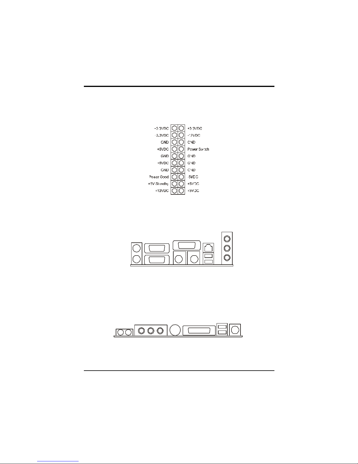
3.6 ATX POWER SUPPLY CONNECTOR
1 11
3.7 Rear Panel Connector
CN1 and CN2 is the V-port and S-port of Video connector.
COM
COM
VGA
USB
MOUSE
KEYBOARD
LAN
SPK OUT
LINE IN
MIC IN
V-Port S-Port
3.8 Front Panel Connector
VOL is the volume knob.
IrDA is an infrared transceiver module.
GAME
USB
MOUSE
LINE LINE MIC
OUT IN IN
VOL
IrDA
Page 13

9
CHAPTER 4 AWARD BIOS
DESCRIPTION
4.1 ENTERING SETUP
Power on the computer, when the following message briefly appears at the bottom of the
screen during the POST (Power On Self Test), press <Del> key or simultaneously press the
<Ctrl> + <Alt> + <Esc> keys, to enter the AWARD BIOS CMOS Setup Utility.
Press <Del> to enter SETUP
Once you have entered, the Main Menu (Fig. 4.1) appears on the screen. The main menu
allows you to select from eleven setup functions and two exit choices. Use the arrow keys to
select the item and press <Enter> to accept or enter the sub-menu.
Phoenix – AwardBIOS CMOS Setup Utility
?Standard CMOS Features
?Advanced BIOS Features
?Advanced Chipset Features
?Integrated Peripherals
?Power Management Setup
?PnP/PCI Configurations
?PC Health Status
?Frequency/Voltage Control
Load Fail – Safe Defaults
Load Optimized Defaults
Set Supervisor Password
Set User Password
Save & Exit Setup
Exit Without Saving
Esc: Quit F9: Menu in BIOS ????: Select Item
F10: Save & Exit Setup
Load Optimized Defaults
Load Optimized Defaults
The Optimized Defaults are common and efficient. It is recommended to load the optimized
defaults at first, and then modify the needed configuration settings.
Page 14

Chapter 4
10
4.2 STANDARD CMOS FEATURES SETUP
Use the arrow keys to highlight the item, and then use the <PgUp> or <PgDn> to select the
value desired in each item.
Phoenix – AwardBIOS CMOS Setup Utility
Standard CMOS Features
Item Help
Date (mm:dd:yy)
Time (hh:mm:ss)
? IDE Primary Master
? IDE Primary Slave
? IDE Secondary Master
? IDE Secondary Slave
Drive A
Drive B
Video
Hal On
Select Display Device
Select TV mode
Base Memory
Extended Memory
Total Memory
Tue. Jan 01 2002
11:23:33
[1.44M, 3.5 in.]
[None]
[EGA/VGA]
[All, But Keyboard]
[CRT]
[NTSC]
640K
63488K
64512K
Menu Level ?
Change the day,
month, year and
century
????:Move Enter:Select +/-/PU/PD:Value F10:Save ESC:Exit F1:General Help
F5: Previous Values F6: Fail - Save Defaults F7: Optimized Defaults
Data: Set the day, month, year and century.
Time: Set the internal clock.
IDE Primary/Secondary Master/Slave: Press Enter to enter the detail settings of hard drive.
IDE HDD Auto-Detection: Press Enter to detect the HDD’s status automaticly.
IDE Primary Slave: Auto, Manual, None
Access Mode: Auto, CHS, LBA, Large
Drive A/B: Set the floppy drive type. None; 350K, 5.25in; 1.2M,5.25in.; 720K, 3.5in.;1.44M,
3.5in.;2.88M, 3.5in
Video [EGA/VGA]
Select the type of video display card installed in your system.
EGA/ VGA: For EGA, VGA, SEGA, SVGA, or PGA monitors adapters.
Page 15

Award BIOS Description
11
CGA 40: Color Graphic Adapter, powering up in 40-column mode.
CGA 80: Color Graphic Adapter, powering up in 80-column mode.
MONO: Monochrome adapter, including high-resolution monochrome adapters.
Halt On [All, But Keyboard]
This field determines whether the system will stop if an error is detected during powering up.
All errors: Stop and prompt whenever the BIOS detect a non-fatal error.
No errors: The system boot will not stop for any error that may be detected.
All, But Keyboard: Stop and prompt for all other errors but a keyboard error.
All, But Diskette: Stop and prompt for all other errors but a diskette error.
All, But Disk/Key: Stop and prompt for all other errors but a keyboard or disk error.
Select Display Device: CRT, TV, CRT+TV, AUTO
Select TV mode: NTSC, PAL
Memory: This field displays the amount of memory detected during the boot process.
4.3 ADVANCED BIOS FEATURES
Phoenix – AwardBIOS CMOS Setup Utility
Advanced BIOS Features
Item Help
Virus Warning
CPU L1 & L2 Cache
CPU L2 Cache ECC Checking
Quick Power On Self Test
First Boot Device
Second Boot Device
Third Boot Device
Boot Other Device
Swap Floppy Drive
Boot Up Floppy Seek
Boot Up Numlock Status
Typematic Rate Setting
* Typematic Rate (Chars/Sec)
* Typematic Delay (Msec)
Security Option
OS Select For DRAM > 64MB
Video BIOS Shadow
Small Logo(EPA) Show
[Disabled]
[Enabled]
[Enabled]
[Enabled]
[Floppy]
[HDD – 0]
[LS120]
[Enabled]
[Disabled]
[Enabled]
[On]
[Disabled]
6
250
[Setup]
[Non – OS2]
[Enabled]
[Disabled]
Menu Level ?
Allows you to choose
the VIRUS warning
feature for IDE Hard
Disk boot sector
protection. If this
function is enabled and
someone attempt to
write data into this area,
BIOS will show a
warning message on
screen and alarm beep
????:Move Enter:Select +/-/PU/PD:Value F10:Save ESC:Exit F1:General Help
F5: Previous Values F6: Fail - Save Defaults F7: Optimized Defaults
Page 16

Chapter 4
12
Virus warning: Allows you to choose the VIRUS warning feature for IDE hard disk boot
sector protection. If it is enabled and someone attempt to write data into the sector, BIOS will
show a warning message on screen and alarm beep. Enabled, Disabled
CPU L1 & L2 Cache Enabled, Disabled
CPU L2 Cache ECC Checking Enabled, Disabled
Quick Power On Self Test: Allows the system to skip some tests while booting. Disabled is
Normal POST. Enabled, Disabled:
First (Second, Third) Boot Device: Select Your Boot Device Priority.
Floppy, LS120, HDD-0, SCSI, CD-ROM, HDD-1, HDD-2, HDD-3, ZIP100, LAN, Disabled.
Boot Other Device: Enable boot from other device.
Swap Floppy Drive If the system have two floppy drives, choose Enabled to assign physical
drive B to logical drive A and vice-versa. Disabled, Enabled
Boot Up Floppy Seek: Tests the tracks of floppy drives to determine whether they have 40 or
80 tracks. Enabled, Disabled
Boot Up NumLock Status: Selects power on state for NumLock. On, Off
Typematic Rate Setting: Keystrokes repeat at a rate determined by the keyboard controller,
When enabled, you can configure the following two items. Enabled, Disabled
Typematic Rate (chars/sec):The rate at which character repeats when you hold down a key.
Typematic Delay (Msec): The delay before keystrokes begin to repeat.
Security Option: Determine whether the password is required every time the system boots or
only when you enter setup. Setup, System
OS Select For DRAM>64MB: Selects OS2 only if you are running OS/2 operating system
with more than 64MB RAM. Non-OS2, OS2
Video BIOS Shadow Enabled copies Video BIOS to shadow RAM to improves performance.
Enabled, Disabled
Small Logo(EPA) show: Disabled, Enabled
4.4 ADVANCED CHIPSET FEATURES SETUP
Phoenix – AwardBIOS CMOS Setup Utility
Advanced Chipset Features
Page 17

Award BIOS Description
13
Item Help
?DRAM Clock/Drive Control
?AGP & P2P Bridge Control
?CPU & PCI Bus Control
Memory Hole
System BIOS Cacheable
Video RAM Cacheable
Delay Prior to Thermal
VGA Share Memory Size
FB Address Conversion
FB Page Close Prediction
[Press Enter]
[Press Enter]
[Press Enter]
[Disabled]
[Disabled]
[Disabled]
[16 Min]
[32M]
[Enabled]
[Enabled]
Menu Level ?
????:Move Enter:Select +/-/PU/PD:Value F10:Save ESC:Exit F1:General Help
F5: Previous Values F6: Fail - Save Defaults F7: Optimized Defaults
DRAM Clock/Drive Control: Press <Enter> to enter the submenu.
DRAM Clock: By SPD, 100MHz, 133MHz
DRAM Timing: By SPD, Manual.
When choose “Manual”, the following six items will display.
SDRAM CAS Latency: 2, 2.5
Bank Interleave: Disabled, 2 Bank, 4 Bank
Precharge to Active(Trp): 3T, 2T
Active to Precharge(Tras): 6T, 5T
Active to CMD(Trcd): 3T, 2T
DRAM Command Rate:2T Command, 1T Command
DRAM Burst Len: 4, 8
CPU read DRAM Mode: Fast, Medium, Slow
AGP & P2P Bridge Control: Press <Enter> to enter submenu. Default setting is
recommended.
AGP Aperture Size: 64M, 32M, 16M, 8M, 4M, 256M,128M
AGP Mode: 4X, 2X, 1X
AGP Driving Control: Auto, Mnaual
When choose Manual, the following one item can be modified.
AGP Driving Value: DA, 00~FF
AGP Fast Write: Disabled, Enabled
AGP Master 1WS Write: Disabled, Enabled
AGP Master 1 WS Read: Disabled, Enabled
CPU & PCI Bus Control: Press <Enter> to enter submenu
CPU to PCI Write Buffer: Enabled, Disabled
PCI Master 0 WS Write: Enabled, Disabled
PCI Delay Transaction: Disabled, Enabled
Memory Hole Set the memory hole reserved for expanded ISA card. Disabled, 15M-16M
Page 18

Chapter 4
14
System BIOS Cacheable: Besides conventional memory, the system BIOS area is also
cacheable. Enabled, Disabled:
Video RAM Cacheable: Besides conventional memory, video RAM area is also cacheable.
Enabled, Disabled
Delay Prior to Thermal: 16 Min, 32 Min, 4 Min, 8 Min
VGA Share Memory Size: 32M, Disabled, 8M, 16M
FB Address Conversion: Enabled, Disabled
FB Page Close Prediction: Enabled, Disabled
Page 19

Award BIOS Description
15
4.5 INTEGRATED PERIPHERALS
Phoenix – AwardBIOS CMOS Setup Utility
Integrated Peripherals
Item Help
?VIA OnChip IDE Device
?VIA OnChip PCI Device
? SuperIO Device
Init Display First
USB Keyboard Support
IDE HDD Block Mode
[Press Enter]
[Press Enter]
[Press Enter]
[PCI Slot]
[Disabled]
[Enabled]
Menu Level ?
????:Move Enter:Select +/-/PU/PD:Value F10:Save ESC:Exit F1:General Help
F5: Previous Values F6: Fail - Save Defaults F7: Optimized Defaults
VIA OnChip IDE Device: Press <Enter> to enter submenu.
OnChip IDE Channel0/1: Enabled, Disabled
IDE Prefetch Mode: Enabled, Disabled
Primary/Secondary Master/Slave PIO: Auto, Mode 0~4
Primary/Secondary Master/Slave UDMA: Auto, Disabled
VIA OnChip PCI Device: Press <Enter> to enter submenu.
VIA -3058 AC97 Audio: Auto, Disabled
VIA –3068 MC97 Modem: Auto, Disabled
Supper IO Device: Press <Enter> to enter submenu.
Onboard FDC Controller: Enabled, Disabled
Onboard Serial Port 1/2: Defines the onboard serial port address and IRQ number. 3F8/IRQ4,
2F8/IRQ3, 3E8/IRQ4, 2E8/IRQ3, Auto, Disabled.
UART Mode Select: Normal, IrDA, ASKIR
RxD, TxD Active: Hi,Lo; Lo,Hi; Lo,Lo; Hi,Hi
IR Transmission Delay: Enabled, Disabled
UR2 Duplex Mode: Half, Full
Use IR Pins: IR-Rx2Tx2; RxD2,TxD2
Onboard Parallel Port: Defines onboard parallel port address and IRQ number. 378/IRQ7,
278/IRQ5, 3BC/IRQ7, Disabled.
Parallel Port Mode: SPP, EPP, ECP, ECP+EPP, Normal
EPP Mode Select: EPP1.7, EPP1.9
ECP Mode Use DMA: 3,1
Game Port Address: 201, 209, Disabled
Midi Port Address: Disabled, 330, 300, 290
Midi Port IRQ: 5, 10
Page 20

Chapter 4
16
Init Display First PCI Slot, AGP.
USB Keyboard Support: Support USB Keyboard under DOS status. Disabled, Enabled
IDE HDD Block Mode: . If your IDE hard drive supports block mode, select Enabled for
automatic detection of the optimal number of block read/writes per sector the drive can
support.
Enabled, Disabled.
4.6 POWER MANAGEMENT SETUP
Phoenix – AwardBIOS CMOS Setup Utility
Power Management Setup
Item Help
ACPI Function
Power Management Option
HDD Power Down
Suspend Mode
Video Off Option
Video Off Method
MODEM Use IRQ
Soft – Off by PWRBTN
PWRON After PWR-Fail
? IRQ/Event Activity Detect
[Enabled]
[User Define]
[Disabled]
[Disabled]
[Suspend -> Off]
[V/H SYNC+Blank]
[3]
[Instant – Off]
[Off]
[Press Enter]
Menu Level ?
????:Move Enter:Select +/-/PU/PD:Value F10:Save ESC:Exit F1:General Help
F5: Previous Values F6: Fail - Save Defaults F7: Optimized Defaults
ACPI function Enabled, Disabled.
Power Management Option:
User Define: Users can configure their own Power Management Timer.
Min Saving - defined timer values are used. All timers are in their MAX values.
Max Saving - defined timer values are used. All timers are in their MIN values.
HDD Power Down
Disabled: HDD’s motor will not be off by timer.
1 - 15 Min: Set the HDD idle time before the HDD enters power saving mode (motor off).
Suspend Mode
Disabled: The system never enters Suspend mode by timer.
1 Min ~ 1Hr: Defines the continuous idle time before the system enters Suspend mode. If any
items defined in “PM Events” are on and activated, the system will be woken up.
Page 21

Award BIOS Description
17
Video Off Option Suspend -> Off, MODEM Use IRQ, Always On
Video Off Method
V/H SYNC+Blank: In addition to Blank Screen, BIOS will also turn off the V-SYNC & H –
SYNC signals from VGA card to monitor.
DPMS Support: This function is enabled only for VGA cards supporting DPMS.
Blank Screen: The system BIOS will only blank off the screen when disabling video.
Note: When the green monitor does not detect the V/H-SYNC signals, the electron gun will be
turned off.
MODEM Use IRQ: Special wake-up event for Modem. 3, 4, 5, 7, 9, 10, 11 NA.
Soft-Off by PWRBTN
Instant-Off The system will immediately power off once the power button is pressed.
Delay 4 sec The system will power off when power button is pressed for 4 seconds.
IRQ/Event Activity Detect: Press Enter to <enter> submenu.
VGA: OFF, ON
LPT & COM: LPT/COM, NONE, LPT, COM
HDD & FDD: ON, OFF
PCI Master: OFF, ON
PowerOn by PCI Card: Disabled, Enabled
Wake Up On LAN/Ring: Disabled, Enabled
RTC Alarm Resume: Disabled, Enabled
When choose Enabled, the following two items can be modified.
Date (of Month): 0~31
Resume Time (hh:mm:ss): 00: 00 : 00
IRQs Activity Monitoring: Press <Enter> to enter submenu.
Primary INIR: ON, OFF.
When choose ON, the following items can be set to Disabled or Enabled.
IRQ3 (COM 2)
IRQ4 (COM 1)
IRQ5 (LPT 2)
IRQ6 (Floppy Disk)
IRQ7 (LPT 1)
IRQ8 (RTC Alarm)
IRQ9 (IRQ2 Redir)
IRQ10 (Reserved)
IRQ11 (Reserved)
IRQ12 (PS/2 Mouse)
IRQ13 (Coprocessor)
IRQ14 (Hard Disk)
IRQ15 (Reserved)
Page 22

Chapter 4
18
Page 23

Award BIOS Description
19
4.7 PNP/PCI CONFIGURATION SETUP
Phoenix – AwardBIOS CMOS Setup Utility
PnP/PCI Configuration
Item Help
PNP OS Installed
Reset Configuration Data
Resources Controlled By
*IRQ Resource
PCI/VGA Palette Snoop
Assign IRQ For VGA
Assign IRQ For USB
INT Pin 1 Assignment
INT Pin 2 Assignment
INT Pin 3 Assignment
INT Pin 4 Assignment
[No]
[Disabled]
[Auto (ESCD)]
Press Enter
[Disabled]
[Enabled]
[Enabled]
[Auto]
[Auto]
[Auto]
[Auto]
Menu Level ?
????:Move Enter:Select +/-/PU/PD:Value F10:Save ESC:Exit F1:General Help
F5: Previous Values F6: Fail - Save Defaults F7: Optimized Defaults
PNP OS Installed: Select Yes if you are using a Plug and Play capable operation system;
Select No if you need the BIOS to configure non-boot devices. No, Yes
Reset Configuration Data: Default is Disabled. Select Enabled to reset ESCD when you exit
Setup if you have installed a new add-on and the system reconfiguration has caused such a
serious conflict that the OS cannot boot. Enabled/ Disabled
Resources Controlled By BIOS can automatically configure all the boot and PnP compatible
devices. If you choose Auto, you cannot select IRQ DMA and memory base address fields,
because BIOS automatically assigns them. Auto(ESCD), Manual.
PCI/VGA Palette Snoop Disabled is default setting. Enabled Non-standard VGA cards such
as graphics accelerators or MPEG video cars may not show colors properly. Enabling this item
can solve this problem.
Assign IRQ For VGA/USB: Enabled, Disabled
INT Pin 1/2/3/4 Assignment: Auto, 3, 4, 5, 7, 9, 10, 11, 12, 14, 15
Page 24

Chapter 4
20
4.8 PC HEALTH STATUS
Phoenix – AwardBIOS CMOS Setup Utility
PC Health Status
Item Help
CPU Warning Temperature [Disabled]
Current System Temp.
Current CPU1 Temperature
Current CPUFAN1 Speed
Current CPUFAN2 Speed
Current CPUFAN3 Speed
IN0 (V)
IN1 (V)
IN2 (V)
+5 V
+12 V
-12 V
-5 V
UBAT (V)
5VSB (V)
Shutdown Temperature [Disabled]
Menu Level ?
????:Move Enter:Select +/-/PU/PD:Value F10:Save ESC:Exit F1:General Help
F5: Previous Values F6: Fail - Save Defaults F7: Optimized Defaults
CPU Warning Temperature: Enabled an beep alarm when the CPU temperature is over this
value. Disabled,.Enabled
Shutdown Temperature Set the shutdown temperature.
4.9 FREQUENCY/VOLTAGE CONTROL
Phoenix – AwardBIOS CMOS Setup Utility
Frequency/Voltage Control
CPU Clock Ratio
[8 X]
Item Help
Page 25

Award BIOS Description
21
Menu Level ?
????:Move Enter:Select +/-/PU/PD:Value F10:Save ESC:Exit F1:General Help
F5: Previous Values F6: Fail - Save Defaults F7: Optimized Defaults
CPU CLOCK Ratio: Selects the multiplication of processor core frequency. If a Ratio locked
processor installed, this item will be hidden. This item is only for users who understand all the
CPU parameters, i.e. system bus frequency, “66MHz” and multiplication of processor core
frequency for system bus frequency “x3, x3.5, x4, x4.5, x5, x5.5, x6, x6.5, x7, x7.5, x8”. Selects
the CPU speed according to your CPU brand and type. 8X~49X,
Auto detect DIMM/PCI Clk Enabled Close empty DIMM or PCI clock to reduce EMI.
Disabled Does not close empty DIMM or PCI clock.
Warning: Be sure your selection is right. CPU over speed will be dangerous!
Spread spectrum: Disabled, Enabled
CPU Host/AGP/PCI Clock:
Default, 100/66/33Mhz, 102/68/34Mhz, 105/70/35Mhz, 108/72/36Mhz, 114/76/38Mhz,
117/78/39Mhz, 120/80/40Mhz.
4.10 PASSWORD SETTING
When you select “Set User Password” or “Set Supervisor Password” and press Enter, the
following message will appear at the center of the screen:
ENTER PASSWORD
Type the password, up to eight characters, and press Enter. The password typed now will
clear any previously entered password from CMOS memory. You will be asked to confirm the
password. Type the password again and press Enter. You may also press Esc to abort the
selection.
To disable password, just press Enter when you are prompted to enter password. A message
as below will confirm the password being disabled. Once the password is disabled, the system
will boot and you can enter BIOS Setup freely.
PASSWORD DISABLED
If you have selected “Syste m” in “Security Option” of “BIOS Features Setup” menu, you will
be prompted for the password every time the system reboots or any time you try to enter
BIOS Setup.
If you have selected “Setup” at “Security Option” from “BIOS Features Setup” menu, you
Page 26

Chapter 4
22
will be prompted for the password only when you enter BIOS Setup.
Supervisor Password has higher priority than User Password. You can use Supervisor
Password when booting the system or entering BIOS Setup to modify all settings. Also you
can use User Password when booting the system or ent ering BIOS Setup but can not modify
any setting if Supervisor Password is enabled.
Page 27

Award BIOS Description
23
4.11 EXIT SETUP
Save & Exit Setup
After finish modifying the values, choose this item to save the changes to the CMOS RAM. A
confirmation message will appear, type “Y” and press Enter to save and exit Setup.
Exit Without Saving
If you do not want to save the changes, choose this item to exit Setup without saving changes.
A confirmation message will appear, type “Y” and press Enter to save and exit Setup.
4.12 BOOT W ITH BIOS DEFAULTS
If you have made all the changes to CMOS values and the system cannot boot with the CMOS
values selected in setup, clear CMOS after power-down, then power on again. System will
boot with BIOS default settings.
Page 28

Page 29

25
APPENDIX A QUICK GUIDE
The table below summaries the functions and settings of each jumper of the motherboard.
Function Jumper Settings
Normal JBAT1 1-2
Clear CMOS Data
Clear JBAT1 2-3
133 MHz SW1.2, SW2.3 Open
CPU Frequency
100 MHz SW1.2, SW2.3 Short
 Loading...