

Page 1

KR Series UPS (6-10)KVA
User’s Manual
Page 2

INDEX
1. Safety instruction .......................................................................................................... - 1 -
1.1 Explanation of symbols ................................................................................................... - 1 -
1.2 Safety precautions. ......................................................................................................... - 1 -
2. Overview ........................................................................................................................ - 5 -
2.1 Model Explanation ........................................................................................................... - 5 -
2.2 Abstract of Product .......................................................................................................... - 6 -
2.2.1 Product Feature ..................................................................................................... - 6 -
2.2.2Technical Specifications .......................................................................................... - 8 -
3. Basic Principles and Structure ..................................................................................... - 9 -
3.1 Working Principle of Single unit ....................................................................................... - 9 -
3.1.1Working Principle Diagram ...................................................................................... - 9 -
3.1.2 Working Principle ................................................................................................... - 9 -
3.1.3Working Procedure ............................................................................................... - 10 -
3.2 Parallel System Principle ............................................................................................... - 11 -
3.2.1Working Principle .................................................................................................. - 11 -
3.2.2Working Mode ....................................................................................................... - 11 -
3.3 Machine Structure ................................ ................................ ......................................... - 14 -
3.3.1Display structure ................................................................................................... - 14 -
3.3.2 Display interface................................................................................................... - 14 -
3.3.3 KR6000L, KR(/B)1110, KR(/B)3110 appearance .............................................. - 15 -
3.3.4 KR6000, KR(/B)1110S, KR(/B)3110S appearance ................................................ - 17 -
4. Installation ................................................................................................................... - 19 -
4.1 Installation Notice ...................................................................................................... - 19 -
4.2 Installation process .................................................................................................... - 20 -
4.3 Installation preparation ............................................................................................... - 20 -
4.3.1 Checking the installation site ................................................................................ - 20 -
4.3.2 Unpacking and inspect the machine ................................................................ - 22 -
4.4 Machine Installation ................................................................................................... - 23 -
4.4.1 Machine installation notes ............................................................................... - 23 -
4.5 Check the main input .................................................................................................. - 23 -
4.6 UPS Installation .......................................................................................................... - 23 -
4.6.1 KR (6&10kVA) Series UPS installation ................................................................. - 23 -
4.7 Battery Cabinet Installation ......................................................................................... - 25 -
4.7.1Important Security Regulation ............................................................................... - 25 -
4.7.2 Installation Steps ................................................................................................ .. - 25 -
4.8(Parallel)System installation ....................................................................................... - 26 -
4.9 Electrical connection ................................................................................................... - 26 -
4.9.1 Mode of Single Unit Connection ......................................................................... - 26 -
4.9.2 Wire Connection of Parallel system ...................................................................... - 27 -
Page 3

4.10 System inspection and testing ................................................................................ - 30 -
4.10.1 Check electrical connections .............................................................................. - 30 -
4.10.2 UPS testing ..................................................................................................... - 30 -
4.10.3 Connect with the load ...................................................................................... - 30 -
5. Using and Operation ................................................................................................... - 31 -
5.1 Notes of using UPS ....................................................................................................... - 31 -
5.2 UPS single unit operation process ................................................................................. - 31 -
5.3 Operation instruction ..................................................................................................... - 32 -
5.3.1 Inspection before power on ................................................................ .................. - 32 -
5.3.2 UPS Startup Steps ............................................................................................... - 33 -
5.3.3 Start the load ........................................................................................................ - 33 -
5.3.4 Shutdown UPS ........................................................................................................... - 33 -
5.4. Operation of Parallel system ........................................................................................ - 34 -
5.4.4 Online start-up Parallel System ............................................................................ - 35 -
5.4.5 Redundancy and Expansion of Parallel System ................................................... - 35 -
6. Maintenance and Fault Diagnosis .............................................................................. - 37 -
6.1 Maintenance Guide ....................................................................................................... - 37 -
6.1.1 Safety Precaution ................................................................................................. - 37 -
6.1.2 Periodic Preventative Maintenance ...................................................................... - 37 -
6.2 Battery Daily Maintenance ............................................................................................. - 38 -
6.3 Battery replacement ...................................................................................................... - 38 -
6.4 Fault diagnosis ........................................................................................................... - 39 -
6.4.1 FAQ ..................................................................................................................... - 39 -
6.4.2 Troubleshooting for the failure of single units system and parallel system ............. - 41 -
Appendix A. Packaging Transportation and Storage ........................................................... - 42 -
A.1 Packaging ..................................................................................................................... - 42 -
A.2 Transportation ............................................................................................................... - 42 -
A.3 Storage ......................................................................................................................... - 42 -
Appendix B Table of Toxic and harmful substance in product ........................................... - 43 -
Page 4
KR series(6-10kVA)user’s manual
- 1 -
1. Safety instruction
Summary
This chapter describes the safety symbols and safety precautions. Please read this
chapter carefully before any operation of UPS in order to avoid of unsafe operation
which will endanger personal safety or equipment damage.
1.1 Explanation of symbols
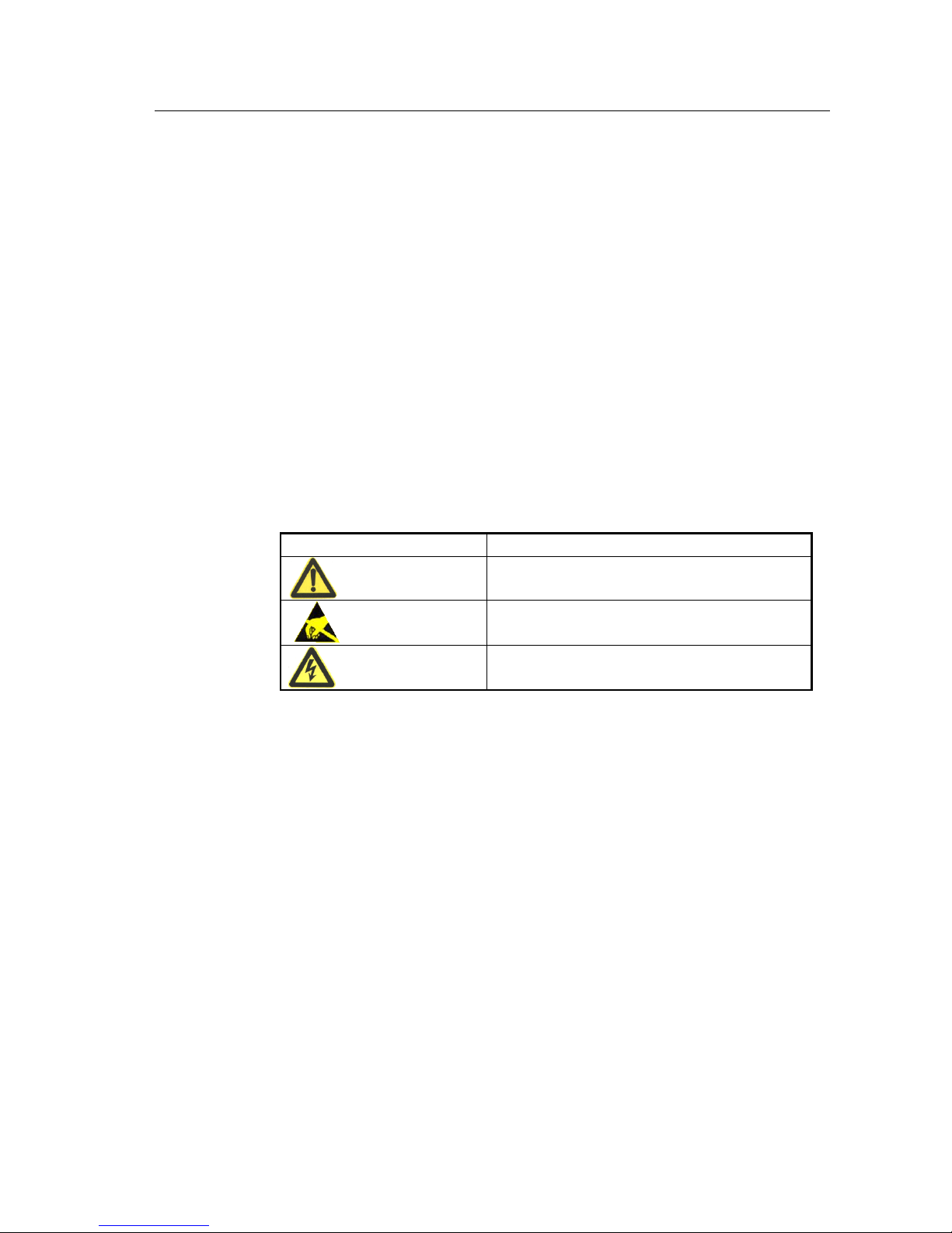
Safety symbols please refer to table 1.1-1, these symbols are used to remind the
reader to abide the safety operation during the installation, operation and
maintenance
Table 1.1-1 Safety symbols and meaning
Safety symbol
meaning
Safety tips
Anti-static tips
Beware of electric shock tips
1.2 Safety precautions.
The UPS internal exists high temperature and voltage, the equipment installation, the operator
must comply with relevant safety standards and operational procedures during UPS installation,
operation and maintenance processing, or it may cause personal injury or equipment damage.
The safety precautions mentioned in the user manual only as a supplement to local safety
regulations. The manufacturer company does not responsible for any breach or violation of
general requirements of safe operation or violation safety standards of the design, production
and use of equipment.
Different brands and different types of battery charging voltage requirements are different,
make sure that the charging voltage of UPS and battery charging voltage are matched, if any
doubt, please contact the manufacturer or distributor for support. Any change of system
Page 5
KR series(6-10kVA)user’s manual
- 2 -
configuration, structure or components will affect the performance of UPS, if the user wants to
make any change please consult with manufacturer or distributor in advance.
Life risk!
Contact high voltage and mains directly or indirectly through humidity objects will cause life
risk.
1.Only authorized professionals are allowed to open the UPS chassis! The UPS input and output voltage is
high risk. Contact the high voltage will bring life risk.
2.Please disconnect the AC power, battery before maintenance.
And test the output terminal block with a voltmeter before maintenance to ensure that the input is turned off
and in safe condition.
3.Even if all external power is disconnected, UPS internal capacitor exists residual electric charge, and
output terminal blocks exists high voltage which may endanger life. So it needs to put the UPS aside long
time(≥10 min), the UPS chassis could be opened after charge released.
4.Battery cable has not separated with AC input. Dangerous voltage may exist between battery terminal and
ground terminal. Battery pack exists high voltages which may endanger life, please make sure that they are
insulated when installation or use.
5.Easy conductive objects such as watches, bracelets and rings are forbidden during operation.
6.The UPS installation person should have the qualification of high voltage and AC power operation. Power
system maintenance and repair could only be done by professional person.
7.Leakage risk! The UPS must be grounded before electrical connections. The ground terminal must be
connected to the ground.
Unbalanced load, half-wave rectifier load or inductive load are not allowed to
connect to UPS output, such as air conditioner, hair dryer, starter, electric drills, motors,
fluorescent lights, ect.
Drilling holes on the cabinet is prohibited.
Inappropriate drilling will damage the device inside the cabinet. Metal debris generated by
drilling enters the cabinet will lead to PCB short circuit.
Page 6
KR series(6-10kVA)user’s manual
- 3 -
It is dangerous to operate under lightning storm!
Operation under high voltage and AC operation is prohibited during a lightning storm or in the
tower or the mast operation. During a lightning storm, the atmosphere will produce a strong
electromagnetic field. Therefore, in order to avoid of equipment struck by lightning, lightning
protection should be grounded timely
Be careful of static!
To prevent static damage sensitive components, make sure that you are wearing a wrist strap
before contact with sensitive components (such as the flapper, circuit boards, IC chips, etc.),
also the other end of wrist strap is well grounded.
Installation with AC input and remove power cable are dangerous!
Installation with AC input and remove power cable are prohibited.
Please turn off main switch before assemble power cable or remove power cable. Before
connecting the cable, make sure the connection cable, cable labels are in line with the actual
installation.
Do not connect the ground wire and neutral wire, live wire and neutral wire reversely
which will cause short circuit. It should be well grounded, the voltage between ground wire and
neutral wire should be less than 5V.
Please use specified battery model!
Non-specified battery will cause damage to UPS.
Battery operation must be done according to instructions!
Page 7

KR series(6-10kVA)user’s manual
- 4 -
Battery operation must be done according to the battery user manual instructions, especially for
battery wire connection. Non-standard operation will damage the battery, even endanger life.
1.Prohibit to short circuit the positive and negative of the battery. The battery connecting wires must be
tightened. Touch the battery’s every two wire connectors or bare wire terminals are prohibited, or it may
cause battery damage or endanger life.
2.Prevent the battery electrolyte overflow. The metal objects and circuit board will be corroded by the
electrolyte which will result in equipment damaged and short circuit.
3.Battery should be stayed away from fire and all the electrical equipment which could cause sparks easily to
avoid danger or unnecessary losses.
Be careful for the rotating fan!
When remove the fan, do not put fingers or tools into the rotating fans before the fan stopped in
order to avoid equipment damaged or life injured.
Keep good ventilation of the equipment!
Ensure that no objects are in the front of air-in and air-out holes and fans, to keep good
ventilation.
The product is class A equipment!
It may cause radio interference when used in residential house, the user should use additional
measures to avoid of radio interference.
Warning label should be affixed outside UPS position area!
When UPS is failure, it still exists dangerous voltage, the warning labels should included 1.
This line is for UPS power supply. 2. Please disconnect this line before line operation.
Page 8

KR series(6-10kVA)user’s manual
- 5 -
2. Overview
Summary
This chapter introduces the model name meaning of the device, system characteristics and
performance index.
2.1 Model Explanation
The meaning of KR 6kVA series model name is shown as Pic. 2.1-1.
KR L
6000
Long Back Up Model
Output Power
KR Series Online UPS
Fig.2.1-1 The meaning of KR 6kVA series model name
Shown as Fig. 2.1-1, “KR” indicates that this product is Kehua KR Series high frequency UPS; “6000”
indicates that output power of this product is 6kVA; “L” indicates that this product is long back up model,
if without “L” means it’s standard model.
The meaning of KR 10kVA series model name is shown as Pic. 2.1-2.
KR/B
* 1 **
S
Standard Model
Output Power
Single Phase Output
Input Phase
Parallel Model
KR Series Online UPS
Fig. 2.1-2. The meaning of KR 10kVA series model name
Page 9

KR series(6-10kVA)user’s manual
- 6 -
Shown as Fig. 2.1-2, “KR” indicates that this product is Kehua KR Series high frequency UPS;
“/B” indicates that this product is parallel model; if without “/B” it’s standard model; output
phase “1” indicates that it’s single phase output; output power “**” indicates the output power
of this product; when it’s “10”, it indicates that the output power is 10kVA; “S” indicates that
this product is standard model, if without “S”, it’s long back up model.
2.2 Abstract of Product
2.2.1 Product Feature
KR series (6&10kVA) UPS are online UPS of sine wave charactering high-performance, especially designed
for network computer room, small intelligent equipments like measure devices or industrial auto-machines
etc. and precise instruments used in systems such as finance, communication, insurance, transportation,
taxation, military, stock, energy, education, government and enterprises etc, specially for terrible electric
network circumstance.
KR series (6&10KVA) UPS, the online UPS of sine wave charactering high-performance has mainly the
following features:
Great adaptability for AC input
Within wide input voltage range, there is no need for battery supply which can effectively protect batteries.
Precise synchronization system with AC input
The realization of exact zero-phase synchronization between output and input can meet the requirement to
synchronization of power supply and electric network from a variety of instruments, being propitious to
improve user system performance and boosting the reliability of bypass switch.
High input power factor
Adopt advanced active PFC technique, single phase input power factor could reach 0.99, 3 phase input power
factor could reach 0.95, which further alleviates load on electric network and represents green power supply
of new generation.
High performance with competitive price
Adopt multiple power transfer and high frequency PWM technique, character high efficiency, small size and light
weight, improve running reliability and reduce manufacturing cost. All above help decreasing customer cost
of system designation.
Low running input voltage
Page 10

KR series(6-10kVA)user’s manual
- 7 -
Independent fast-test technique adopted leads to no inversion of DC/DC module even when input voltage
lows to limit 120V so that all the output energy under the commercial supply status is transferred from
electric network that can guarantee the batteries are in 100% energy-storage status and decrease
battery-discharge number to prolong life.
Perfect protection function
Functions designed such as output high voltage protection, low battery protection, over load protection, fast
current-limit, short-circuit protection, over temperature etc are able to avoid faults caused by manual
operation mistake to guarantee reliable work in different conditions.
Intelligent RS232 and USB communication function (optional)
With RS232 or USB standard data interface, supported by UPSilon 2000 power monitor software, the status
of electric network and UPS can be directly inspected on the computer monitor. The product can also support
SNMP network adaptor which will make the UPS as newcomer of network immediately, realizing network
administration and improving system reliability.
Page 11
KR series(6-10kVA)user’s manual
- 8 -
2.2.2Technical Specifications
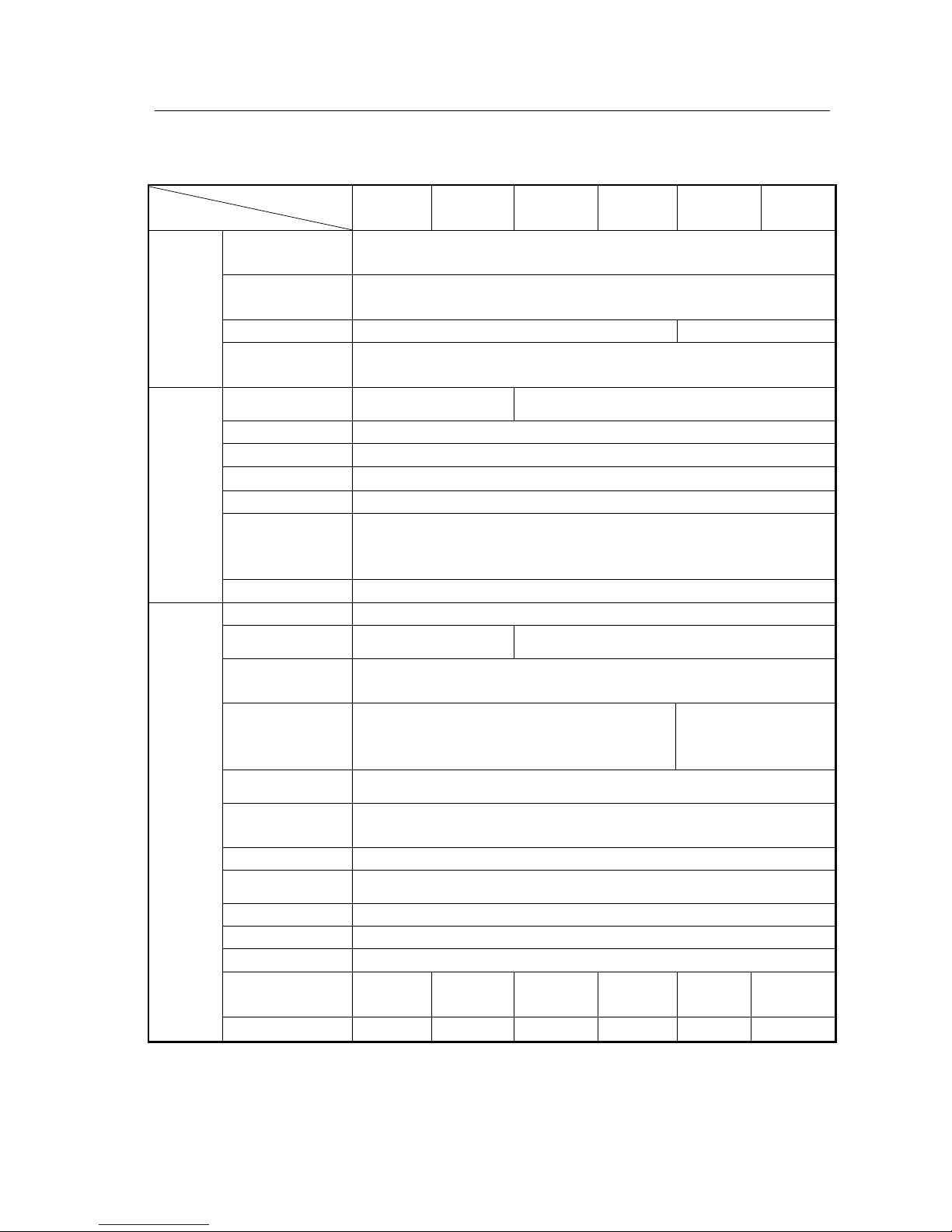
Table 2.2-1 KR Series (6-10KVA) Main Technical Specification
Model
Index
KR6000
KR6000L
KR1110S
KR/B1110S
KR1110
KR/B1110
KR3110S
KR/B3110S
KR3110
KR/B3110
Input Characteristic
Rating voltage (V)
120~140Vac half full load, 140~160Vac 75% full load,
160~276Vac 100% full load
Rating Frequency
(Hz)
50±10%
Phase
Single-phase three-line
Three-phase fiv-line
Battery voltage
(Vdc)
192
Output Characteristic
Capacity (VA/W)
6kVA/4.8kW
10kVA/8kW
Voltage (V)
220±2%
Frequency (Hz)
50±0.1%(Battery mode)
Waveform
Sine wave,,THD<3%
transfer time(ms)
0
Overload capacity
105%-130% rating load ,last 10min then turn into bypass
130%-150% rating load ,last 1min then turn into bypass
Above150% rating load ,last 1 sec then turn into bypass
Output Mode
Terminal
Other Characteristic
Back up Time
Configure optionally
Charge recovery time
<20 H(100AH a group)
<20 H(100AH a group)
Communication
interface
RS232/USB interface supports Upslion 2000 software and
SNMP protocol (optional)
Alarm
AC fail, low battery, Overload, Over temperature. UPS
fault, Incorrect input connection of phase-sequence
AC fail, low battery,
Overload, Over
temperature. UPS fault,
EPO function
when the EPO signal is off, output is off
Maintenance bypass
(optional)
with manual maintenance bypass, convenience for uninterruptible maintenance
Panel display
LED displays operation status and LCD displays parameter
Audio-noise (dBA)
<65
Protection function
Low battery, over voltage, overload, short-circuit and over temperature.
Working temperature
0~40℃
Relative humidity
0~95%,No condensation
Size (mm)
(W × D × H)
255×565×
700
255×565×
500
255×565×
700
255×565×
500
255×565×
700
255×565×
500
Weight (Kg)
69
23
70
24
71
27
Specifications are subject to change without prior notice.
Page 12
KR series(6-10kVA)user’s manual
- 9 -
3. Basic Principles and Structure
Summary
This chapter mainly introduces the principle and overall structure of KR Series (6&10kVA) UPS, including
the display meanings of panel indicator lights and definitions of external interface.
3.1 Working Principle of Single unit
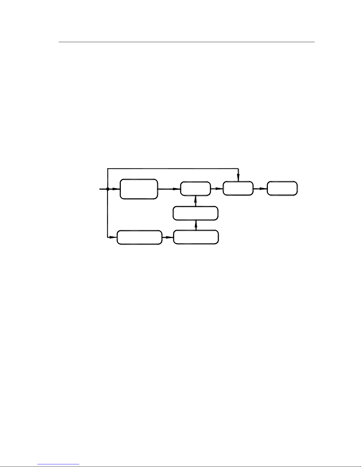
3.1.1Working Principle Diagram
CHARGE
PFC AC/DC
SW
BATTERY
DC/DC
DC/AC
LOAD
AC INPUT
Fig.3.1-1 KR Series Working Principle Diagram
3.1.2 Working Principle
UPS KR(6-10)KVA is made up of PFC, AC/DC (Commercial power rectification and boost
circuit), DC/DC (battery voltage-boost circuit), DC/AC inverter, switch, charger and battery
group etc.
When commercial power is normal, through PFC, it can be boosted to stabilized DC supplied
for DC/AC inverter to output steady 220VAC and finish battery charge at the same time. When
commercial power is abnormal, through DC/DC, the battery voltage will be increased to
stabilized DC supplied for DC/AC inverter. Because of PFC and power-down fast-test
technique adopted, even when the commercial power voltage lows to limit 120V, the battery
group can still have no output current to assure battery longevity and be kept in energy-storage
status and if commercial abnormal battery voltage-boost will start up at once to assure steady
DC/AC output.
As shown in the Figure 3.1-1, the DC/AC inverter adopts half-bridge structure, DC/DC module
uses boost-circuit, PFC is active power-factor correction circuit and CHARGER is a kind of
complete isolation charger.
Page 13

KR series(6-10kVA)user’s manual
- 10 -
3.1.3Working Procedure
When 220Vac normal, main DC circuit has DC voltage supplied for DC-AC AC-inverter which
outputs stable 220Vac and charges battery at the same time. Whenever commercial power was
low or broken down suddenly, the battery group would feed back electric power to DC circuit
through DC/DC voltage-boost module. There is no transfer time from mains supply to battery
supply. When batteries’ energy is used up, UPS would send out audio-light warning till battery
voltage drop to the discharge limitation point then UPS would stop inversion and emit lasting
sound. In addition, UPS has overload protection. When overload (125% full load) happens,
UPS would turn to bypass supply and return if load recovers normal. When more serious
overload (over 150% full load) appears, UPS would halt inversion and switch to bypass
supply-at the time the switch may have jumped. After fault of load eliminated, as long as turn
on the switch, UPS will restart to work again. Audio-light warnings will always go with UPS
when UPS abnormal. The warnings or protections are shown in detail in Table 3.1-1.
Table 3.1-1 The Functions of Abnormal Status and Warning Protections
UPS Status
Beep
Indicators On Panel
LCD Display
Protection
/Warning
Normal
No beep
INV. On, Line on,
Bypass off, Fault off,
Output on
“Output Voltage
220.0 V ”
No.
105% overload
Once every 1.5 sec
INV. On, Bypass off,
Fault off, Output on.
“Output 220.0V
OVERLOAD ”
Turn to bypass
supply in 10 min
125% overload
Long beep
Bypass on, INV. Off,
Fault on, Output on in 1
min
“Output 220.0V
OVERLOAD ”
Turn to bypass
supply in 10 min
150% overload
Long beep
INV. Off, Bypass on,
Fault on, Output on
“Output 220.0V
LOAD PROTECT”
Protected
Low-voltage point
Once every 0.5 sec
INV. On, Line off,
Bypass off, Fault off,
Output on
“Output 220.0V
BAT. LOW ”
Waning
Battery voltage below
protection point
Long beep
INV. Off, Line off,
Bypass on, Fault on,
Output off.
“Output 220.0V
BAT. PROTECT”
Protected
Input breaker cutoff or
input abnormal
Three beep with
100ms interval every
10 sec
INV. On, Line off,
Bypass off, Fault off,
Output on
“Output 220.0V
LINE FAIL”
Warning
Over temperature
Long beep
INV. Off, Line off,
Bypass on, Fault off,
Output on
“Output 220.0V
OVER TEMP”
Protected
Output over-voltage,
Output low-voltage
Long beep
INV. Off, Bypass on,
Fault on, Output on
“Output 220.0V
INVERTER FAIL”
Protected
Page 14
KR series(6-10kVA)user’s manual
- 11 -
Short-circuit
Long beep
INV. Off, Bypass on,
Fault on, Output on
“Output 220.0V
OUTPUT SHORT”
Protected
Note: If commercial power recovers after low-voltage protection to battery, the product will restart and charge batteries.
3.2 Parallel System Principle
3.2.1Working Principle
Parallel flow equalization of AC input is mainly through rapid adjustment of paralleled single’s
output waveform, amplitude and phase, then make them strictly the same, to achieve current
sharing purposes. Any difference of the voltage amplitude or phase may have a great
circulation; seriously, it may cause overload or inverter damage. As the high-power UPS itself
may have large interference, therefore, parallel systems must have strong anti-interference
features, thus ensure the system reliability service.
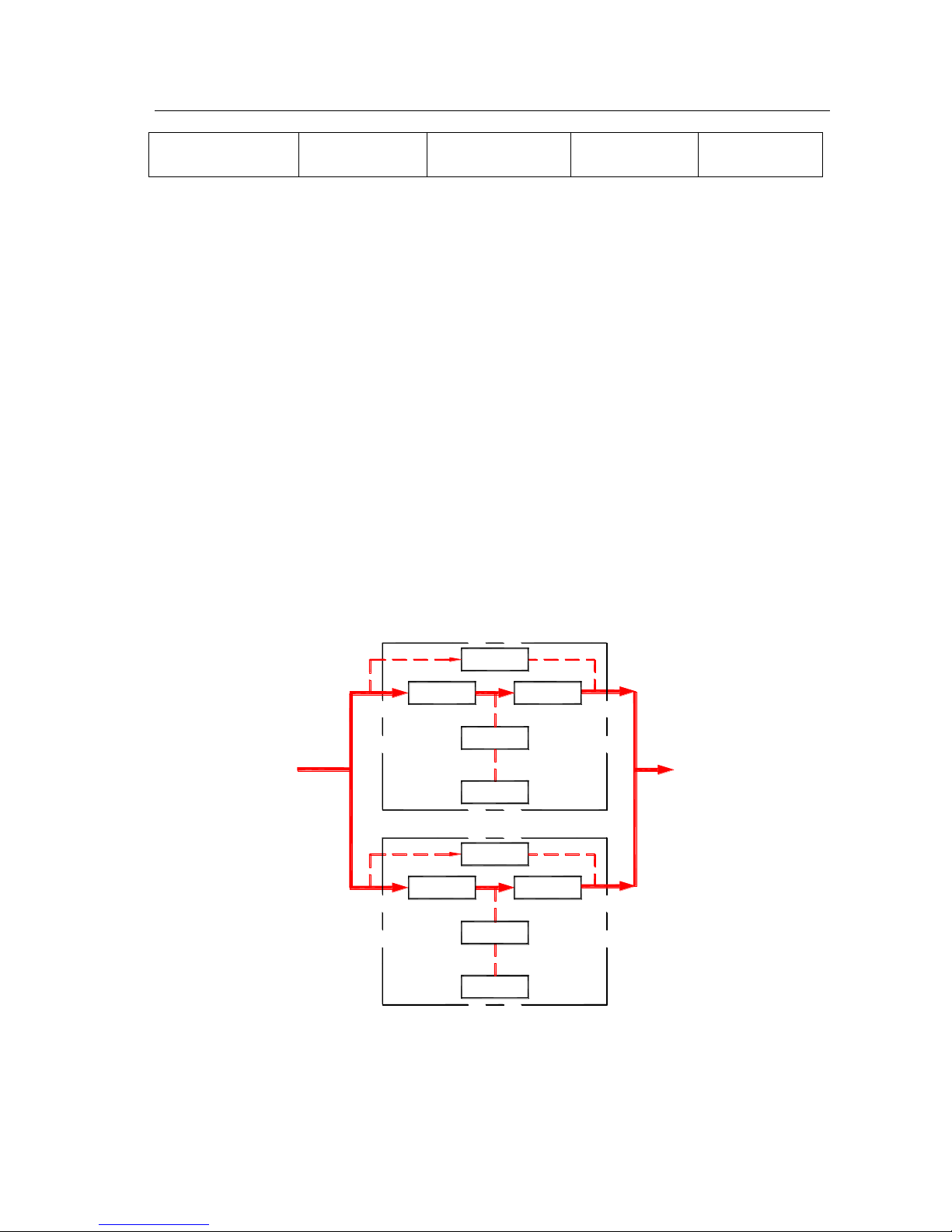
3.2.2Working Mode
Diagram of Parallel system is shown as Fig.3.2-1.
PFC
DC/DC
PFC
DC/DC
Bypass Switch
Inverter
Load
Battery
Main(UPS2)
AC Input
Bypass Switch
Inverter
Battery
Main(UPS1)
Fig.3.2-1 Diagram of Parallel System
Page 15
KR series(6-10kVA)user’s manual
- 12 -
Parallel units all have independent bypass, two UPS can directly parallel without parallel control cabinet or
extra public bypass input, so that they are easy to install and maintain.
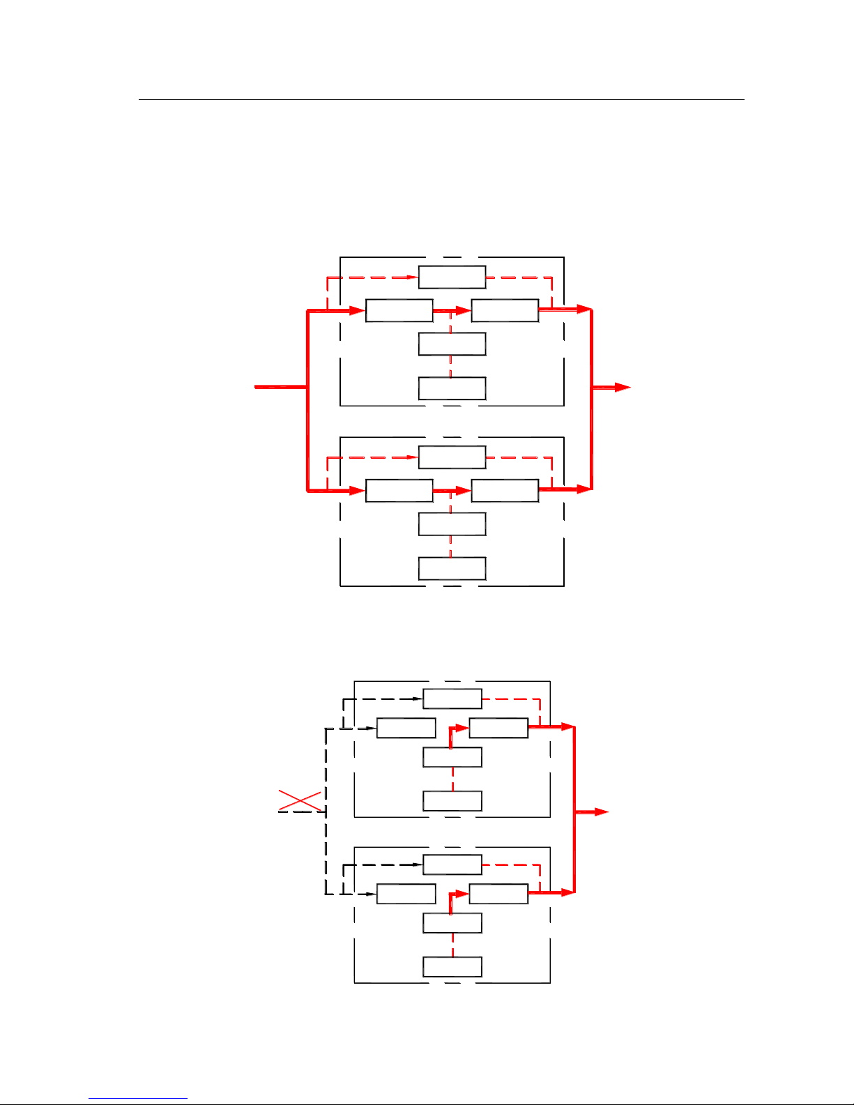
There are below four main working modes of parallel system:
1、Working mode of utility normal (solid line is Energy flow of UPS) as shown in Fig.3.2-2.
DC/DC
PFC
PFC
DC/DC
Bypass Switch
Inverter
Load
Battery
Main(UPS2)
AC Input
Bypass Switch
Inverter
Battery
Main(UPS1)
Fig 3.2-2 Working mode of utility normal
2、Working mode of utility abnormal (solid line is Energy flow of UPS) as shown in Fig.3.2-3.
PFC
DC/DC
DC/DC
PFC
Bypass Switch
Inverter
Battery
Load
Main(UPS2)
Bypass Switch
Inverter
Battery
Main(UPS1)
AC Input
Fig3.2-3 Working mode of utility abnormal
Page 16
KR series(6-10kVA)user’s manual
- 13 -
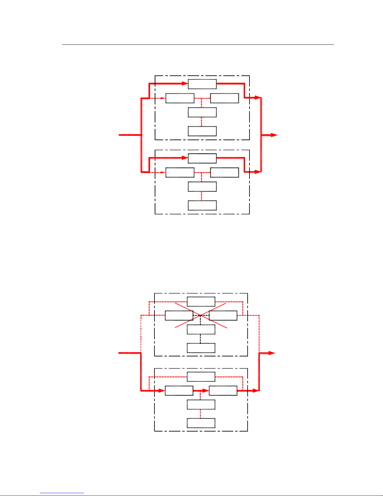
3、Working mode of overload (solid line is Energy flow of UPS) as shown in Fig.3.2-4.
PFC
DC/DC
DC/DC
PFC
Bypass Switch
Inverter
Load
Battery
Main(UPS2)
AC Input
Bypass Switch
Inverter
Battery
Main(UPS1)
Fig.3.2-4 Working mode of overload
4. Working mode of one machine abnormal (solid line is Energy flow of UPS) as shown in
Fig.3.2-5. Abnormal machine doesn’t have output, so supply power to load only by normal
machine.
PFC
DC/ DC
DC/ DC
PFC Inverter
Battery
Load
Main(UPS2)
Bypass Switch
Bypass Switch
Inverter
Battery
Main(UPS1)
AC Input
Fig.3.2-5 Working mode of single machine abnormal
Page 17
KR series(6-10kVA)user’s manual
- 14 -
3.3 Machine Structure
3.3.1Display structure
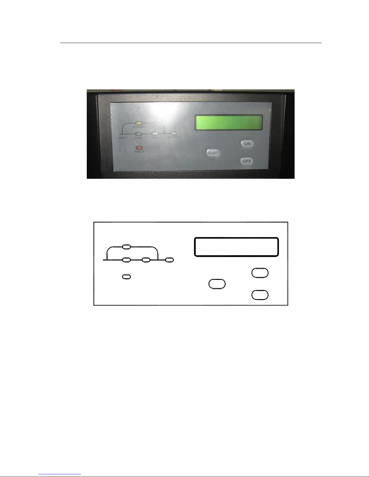
3.3-1 KR Series 6&10KVA display panel
3.3.2 Display interface
INV.LINE
BYPASS
OUTPUT
SELECT
ON
OFF
FAULT
INPUT
①
②
③
④
⑤
⑥
⑦
⑧
⑨
3.3-2 KR 6&10KVA display interface
LCD display illustration:
① “LINE” : When commercial power is normal, light on; abnormal, light off; when live wire
and neutral wire reverse, light fliter (three phase in single phase out type is without this
function ).
② “INV.” : Inverter normal, light on; abnormal, light off
③ “OUTPUT” : UPS has output, light on; no output off.
④ “BYPASS” :UPS in status of bypass supply, light on; in status of inversion, off.
⑤ “FAULT” :UPS fault, light on; normal, off.
⑥ LCD Display panel.
Page 18
KR series(6-10kVA)user’s manual
- 15 -
⑦ “Select”: When UPS is normal, LCD displays normal output voltage. If the button pressed,
the background light on and the LCD display will show input voltage, input frequency, output
power, UPS status etc.
⑧“ON” :When UPS is shutdown, press the button for 1 sec, UPS starts up. When UPS is
running, press the button for 1 sec, UPS will enter battery test model. When battery voltage
reaches the low-voltage point or test time last 10 sec, UPS will stop the function. When battery
is working of INV., press the button for 2 sec, the buzzer will stop the discontiguous beep, but
the warning is not eliminated of battery low-voltage etc.
⑨“OFF” :When UPS is running, press the button for 1 sec, UPS will shut down.
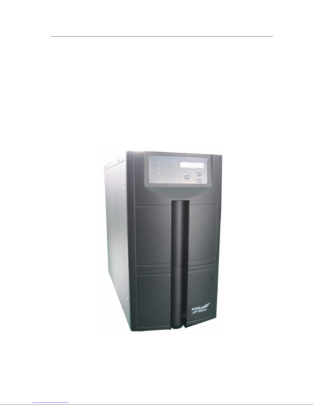
3.3.3 KR6000L, KR(/B)1110, KR(/B)3110 appearance
3.3-3 KR 6000L, KR (B)1110, KR(/B)3110 appearance
Page 19
KR series(6-10kVA)user’s manual
- 16 -
DISPLAY
AIR
INLET
INV.LINE
BYPASS
OUTPUT
SELECT
ON
OFF
FAULT
INPUT
⑩
④②①③
⑤
⑥
⑦
⑧
⑨
OFF
BATTERY
ON
POWERBYPASS
EPO USB RS232
RS232
USB
EPO
SNMP
(optional)
POWER Breaker
BATTERY Breaker
BYPASS Breaker
FANS
LINE BAR
COVER
MANUAL
MAINTENANCE
BYPASS
(optional)
OFF
BATTERY
ON
POWERBYPASS
EPO USB RS232
RS232
USB
EPO
FANS
LINE BAR
COVER
MANUAL
MAINTENANCE
BYPASS
(optional)
SNMP
(optional)
POWER Breaker
BATTERY Breaker
BYPASS Breaker
PALL.
PALL.
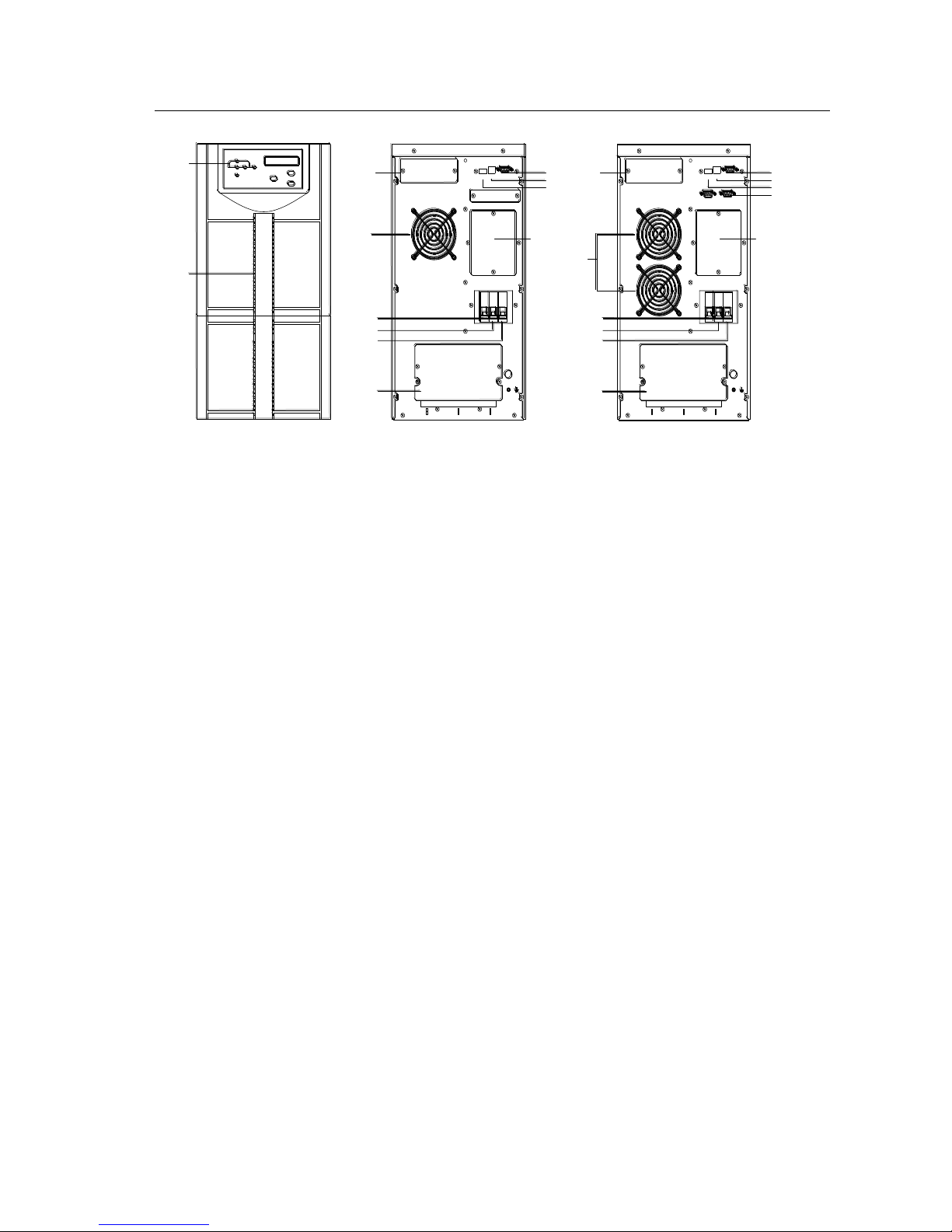
Front panel KR6000L rear panel KR(/B)1110, KR(/B)3110 rear panel
3.3-4 KR6000L, KR(/B)1110, KR(/B)3110 Front Panel and Rear Panel
Page 20
KR series(6-10kVA)user’s manual
- 17 -
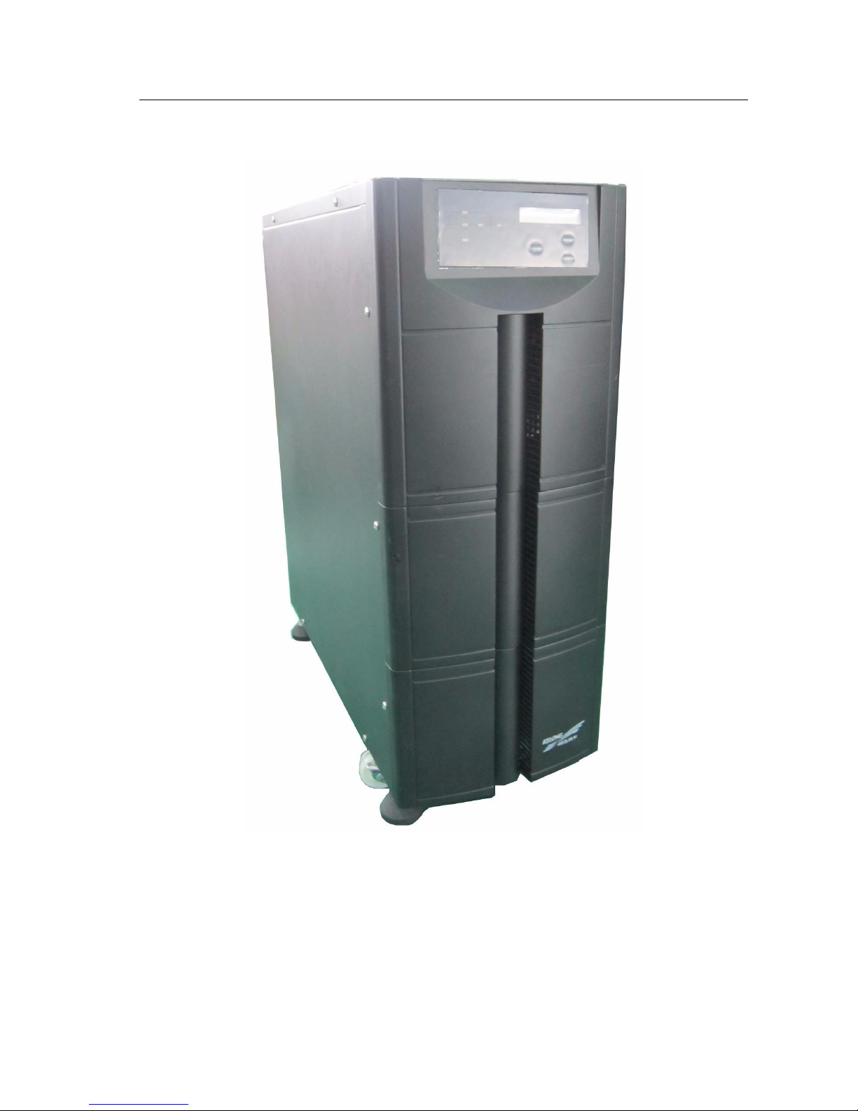
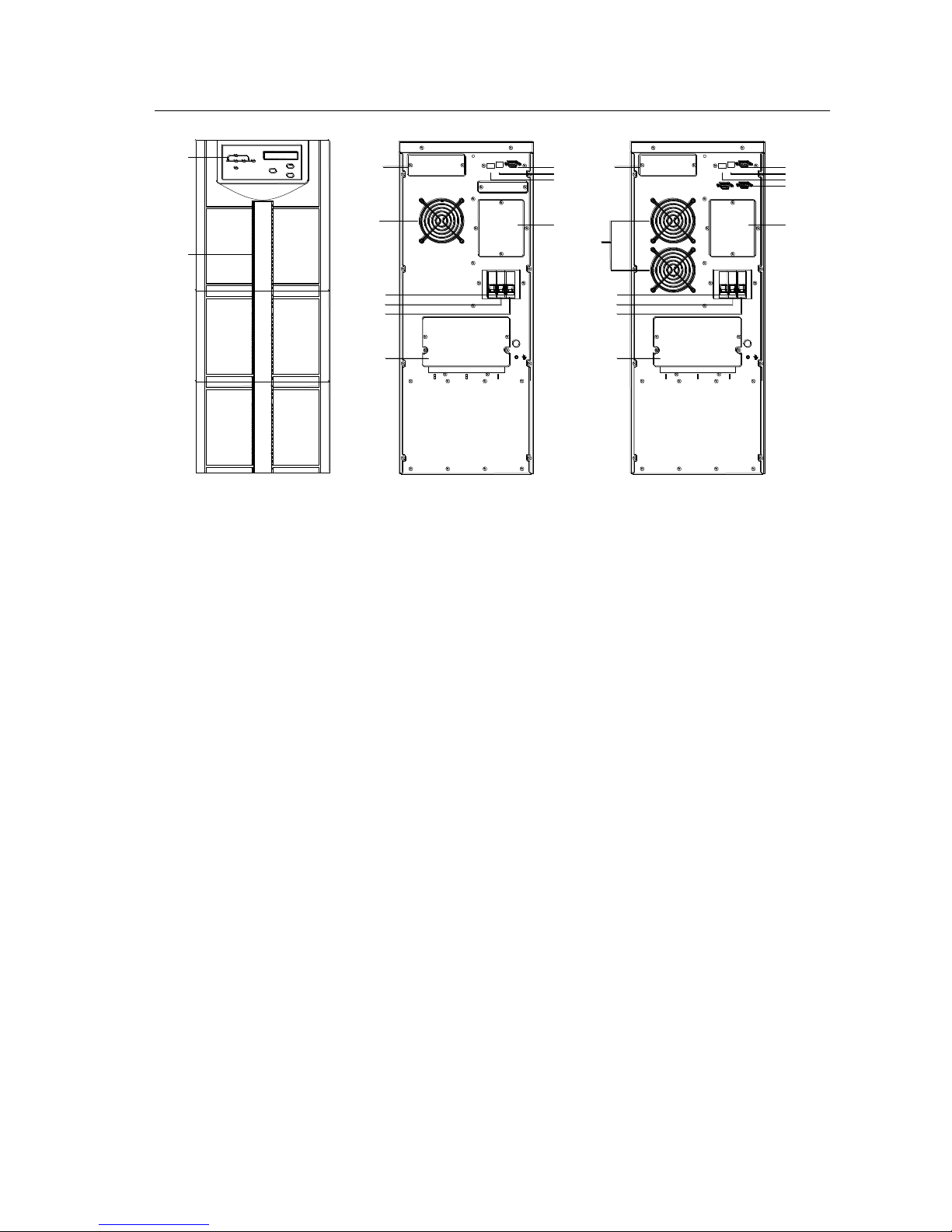
3.3.4 KR6000, KR(/B)1110S, KR(/B)3110S appearance
3.3-5 KR6000, KR(/B)1110S, KR(/B)3110S appearance
Page 21
KR series(6-10kVA)user’s manual
- 18 -
DISPLAY
AIR
INLET
LINE BAR
COVER
INV.LINE
BYPASS
OUTPUT
SELECT
ON
OFF
FAULT
INPUT
⑩
④②①③
⑤
⑥
⑦
⑧
⑨
OFF
BATTERYONPOWERBYPASS
EPO USB RS232
RS232
USB
EPO
MANUAL
MAINTENANCE
BYPASS
(optional)
FANS
LINE BAR
COVER
OFF
BATTERYONPOWERBYPASS
EPO USB RS232
RS232
USB
EPO
SNMP
(optional)
FANS
MANUAL
MAINTENANCE
BYPASS
(optional)
SNMP
(optional)
POWER Breaker
BATTERY Breaker
BYPASS Breaker
POWER Breaker
BATTERY Breaker
BYPASS Breaker
PALL.
PALL.
Front panel KR6000 rear panel KR(/B)1110S, KR(/B)3110S rear panel
3.3-6 KR6000, KR(/B)1110S, KR(/B)3110S Front Panel and Rear Panel
Page 22

KR series(6-10kVA)user’s manual
- 19 -
4. Installation
Summary
The chapter introduces notice, flow and installation steps
4.1 Installation Notice
1. Before installing UPS, check if the feeding circuit of grid is clear, including contacts of all
the connection points as well as sockets are OK, so as to avoid open circuit or short circuit.
2. As for the input which is one-phase-three-lines system, do check whether the grounding is
good and ensure the voltage between zero line and grounding line is less than 5V. If the input
grounding line of mains supply is null, the voltage could be 100V. If the users’ load has strict
requirements on the voltage between the zero line and the grounding line of the power supply,
make sure the grounding of the mains supply is good so as to avoid unnecessary loss.
3.When you are installing UPS, do not connect the zero line, live line and grounding line of
Input and output of the UPS reversely or wrongly so as to avoid short circuit .Meanwhile,
Please check whether the voltage of the mains supply is normal.
4.If battery group installed for long back up time, do strictly accord with connection method
and sequence prescribed by the installation manual to wire and the wiring must be tie tightly.
Short-circuit to the polarities of battery and touch any two wiring terminals simultaneously or
bare ends of connecting wire are absolutely forbidden. Otherwise, it would result in battery
damage or even person injury. When battery group connected to UPS, check if the voltage of
battery group coincides with that demanded by UPS.
5. UPS installation requirements
◆ Lie UPS on the flat ground (avoid sloping and scabrate ground)
◆ Do not place goods on the UPS nor do the person sitting.
◆ Avoid place at location such as sunlight, rainy and moist.
◆ Avoid place where etchant gas included in the air
Page 23
KR series(6-10kVA)user’s manual
- 20 -
◆ If UPS are placed at location under 0℃ too long, please turn on the UPS before temperature above 0℃ for more
than 2 Hours.
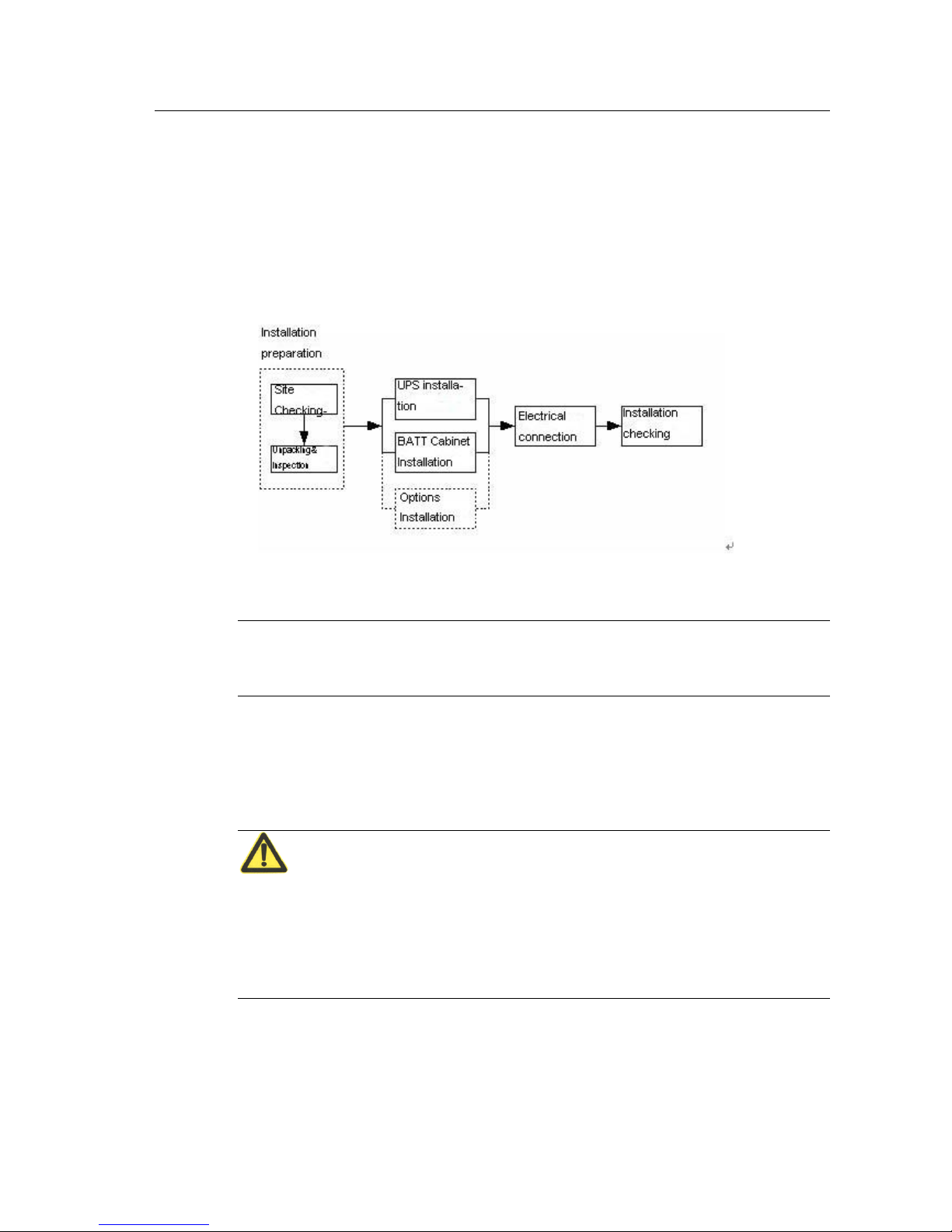
4.2 Installation process
Installation process for KR Series (6&10kVA),please see Fig.4.2-1
Fig.4.2-1 installation chart for UPS system
Note:
Tested and installed only by manufacturers or authorized engineers.
4.3 Installation preparation
4.3.1 Checking the installation site
Attention:
Before installing UPS, please ensure sites and environment meet basic conditions prescribed in
this chapter to ensure UPS running safely and normally. If sites not reach basic conditions,
please reconstruct accordingly. Only after site meet basic requirements that UPS can be
installed.
4.3.1.1 Environment Requirement
Ambient temperature
Relative humidity: 0%RH~95%RH, no condensation;
Cooling mode: air cooling;
Page 24
KR series(6-10kVA)user’s manual
- 21 -
Altitude: meet GB/T 7260.3-2003;
Verticality: no shock with orthogonal rake not exceeding 5;
Pollution rank: Class Ⅱ;
The UPS should be installed in the environment where exists enough ventilation, coolness, not
too high temperature and without dust. The recommended work temperature is 20~25℃ and the
humidity should be controlled around 50%.
Note: Not allowed to install at environment with dust of metal conduction.
4.3.1.2 Power supply requirements
1.Grounding preparation.
Grounding terminals are ready, and voltage between Zero line and ground line is less than 5 V.
2.AC input voltage and load capacity of incoming line of mains supply
Before installing UPS, please ensure the AC input voltage and load capacity of incoming line of mains
supply meet the requirements of devices, to take the decreased in current carrying capacity by aging of wire
into account.
3.Equip Breaker protection for AC input
Install breaker or power distribution boxes that match with the power of mainframe before the input cable of
mainframe to isolate mainframe and mains supply. Taking into account the impulse current of power on
moment, the breaker be selected must be 1.5~2 Times of Maximum current of Mainframe, and breaker
should not with leakage protection to avoid improper operation of breaker. Selection of breaker please see
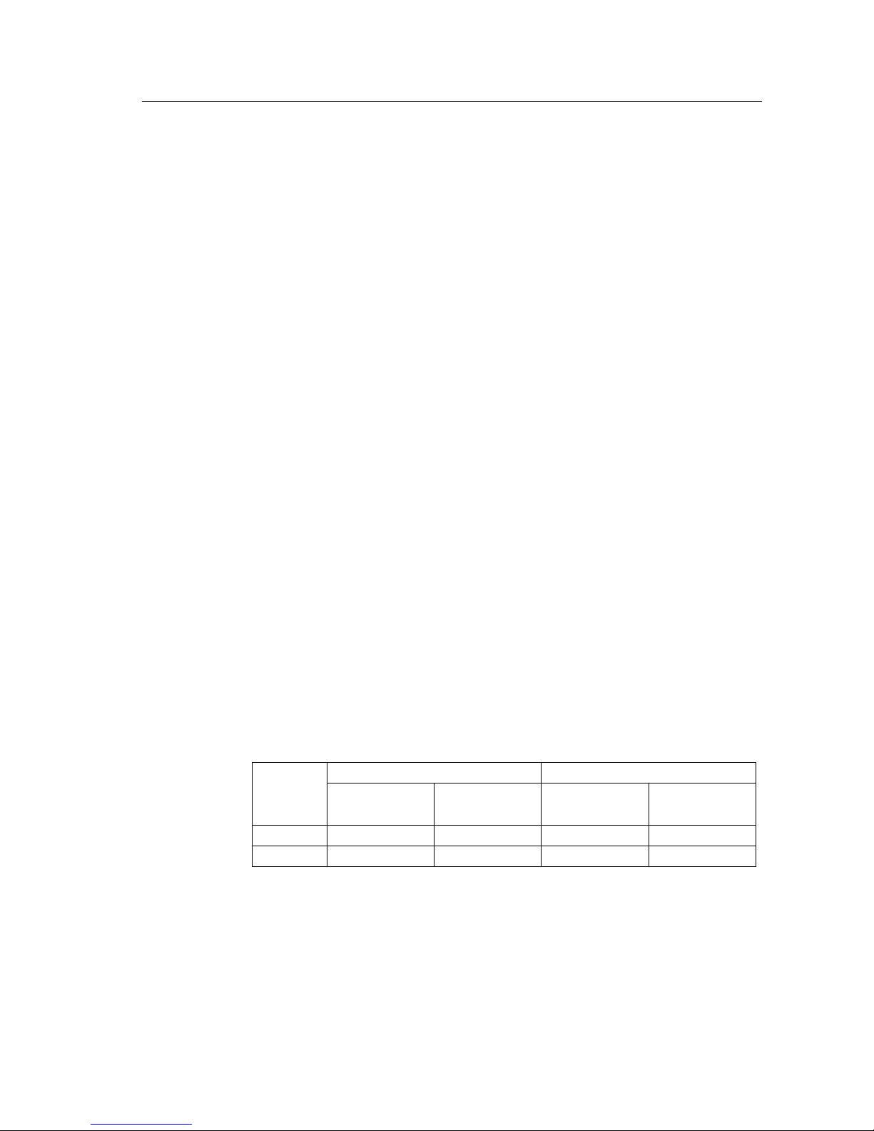
details at table 4.3 -1:
Table 4.3 -1 Recommended value of breaker
KR6kVA
KR10kVA
MAX Current(A)
Recommended
Breaker(A)
MAX Current(A)
Recommended
Breaker(A)
AC Input
37.5
100
57
100
DC input
45
100
38
100
4. Selection of Input and output cable
Selection of Conductor sectional for the input&output cables of UPS and battery cable, please refer to
corresponding recommended value listed on table 4.3-2.
Page 25

KR series(6-10kVA)user’s manual
- 22 -
Table 4.3-2 Recommended Conductor sectional of UPS (mm2)
KR6kVA
KR10kVA
AC INPUT(Live and
Zero line)
6
10
AC INPUT(G)
6
6
DC INPUT( Positive
and Negative )
10
10
AC OUTPUT(Live
and Zero line)
6
10
Cross-sectional area of cable mentioned above is only suitable for 5 meters cable. If length of
lead is longer than 20 meters, the Cross-sectional area of cable must be enlarged accordingly.
5.lightning protection
Incoming line of mains supply must be equipped with multilevel lightning protection system to ensure
devices running safely at frequent lightning area. For outdoor installation, the lightning protection level of
AC input must be promoted.
4.3.2 Unpacking and inspect the machine
4.3.2.2 Transportation
1. Arrange appropriate transportation and lifting according to the size of packages, such as
forklift.
2. If the volume of packages are too big, there need to select unpacking site. Generally, the
unpacking site must the closer the better.
3. During the convey process, do pay attention to the turning, up gradient and down ramp to
avoid crash.
4.3.2.3 Unpacking
1.When installing, transport UPS to installation site to remove outer packing.
2. After unpacking, please check whether the component of systems is correct and complete
comparing to packing list.
Kindly Reminder:
For the convenience of future transportation and packing, please keep the packing materials.
Attention: Should you find the components are not inconsistent with PO, please record on site,
and contact local branch of Kehua Group or agencies immediately.
Page 26

KR series(6-10kVA)user’s manual
- 23 -
3. After unpacking, check whether the devices are mechanical damage caused by
transportation.
Kindly Reminder:
If UPS are found serious damage on appearance, further inspection must be performed and
make record on site. Meanwhile, please contact our local branch or agencies immediately.
4.4 Machine Installation
4.4.1 Machine installation notes
1. Do not place in areas with corrosive gases. Ensure that the UPS be placed in
well-ventilated location, to facilitate heat dissipation.
2.Placed the UPS in a horizontal position, avoid placing in the rugged and sloping areas. Do
not place objects on top of the cabinet.
3. Before wiring, do place the breaker of mainframe on the OFF status. Be sure not to connect Ground line
and Zero line, Live line and Zero reversely mutually result in short circuit. Ensure good grounding and the
voltage between Zero line and Ground line must be less than 5 V. If the output of UPS through other adapter,
quality should be guaranteed to avoid short circuit or open circuit.
4.5 Check the main input
Before installation, make sure load capability of grid satisfies the new equipment requirement
and the power accords with the voltage and frequency on the nameplate, if current carrying
capability declined because of aging of cables. If any doubt, please negotiate the solution with
the local mains supply department.
4.6 UPS Installation
4.6.1 KR (6&10kVA) Series UPS installation
Remove the UPS from bracket to ground for installation. Following are installation examples
for KR6000.
Page 27
KR series(6-10kVA)user’s manual
- 24 -
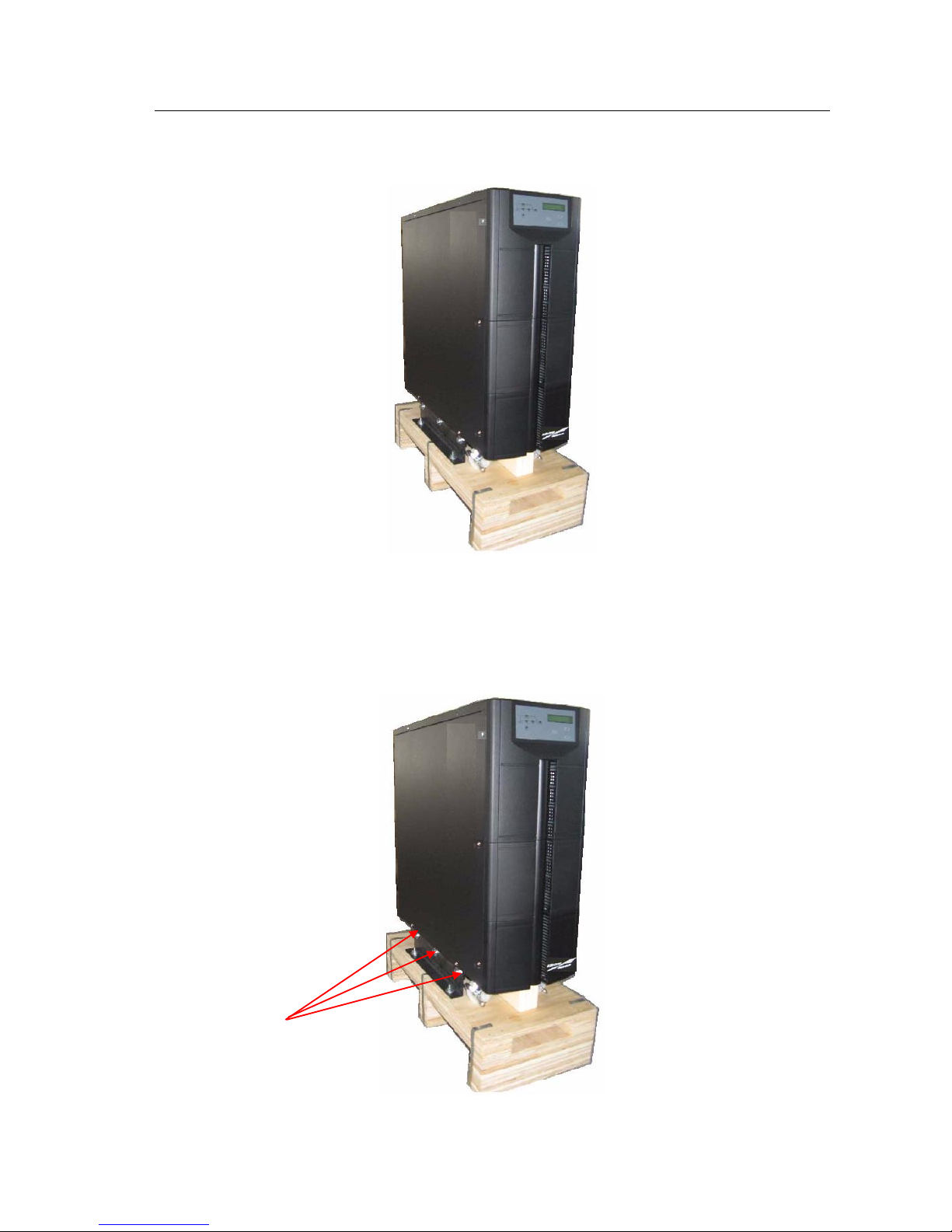
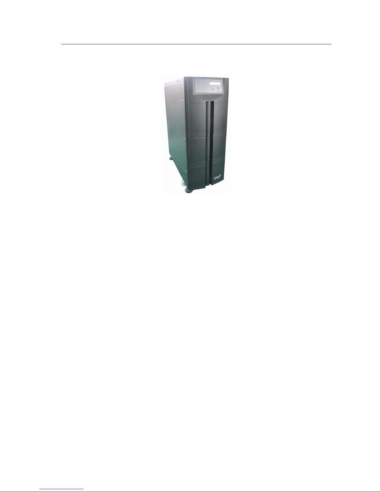
1. after unpacking KR6000, the external structure as below:
Fig 4.6 -1 Installation steps 1
2、Loosen and take down 6 pieces of Hexagon bolt M8×20 ( Two on both left and right side) between
Anchor frame and tail margin supporting plates.
Fig 4.6- 2 Installation steps 2
Hexagon bolt M8×20
Page 28
KR series(6-10kVA)user’s manual
- 25 -
3.Move UPS from Flat Pallets to ground, as following:
Fig 4.6 -3 Installation steps 3
4.7 Battery Cabinet Installation
For long back up time UPS, besides mainframe, also equip batteries and battery cabinet,
4.7.1Important Security Regulation
Do not unclench or detach battery, because it would result in injury to person skin and eye by
electrolyte inside them. To avoid electric shock or short-circuit, the following precautions
should be strictly complied with when replace batteries:
Do not wear watch, ring or other metal accouterment ;
Use tools with insulation handle;
No placement of tools or metal on the battery;
No fire is close to batteries and no smoking.
4.7.2 Installation Steps
1.To achieve safe operation and avoid unnecessary harm to the UPS, all the assembly
of external batteries should be executed by the professional technicians and follow the
manipulation sequence below:
1) Complete the wiring among the external battery groups but temporarily do not connect them to the input
end of external battery of UPS.
2) Connect the input power cable to UPS, assuring that the polarity and input voltage accord with the
specification.
Page 29

KR series(6-10kVA)user’s manual
- 26 -
2. Under the status that the AC input is normal and UPS has no load, turn on the main switch
of UPS to measure the DC voltage of external battery connection.
3. If the result, gained from step 2, called charge voltage is normal, then connect the external battery group
to UPS. At the moment, confirm that the connection polarity is correct.
4. After assembly and test finished, the UPS can be put into use.
4.8(Parallel)System installation
According to the installation methods described previously, connect battery and UPS
mainframe of parallel system respectively and independently; Connect AC output of each
parallel system to output power distribution box of parallel system.
Attention: Connection and phase sequence of AC input of each unit of parallel system must be
the same, ensure bypass power supply of parallel system in-phase.
Connect parallel ports of each unit of parallel system using shield communication cable
equipped. And fasten relevant screw of RS232.
4.9 Electrical connection
4.9.1 Mode of Single Unit Connection
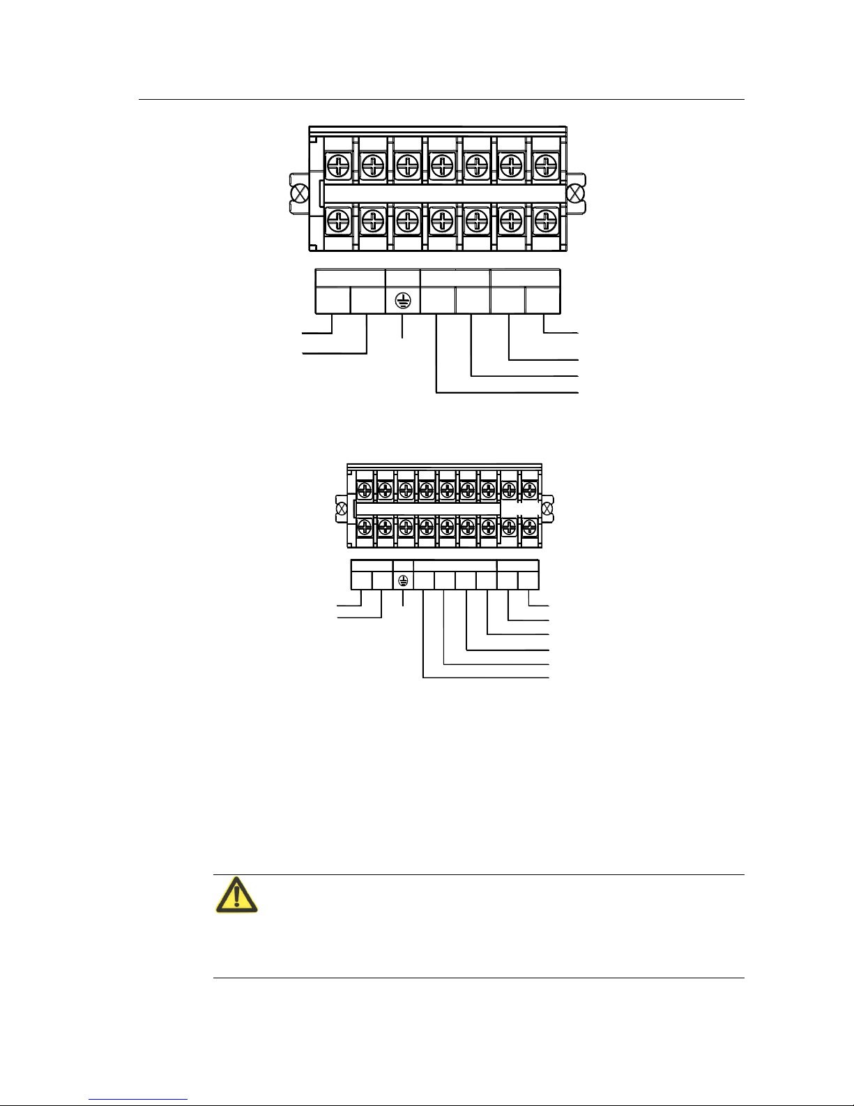
Connect power cord provided by manufacturers to relevant terminals and ensure reliability of
connection.
Attention1:
When wiring, make sure that the wires and terminals of input and output should be contacted
reliably, no disqualified contact and reversed wiring.
Attention 2:
For single unit application, there do not need additional wiring for bypass live line and Zero
line.
Page 30
KR series(6-10kVA)user’s manual
- 27 -
INPUT
OUTPUT
L
N N
L
PE
BATTERY
+
-
Grounding
AC Input "L"
AC Input "N"
192VDC
AC Output "L"
AC Output "N"
DC input("-")
DC input("+")
Fig 4.9-1 KR6000(L)、 KR(/B)1110(S) Connection methods of line bar
PE
U
NN
L
OUTPUT
INPUT
BATTERY
+
-
V W
Grounding
-
+
(240VDC)
AC Input "V"
AC Input "W"
AC Input "U"
AC Input "N"
AC Output "L"
AC Output "N"
Fig. 4.9-1 KR(/B)3110(S)Connection methods of line Bar
4.9.2 Wire Connection of Parallel system
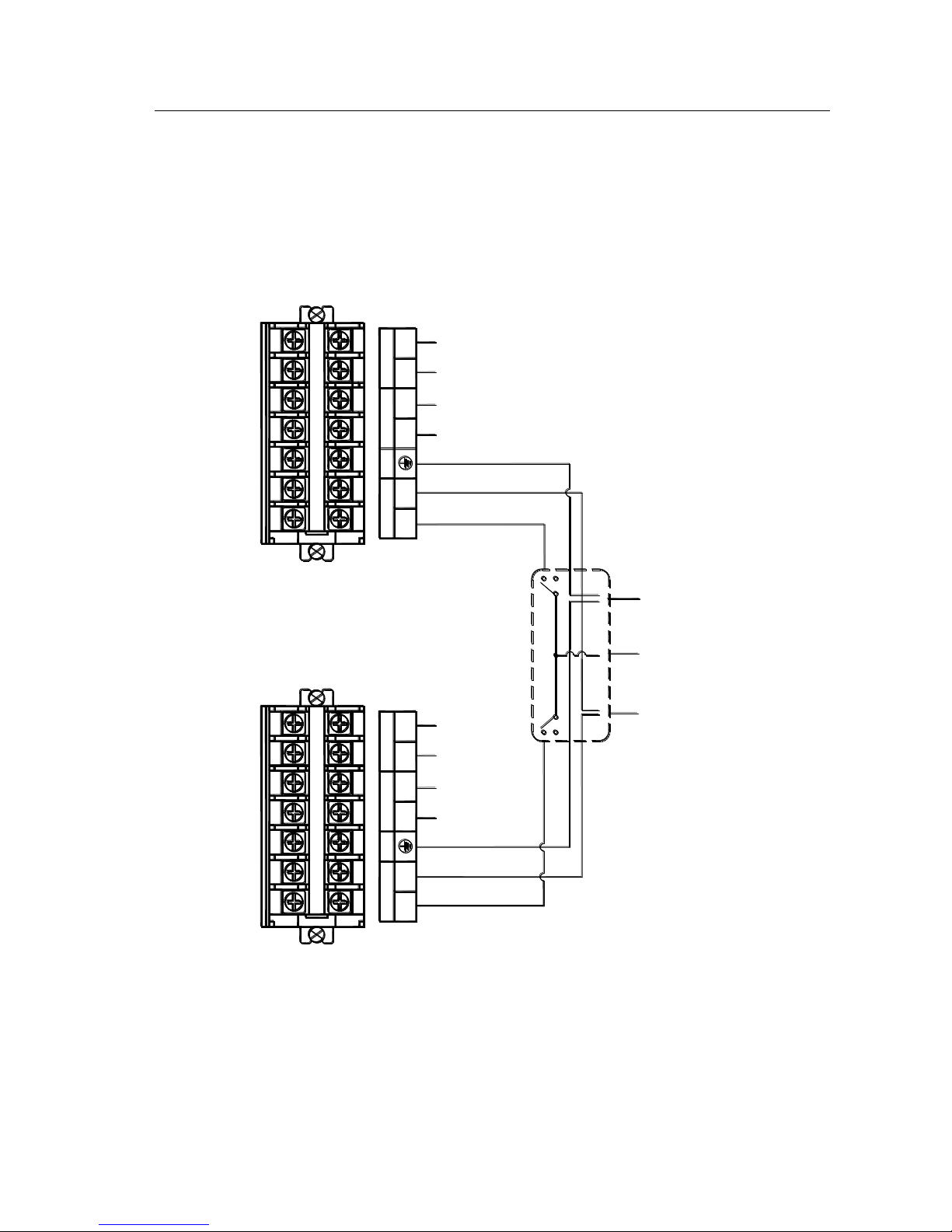
1. As per the installation process described above, install each battery and host UPS separately.
Connect the AC output of parallel cells to the output jack box of parallel system. (Details as
below , wire connecting method charts for each model).
CAUTION:
The AC input connection and phases sequences for each cell of parallel system should be
strictly consistent, ensuring a same phase for bypass power of parallel system.
Page 31
KR series(6-10kVA)user’s manual
- 28 -
2. Connect all the system cells’ parallel connecters with Shielded communication cables, then
lock RS232 Ports’ screws.
3. Parallel Connection for KR/B 1110(S) is demonstrated as in below figure 4.9-3.
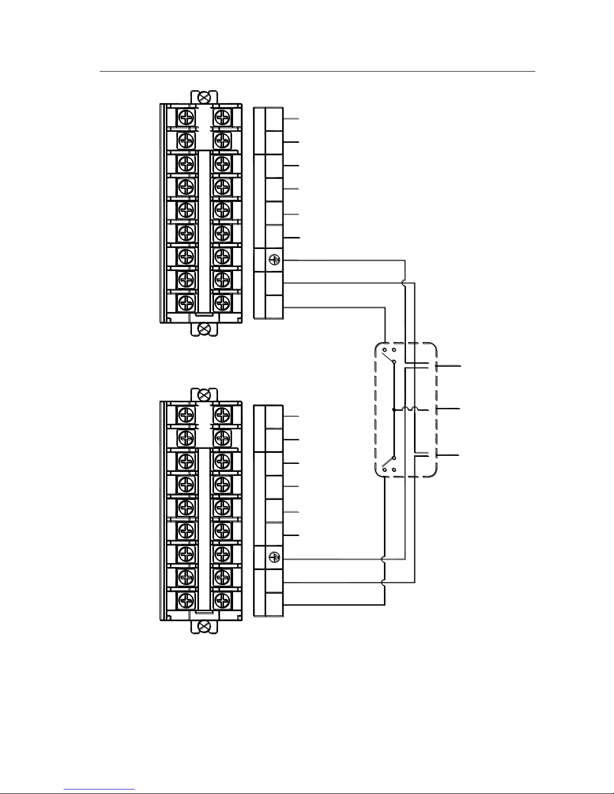
4. Parallel Connection for KR/B 3110(S) is demonstrated as in below figure 4.9-4.
-
+
BATTERY
PE
L
NN
L
OUTPUT
INPUT INPUT
OUTPUT
L
N N
L
PE
BATTERY
+
-
N L
GND
UPS1(L)
UPS2(L)
AC Input "N"
AC Input "L"
BATTERY-
BATTERY+
BATTERY-
BATTERY+
AC Input "L"
AC Input "N"
Power Distribution Box
GND
AC OUTPUT "L"
AC OUTPUT "N"
Fig 4.9-2 Parallel connection procedures for KR/B1110(S)
Page 32
KR series(6-10kVA)user’s manual
- 29 -
UPS2(L)
UPS1(L)
GND
LN
PE
U
NN
L
OUTPUT
INPUT
BATTERY
+
-
V W WV
-
+
BATTERY
INPUT
OUTPUT
L
N N
U
PE
Power Distribution Box
AC OUTPUT "N"
AC OUTPUT "L"
BATTERY-
BATTERY+
AC Input "W"
AC Input "V"
AC Input "U"
AC Input "N"
AC Input "N"
AC Input "U"
AC Input "V"
AC Input "W"
BATTERY+
BATTERY-
GND
Fig 4.9-4 Parallel connection procedures for KR/B3110(S)
Page 33
KR series(6-10kVA)user’s manual
- 30 -
4.10 System inspection and testing
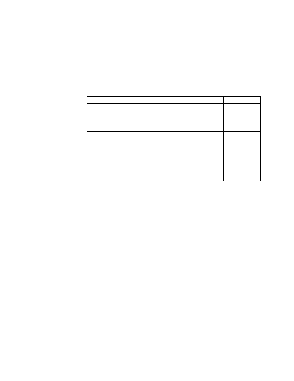
4.10.1 Check electrical connections
After electric connection, it’s required to check below items for electric connection results
following below instructions in below list.
Table 4.10-1 electric connection results examination
sequence
Examination Items
Results
1
Check if the color of AC input cable is correct
yes□ No□
2
Confirm if the wiring in the cabinet are not loose
yes□ No□
3
Check if the input switching unit’s safety precaution marks are
complete
yes□ No□
4
Check if the cable connect bars are firm
yes□ No□
5
Check if the polarity and sequence of battery cables are correct.
yes□ No□
6
Check if the cable marks are correct
yes□ No□
7
Check if the wiring is trim and the cable colligation comply with
technics criterion
yes□ No□
8
Check the device installation and wiring is propitious to future
modification, capacity expand and maintenance
yes□ No□
4.10.2 UPS testing
Test UPS: disconnect bypass switch or main source input switch, and then simulating main source failure is
allowed. Upon main source failure, main source “LINE” LED light black out and the buzzer will alarm 3
times every 10 seconds.
4.10.3 Connect with the load
Only after UPS starts and is stably working, then open the load device; first start high-power
devices, then start small power equipment. Some devices has large current upon starting which
may cause overload protection (or bypass operation). It is better to start such equipment before
the other devices.
Page 34

KR series(6-10kVA)user’s manual
- 31 -
5. Using and Operation
Summary
Operation steps and methods are introduced in this chapter,
including preparation before electrifying, UPS start steps when
main source is normal, as well as UPS start steps and indicator
light meaning when main source fail.
5.1 Notes of using UPS
1. Before the UPS startup, check if the load is proper, which should not exceed the rated power,
to avoid UPS overload protection or power supply from bypass all the time.
2. Do not use the switch on the UPS panel as the power switch of the load equipments. Should
strictly follow below sequence to turn on or off UPS: when startup, firstly turn on the switch on
the UPS panel then turn on the equipments’. While shutdown, firstly turn off the switches on
the load equipments then the UPS. In this way, frequent startup can be avoided.
3. Till the UPS startup into steady work status, turn on the load equipments with sequence of
high-power ones first and low power ones later because the startup current of some equipments
are large enough to result in over-load protection (or bypass protection). So it is advisable to
start such equipments before the others.
4.When the UPS connected to the generator necessary as the mains supply cut off,
firstly start the generator. Until the generator is on steady work status, turn on UPS,
otherwise, the UPS or the load equipments may be damaged. And reversely,
disconnect the UPS firstly and then the generator before the generator turned off.
5.2 UPS single unit operation process
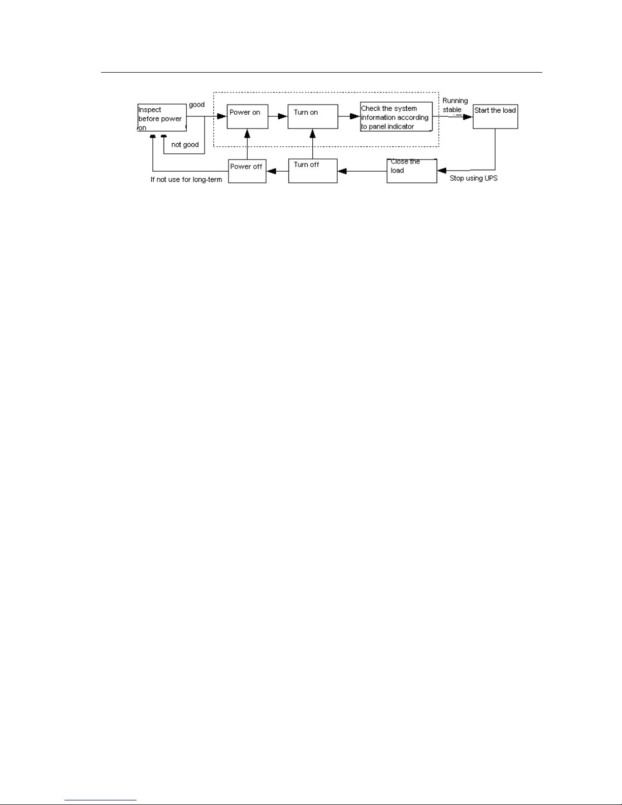
The operation steps are demonstrated as below figure 5.2-1. For the first time starting the UPS,
it’s required to check before power on. As introduced in 5.3.1 section, when confirm all is in
good condition, the UPS can be turned on. If UPS will not be used for long time, it needs to be
checked before power on.
Page 35
KR series(6-10kVA)user’s manual
- 32 -
Fig. 5-2.1 single unit operation Steps for KR series(6&10Kva)
5.3 Operation instruction
5.3.1 Inspection before power on
Before electrifying for the UPS, please check following below requirements. Only when
confirm all is in good condition, the UPS can be started.
1. Connect rated power to the input terminal bar.
2. Check the load equipments
(1) Confirm the load is non-inductive load. UPS is not recommended to connect with the
inductive load, such as motors, fans, air conditioners etc. Such loads usually use the grid power
directly.
(2) Make sure that the load is turned off. Meanwhile, the load capacity shall not exceed the
UPS rated output capacity, otherwise, it will cause the system overload protection. Calculation
of load capacity as follow:
KR series UPS load capacity are designed as per 80% (nominal rated power) of the
resistant load. Generally UPS with computer load can withstand the maximum load number
n estimated as following:
1ni
pi p
P is UPS output capacity(VA), Pi is the No. i load capacity(VA).
3. Confirm the UPS has no short circuit between the input live line and neutral line and
between the live line and the ground line. Also confirm no short circuit between the output
lines.
4. Check if the air breaker on UPS is on “OFF”.
Page 36

KR series(6-10kVA)user’s manual
- 33 -
5. Make sure the computer and other devices are power off.
5.3.2 UPS Startup Steps
Electrifying: Turn the power switch “ON” on the real panel as per below sequence.
POWER→BATTERY
Start Up: press “On” key on the panel and startup inverter
Before UPS work stably, the automatic bypass will supply power to the load. At this time, all
the indicators are light except failure indicating light. A while later, bypass light is off, UPS
turn to inverter status and UPS has started and enter working with no loads.
5.3.3 Start the load
Observe the indicator on the pane, referring to below chart 3.3-2 to judge the working status of
UPS. When it indicates the UPS is in inverter working mode or battery working mode, it can
supply power to the load.
After the UPS has running about 10 minutes without load, start the load. according the
sequence "high-power equipment → low power equipment" .
Caution:
1. UPS is not allowed to connect with the inductive load, such as air conditioners, fans, starters,
electric drills, motors and daylight lamps etc.
2. Some devices has large starting current which may cause overload protection (or bypass
operation), it is better to start such equipment before the other devices.
5.3.4 Shutdown UPS
1. Turn off the load, let UPS working with no loads for 10 minutes to vent the inner
heat.
2. Turn off UPS: gently press “OFF” key on the panel to shut up UPS.
3. Disconnect power: turn the switch to be “OFF” on the rear panel following below
sequence. BATTERY→POWER
Page 37

KR series(6-10kVA)user’s manual
- 34 -
5.4. Operation of Parallel system
5.4.1 Parallel System start up
Please keep load off before Parallel System starting up, and make sure all the
breakers are off.
Startup steps as following:
1. After confirming correct installation, start parallel units in turns as per UPS start
steps.
2. When each unit has input from inverter mode, test inverting voltages of each parallel unit- the
difference between Max. and Min voltage should not exceed 5V. At this time, close the breakers of
each parallel unit’s switching box and the circumfluence current should less than 3A.
If the voltage difference is bigger than 5V, check whether the voltage of each UPS unit is 220V; If
the voltage difference is bigger than 10V, report for maintenance. In addition, too big
circumfluence current will lead to inverter damage. If the circumfluence current is bigger than 3A,
report for maintenance.
3. Then close the output switching box’s main air breaker, each output branch air
breaker, then start the loads in turn.
5.4.2 Parallel System Shut down
System should not be turned On-Off frequently when it works normally.
1. Shut down all the output loads of the Parallel System firstly.
2. Shut down each UPS unit following the shutdown sequence by pressing the Off
key on panel in turn.
3. Turn off the output breaker on each UPS unit (It’s allowed to not shut down in
daily usage.)
5.4.3 Online shutdown Parallel System
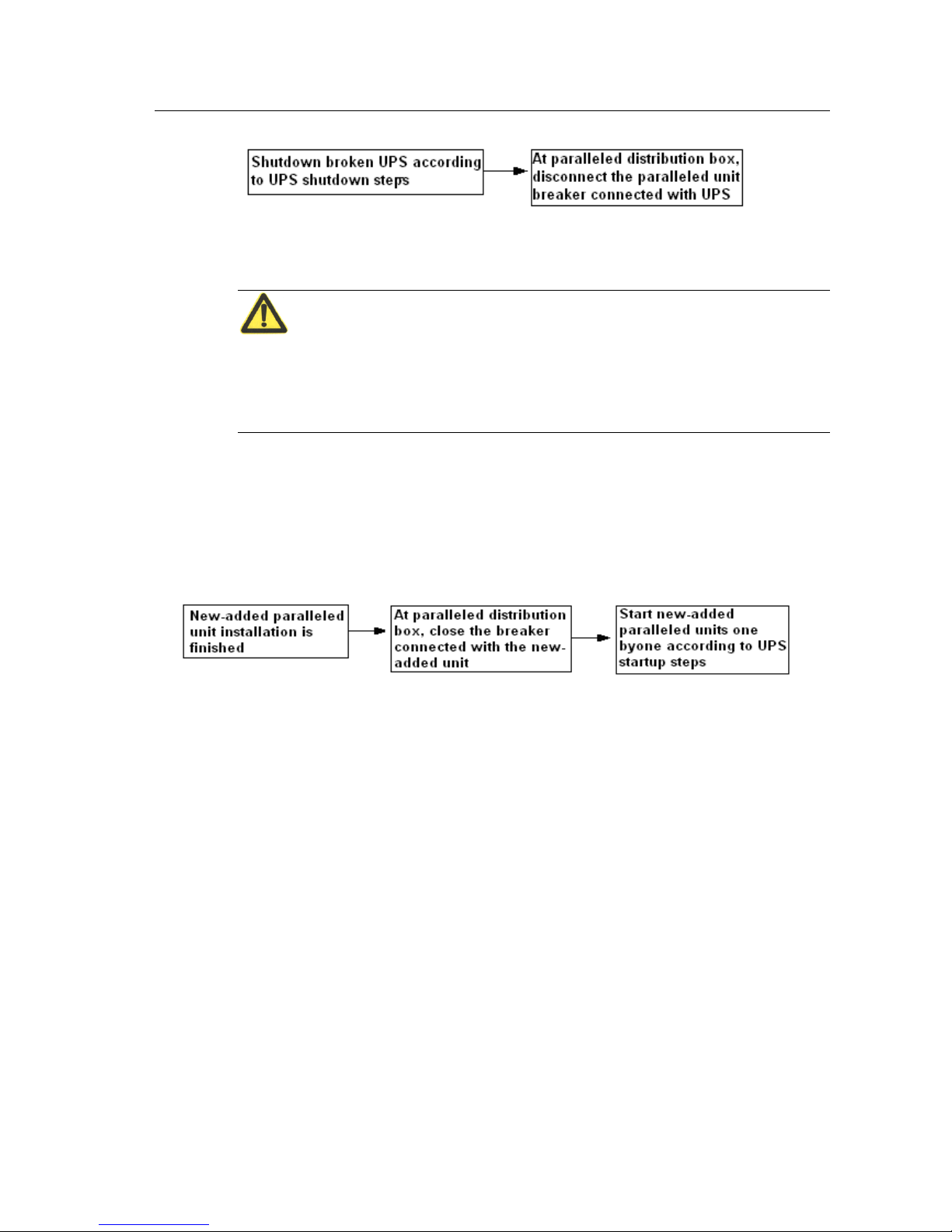
When a parallel unit fails, this parallel unit will quit the parallel system
automatically with voice and light alarm. Now, just operate the process according
to chart 5.4-1 to make the failed unit completely quit from parallel system, and
realize online hot maintenance or replacement.
Page 38
KR series(6-10kVA)user’s manual
- 35 -
Picture 5.4-1 online drop out Parallel Unit
Caution:
When the parallel system is working normally, it is better not to quit its output from
parallel system without shutting down parallel unit, otherwise the power system
will appear abnormal.
5.4.4 Online start-up Parallel System
When online launching one or more parallel unit is needed, just follow the
operation steps on Fig.5.4-2 After the new unit is operating stably, it will enter
parallel system automatically and achieve current sharing operation.
Fig.5.4-2 online Launch Parallel System
5.4.5 Redundancy and Expansion of Parallel System
1. Redundant Function
When using N+1 parallel redundant backup design, total output load should not be
large than N times of single machine rated output. When 1 single machine fails,
this single machine could launch and quit freely without affecting the operation of
parallel system, so it could improve the reliability of power system. When the
output exceeds above load, the overloaded single machine (exceed N/ (N+1) times
of single machine rated output) will alarm. For example, for double machines
backup power system, when the load of single machine exceeds 50%, it will alarm
the overloading.
Page 39

KR series(6-10kVA)user’s manual
- 36 -
2. Expansion Function
Theoretically, UPS parallel has no quantity limitation. However if the quantity is
over many, the reliability of the whole parallel system will decrease on the contrary,
and can not reach the aim of improving reliability. Therefore, we don’t suggest
using parallel mode to extend gross output power. In the application of UPS
parallel system, double machines parallel is frequently used.
Page 40

KR series(6-10kVA)user’s manual
- 37 -
6. Maintenance and Fault Diagnosis
Summary
This chapter describes the maintenance guide, battery daily maintenance,
battery replacement precautions and fault diagnosis.
6.1 Maintenance Guide
Proper maintenance is the key to enable that the device can run in the best and with
a longer service life
6.1.1 Safety Precaution
Pay attention to the following safety operation regulations:
1. Do remember there always exist hazardous voltage inside UPS even when UPS
do not run. Please make sure that the power is cut off and safe before maintenance
2. When UPS operation, no golden or sliver accouterments like ring, watch wore.
3. Don’t assume the safe operation procedure as a matter of course. If any doubt,
consult with persons being familiar with the instrument.
6.1.2 Periodic Preventative Maintenance
To improve the efficiency and reliability of the UPS power system, please complete
the following preventative maintenance operations:
1. Keep environmental cleanliness to avoid the dust or chemical pollution to the
UPS.
2. Examine the input and output terminals every half year to ensure the good
contacts.
3. Examine periodically fans working status to prevent sundries to plug up the
ventilation. If any damage, please change at the time.
4. Examine periodically the batteries voltage to make sure that the voltage of the
battery is not low
5. Examine periodically the system running status to find the failure in time.
Page 41

KR series(6-10kVA)user’s manual
- 38 -
6.2 Battery Daily Maintenance
1. Battery charging notice
1) Using for the first time, switch to charge the battery for 4 h. During charging, it
can still use UPS. But if the power fails at the same time, this time the battery
discharge time may be shorter than the standard value.
2) Normally it need to charge and discharge the battery once every 4~6 months.
Discharging first, discharging until power off then charging, charging time should
not be less than 4 h every time.
3) In high temperature area, the battery should be discharged once every two
months, charging time should be not less than 4h each time.
4) If don’t use for a long time, it have to charge the battery every three months,
each charging time should not less than 4h.
2. When cleaning battery case, it have to use cleaning cloth with the clear, do not
use oil substance or organic solvent such as gasoline and thinner.
3. Battery should be kept away from ignition source as well as all electrical
equipment that may easily cause spark to avoid explosion.
4. During the use of battery unit equipped for UPS, regularly check if the charger is
in good condition to prevent the battery from being overcharged or undercharged
for a long time, and to avoid excessive discharge of battery. After discharging,
immediately (no later than 24 hours) perform complete charging, only after then
will the re-discharged be allowed. Never re-discharge if the battery is not
completely charged, otherwise it will cause decrease in battery capacity or even
damage to battery.
5. When not using UPS, please turn off the battery breaker on the UPS to avoid
long-time discharge after commercial power failure.
6.3 Battery replacement
1. Do not throw battery into fire to avoid explosion.
2. Do not open or disassemble battery as the electrolyte is harmful to skin and eyes.
3. Properly recycle the battery according to relevant instructions thereon.
4. Please consult with expert engineer when replace the battery
Page 42

KR series(6-10kVA)user’s manual
- 39 -
5. Replace the used battery with new ones that are of same capacity same type and
same manufacturer. It is strictly prohibit to use the battery with different capacity,
type and manufacturers.
6. Dangerous voltage may exist between battery terminal and the ground. Test
before touching. Don’t touch two poles of the battery.
6.4 Fault diagnosis
6.4.1 FAQ
If the UPS fails to work properly after starting, please refer to the following table
6.4-1 to find the reason. Meantime, check if it is caused by external environment,
such as temperature, humidity are out of range or overload.
Table 6.4-1 just includes some simple fault diagnosis, if the diagnosis answer is not
very clear or the information is not enough to solve the problem, please contact
with Kehua local agency or distributor to deal with the matter.
Abnormal situation
Possible cause
[problem1] Utility is normal, UPS is
in the battery inversion status and the
buzzer alarm intermittently
Unstable AC power input as a result of poor contact of the
junction points, sockets or other connection parts of the electric
network feeder circuit connected to the UPS.
[problem 2] After UPS is installed,
close the breaker or power switch, the
fuse burn or tripping.
UPS three input wire connect incorrectly, for example, the connection of neutral
line or live line and earth line is reversed. Or three output wire is connect wrong.
[problem 3] After UPS start, the
output is 220/230VAC, but the UPS is
still working in the bypass status.
(1)The load connected to the UPS is too heavy, which exceeds UPS output
rate capacity. It have to reduce the load or choose the UPS with higher capacity.
(2)If it is a temporary bypass caused by the load start-up impact, and it can be
self-recovery, it treat as normal.
[problem 4] The output is normal after
UPS start, but when carry the load,
UPS stop output immediately
(1)The load is too heavy to UPS or output short circuit. Reduce the load to an
adequate amount or check the cause of short circuit.
(2)Start the load without following the starting up order: high power
equipment→small power equipment, it need to restart UPS. When UPS run
normally, start the load in the order of high power equipment→small power
equipment
Page 43

KR series(6-10kVA)user’s manual
- 40 -
Abnormal situation
Possible cause
[problem 5] UPS works properly after
start-up, and automatically shuts off
after a certain period of time.
It is normal phenomenon that in Battery inversion status, the
system auto power-off caused by protection of battery
low-voltage when battery used up. When the power recover, the
system will turn on automatically and charge the battery.
Warning: in the case of UPS battery low-voltage protection, please immediately
turn off all switches, and restart the UPS and charge the battery to full capacity
when power supply recovers. Long-period low-voltage of the battery will
shorten the service life of the battery.
[problem 6] UPS working for a certain
period, the buzzer give the intermittent
buzzing
AC input voltage is too low to make UPS work in battery inversion which
causes battery low-voltage protection when battery voltage is low.
[problem 7] UPS output is normal
when the utility is on, but when the
utility is off, UPS will no output
(1)Battery failure or battery badly damaged
(2)Charger failure, it can not charge the battery and then make the battery
capacity not enough
(3)Battery connection wire does not connect well or the terminal is poor
contact
(4)Have not close the battery breaker
(5)Have not restart UPS after overload, UPS is always in the bypass output
status
[problem 8] The buzzer give the long
buzzing, FAULT light on, inverter
failure, UPS transfer to bypass
(1)Overload or output short circuit, UPS shut down automatically to protection
(2)Driving or power tube failure
(3)main control board failure
(4)DC fuse open
[problem9] The utility is on but the
buzzer give the intermittent buzzing
and the utility indication light is not
on
The voltage or frequency of the utility is beyond the allowed range of UPS
[problem10] In utility status, UPS run
normally, when utility off, UPS run
normally but the equipment dead
The earth connection is not well and it make float voltage between the neutral
line and earth line too high
[problem11] All the indicator light
on the panel is off
The display control board does not connect well or failure
Page 44

KR series(6-10kVA)user’s manual
- 41 -
6.4.2 Troubleshooting for the failure of single units system and parallel system
1. How to deal with the failure in single units system
When single units system is failure, cut off the power by “OFF” button on the UPS
panel. If necessary, shut down the load, cut off the UPS input/output breaker to
ensure that the UPS will not be damaged more.
2. How to deal with the problem of main unit in standby system in series? How to
deal with problem when the slave unit is failure?
Standby system in series, when the main unit is failure, cut off the power to the
main unit by “OFF” button on the UPS panel, at the same time, cut off the utility
input breaker and battery breaker of the main unit, Then inform the engineer to
repair the unit.
When the slave unit is failure, cut off the power to the slave unit by “OFF” button
on the UPS panel, at the same time, cut off the utility input breaker and battery
breaker of the slave unit, Then inform the engineer to repair the unit.
3. How to deal with the failure in parallel system
When any unit in parallel system is failure, cut off the power to the UPS by “OFF”
button on the UPS panel then cut off the utility input breaker and battery breaker of
the faulty unit and inform the engineer to repair the unit.
Page 45

- 42 -
Appendix A. Packaging Transportation and
Storage
A.1 Packaging
Packed by carton, pay attendtion to the requirement of the layed direction of each part. The side
of the carton should be with the warming mark of no humid, handle with care, upwards, max
number of stacking and etc., also with the model information. The front of the carton should be
with Kehua logo and model name.
A.2 Transportation
Take care the warming mark on the carton when carry it. It can not be striked tempestuously. It
have to be placed as the direction mark on the carton to avoid damage the component when
transportation. It is not allowed to carry with the inflammable, explosive and caustic goods. It
can not lay in open storage when transshipment on route. The equipment can not be drenched
by rain, snow or wet goods and mechanical damage.
A.3 Storage
Place the equipment according to the signs on the carton. It should part from ground for 20cm,
part from wall, hot source, cold source, windows or air entrance for 50cm.
Environment temperature for storage is 0~40℃, relative humidity is 20%~80%, the stock
should not have any baleful gas, flammable and corrosive chemistry, have not strong shake,
strike and magnetic field. The storage period in this condition is for six months, over six
months, the equipment should be checked, and charged the battery every three months.
Page 46

- 43 -
Appendix B Table of Toxic and harmful
substance in product
Declare the Toxic and harmful substance
Component
HNS
Pb
Hg
Cd
Cr6+
PBB
PBDE
Cabinet
○ ○ ○ ○ ○
○
Terminal, socket connector,
wire chase
× ○ ○ ○ ×
×
Breaker, relay
× ○ ○ × ×
×
Cable, wire
× ○ ○ ○ ○
○
Radiator
○ ○ ○ ○ ○
○
PCB board
× ○ ○ ○ ○ ○ Transformer
× ○ ○ ○ ○ ○ LCD × ○ ○ ○ ○ ○
Mark
○ ○ ○ ○ ○
○
Carton
○ ○ ○ ○ ○
○
Wooden crate
○ ○ ○ ○ ○
○
Battery
× ○ ○ ○ ○ ○ Semiconductor device
× ○ ○ ○ ○
○
Contactor
× ○ × ○ ○
○
Note:
1. Meaning of ○ and ×:
○: The toxic and harmful substance in this component is less than the level specified in
SJ/T-11363-2006
×: The toxic and harmful substance is reach the limit specified by SJ/T11363-2006 at
least in some homogeneous material of this component.
2. The description to "×":
①The lead free welding spot is less reliable than the lead welding spot
② According to the current battery technology, it can just provide the product with lead (battery
polar plate with lead), so it is according with the battery instruction requirement issue by EU.
Page 47

- 44 -
③ Some elements of the stock plastic material don’t reach the standard, now they are under
changing
 Loading...