

Page 1

OEM installation Manual
Chung Nam Electronics (CNE)
IEEE 802.11b/g/n USB WLAN Module
(Model #: WLC312NR)
OEM Manual
Version 1.0
July 2008
- 1 -
Page 2

OEM installation Manual
Contents
Chapter 1: Product Information .....................................................................................3
1.1 Introduction....................................................................................................... 3
1.2 Features.............................................................................................................3
1.3 LED Status........................................................................................................3
Chapter 2: Installation Guide.........................................................................................4
2.1 Overview...........................................................................................................4
2.2 Installation procedure........................................................................................4
2.2.1 Software installation ...............................................................................4
2.2.2 Hardware Installation..............................................................................8
2.3 Connect to Wireless Access Point .................................................................... 8
2.3.1 Using Ralink Configuration Utility ........................................................9
2.3.2 Using Windows Zero Configuration.....................................................15
Chapter 3: Regulatory information.............................................................................. 18
3.1 FCC Information to User ................................................................................18
3.2 FCC Guidelines for Human Exposure ............................................................18
3.3 FCC Electronic Emission Notices ..................................................................18
3.4 OEM Installation Guide..................................................................................18
3.5 Antenna Specification.....................................................................................19
Chapter 4: Technical Specifications ............................................................................ 20
Appendix A: Specifications ..................................................................................20
Appendix B: Glossary........................................................................................... 21
- 2 -
Page 3

OEM installation Manual
Chapter 1: Product Information
1.1 Introduction
CNE WLC312NR is a USB 2.0 pen-size WLAN module supporting IEEE
802.11b/g/n at 2.4GHz radio operation, The WLAN module provides high-speed
wireless connectivity with data rate from 1 Mbps up to 300Mbps theoretically.
Additionally, wireless roaming allows the user to move among different access points
without losing the connection. The WLAN module also provides excellent security
features such as TKIP, AES, WPA, 128 bit WEP encryption security which make the
network almost impenetrable.
Featuring high performance transmission rates, simple installation and adaptability as
well as strong security, the WLC312NR WLAN module is the perfect solution for
small office and home use.
1.2 Features
z Complies with IEEE 802.11b/g, IEEE 802.11n Draft 2.0 standards.
z 1T2R Modes for Antenna configurations.
z Dynamic data rate: Maximum data rate up to 300Mbps. Auto fallback
switching with 54, 48, 36, 24, 18, 12, 11, 9, 6, 5.5, 2 and 1Mbps.
z Reverse Direction Data Flow and Frame Aggregation.
z Multiple BSSID Support.
z Wireless data encryption with 64, 128 encryption for security
z Supporting WPS by external push button or software API.
z Lower Power with Advanced Power Management.
z Drivers supports Windows2000, XP and Vista, Linux
1.3 LED Status
The LEDs in this WLAN module indicate Link/Act status. It blinks at green light
when sending and receiving data.
- 3 -
Page 4

OEM installation Manual
Chapter 2: Installation Guide
2.1 Overview
The WLC312NR WLAN module Setup Wizard will guide you through the
installation procedure for Windows 2000, XP, Vista and Linux. This Wizard will
also guide you installing the Utility and drivers.
In case you plug in the hardware before installing the software, you will be prompted
by “Found New Hardware Wizard”, please click the Cancel button, and run the Setup
Wizard program from the installation CD-ROM shipped together with the module.
All of following sections are written based on Windows XP.
* Note: The comments and conditions for other OS platforms may be different from
this chapter.
2.2 Installation procedure
2.2.1 Software installation
Please follow below instructions to install the driver for WLC312NR WLAN module.
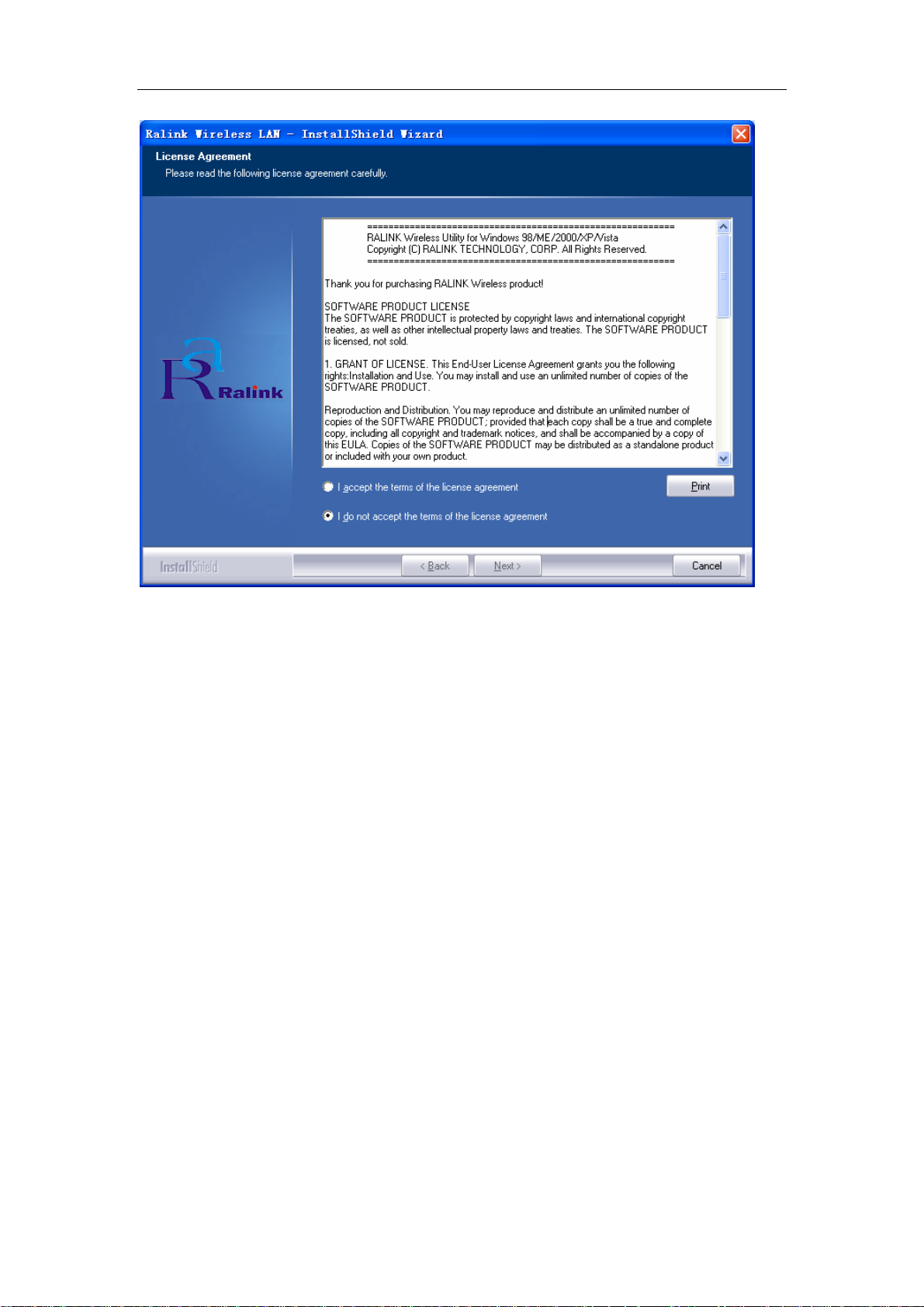
1. Insert the Resource CD into the CD/DVD-ROM drive of your computer; then
execute Setup.exe to install the driver. The system will operate automatically, and
the License Agreement dialog box as shown in Figure 2-1 will appear on the
screen.
- 4 -
Page 5
OEM installation Manual
Figure 2-1 License Agreement
Please read all the license agreement thoroughly and select Yes in case you accept
the license agreement, then click Next >.
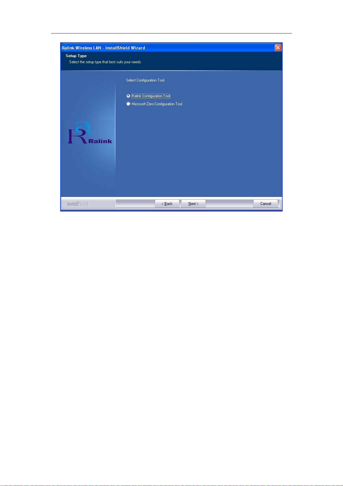
2. The Setup Type dialog box as shown in Figure 2-2 appears on the screen, you
can choose either using Ralink Configuration Tool or Microsoft Zero
Configuration Tool to configure your new IEEE 802.11b/g/n USB WLAN
module. However, it is recommended to select Ralink Configuration Tool to
configure the module as it provides fully access to all functions of the module. If
you prefer to use the wireless configuration tool provided by Windows XP or
Vista, please select Microsoft Zero Configuration Tool. Then click Next to
continue.
- 5 -
Page 6
OEM installation Manual
Figure 2-2 Select Configuration Tool in the Setup Type
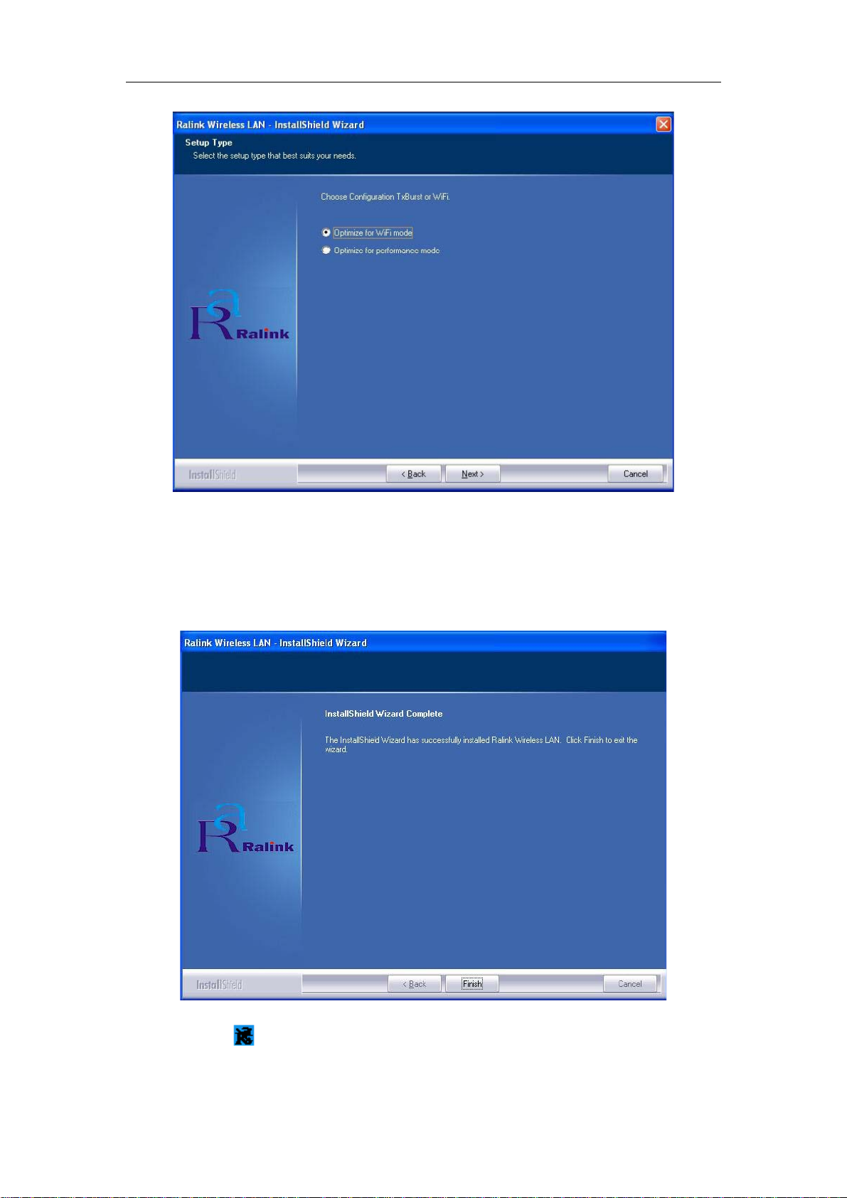
3. You will then be asked to select the wireless performance modes, Optimize for
WiFi mode or Optimize for performance mode, as shown in Figure 2-3. If
you want to enhance wireless performance, please select Optimize for
performance mode. In this mode, the data transfer rate will be enhanced, but
your wireless compatibility may not be guaranteed. For example, the WLAN
module may not be able to communicate with older wireless access point which
only supports IEEE 802.11b or IEEE 802.11g standards. In case you only plan
for setup wireless connectivity with 802.11 Draft-N access points or routers, you
can select this mode for enhancing the overall performance. If you want to keep
compatibility and communicate with older wireless access points or routers,
please select Optimize for WiFi Mode. And click the Next.
- 6 -
Page 7
OEM installation Manual
Figure 2-3 choose Configuration TxBurst or WiFi
4. Please waiting for a moment and let the computer runs automatically to install the
driver. The screen of Figure 2-4 will then appear after the driver has been
installed successfully. Click the Finish to complete the installation.
Figure 2-4 Install Shield Wizard Complete
5. A new icon
will appear at the lower-right corner of your computer after driver
installation. If you put the mouse cursor on top of the icon, a pop up message
- 7 -
Page 8

OEM installation Manual
box will indicate to you that the WLAN module does not exist.
6. Please plug the WLC312NR WLAN module into your PC for the hardware
installation. If you want to understand the detail hardware installation
instructions, please refer to next section - Hardware Installation.
2.2.2 Hardware Installation
After successfully installation of the software driver, please plug the WLC312NR
WLAN USB module into your PC for WLAN card hardware installation. The OS
will detect the module and find the appropriate driver automatically (In case it does
not, please follow the setup steps again as despite in Section 2.2.1) and the the icon
will appear in your system icon box.
Figure 2-5 select the configuration of the WLAN module
When you want to configure your WLAN module, please right click the icon , and
a popup menu of Figure 2-5 will appear. You can click Launch Config Utilities to
start the configuration. If you want to close configuration utility, please click Exit.
Note: If you want to stop configuration utility by clicking the Exit, you’ll not be
able to maintain the current wireless link connectivity to the access.
You can start configuration utility again by clicking Ralink Wireless Utility icon
from Start -> All Programs -> Ralink Wireless -> Ralink Wireless Utility.
2.3 Connect to Wireless Access Point
This section shows you how to configure the WLC312NR WLAN module in order to
getting connection to a wireless access point. There are two kinds of ways that you
can carry out this task:
- 8 -
Page 9

OEM installation Manual
• Using Ralink Configuration Utility to connect the wireless access point.
• Using Windows built-in Windows Zero Configuration Utility to connect
the wireless access point.
2.3.1 Using Ralink Configuration Utility
Below instructions show you how connect to the wireless access point using Ralink
Configuration Utility:
1. Right-click the Ralink configuration utility icon located at low-right corner of
your PC, click Launch Config Utilities, Figure 2-5 will appear.
2. To add a new connection profile, you can either
• Create a new profile or
• Modify a profile from an existing wireless access point or wireless device.
- 9 -
Page 10

OEM installation Manual
Figure 2-6 Profile setting
To create a new profile, please click the tab Profile, and select the button Add and
then Edit to create and edit new profile:
● Profile Name - Up to 32 alphanumerical characters and symbols, space is not
allowed in this field.
● SSID - The SSID of the wireless access point or wireless device you selected will
be displayed here. In case the SSID of access point or wireless device is not available,
you are requested to input the SSID manually.
● PSM - Please select CAM (constantly Awake Mode) in case you want to keep the
wireless radio activity even if there is no data transfer. Or you can select the PSM
(Power Saving Mode) while the radio activity will be switched off when there is no
data transfer. It’s recommended to choose ‘PSM’ if you’re using this WLAN card
with notebook computer in order to save the battery power.
● Network Type - Select network type (‘Ad Hoc’ or ‘Infrastructure’). If you’re
adding a profile from an existing access point or wireless device, it’s automatically
selected
● Preamble - This option is only available when the network type is ‘Ad hoc’. You
can select Auto or Long Preamble. Please select Auto if you don’t know what it is.
● RTS - Threshold Check the box and you can set RTS threshold manually here. Do
not modify default setting unless you know what it is.
● Fragment Threshold - Check the box and you can set fragment threshold manually
here. Do not modify default setting unless you know what it is.
You can also add a connection to the wireless access point or wireless by clicking the
tab Network, and select the button Add to Profile as Figure 2-7 to add a new profile,
and set the parameter for the new profile.
You can click the tab Auth.\ Encry whose figure as figure 2-7 to set the encryption
and authentication settings.
● Authentication Type - Select the authentication type of the wireless access point or
wireless device you wish to connect. If you’re adding a profile from an existing
access point or wireless device, the value will be selected automatically, and please do
not modify it. If you select LEAP
, the following message will be displayed. Please
input LEAP identity, password, domain name, and select encryption type. You can
click the button Show Password so the password you inputted will be displayed as
you type, but not replace by asterisk.
● Encryption-Select the encryption type of the wireless access point or wireless
device you wish to connect. If you’re adding a profile from an existing access point or
wireless device, the value will be selected automatically, and please do not modify it.
● WPA Preshared Key-Input WPA preshared key here. If encryption is not, or you
select ‘WEP’ as encryption type, this field will be disabled and grayed out.
● WEP Key-You can select key type (Hex or ASCII) and input WEP key here. If
- 10 -
Page 11

OEM installation Manual
encryption is not enabled, or you select ‘WPA’ as encryption type, this field will be
disabled and grayed out.
● Show Password-Check this box and all passphrases or security keys
you inputted will be displayed as you type, but not replace your input with asterisk.
● 802.1x-Enable 802.1x wireless authentication
Figure 2-7 setting for Network
3. You can also scan to catch the existing wireless access points.
Configuration utility can scan all wireless access points automatically. Scan
results will be displayed as the Figure 2-7, please check if the wireless access
point with the SSID (the name of wireless access point) you preferred is shown
here. If the wireless access point you wish to connect does not show here, please
click Rescan to try again, until the one you preferred is displayed.
● SSID - Service Set IDentifier is the identity of wireless access point. You can
think SSID is the name of access point.
● Channel - Shows the channel number that access point or wireless device being
used.
● Signal - Shows the signal strength of access point or wireless device. The larger
number, the better radio strength, which often means you’re not too far from that
- 11 -
Page 12

OEM installation Manual
access point or wireless device.
4. Click the wireless access point or network device been selected, it will be
highlighted as the Figure 2-7, then click Connect.
If the access point be selected does not enable encryption (The content of Encryption
field of the access point you selected None, you’ll be connected to this wireless
access point within one minute). Please jump to next step. If the access point you
selected enables encryption, please proceed to next step.
5. If the wireless access point uses encryption, please setting in the dialog box as
Figure 2-7, you have to input WEP passphrase or WPA preshared key. Please
ask the owner of the wireless access point you want to connect, and input the
correct passphrase / preshared key here, then click OK.
6. You’ll see Connected <-> SSID (SSID is the SSID of the wireless access point or
wireless device you connected to) message displayed at lower-left corner of
configuration utility as the Figure 2-8. Congratulations, you have successfully
connected to the access point or wireless device you be selected.
Figure 2-8 the status of Congratulations
7. Open the tab Advanced as the Figure 2-9, you can set some advanced setting in
here.
● Wireless mode - Select wireless operation mode, available options are 2.4G.
- 12 -
Page 13

OEM installation Manual
● Enable Tx BURST - Check this box to accelerate the data transmit rate, It may not
work with all wireless access point and wireless devices.
Figure 2-9 The setting for Advanced
● Enable TCP Window Size - Check this box and the configuration utility will
adjust TCP window size automatically, to get better performance. It should be safe for
most of wireless environments, but if you found some problem on data transfer,
uncheck this box.
● Fast Roaming at - Check this box and you can adjust the threshold of when this
wireless network card should switch to another wireless access point with better
signal quality. Only adjust value when you understand what it means.
● Select Your Country Region Code - Select the country / region code of the place
you’re living. Different country / region has different regulations on wireless devices,
and it’s forbidden to use certain channel (radio frequency) in some countries or
regions. The operating frequency channel will be restricted to the country / region
user located before importing.
● Show Authentication Status Dialog - When your computer is being authenticated
by wireless authentication server, a dialog window with the process of authentication
will appear. This function is helpful to find out the problem when you can not be
authenticated, and you can provide this information to authentication server’s
administrator for debugging purpose.
● Enable CCX - Enable Cisco Compatible eXtensions CCX is a wireless feature
developed by Cisco used to improve the wireless performance with CCX compatible
wireless devices. Check this box if you need to connect to CCX-compatible wireless
devices.
● Turn on CCKM - Check this box to enable CCKM (Cisco Centralized Key
Management), which enables wireless clients to roam between CCKM-enabled access
points in very short time.
● Enable Radio Measurements - When you’re connecting to CCX-compatible
- 13 -
Page 14

OEM installation Manual
access point, check this box to enable radio measurement function to improve
wireless connectivity.
● Non-Serving Channel Measurements Limit -When you’re connecting to
CCX-compatible access point, check this box to enable measurement on unused radio
channels to improve wireless connectivity. Limit the time used for said measurement
to a certain time. Default value is 250.
8. Open the tab Statistic as the Figure 2-10 Statistics of transmit and receive, you
can click Reset Counter to reset the statistics of all items back to 0. Click OK to
close the window.
Figure 2-10 Statistics of transmit and receive
● Transmit – To appear the Statistic of the frames transmitted successfully, frames
retransmitted successfully, frames fail to receive ACK after all retries RTS frames
successfully receive CTS and RTS frames fail to receive CTS.
● Receive – To display the statistic of frames received successfully, frames received
with CRC error, frames dropped due to out-of-resource and duplicate frames received.
● Reset Counter – Reset the statistics of all items.
9. The functions of WMM, WPS and Radio On/Off are:
WMM -> Display the WMM setup status
WPS -> WPS functional and parameter setting parameter
Radio On/Off -> Button to turn ON/OFF the WLAN module.
10. Open the tab About as the Figure 2-11, the tab provides you the information
about version numbers of configuration utility, firmware, and other important
information about your wireless network card.
- 14 -
Page 15

OEM installation Manual
Figure 2-11 The information of configuration utility
2.3.2 Using Windows Zero Configuration
Windows XP and Vista has a built-in wireless network configuration utility, called as
the ‘Windows Zero Configuration’ (WZC). You can also use WZC to configure your
wireless network parameter:
1. Right-click Ralink configuration utility icon as the Figure 2-12 and select Use
Zero Configuration as Configuration utility.
Figure 2-12 select WZC to configure your wireless network
2. Click the button Start (should be located at the bottom-left corner of windows
desktop), select Start -> Control Panel -> Network and Internet Connections ->
network Connection
3. Right-click Wireless Network Connection (it may have a number as suffix if you
have more than one wireless adapter, please make sure you right-click the Ralink
802.11n Wireless LAN Card, then select View Available Wireless Networks.
- 15 -
Page 16

OEM installation Manual
Figure 2-13 Setting for wireless Network Connection
4. All wireless access points in proximity will be displayed here. If the access point
you want to use is not displayed here, please try to move your computer closer to the
access point, or you can click Refresh network list to rescan access points. Click the
access point you want to use if it’s shown, then click Connect.
Figure 2-14 Choose a wireless network to connect
5. If the access point is protected by encryption, you have to input its security key or
passphrase here. It must match the encryption setting on the access point. If the access
point you selected does not use encryption, you’ll not be prompted for security key or
passphrase.
- 16 -
Page 17

OEM installation Manual
Figure 2-15 setting for security key or passphrase
7. If you can see Connected message, the connection between your computer and
wireless access point is successfully established.
Figure 2-16 wireless network have been connect
- 17 -
Page 18

OEM installation Manual
Chapter 3: Regulatory information
3.1 FCC Information to User
This product does not contain any user serviceable components and is to be used with approved
antennas only.
Any changes or modifications not expressly approved by the party responsible for compliance
could void the user's authority to operate this equipment.
3.2 FCC Guidelines for Human Exposure
Warning:
The antenna used for this transmitter must be installed to provide a separation distance of at least
20 cm from all persons and must not be co-located or operating in conjunction with any other
antenna or transmitter.
3.3 FCC Electronic Emission Notices
This device complies with part 15 of the FCC Rules. Operation is subject to the
following two conditions:
1. This device may not cause harmful interference
2. This device must accept any interference received, including interference that may
cause undesired operation.
FCC statement:
This equipment has been tested and found to comply with the limits for a Class B digital device,
pursuant to Part 15 of the FCC Rules. These limits are designed to provide reasonable protection
against harmful interference in a residential installation. This equipment generates, uses and can
radiate radio frequency energy and, if not installed and used in accordance with the instructions,
may cause harmful interference to radio communications. However, there is no guarantee that
interference will not occur in a particular installation. If this equipment does cause harmful interference
to radio or television reception, which can be determined by turning the equipment off and on,
the user is encouraged to try to correct the interference by one of the following measures:
Reorient or relocate the receiving antenna.
Increase the separation between the equipment and receiver.
Connect the equipment into an outlet on a circuit different from that to which the receiver is connected.
Consult the dealer or an experienced radio/TV technician for help.
3.4 OEM Installation Guide
This device is intended only for OEM integrators under the following conditions:
(1) The antenna must be installed such that 20 cm is maintained between the antenna
and users;
(2) The transmitter module may not be co-located with any other transmitter or
antenna;
(3) For all products market in US, OEM has to limit the operation channels in CH1 to
CH11 for 2.4G band. OEM shall not supply any tool or info to the end-user
regarding to Regulatory Domain change. As long as 3 conditions above are met,
further transmitter test will not be required. However, the OEM integrator is still
responsible for testing their end-product (host of this device) for any additional
compliance requirements required.
IMPORTANT NOTE: In the event that these conditions can not be met (for example
certain laptop configurations or co-location with another transmitter), then the FCC
authorization is no longer considered valid and the FCC ID can not be used on the
- 18 -
Page 19

OEM installation Manual
final product. In these circumstances, the OEM integrator will be responsible for
re-evaluating the end product (including the transmitter) and obtaining a separate FCC
authorization.
End Product Labeling
This transmitter module is authorized only for use in device where the integrated
antenna may be installed such that 20 cm may be maintained between the antenna and
users. The final end product must be labeled in a visible area with the following:
“Contains FCC ID: Q72WLC312NR”.
End Product Manual Information To the End User
The OEM integrator has to be aware not to provide information to the end user
regarding how to install or remove this RF module in the user’s manual of the end
product. The user manual for end users must include the following information in a
prominent location “IMPORTANT NOTE: To comply with FCC RF exposure
compliance requirements, the antenna used for this transmitter must be installed to
provide a separation distance of at least 20cm from all persons and must not be
co-located or operating in conjunction with any other antenna or transmitter.”
IMPORTANT NOTE
FCC RF Radiation Exposure Statement: This equipment complies with FCC RF
radiation exposure limits set forth for an uncontrolled environment. This device and
its antenna must not be co-located or operating in conjunction with any other antenna
or transmitter.
RF Exposure Info (For mobile configuration)
To comply with FCC RF exposure compliance requirements, this grant is applicable
to only Mobile Configurations. The antennas used for this transmitter must be
installed to provide a separation distance of at least 20 cm from all persons and must
not be co-located or operating in conjunction with any other antenna or transmitter.
3.5 Antenna Specification
This device is certified as modular radio form with the build-in internal PCB antenna. Change to
other type of antenna requires re-evaluation/ certification.
- 19 -
Page 20

OEM installation Manual
Chapter 4: Technical Specifications
Appendix A: Specifications
Standards
IEEE802.11b, 802.11g, 802.11n Draft
Operating Frequency
Channel Bandwidth
Protocols
Security
Receive Sensitivity
Operating Voltage
Transmit Output Power
Bus Interface
2.4 GHz ~ 2.46 GHz ISM band
20/40MHz Support
802.11b: CCK, QPSK, BPSK
802.11g: OFDM
Draft-11n: BPSK, QPSK, 16-QAM, 64-QAM
802.11i – WEP 64/128, WPA & WPA2.
Cisco CCX V1.0, V2.0 & V3.0 Compliant
54Mbps@-65dbm (Typical)
Draft-N@-61dbm (Typical)
5V DC ± 5%
= +14.5dBm ±5% @ OFDM 6 & 54Mbps mode
= +17.5dBm ±5% @ DSSS 1 & 11Mbps mode
= +12.5dBm ±5% @ 802.11n mode
A-type USB 2.0 Connector
- 20 -
Page 21

OEM installation Manual
Appendix B: Glossary
* 802.11b - The 802.11b standard specifies a wireless product networking at 11 Mbps
using direct-sequence spread-spectrum (DSSS) technology and operating in the
unlicensed radio spectrum at 2.4GHz, and WEP encryption for security. 802.11b
networks are also referred to as Wi-Fi networks.
* 802.11g - specification for wireless networking at 54 Mbps using direct-sequence
spread-spectrum (DSSS) technology, using OFDM modulation and operating in the
unlicensed radio spectrum at 2.4GHz, and backward compatibility with IEEE 802.11b
devices, and WEP encryption for security.
* Ad-hoc Network - An ad-hoc network is a group of computers, each with a wireless
adapter, connected as an independent 802.11 wireless LAN. Ad-hoc wireless
computers operate on a peer-to-peer basis, communicating directly with each other
without the use of an access point. Ad-hoc mode is also referred to as an
Independent Basic Service Set (IBSS) or as peer-to-peer mode, and is useful at a
departmental scale or SOHO operation.
* DSSS (Direct-Sequence Spread Spectrum) - DSSS generates a redundant bit
pattern for all data transmitted. This bit pattern is called a chip (or chipping code).
Even if one or more bits in the chip are damaged during transmission, statistical
techniques embedded in the receiver can recover the original data without the need
for retransmission. To an unintended receiver, DSSS appears as low power
wideband noise and is rejected (ignored) by most narrowband receivers. However, to
an intended receiver (i.e. another wireless LAN endpoint), the DSSS signal is
recognized as the only valid signal, and interference is inherently rejected (ignored).
* FHSS (Frequency Hopping Spread Spectrum) - FHSS continuously changes (hops)
the
carrier frequency of a conventional carrier several times per second according to a
pseudo-random set of channels. Because a fixed frequency is not used, and only the
transmitter and receiver know the hop patterns, interception of FHSS is extremely
difficult.
* Infrastructure Network - An infrastructure network is a group of computers or other
devices, each with a wireless adapter, connected as an 802.11 wireless LAN. In
infrastructure mode, the wireless devices communicate with each other and to a
wired network by first going through an access point. An infrastructure wireless
network connected to a wired network is referred to as a Basic Service Set (BSS). A
set of two or more BSS in a single network is referred to as an Extended Service Set
(ESS). Infrastructure mode is useful at a corporation scale, or when it is necessary to
connect the wired and wireless networks.
* Spread Spectrum - Spread Spectrum technology is a wideband radio frequency
technique developed by the military for use in reliable, secure, mission-critical
communications systems. It is designed to trade off bandwidth efficiency for reliability,
integrity, and security. In other words, more bandwidth is consumed than in the case
of narrowband transmission, but the trade off produces a signal that is, in effect,
- 21 -
Page 22

OEM installation Manual
louder and thus easier to detect, provided that the receiver knows the parameters of
the spread-spectrum signal being broadcast. If a receiver is not tuned to the right
frequency, a spread-spectrum signal looks like background noise. There are two
main alternatives, Direct Sequence Spread Spectrum (DSSS) and Frequency
Hopping Spread Spectrum (FHSS).
* SSID - A Service Set Identification is a thirty-two character (maximum) alphanumeric
key identifying a wireless local area network. For the wireless devices in a network to
communicate with each other, all devices must be configured with the same SSID.
This is typically the configuration parameter for a wireless PC card. It corresponds to
the ESSID in the wireless Access Point and to the wireless network name.
* WEP (Wired Equivalent Privacy) - A data privacy mechanism based on a 64-bit or
128-bit or 152-bit shared key algorithm, as described in the IEEE 802.11 standard.
* Wi-Fi - A trade name for the 802.11b wireless networking standard, given by the
Wireless Ethernet Compatibility Alliance (WECA, see http://www.wi-fi.net), an
industry standards group promoting interoperability among 802.11b devices.
* WLAN (Wireless Local Area Network) - A group of computers and
associated devices communicate with each other wirelessly, which
network serving users are limited in a local area.
* WPA (Wi-Fi Protected Access) - A wireless security protocol use TKIP (Temporal Key
Integrity Protocol) encryption, which can be used in conjunction with a RADIUS server.
THE END
- 22 -
 Loading...