

Page 1

User Manual
Chung Nam Electronics (CNE)
IEEE 802.11b/g USB WLAN Card
(Model #: WLC-301GRSM)
User Manual
Version 1.0
Nov 2008
1
Page 2

User Manual
Table of Contents
Chapter 1 Introduction ................................................................................................................. 3
1.1 Product ........................................................................................................................... 3
1.2 Main Features................................................................................................................. 3
1.3 LED Status ..................................................................................................................... 4
Chapter 2 Installation Procedure.................................................................................................. 5
2.1 Software Installation ...................................................................................................... 5
2.2 Hardware Installation..................................................................................................... 8
2.3 Profile............................................................................................................................. 8
2.4 Link Status ................................................................................................................... 12
2.6 Statistics ....................................................................................................................... 14
2.7 Advanced...................................................................................................................... 15
Chapter 3 Configuration ............................................................................................................ 15
Chapter 4 Regulatory Information ............................................................................................. 17
4.1 FCC Information to User ............................................................................................. 17
4.2 FCC Guidelines for Human Exposure ......................................................................... 17
4.3 FCC Electronic Emission Notices ............................................................................... 17
Chapter 5 Technical Specifications............................................................................................ 19
2
Page 3

User Manual
Chapter 1 Introduction
1.1 Product
The 54M Wireless USB Card is a USB 2.0 pen-size wireless dongle supporting IEEE
802.11b/g 2.4GHz radio operation. It provides high-speed wireless connection with data rate
up to 54Mbps. Additionally, wireless roaming allows the user to move among different AP
without losing the current connection. The adapter provides excellent security features
including:TKIP, AES, WPA, and up to 128 bit WEP encryption security make the network
almost impenetrable.
Featuring high performance transmission rates, simple installation and adaptability, as well as
strong security the CNE Wireless USB Adapter is the perfect solution for small office and
home needs.
1.2 Main Features
● Complies with IEEE802.11g, IEEE802.11b standards
● Supports WPA data security, IEEE802.1x authentication, TKIP/AES encryption,
64/128-bitWEP encryption
● Supports 54/48/36/24/18/12/9/6Mbps or 11/5.5/2/1Mbps wireless LAN data transfer rates
● Provides USB interface
● Supports Ad-Hoc and Infrastructure modes
● Supports roaming between access points when configured in Infrastructure mode
● Eases configuration and provides monitoring information
● Supports Windows 98SE, Me, 2000, XP
● Internal Antenna
3
Page 4

User Manual
1.3 LED Status
A green LED indicates Link/Act status. It blinks at green light when sending and receiving
data.
4
Page 5
User Manual
Chapter 2 Installation Procedure
2.1 Software Installation
2.1.1 Overview
The Adapter’s Setup Wizard will guide you through the installation procedure for Windows
98SE, Me, 2000 and XP. The Setup Wizard will guide you install the Utility and drivers.
If you install the hardware before the software, you will be prompted “Found New Hardware
Wizard”, click the Cancel button, and run the Setup Wizard program on the CD-ROM.
The Setup steps for Windows 98SE, Me, 2000 and XP are very similar. The following setup
steps are for windows 2000.
2.1.2 Software Installation for Windows 2000
1. Insert the Resource CD into your CD-ROM drive, click the Start button and choose Run.
In the field that appears, enter F:\XXX\Setup.exe (if “F” is the letter of your CD-ROM
drive; XXX presents the setup program path, which is labeled on the Resource CD), Figure
2-1 should then appear.
5
Page 6
User Manual
Figure 2-1 Preparing Setup
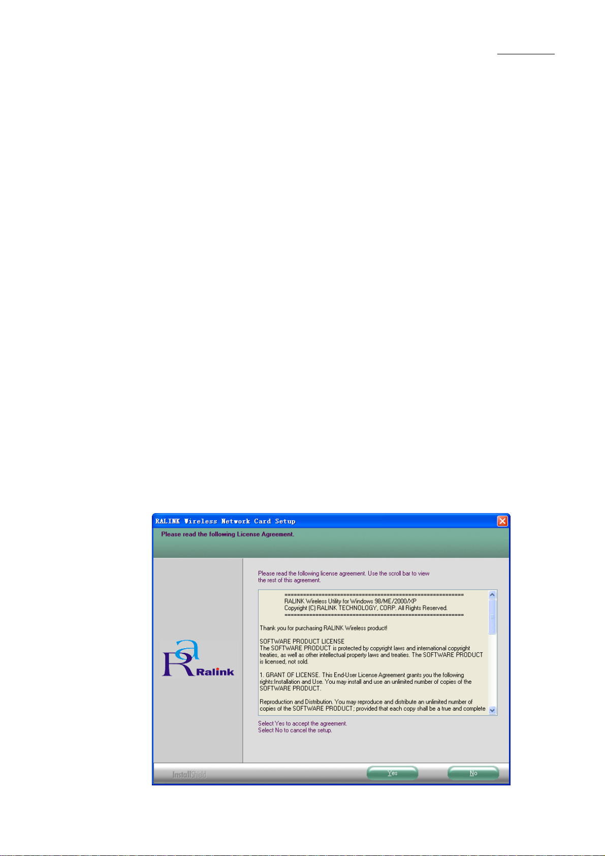
2. You will see a warning box shown in Figure 2-1, click the No button to end the installation.
Otherwise, click the Yes button to install driver, the Setup Wizard will display a screen
similar to that shown in Figure 2-2 after a moment.
Figure 2-2 Start Setup
User Guide
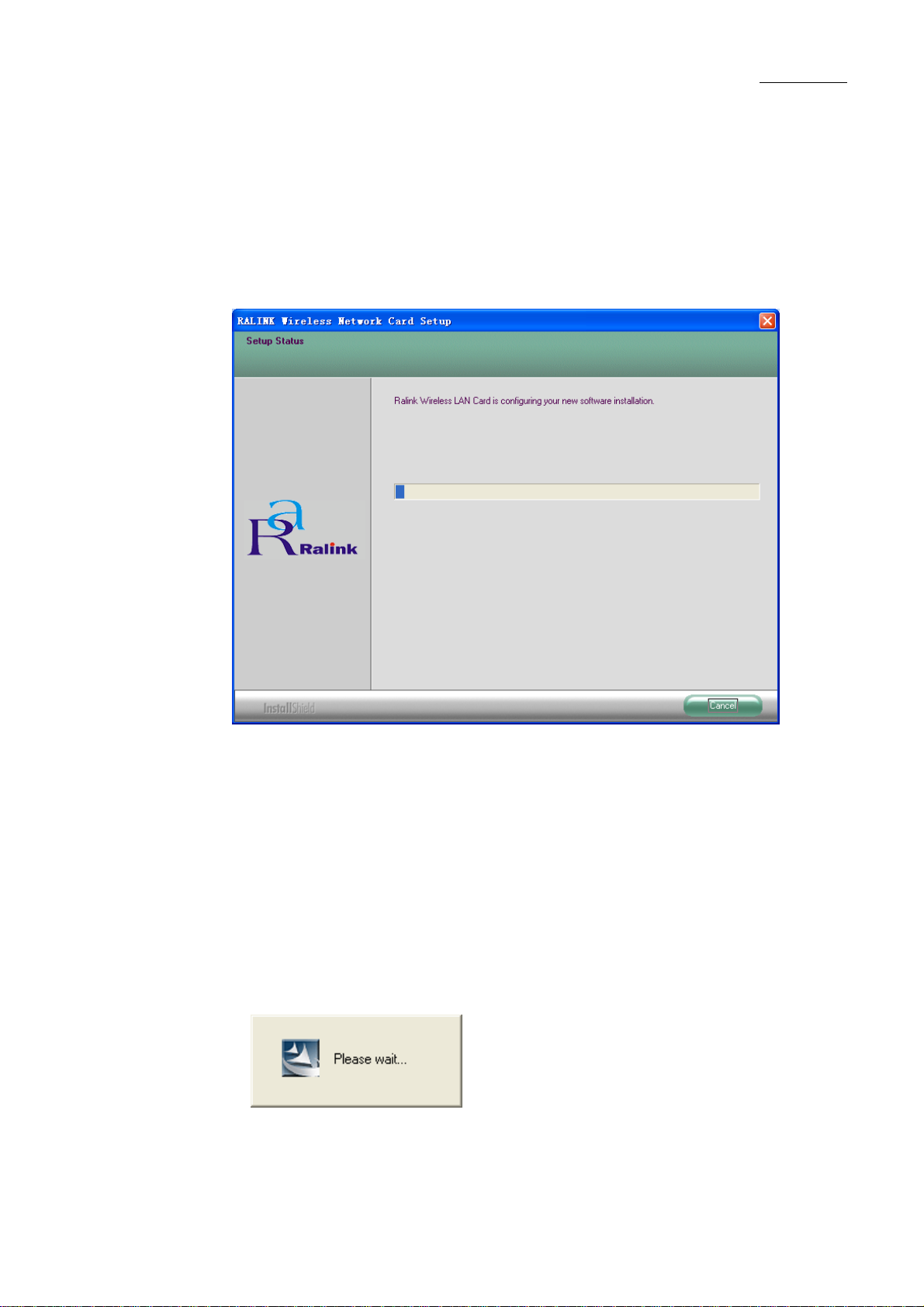
3. To continue, please waiting for running automatically for a moment, Figure 2-2. Click the
Cancel button to end the Installation.
4. The soft install automatically in the operating system, and appear a dialog box Figure 2-3.
Now, only a thing which you can do is Waiting!
6
Page 7
User Manual
Figure 2-3 waiting state dialog box
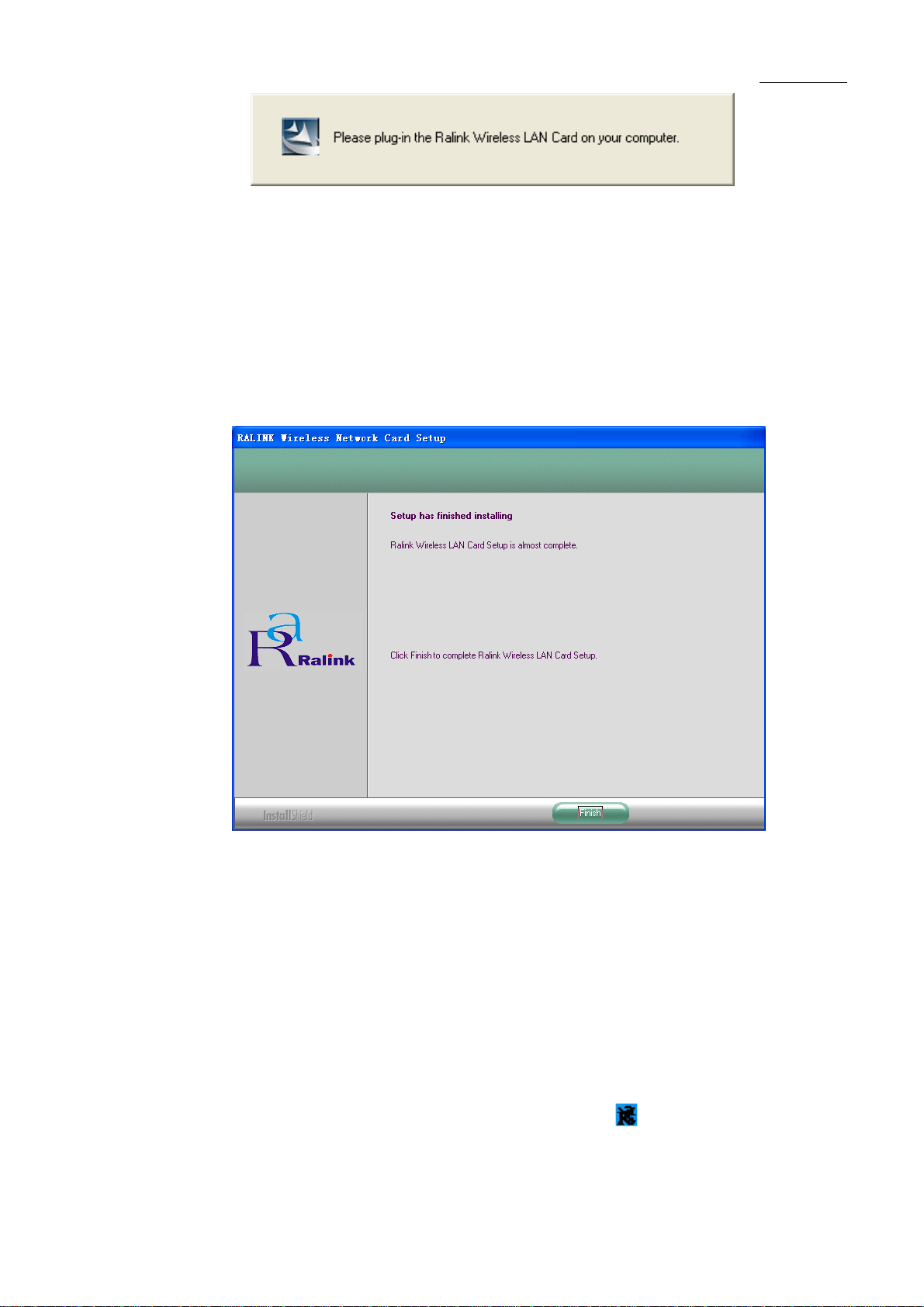
5. After the files have been successfully installed, the screen in Figure 2-4 will appear. Click
the Finish button to finish the wizard.
Figure 2-4 Finish installing
6. After installing the software, Please plug the adapter into your PC. If you need instructions
as to how to do this, please refer to next section - Hardware Installation. If you have
plugged it into you PC already, please unplug it and plug it back in. The OS will
automatically detect the adapter and automatically setup the driver for the adapter. If it does
not, please follow the setup steps to finish the driver installation.
After installing the driver successfully, you should see an icon appear in your system icon
box.
7
Page 8

User Manual
2.2 Hardware Installation
1. Connect one end of the USB cable to the Adapter.
2. Connect the other end of the USB cable to the USB port on your computer. Because the
Adapter gets its power from the host, there is no external power supply. The LED should light
up when the Adapter is plugged in and the PC is on.
2.3 Profile
Click the Profile tab of the utility and the Profile screen will appear, Figure 2-1. The Profile
screen provides tools to:
● Add a Profile
● Delete a profile
● Edit a profile
● Activate a profile
8
Page 9

User Manual
Figure 3-1 Profile Tab
To create a new profile, click the Add button on the Profile tab, the Profile configuration
screen will appear as shown in Figure 2-2.
To edit a profile, highlight the desired profile name on Profile Name list, and click the Edit
button, the Profile configuration screen will appear shown in Figure 2-1.
To delete a profile, highlight the desired profile name on Profile Name list, and click the
Delete button.
To switch to another profile, highlight the desired profile name on Profile Name list, and
click the Activate button.
* Note:
Do not forget to click the Apply button when you create a new profile for connection.
To add a new configuration profile, click Add button on the Profile Management tab. To
modify a configuration profile, select the configuration from the Profile list and click Edit. The
Profile Management dialog box will display a screen similar to that shown in Figure 3-2.
1. Edit the Configuration tab
9
Page 10

User Manual
Figure 3-2 Add Profile – configuration
● Profile Name - Identifies the configuration profile. This name must be unique. Profile names
are not case-sensitive.
● SSID - The IEEE 802.11 wireless network name. This field has a maximum limit of 32
characters.
● PSM (Power Save Mode)
►CAM (Constantly Awake Mode) – Continuous Access Mode.
► PSM (Power Saving Mode) - Power Saving mode.
● Network Type – Displays the wireless mode, either Ad-hoc or Infrastructure mode.
● Preamble – Specifies the preamble setting in 802.11b. The default setting is Auto Switch
(access point mode), which allows both short and long headers in the 802.11b frames. The
adapter can only use short radio headers if the access point supports and uses them.
● RTS Threshold – Default is 2312.
10
Page 11

User Manual
● Fragment Threshold – Default is 2312.
● Ad-hoc mode – Displays the wireless mode, either Only 802.11B or 802.11B/G mode.
● Channel – Shows the current channel in use. This field determines which operating
frequency will be used.
2. Edit the Authentication and Security tab
Figure 3-3 Add Profile – configuration
● Authentication Type – Three options, Open System, Shared-Key System or LEAP.
● 802.1x Setting – It enables when Authentication Type is setting to WPA.
● Encryption – Displays which encryption type that the driver is using. When you select
Open System, Shared-Key System as Network Authentication, there are two options: WEP
and None. If you select WPA-PSK as Network Authentication, there are TKIP and AES
options instead of WEP and None.
● Wep Key – Key #1, Key #2, Key #3, Key #4, the Key groups. You can enter 10 hexadecimal
digits (any combination of 0-9, a-f, A-F) or 5 ASCII characters for 64-bit (also called 40bits)
11
Page 12

User Manual
encryption. You can enter 26 hexadecimal digits (any combination of 0-9, a-f, A-F) or 13
ASCII characters for 128-bit (also called 104bits) encryption.
2.4 Link Status
The Link Status tab Figure 3-4 displays the adapter's current status.
Figure 3-4 Link Status
The following table describes the items found on the Network Status screen.
● Status - Shows whether the station is connected to the wireless network, if not connected,
display RF is closed; if connected, display AP name and BSSID.
● Extra Info - Shows link status and the current channel in use.
● Link Speed - Shows the current max Transfer rate, unit is Mbit/sec.
● Throughput - Displays Tx and Rx rate, unit is Kbits/sec.
12
Page 13

User Manual
● Link Quality - Shows the quality of the signal.
● Signal Strength - Shows the strength of the signal.
2.5 Site Survey
Click the Site Survey tab of the Utility and the Site Survey screen will appear, Figure 3-5. On
the Site Survey screen you can scan the Available Infrastructure and Ad Hoc Networks.
Figure 3-5 Site Survey tab
Click the Rescan button to refresh the list at any time. Highlight an SSID and click the
Connect button to connect to an available network.
13
Page 14

User Manual
2.6 Statistics
The Statistics tab as Figure 3-6 shows receiving and transmitting statistical information for the
following receive and transmit diagnostics for frames received by or transmitted to the wireless
network adapter.
Click the Reset Counter button to reset the count of the statistics information.
Figure 3-6 Statistics tab
14
Page 15

2.7 Advanced
User Manual
15
Page 16

User Manual
Chapter 3 Configuration
CNE 802.11b/g Wireless USB Adapter can be configured by its utility. This section describes
how to configure your Wireless USB Adapter for wireless connectivity on your Wireless Local
Area Network (WLAN) and use the data security encryption features.
After the Adapter's driver and utility has been installed, the adapter’s tray icon or will
appear in your system tray. It means the utility is running on your system. If the utility does not
run, you can run the utility by clicking: Start> Program>RaLink Wireless> RaLink
Wireless Utility. If the icon still does not appear, the driver or utility may be installed
incorrectly or the adapter is unplugged, please try again.
Icon means the connection has been established. Icon means there is no connection.
Double-click the icon and the configuration screen of the utility will appear. You can also
run the utility by clicking: Start> Program>RaLink Wireless> RaLink Wireless Utility.
The utility provides a complete and easy to use set of tools to:
● Display current status information
● Edit and add configured profiles
● Display current diagnostics information
The section below introduces these above capabilities.
* Note:
If your OS is Windows XP, you can use Windows XP to configure the wireless network
settings. (To use this function, you must upgrade the OS with sp1).
If you want to use Windows XP to configure wireless network settings, just exit the utility.
Right-click the icon at the bottom of the screen, and click Exit to exit the utility.
16
Page 17

User Manual
Chapter 4 Regulatory Information
4.1 FCC Information to User
FCC Caution: Any changes or modifications not expressly approved by the party responsible for
compliance could void the user's authority to operate this equipment.
4.2 FCC Guidelines for Human Exposure
FCC RF exposure statement: This equipment complies with FCC radiation exposure limits set
forth for an uncontrolled environment. End users must follow the specific operating instructions
for satisfying RF exposure compliance. To maintain compliance with FCC RF exposure
compliance requirements please follow operation instructions as document in this manual.
This device has been tested for compliance with FCC RF Exposure (SAR) limits in the typical
laptop computer configuration and this device can be used in desktop or laptop computers with
USB slots. Other applications like handheld PDAs (personal digital assistants) or similar device
has not been verified and may not compliance with related RF exposure rule and such use
should be prohibited. This device with its antenna must not be co-located or operated in
conjunction with any other antenna or transmitter.
This EUT is compliance with SAR for general population/uncontrolled exposure limits in
ANSI/IEEE C95.1-1999 and had been tested in accordance with the measurement methods and
procedures specified in OET Bulletin 65 Supplement C.
4.3 FCC Electronic Emission Notices
This device complies with part 15 of the FCC Rules.
Operation is subject to the following two conditions:
1. This device may not cause harmful interference
2. This device must accept any interference received, including interference that may cause
undesired operation.
This device and its antenna(s) must not be co-located or operating in conjunction with any
other antenna or transmitter.
17
Page 18

User Manual
This equipment has been tested and found to comply with the limits for a class B digital device,
pursuant to part 15 of the FCC Rules. These limits are designed to provide reasonable protection
against harmful interference in a residential installation.
This equipment generates, uses and can radiate radio frequency energy and, if not installed and
used in accordance with the instructions, may cause harmful interference to radio
communications. However, there is no guarantee that interference will not occur in a particular
installation. If this equipment does cause harmful interference to radio or television reception,
which can be determined by turning the equipment off and on, the user is encouraged to try to
correct the interference by one or more of the following measures:
---Reorient or relocate the receiving antenna.
---Increase the separation between the equipment and receiver.
---Connect the equipment into an outlet on a circuit different from that to which the receiver is
connected.
---Consult the dealer or an experienced radio/TV technician for help.
18
Page 19

Chapter 5 Technical Specifications
Appendix A: Specifications
General
Interface A-type USB 2.0 Connector
Standards IEEE 802.11b; IEEE 802.11g
Operating System Windows 98SE, ME, 2000, XP
User Manual
Transmission
Distance
Frequency 2.412~ 2.462 GHz
Sensitivity
Spread Spectrum Direct Sequence Spread Spectrum (DSSS)
Radio Data Rate
Modulation 11g OFDM , 11b CCK/DSSS
Media Access
Protocol
Data Security
Working
Temperature
In door up to 100m, out door up to 300m (It is limited to
the environment).
54M -70dBm
11M -83dBm
Wireless
54/48/36/24/18/12/9/6 Mbps 11g OFDM,11/5.5/2/1 Mbps
11b DSSS,(Auto Rate Sensing)
CSMA/CA with ACK
WPA, 64/128 bit WEP, TKIP/AES, IEEE 802.1X
authentication
Physical Environmental
0℃~55℃ (32℉~104℉)
Storage
Temperature
Humidity
Dimensions 68m (L) x 22.3mm (W) x 9.2mm (H)
-10℃~70℃ (-40℉~158℉)
10%~90% RH, Non-condensing
19
Page 20

User Manual
Appendix B: Glossary
* 802.11b - The 802.11b standard specifies a wireless product networking at 11 Mbps
using direct-sequence spread-spectrum (DSSS) technology and operating in the
unlicensed radio spectrum at 2.4GHz, and WEP encryption for security. 802.11b
networks are also referred to as Wi-Fi networks.
* 802.11g - specification for wireless networking at 54 Mbps using direct-sequence
spread-spectrum (DSSS) technology, using OFDM modulation and operating in the
unlicensed radio spectrum at 2.4GHz, and backward compatibility with IEEE 802.11b
devices, and WEP encryption for security.
* Ad-hoc Network - An ad-hoc network is a group of computers, each with a wireless
adapter, connected as an independent 802.11 wireless LAN. Ad-hoc wireless
computers operate on a peer-to-peer basis, communicating directly with each other
without the use of an access point. Ad-hoc mode is also referred to as an
Independent Basic Service Set (IBSS) or as peer-to-peer mode, and is useful at a
departmental scale or SOHO operation.
* DSSS (Direct-Sequence Spread Spectrum) - DSSS generates a redundant bit
pattern for all data transmitted. This bit pattern is called a chip (or chipping code).
Even if one or more bits in the chip are damaged during transmission, statistical
techniques embedded in the receiver can recover the original data without the need
for retransmission. To an unintended receiver, DSSS appears as low power
wideband noise and is rejected (ignored) by most narrowband receivers. However, to
an intended receiver (i.e. another wireless LAN endpoint), the DSSS signal is
recognized as the only valid signal, and interference is inherently rejected (ignored).
* FHSS (Frequency Hopping Spread Spectrum) - FHSS continuously changes (hops) the
carrier frequency of a conventional carrier several times per second according to a
pseudo-random set of channels. Because a fixed frequency is not used, and only the
transmitter and receiver know the hop patterns, interception of FHSS is extremely difficult.
* Infrastructure Network - An infrastructure network is a group of computers or other
devices, each with a wireless adapter, connected as an 802.11 wireless LAN. In
infrastructure mode, the wireless devices communicate with each other and to a
wired network by first going through an access point. An infrastructure wireless
network connected to a wired network is referred to as a Basic Service Set (BSS). A
set of two or more BSS in a single network is referred to as an Extended Service Set
(ESS). Infrastructure mode is useful at a corporation scale, or when it is necessary to
connect the wired and wireless networks.
* Spread Spectrum - Spread Spectrum technology is a wideband radio frequency
technique developed by the military for use in reliable, secure, mission-critical
communications systems. It is designed to trade off bandwidth efficiency for reliability,
integrity, and security. In other words, more bandwidth is consumed than in the case
of narrowband transmission, but the trade off produces a signal that is, in effect,
20
Page 21

User Manual
louder and thus easier to detect, provided that the receiver knows the parameters of
the spread-spectrum signal being broadcast. If a receiver is not tuned to the right
frequency, a spread-spectrum signal looks like background noise. There are two
main alternatives, Direct Sequence Spread Spectrum (DSSS) and Frequency
Hopping Spread Spectrum (FHSS).
* SSID - A Service Set Identification is a thirty-two character (maximum) alphanumeric
key identifying a wireless local area network. For the wireless devices in a network to
communicate with each other, all devices must be configured with the same SSID.
This is typically the configuration parameter for a wireless PC card. It corresponds to
the ESSID in the wireless Access Point and to the wireless network name.
* WEP (Wired Equivalent Privacy) - A data privacy mechanism based on a 64-bit or
128-bit or 152-bit shared key algorithm, as described in the IEEE 802.11 standard.
* Wi-Fi - A trade name for the 802.11b wireless networking standard, given by the
Wireless Ethernet Compatibility Alliance (WECA, see http://www.wi-fi.net), an
industry standards group promoting interoperability among 802.11b devices.
* WLAN (Wireless Local Area Network) - A group of computers and
associated devices communicate with each other wirelessly, which
network serving users are limited in a local area.
* WPA (Wi-Fi Protected Access) - A wireless security protocol use TKIP (Temporal Key
Integrity Protocol) encryption, which can be used in conjunction with a RADIUS server.
21
 Loading...