

Page 1

Preliminary Installation Manual
Chung Nam Electronics (CNE)
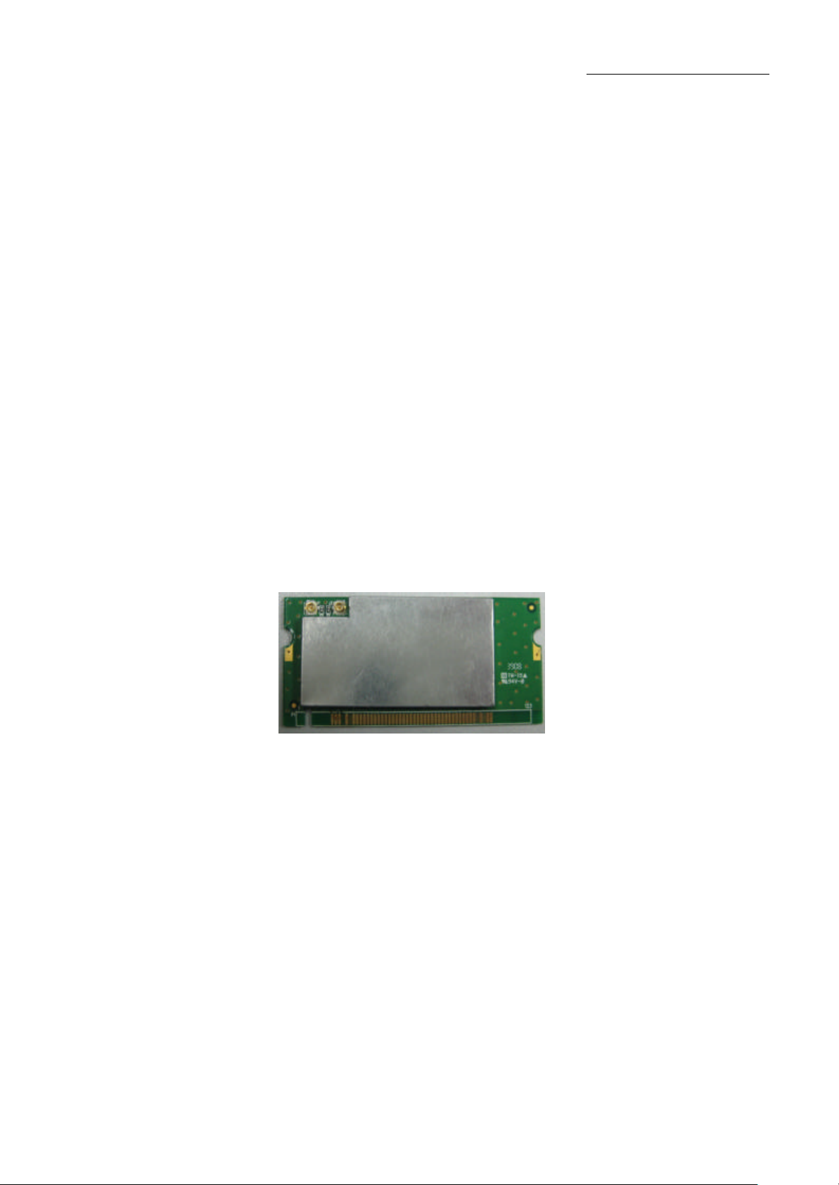
IEEE 802.11b/g MiniPCI WLAN Card
(Model #: WLC-101GA)
Installation Manual
Version 0.1
December 2008
1
Page 2

Preliminary Installation Manual
Table of Contents
Chapter 1 Introduction..................................................................................................................3
Chapter 2 Installation Procedure...................................................................................................4
2.1 Installing the software drivers on MS Windows platform ..............................................4
2.2 Configuration................................................................................................................10
2.3 Current Status................................................................................................................11
2.4 Profile Management ......................................................................................................12
2.5 Diagnostics....................................................................................................................17
2.6 Wireless LAN Installation Guidelines and Authorization for Use ................................19
Chapter 3 Regulatory Information..............................................................................................21
3.1 FCC Information to User ..............................................................................................21
3.2 FCC Guidelines for Human Exposure ..........................................................................21
3.3 FCC Electronic Emission Notices ................................................................................21
3.4 FCC Radio Frequency Interference Statement .............................................................22
3.5 OEM installation Guide ................................................................................................23
Chapter 4 Technical Specifications .............................................................................................25
2
Page 3
Preliminary Installation Manual
Chapter 1 Introduction
The CNE 802.11g WLAN NIC is a complete wireless high speed Network Interface Card
(NIC). It conforms to the IEEE 802.11g protocol and operates in the 2.45GHz ISM frequency
bands.
It provides a complete reference design evaluation platform of hardware and software to
system providers or integrators requiring wireless data communications capability and is ideal
for integration into computer platforms.
Ÿ Fully compliant with the IEEE 802.11g WLAN standards
Ÿ FCC Certified Under Part 15 to Operate in the 2.45 GHz Bands
Ÿ Support for 54, 48, 36, 24, 18, 12, 9, and 6 Mbps OFDM, 11 and 5.5 Mbps CCK and
legacy 2 and 1 Mbps data rates
Ÿ Driver Supports Microsoft Windows ® XP and 2000 (SR1)
Model: WLC-101GA
3
Page 4
Preliminary Installation Manual
Chapter 2 Installation Procedure
2.1 Installing the software drivers on MS Windows platform
The driver installation procedure on MS Windows platform is described as follows. Windows
XP is used as the example. It is similar in other Windows platform (e.g. Windows 2000).
1. Make sure that the miniPCI card has been inserted in your machine properly.
2. Copy the driver into the notebook, execute the Setup.exe.
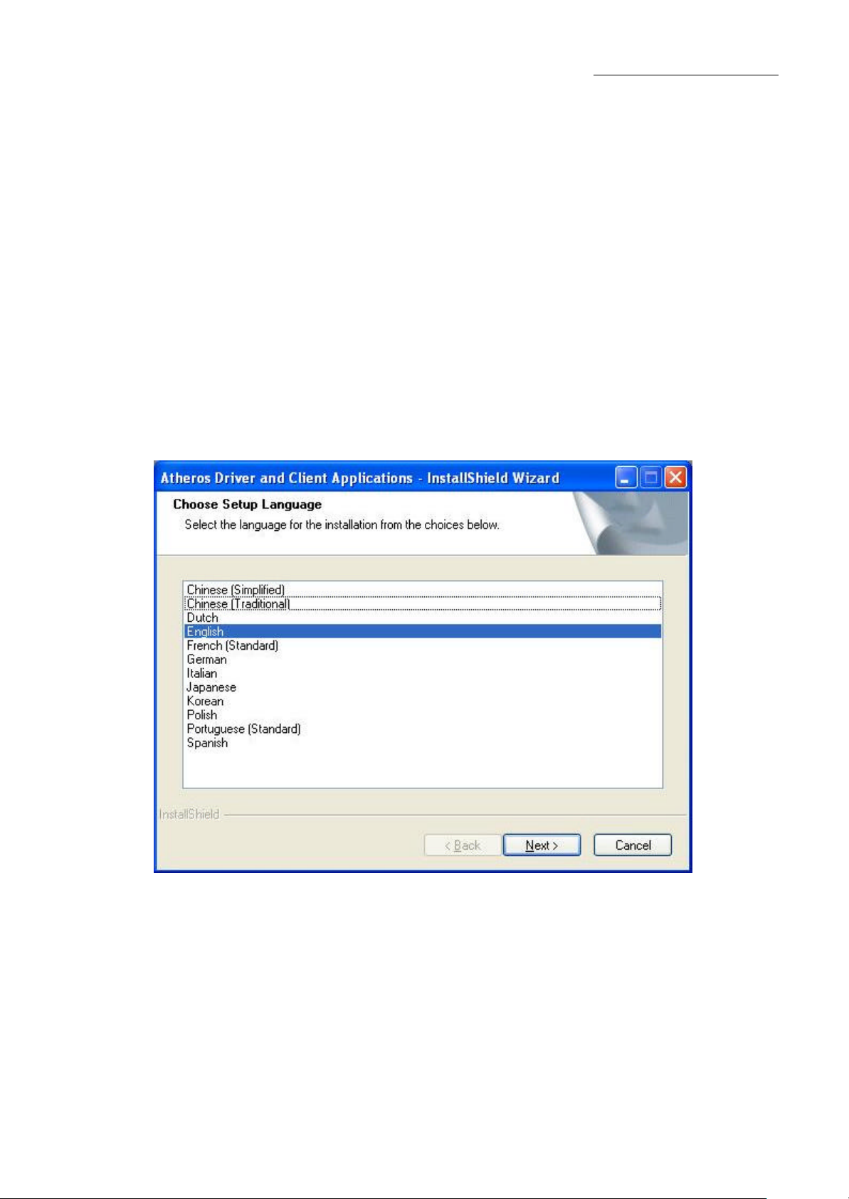
3. Select the language to want to install, Click Next to continue..
Figure 2-1 Choose Setup Language
4
Page 5
Preliminary Installation Manual
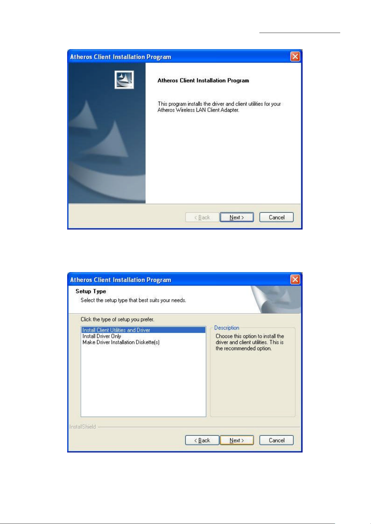
4. To continue,click Next on the screen,figure 2-2.Click Cancel to end the lnstallation
Figure 2-2 Atheros Client Ins tallation Program
5. The Setup Wizard will ask you to choose a Setup type in figure 2-3.lt is recommended that
you select “Install Client Utilities and Driver”.
Figure 2-3 Select the setup type
5
Page 6
Preliminary Installation Manual
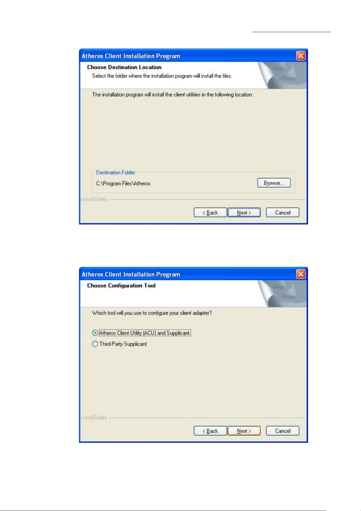
6. Select the folder where the installation progr am will install the files.
Figure 2-4 Choose Destination Location
7. Setup your client adapter. lt is recommended that you select “Atheros Client
Utility(ACU)and Supplicant”.
Figure 2-5 hoose Configuration Tool
6
Page 7
Preliminary Installation Manual
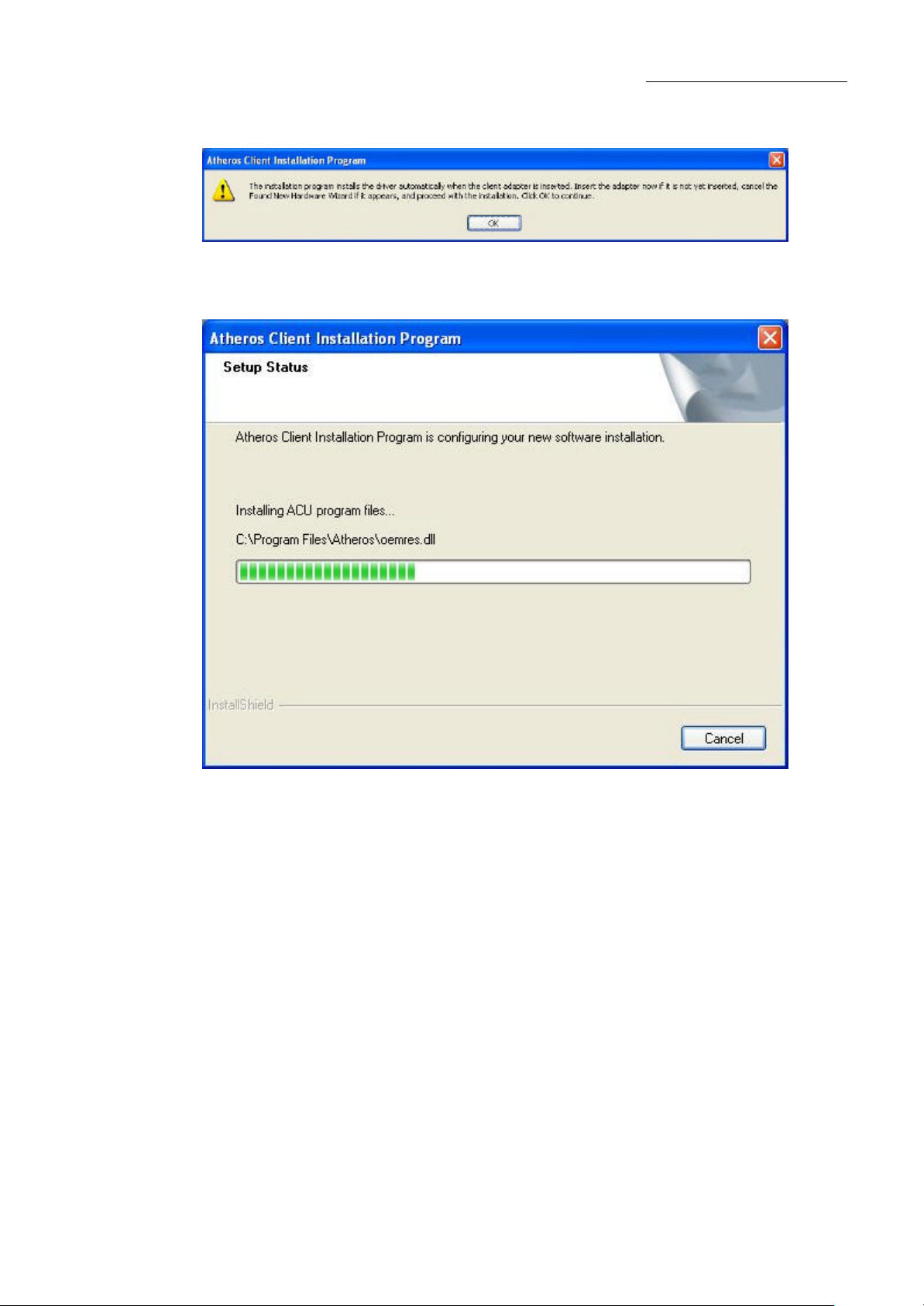
8. The Setup Wizard will notify you of how to proceed with the installation, shown in figure
2-6. Clicd OK to continue the Installation.
Figure 2-6 Information prompt
9. Atheros Client Installation Program is configuring your new software software installation.
Figure 2-7 Setup Status
10. While files are copying .you will see a warning box, shown in figure 2-8a. Please select
YES to continue installation. Our drivers have been tested thoroughly, and are able to work
with the operating system.
7
Page 8
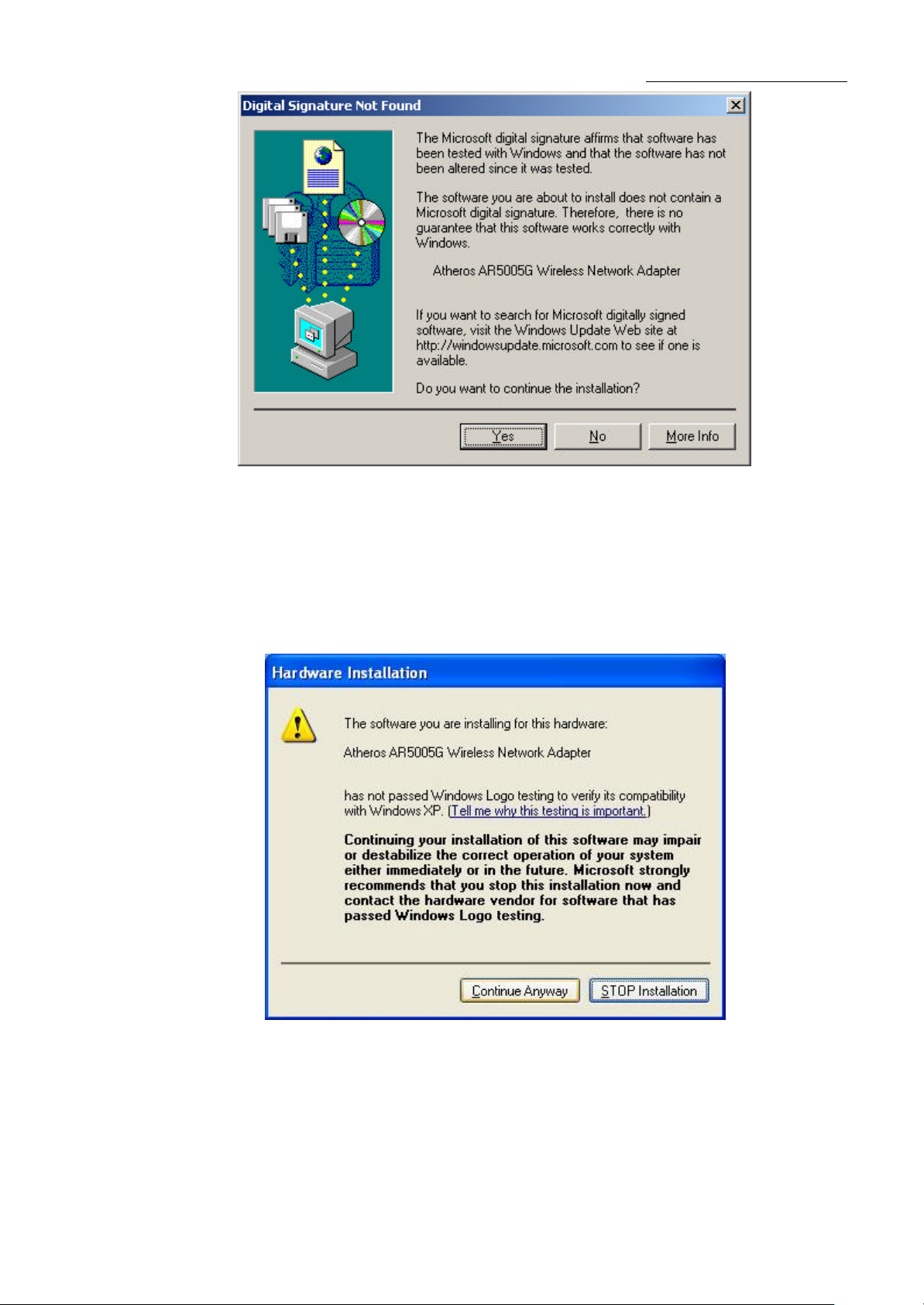
Figure 2-8a Widwods 2000 Warning Box
Preliminary Installation Manual
Note: In Windows XP, the warning box is similar to that shown figure 2-8b. Please select
Continue Anyway to continue installation.
Figure 2-8b Windows XP Warning Box
8
Page 9

Preliminary Installation Manual
11. After the files have been successfully copied, the screen in figure 2-9 will appear Click
Finish to reboot the system.
Figure 2-9 Finish
9
Page 10

Preliminary Installation Manual
2.2 Configuration
The Wireless Adapter can be configured by Wireless Client Utility (WCU). This chapter
describes how to configure your Wireless Adapter for wireless connectivity on your
Wireless Local Area Network (WLAN) and use the data security encryption features.
After Installing the Adapter, the Adapter’s tray icon will appear in your system tray. It
appears at the bottom of the screen, and shows the signal strength using color and the
received signal strength indication (RSSI).
If the icon is gray, there is no connection.
Double-click the icon and the WCU utility will run. You can also run the utility by clicking
the Start>Program>Wireless>Wireless Client Utility. The WCU utility provides a
complete and easy to use set of tools to:
* Display current status information
* Edit and add configuration profiles
* Display current diagnostics information
The section below introduces these above capabilities.
10
Page 11

Preliminary Installation Manual
2.3 Current Status
The Current Status tab contains general information about the program and its operations.
The Current Status tab does not require any configurations.
Figure 3-1 Current Status
The following table describes the items found on the Current Status screen.
* Profile Name - The name of current selected configuration profile. Set up the
configuration name on the General tab of Profile Management.
* Link Status - Shows whether the station is associated to the wireless network.
* Wireless Mode - Displays the wireless mode. Configure the wireless mode on the
Advanced tab of Profile Management.
* Network Type - The type of network and the station currently connected. The options
include:
?Infrastructure (access point)
?Ad Hoc
Configure the network type on the Advanced tab of Profile Management.
* IP Address - Displays the computer’s IP address.
* Data Encryption - Displays the encryption type the driver is using. Configure the
encryption type on the Security tab of Profile Management.
* Server Based Authentication - Shows whether server based authentication is used.
* Signal Strength - Shows the strength of the signal.
11
Page 12

Preliminary Installation Manual
2.4 Profile Management
Click the Profile Management tab of the WCU Utility and the Profile Management screen
will appear, figure 3-3. The Profile Management screen provides tools to:
* Add a profile
* Edit a profile
* Remove a profile
* Switch to another Profile
* Import a Profile
* Export a Profile
* Scan Available Networks
* Order profiles
Figure 3-2 Profile Management tab
2.4.1 Add or Modify a Configuration Profile
To add a new configuration profile, click New on the Profile Management tab. To modify a
configuration profile, select the configuration from the Profile list and click Modify.
The Profile Management dialog box will display a screen similar to that shown in Figure
3-4.
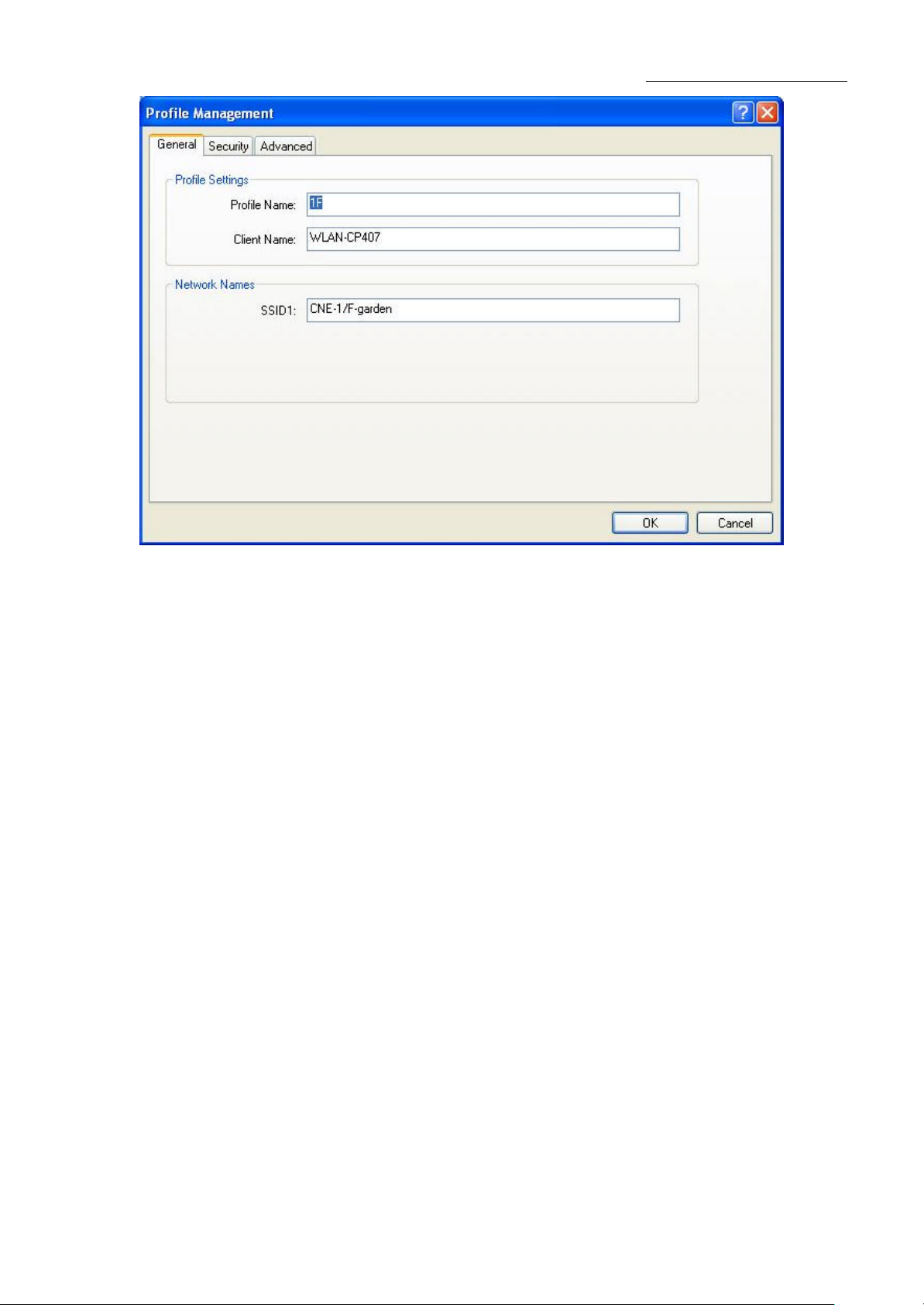
1. Edit the General tab
* Profile Name - Identifies the configuration profile. This name must be unique. Profile
names are not case-sensitive.
* Client Name - Identifies the client machine.
* Network Names (SSIDs) - The IEEE 802.11 wireless network name. This field has a
maximum limit of 32 characters.
12
Page 13
Preliminary Installation Manual
Figure 3-3 General Tab of Profile Management
2. Edit the Security tab
Edit the fields in the Security tab of Profile Management to configure the profile. To define
the security mode, select the radio button of the desired security mode.
* WPA - Wi-Fi Protected Access
* WPA Passphrase - Wi-Fi Protected Access Passphrase
* 802.1x - Enables 802.1x security.
* Shared Key (Static WEP) - Enables the use of shared keys that are defined on both
the access point and the station. To define shared encryption keys, choose the
Shared Key radio button and click Configure to fill in the Define Shared Keys
window.
None: No security (not recommended).
Note: If the access point that the wireless adapter is associating to has WEP set to
Optional and the client has WEP enabled, make sure that Allow Association to Mixed
Cells is checked on the Security Tab to allow association. To complete WEP encryption
configuration, you must select the 802.11 Authentication Mode as appropriate on the
Advanced tab of this Profile Management dialog.
13
Page 14

Preliminary Installation Manual
Figure 3-4 Security tab of Profile Management
Figure 3-5 Define Shared Keys
14
Page 15

Preliminary Installation Manual
3. Edit the Advanced tab
* Power Save Mode -
?Maximum - Selects maximum mode to let the access point buffer incoming
messages for the wireless adapter. The adapter will detect the access point if
any messages are waiting periodically.
?Normal - In Normal mode, the adapter will be switched to maximum mode
automatically when no large packets are retrieved.
?Off - turns power saving off, thus powering up the wireless adapter continuously
for a short message response time.
* 802.11b Preamble - Specifies the preamble setting in 802.11b. The default setting is
Short & Long (access point mode), which allows both short and long headers in the
802.11b frames. The adapter can only use short radio headers if the access point
supports and uses them. Set to Long Only to override allowing short frames.
* Wireless Mode - Specifies 2.4 GHz 54 Mbps, 2.4 GHz 11 Mbps operation in an
access point network. The wireless adapter must match the wireless mode of the
access point with which it associates
* Wireless Mode when Starting an Ad Hoc Network - Specifies 2.4 GHz 54/11Mbps
to start an Ad Hoc network if no matching network name is found after scanning all
available modes.
* 802.11 Authentication Mode - Select which mode the wireless adapter uses to
authenticate to an access point:
?Automatic causes the adapter to attempt authentication using shared, but switches it to open
authentication if shared fails.
?Open System enables an adapter to attempt authentication regardless of its WEP settings. It
will only associate with the access point if the WEP keys on both the adapter and the access
point match.
?Shared-key only allows the adapter to associate with access points that have the same WEP
key.
For infrastructure (access point) networks, click Preferred APs… to specify up to four
access points to the client adapter that attempts to be associated to the access points.
2.4.2 Scan Available Networks
1. Click Scan on the Profile Management, the Available Infrastructure and Ad Hoc
Networks window will appear.
15
Page 16

Preliminary Installation Manual
2. Click Refresh to refresh the list at any time.
3. Highlight a network name and click Activate to connect an available network. If no
configuration profile exists for that network, the Profile Management window will open
the General tab. Fill in the Profile name and click OK to create the configuration
profile for that network.
Figure 3- 6 Scan Available Networks Dialog
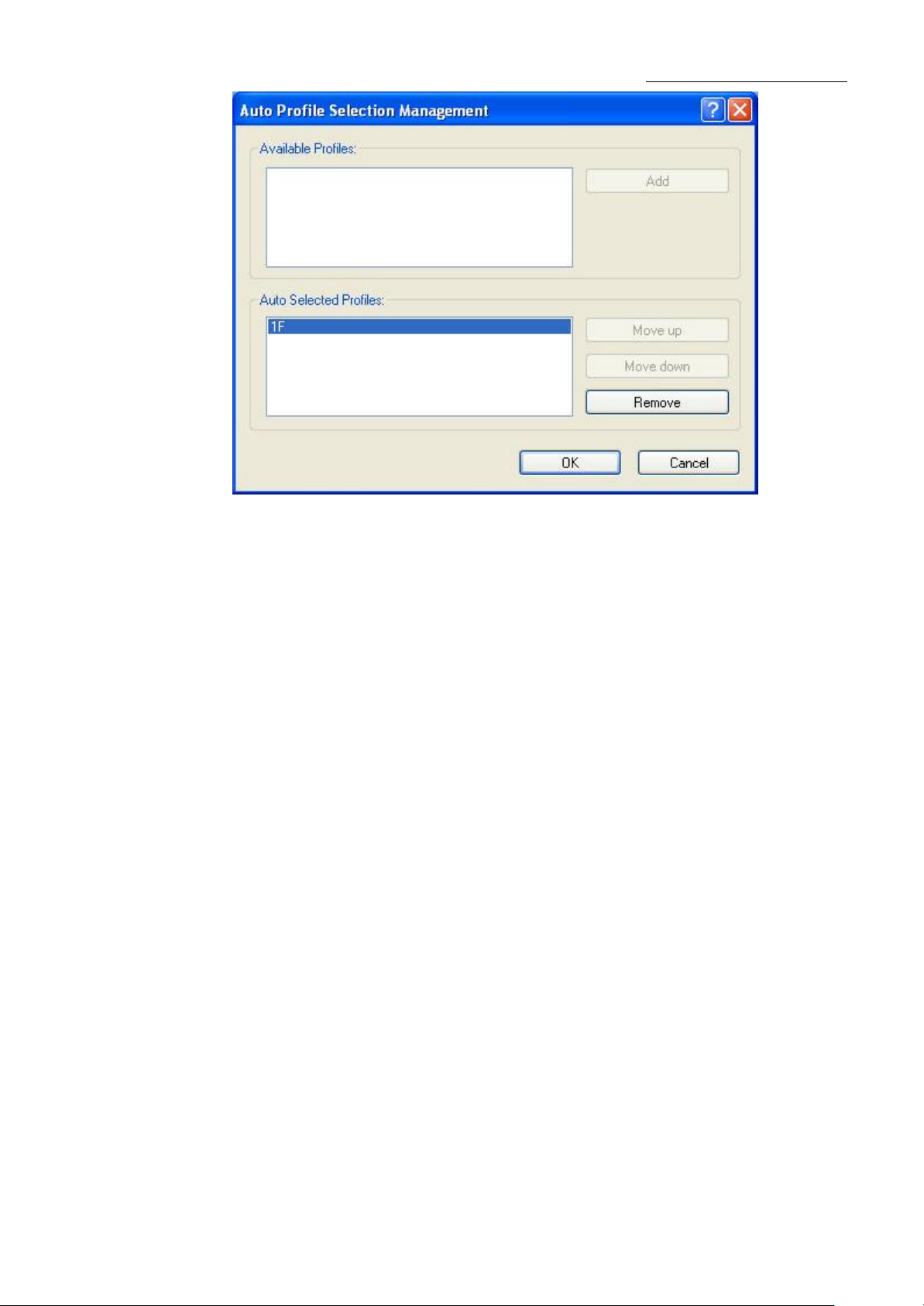
2.4.3 Auto Profile Selection Management
The auto selection feature allows the wireless adapter to automatically select a profile
from the list of profiles and use it to connect to the network. To add a new profile into the
Auto Selected Profiles list, please follow these steps.
1. On the Profile Management tab, click Order Profiles….
2. The Auto Profiles Selection management window will appear, with a list of all created
profiles in the Available Profiles box.
3. Highlight the profiles to add to auto profile selection, and click Add. The profile will
appear in the Auto Selected Profiles box.
4. Highlight a profile in the Auto Selected Profiles box.
5. Click Move Up or Move Down as appropriate. Note: The first profile in the Auto
Selected Profiles box has highest priority, and the last profile has lowest priority.
6. Click OK.
7. Check the Auto Select Profiles checkbox on the Profile Management tab.
Note: When auto profile selection is enabled by checking Auto Select Profiles on the
Profile Management tab, the client adapter will scan for an available network. The profile
with the highest priority and the same SSID as one of the found networks will be used to
connect to the network. If the connection fails, the client adapter will try the next highest
priority profile that matches the SSID until an available network is found.
16
Page 17
Preliminary Installation Manual
Figure 3-7 Auto Profile Selection Management Dialog
2.5 Diagnostics
The Diagnostics tab of the Wireless Client Utility (WCU) provides buttons used to retrieve
receiving and transmitting statistics. The Diagnostics tab does not require any
configuration.
The Diagnostics tab lists the following receive and transmit diagnostics for frames
received or transmitted by the wireless network adapter:
* Multicast frames transmitted and received
* Broadcast frames transmitted and received
* Unicast frames transmitted and received
* Total bytes transmitted and received
17
Page 18

Figure 3-8 Diagnostics tab
Preliminary Installation Manual
2.5.1 Check Driver Information
The Adapter Information contains general information about the wireless network
adapter and the Network Driver Interface Specification (NDIS) driver. Access the adapter
information from the Diagnostics tab.
* Card Name - The name of the wireless network adapter.
* MAC Address - The MAC address of the wireless network adapter.
* Driver - The driver name and path of the wireless network adapter driver.
* Driver Version - The version of the wireless network adapter driver.
* Driver Date - The creation date of the wireless network adapter driver.
* Client Name - The name of the client computer.
Figure 3-9 Adapter Information
2.5.2 Check Receive and Transmit Statistical Information
The Advanced Statistics show receiving and transmitting statistical information for the
18
Page 19

Preliminary Installation Manual
following receive and transmit diagnostics for frames received by or transmitted to the
wireless network adapter.
Figure 3-10 Advanced Statistics
2.6 Wireless LAN Installation Guidelines and Authorization for Use
Installation and use of this Wireless LAN device must be in strict accordance with the
instructions included in the user documentation provided with the product. Any changes or
modifications made to this device that are not expressly approved by Chung Nam Electronics
(CNE) may void the user’s authority to operate the equipment. CNE is not responsible for any
radio or television interference caused by unauthorized modification of this device, or the
substitution or attachment of connecting cables and equipment other than specified. It is the
responsibility of the user to correct any interference caused by such unauthorized modification,
substitution or attachment. CNE and its authorized resellers or distributors will assume no
liability for any damage or violation of government regulations arising from fa iling to comply
with these guidelines.
The use of Wireless LAN devices may be restricted in some situations or environments for
example:
Ÿ On board airplanes, or
19
Page 20

Preliminary Installation Manual
Ÿ In an explosive environment, or
Ÿ In case the interference risk to other devices or services is perceived or identified as
harmful.
In case the policy regarding the use of Wireless LAN devices in specific organizations or
environments (e.g. airports, hospitals, chemical/oil/gas industrial plants, private buildings etc.)
is not clear, please first verify authorization to use these devices prior to operating the
equipment.
20
Page 21

Preliminary Installation Manual
Chapter 3 Regulatory Information
3.1 FCC Information to User
FCC Caution: Any changes or modifications not expressly approved by the party responsible for
compliance could void the user's authority to operate this equipment.
3.2 FCC Guidelines for Human Exposure
Warning:
The antenna(s) used for this transmitter must be installed to provide a separation distance of at
least 20 cm from all persons and must not be co-located or operating in conjunction with any
other antenna or transmitter.
3.3 FCC Electronic Emission Notices
This device complies with part 15 of the FCC Rules.
Operation is subject to the following two conditions:
1. This device may not cause harmful interference
2. This device must accept any interference received, including interference that may cause
undesired operation.
21
Page 22

Preliminary Installation Manual
3.4 FCC Radio Frequency Interference Statement
This equipment has been tested and found to comply with the limits for a class B digital device,
pursuant to Part 15 of the FCC Rules. These limits are designed to provide reasonable
protection against harmful interference when the equipment is operated in a commercial
environment. This equipment generates, uses and can radiate radio frequency energy and, if not
installed and used in accordance with the instructions, may cause harmful interference to radio
communications. Operation of this equipment in a residential area may cause harmful
interferences, in which case the user will be required to correct the interference at his own
expense.
If this equipment does cause harmful interference to radio or television reception, which can be
determined by turning the equipment off and on, the user is encouraged to try to correct the
interference by one or more of the following measures:
Ÿ Reorient or relocate the receiving antenna
Ÿ Increase the separation between the equipment and receiver
Ÿ Connect the equipment into an outlet on a circuit different from that to which the receiver
is connected
Ÿ Consult the dealer or an experienced radio/TV technician for help
22
Page 23

3.5 OEM installation Guide
“Contains TX FCC ID : Q72WLC101GA
Preliminary Installation Manual
23
Page 24

Preliminary Installation Manual
This device is certified as modular radio form with the antenna the gain must be less than 1.8
dBi. Change to other type requires re-evaluation/ certification
24
Page 25

Preliminary Installation Manual
Indoor up to 100m, outdoor up to 250m (Standard transmission
(Adopt 2x to 3x
echnology, it is limited
Typically 685mA in full Transmit (TX), 515mA in full Receive
Chapter 4 Technical Specifications
Appendix A: Specifications
Normal
Interface Mini-PCI interface
Standards IEEE802.11b; IEEE802.11g
Operating System Windows 98; Windows Me; Windows 2000; Windows XP
Transmission
Distance
Radio Data Rate 54/48/36/24/18/12/9/6/11/5.5/2/1Mbps (Auto Rate Sensing)
Sensitivity
Modulation
Media Access
Protocol
Data Security WPA; 64/128/152-bit WEP; TKIP/AES
Frequency 2.412  ̄ 2.462GHz
Spread Spectrum Direct Sequence Spread Spectrum (DSSS)
Channel
Power
distance, It is limited to the environment).
Indoor up to 200m, Outdoor up to 830m
eXtended RangeTM WLAN transmission t
to the environment)
54M: -68dBm/8%PER (TYPICAL)
11M: -84dBm/8%PER
1M, 2M BPSK; 5.5M, 11M CCK; 6M, 9M, 12M, 18M QPSK
24M, 36M 16QAM; 48M, 54M 64QAM.
CSMA/CA with ACK
Consumption
Environmental and Physical
Operating Temp 0℃~40℃ (32℉~104℉)
Storage Temp –40℃ ~ 70℃ (-40℉~158℉)
Humidity
Dimensions
(W×D×H)
(RX)
10% ~ 95% RH, Non-condensing
60×30×3.5 mm
25
 Loading...