

Page 1
Printed in Hong Kong
PA: OI-G5-EN-1309-V2.2-UK
Page 2

GSM/SMS/RFID
Security Alarm System
Features
ARM + Auror CPU
Support 10 remote controls, 50 wireless sensors
and 50 RFID tags
Built-in 1,000,000 RF codes combination
maintains high reliability
Cellular communicator, simple operation
Store 5 phone numbers, 1 speed-dial number,
and 1 RFID SMS notification number
Exit and entr y delay
SMS alert for low battery of two-way accessories
Arm and disarm the system by SMS or free phone call
Remote monitoring site via phone
Firewall to prevent operation from unauthorized users
Built-in loud speaker for siren and two-way talking
Built-in two pieces of 800mAh lithium batteries
enable 5-hour standby
SMS alerts for power failure, power recover y
and low battery
850/900/1800/1900MHz GSM frequency,
applicable for universal
Page 3

Inclu ded Accessories
Control Panel Layout
Record/Play Voice M emo
RFID Tag
Speed D ial
Phone C all
Recording Alarm Message
Elect ronic Loc k Output
SMS Ope ration
Table of Contents
Disa rm
Arm
Sta y Ar m (Home M od e)
Two-Wa y Talk
Call -B ack to Rec ord Voice Me mo
Sett in gs Inqu ir y
Sto re A la rm Phon e No .
Sto re A la rm SMS No .
Sto re S MS N o. for RF ID Tag s
Sto re S pe ed Dial P ho ne Numb er
Chan ge Z one Nam e
SMS Al er t f or L ow Batter y of Ac ce ssori es
1~ 2
3~ 5
6
7
7
8
8
8
9~ 2 9
SMS Al er t f or Tam per Ala rm o f Ac cesso ri es
Chan ge R FID Tags SM S No tice
Entr y and E xit Del ay T ime
Siren Volum e an d Ringi ng Time
Disa rm Passw or d
Sing le Z one Del ay T ime
Chan ge Sys te m Languag e
Dele te W ir el ess Sen sors
Dele te R FI D Tags
Dele te Remot e Co ntrols
Res to re Sys te m to Defaul t Setti ng
Alarm N otification Ways
Phone Remote Control Instruction
Test Mode
Arm & Dis arm by Free Phone Call
Conne ct Wirele ss Accessories & RFID Tags
Conne ct Wirele ss Siren
Speci fications
Wireless Remote Co ntrol
Wireless Door/ Window Contact
Wireless PIR Mot ion De tector
Zone Se tup for Wireless Sensors
30
30
31
31
32
32
33
34 ~ 36
37 ~ 40
41 ~ 49
50
Page 4
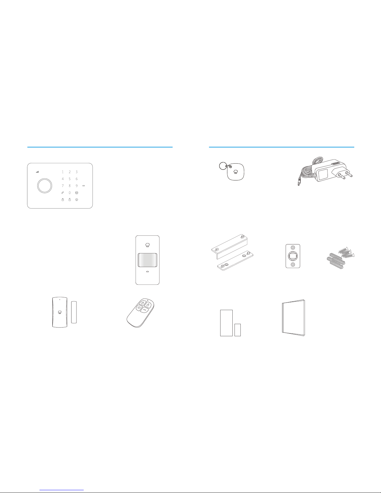
Included Accessories
2
1
The c ontro l panel i s known a s the “he art an d
bra in” for a larm sy stem, w hich is u sed for r ece iving
and p roces sing si gnals f rom wire less se nsors a nd
rem ote con trols. U sers c an ma ke sett ings fr eel y by
GSM c ell pho ne and Ap ps. In ca se of eme rge ncy,
the p anel ri ngs on si te and di als the p re-st ored
ala rm phon e numbe rs auto matic ally. Whe n user s
pic k up the ph one, th ey are ab le to hea r the voi ce
rec ording a lert a nd choo se to mon itor on s ite or
dis arm the s ystem .
*In put key words “ G5” in Go ogle Pl ay or App S tore
to do wnloa d free Ap p for remo te cont rolli ng and
set ting th e alarm s ystem a nytim e and any where .
The wireless PIR Motion Detector is an intelligent passive infrared
motion sensor, designed to detect human movements within an
approximate range of 6 to 8 meters from the detector. The detector
includes fuzzy logic to minimize false alarms from unwanted heat
sources. With power saving feature, the detector will enter sleeping
mode after the second activation within 3 minutes to save power.
CG- G5 C on trol Pa ne l x 1
Wireless PIR Motion Detector x 1
Wireless Remote Control x 2
The remote control is compact and portable; it
is convenient to carry it to arm, disarm, part
arm the alarm system and also make an
emergency call.
Wireless Door/Window Contact x 1
The Door/window contact can be installed on doors,
windows and any other objects that open and close.
The sensor transmits signals to the control panel when
a magnet mounted near the sensor is moved away.
TAG-26 RFID Tag x 2
The RFID tag is for disarming
The system and unlocking the
electronic door lock (if
connected).
Brackets (wall-mounted and
desktop) for control panel x 2
Bracket for PIR Motion
Detector x 1
Double-sided tape for
Door/Window Contact x 1
Screws and wall
plugs x 4
User Manual x 1
AC Adapter x 1
Supply power to the control panel. In case
of power failure, two built-in backup
batteries in the panel will support 5-hour
standby.
Page 5

4
3
Touch Keypad
Status Indic ator
RFID Reader / Play Voic e Memo
Call
Arm
Disarm
Stay Arm (Home Mode)
Record Voice Memo /
Connect Button
GSM Signal Indicator
GSM network searching: Flashes once every second
GSM signal in normal: Flashes once every two seconds
Control Panel Layout
Arm
Press to arm the system.
Home mode
Press to arm the sytem in home mode.
All the sensors in Normal Zone are armed except those in
Home Mode Zone which are disarmed so that user can move
freely at home.
Disarm on keypad:
Input 4 digits password (default:1234) , and press to
disarm the system after one beep.
If three beeps are heard, password is wrong and
please input again.
Disarm by RFID tag:
Induce the RFID tag to the RFID Reader area to
disarm the system.
Page 6
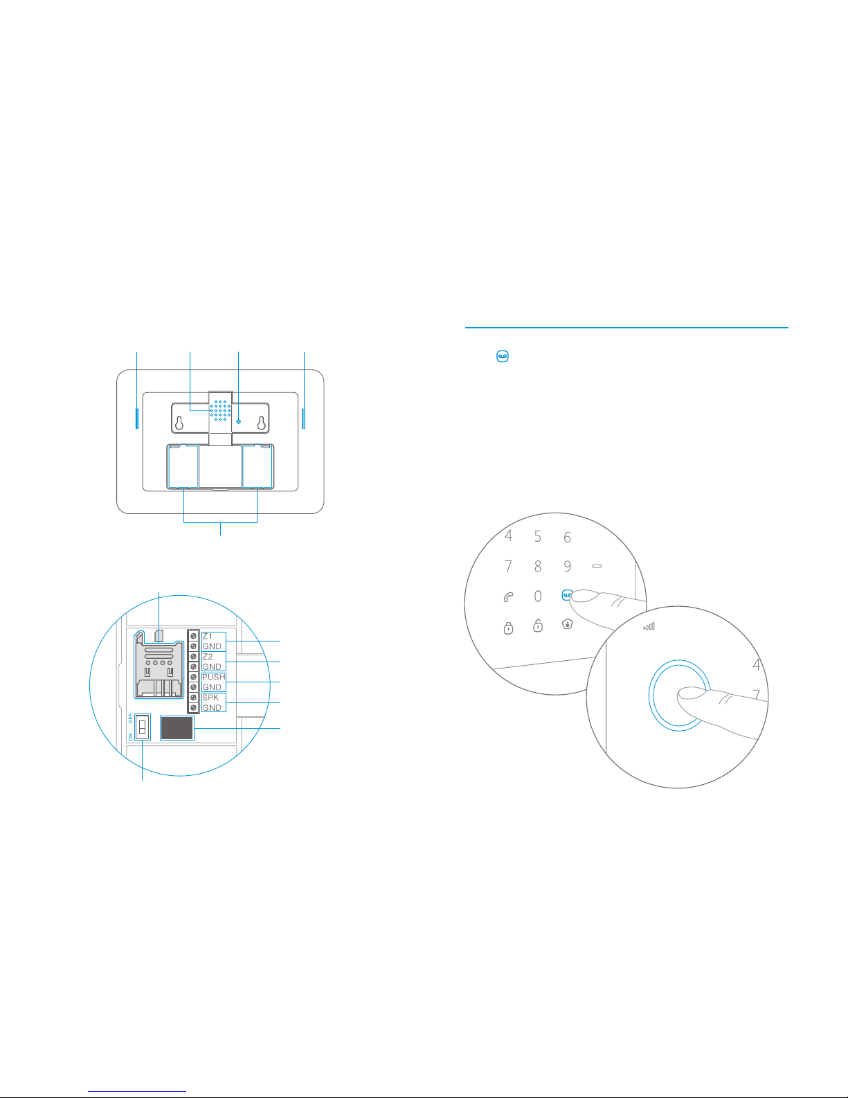
Record / Play Voice Memo
Press for 2 seconds to record 10 seconds voice messages.
Or send SMS to system for calling back to record the voice
messages. The Play Voice Memo Button will be flashing in
green to remind you. Users can touch the center of circle to
listen to the voice memo. The LED indicator blacks out when
the voice memo is played. Replay by touching it again.
MIC
Tamper Switc h Loudsp eaker
Back-u p Batteries
Buzze r
SIM Card S lot
Power On/O ff
Input fo r Wired Sensors
(24-h our zon e)
Outpu t for
Electr onic Lock
Adapte r Interface
Outpu t for Wir ed Sire n
≤ 500mA
Input fo r Wired Sensors
(norm al zone )
Rea r Side
6
5
Page 7

8
7
Speed Dial
Press Call Button , the panel auto dials to pre-stored
phone number of the host, the LED blacks out af ter talk.
User can also press Call Button to end talk.
RFID Tag
The RFID tag is for disarming the system and unlocking
the electronic door lock (if connected).
You can rename the RFID tags and store a mobile phone
number to send SMS notice when family members come
home and disarm the system.
Note!
Only after SMS No. is stored, and the RFID tags SMS notice is changed (4 RFID tags
can be renamed), users ca n receive not ice SM S once s omeo ne dis arms the system
by RFID tag.
Nancy
Admin istrator
Mom
Nancy cam e home
Phone Call
Dial phone number and then press Call Button to start
talk, the LED blacks out after talk .
User can also press Call Button to end talk.
Electronic Lock Output
When system is disarmed, the output signal opens electronic
lock automatically.
Make sure the panel is in home mode. Input passcode, and
then press the button and button on the panel, the LED
light of button is on, the panel starts 10 seconds recording
of the alarm message.
When the alarm message is recorded, user will firstly hear the
alarm message when picking up the phone call from the
panel. Then, user can start remote control the control panel.
See detailed instruction in Page 30.
Recording Alarm Message
Page 8
10
9
???
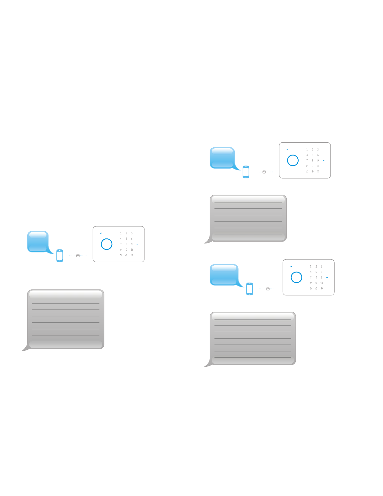
SMS Operation
System replies third grade guide menu:
‘91~99’ Zone name
‘10’ RFID tags SMS notice
‘11’ Entr y and exit delay time
‘12’ Siren volume and ringing time
‘13’ Disarm password
‘14’ Single zone delay time
Send:
??
‘5’ Store alarm phone No.
‘6’ Store alarm SMS No.
‘7’ Store SMS No. for RFID tags
‘8’ Store speed dial phone No.
‘???’ System setups
System replies second grade guide menu:
Send:
?
Insert a SIM card to the control panel, then send a text
of to the SIM card number, the operation guide
message will be replied.
You can control the alarm system by following the
guide message:
“?”
System replies first grade guide menu:
‘0’ Disarm
‘1’ Arm
‘2’ Home mode
‘3’ Two-way talk
‘4’ Call-back voice memo
‘00’ Settings inquiry
‘??’ Store phone and SMS No.
Send:
Page 9

Arm
Stay Arm (Home Mode)
12
11
2
Send:
System in home mode.
1
Send:
System armed.
0
Disarm
Send:
System disarmed.
Page 10
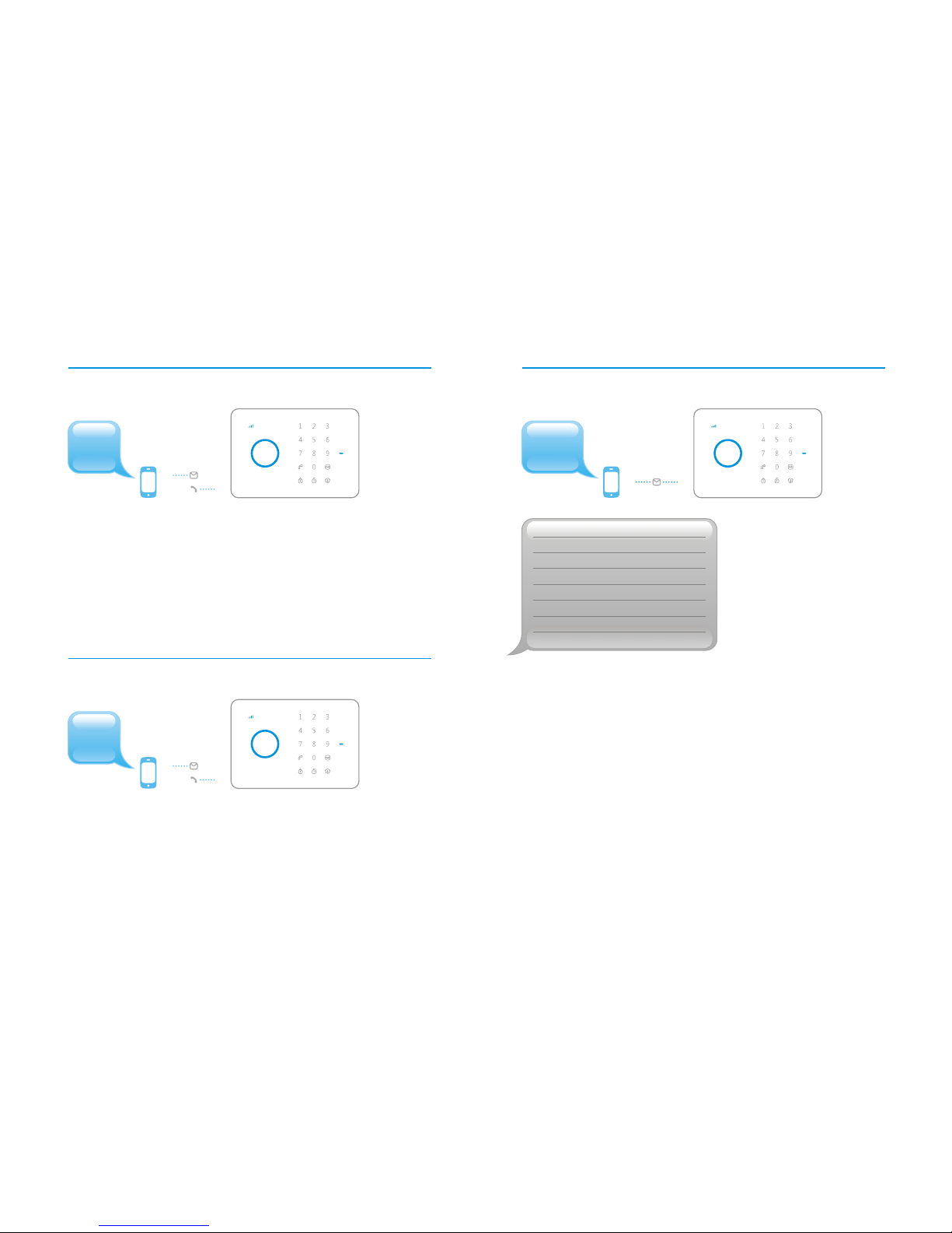
Settings Inquiry
14
13
00
System status
Entr y and exit delay time: 0sec
Single zone delay time: 30sec
Siren volume: 2
Siren ringing time: 5min
Disarm password: 1234
Send:
Note:
Valu e of d ef au lt setting will be changed once u se rs finish pr og ra mm in g.
4
3
Two-Way Talk
Send to the SIM card number, the alarm will call back.
Pick up the phone and star t two-way talk.
‘3’
Call-Back to Record Voice Memo
Send to the SIM card number, the alarm will call back.
Pick up the phone, and leave 10 seconds message.
The panel will hang up after 10 seconds.
‘4’
Send:
Send:
Page 11
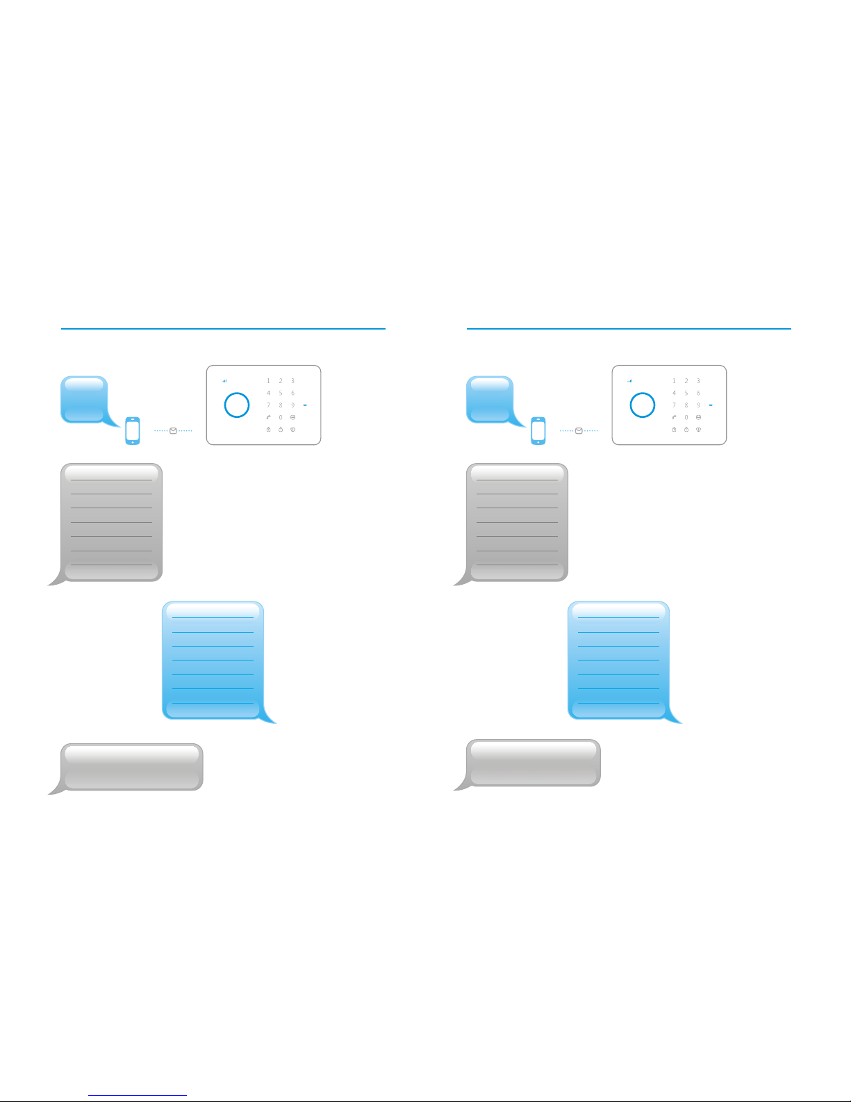
Store Alarm SMS No.
16
15
6
Send:
SMS:
1.
2.
3.
4.
5.
SMS:
1. 67890033
2. 67890022
3. 67890011
4. 67890000
5.
Forward > Ed it
Store alarm SMS No.
successfully.
5
Send:
Store Alarm Phone No.
TEL:
1.
2.
3.
4.
5.
TEL:
1. 67890033
2. 67890022
3. 67890011
4. 67890000
5.
Forward > Ed it
Store alarm phone No.
successfully.
Special T ip s:
Firew al l fe at ure is adopted to pre ve nt n on store d ph on e no . an d SM S no . to remote
contr ol t he s ys te m an d ch an ge s et ti ng s.
Special T ip s:
Please ed it o n th e ba si s of the re pl ie d te xt
and don' t change the fo rm at . Ot he r wi se ,
the syste m wi ll n ot r ec og ni ze t he
command .
Page 12
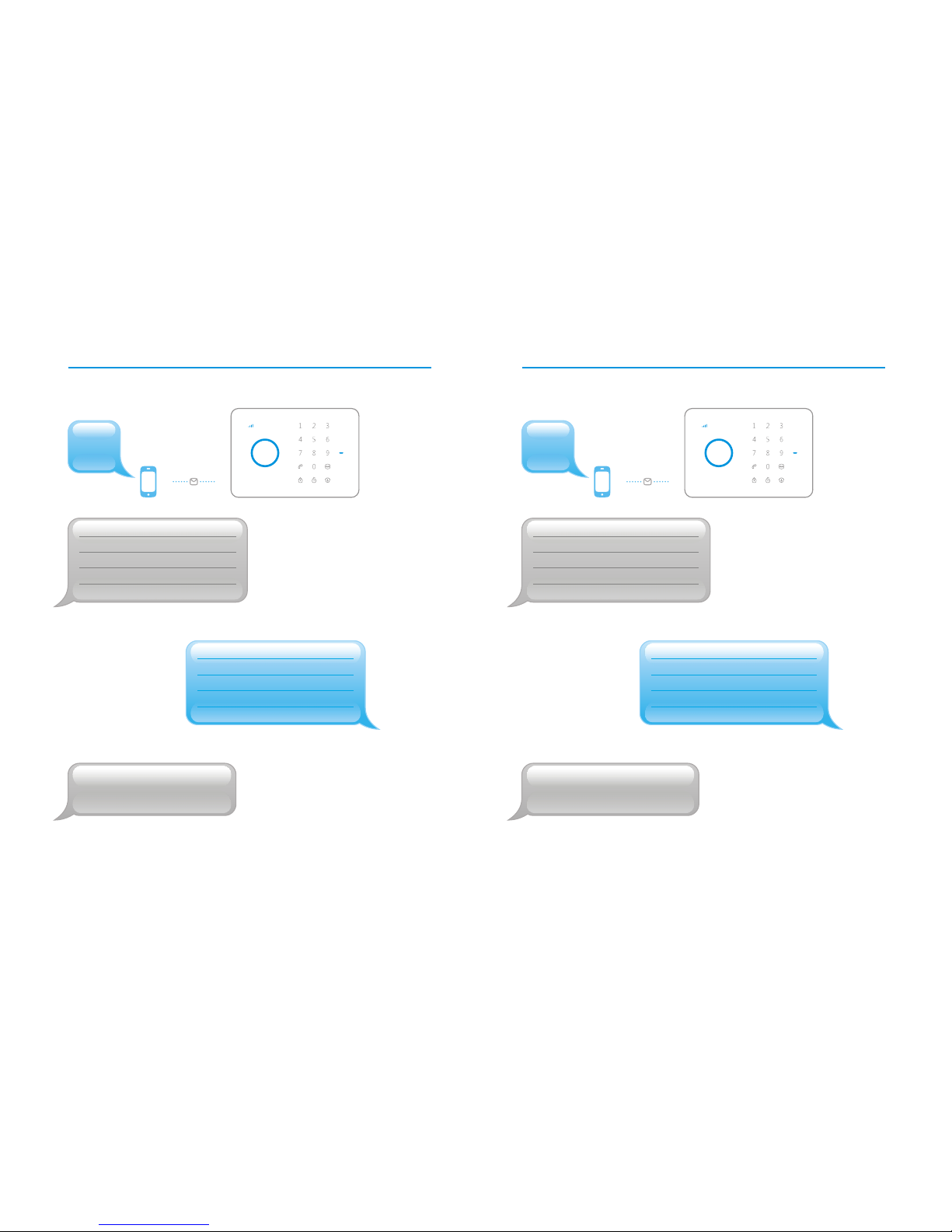
Store Speed Dial Phone Number
18
17
8
Send:
Speed dial phone number
(0-20 digits):
1. 67890033
Forward > Ed it
Store speed dial phone
number successfully.
Speed dial phone number
(0-20 digits):
1.
7
Store SMS No. for RFID Tags
Send:
Forward > Ed it
Store SMS No. for RFID
tags successfully.
SMS No. for RFID tags
(0-20 digits):
1.
SMS No. for RFID tags
(0-20 digits):
1. 67890033
Note: On ly a fte r SM S No. is stored , and the R FI D tags
SMS no ti ce is cha ng ed, use rs can receiv e no tice SM S
once s om eone di sa rms the s ys tem by RFID t ag.
Page 13

91
Change Zone Name
Special Tips!
st th
Users can change the 1 ~ 9 zone names. The zone name should be
30 English characters at most for each line due to SMS character limit.
Other alarm zones are fixed as Zone 10 alarm, Zone 11 alarm and so on.
Send: 91~ 99
Zone1 name: Zone 1 alarm
Zone1 name: Entrance door sensor
Forward > Ed it
SMS Alert for Low Battery of Accessories
(available for two-way accessories such as DWC-102 and PIR-900/910)
SMS will be sent for 1-9 zones with its zone name as
“Zone name + low battery”.
SMS alert for 10~50 zones will be “Zone number + low battery”.
(available for two-way accessories such as DWC-102 and PIR-900/910)
SMS will be sent for 1-9 zones with its zone name as
“Zone name + tamper alarm”.
SMS alert for 10~50 zones will be “Zone number + tamper alarm”.
20
19
Change zone name
successfully.
Bedro om PIR tamper
alarm.
Zone 10 tamper alarm.
Zone 10 low batter y.
Bedro om PIR low batter y.
SMS Alert for Tamper Alarm of Accessories
Page 14
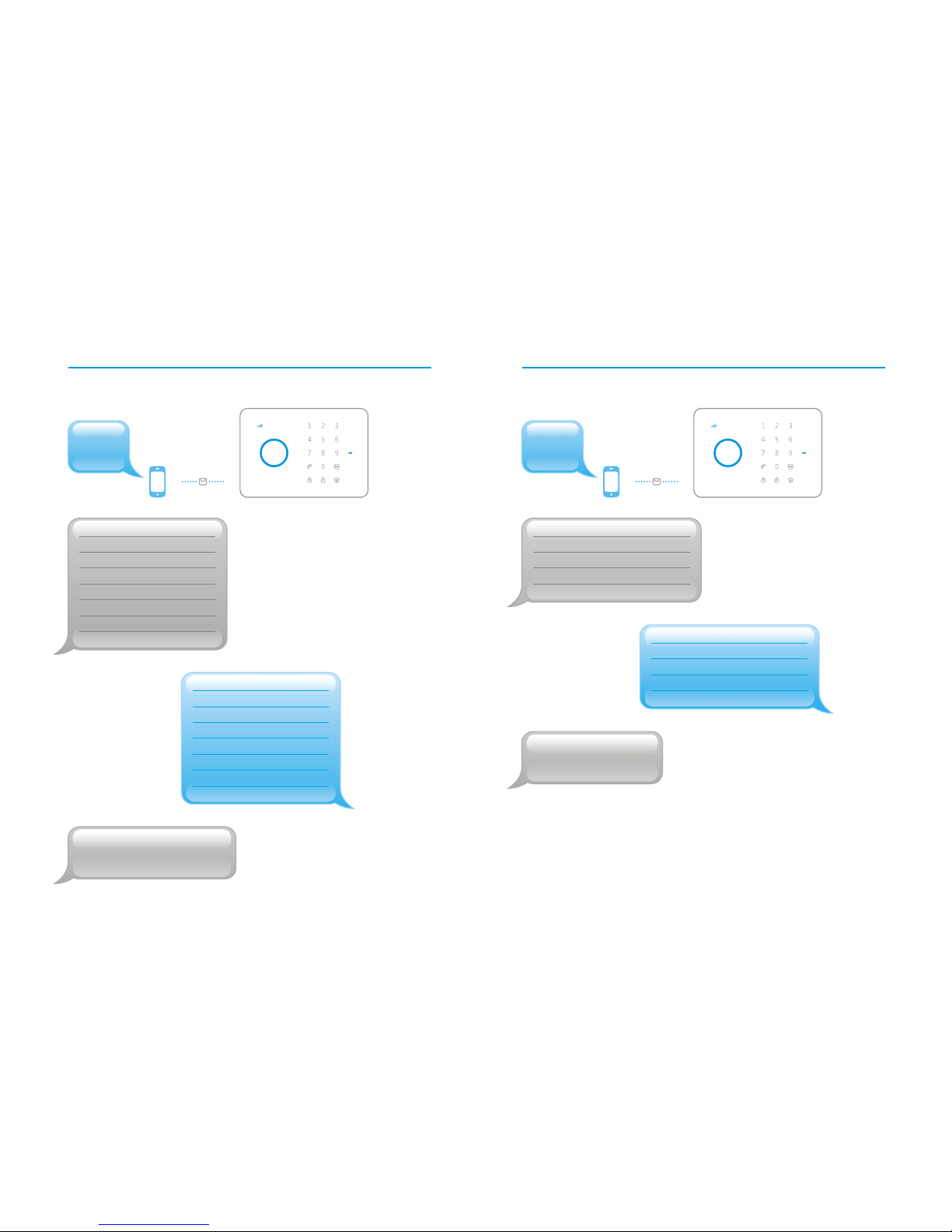
1110
Change RFID Tags SMS Notice Entry and Exit Delay Time
Send: Send:
Change RFID tags SMS
notice:
1.
2.
3.
4.
Change RFID tags SMS
notice:
1. Tom
2. Nurse
3. Nancy
4. David
Forward > Ed it
Entr y and exit delay time
(0-300 sec.):
0
Entr y and exit delay time
(0-300 sec.):
10
Forward > Ed it
Notice!
If users don’t want to take remote control or RFID cards with them, this function
can be used. Once the delay time is set, when you arm the system, one beep will
be heard every second to remind the user to leave.
The reminding rhythm will be speeded up in the last 15 seconds.
Once the intruder is detected, the alarm will be delayed accordingly.
22
21
Set delay time
successfully.
Change RFID tags SMS
notice successfully.
Note:
Only af ter SMS No. is stor ed , an d
the RFID ta gs S MS n ot ic e is
chang ed , us er s ca n re ce iv e no ti ce
SMS once so me on e di sa rm s th e
syste m by R FI D ta g.
Page 15
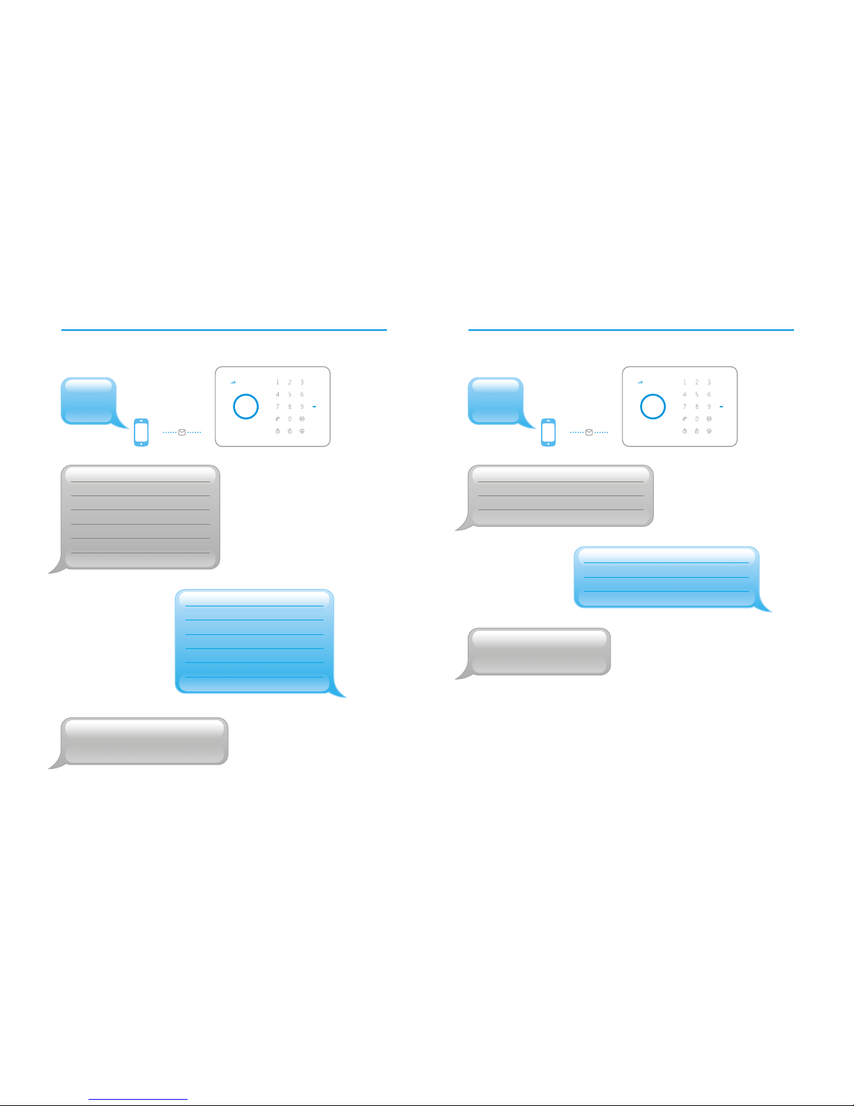
1312
Siren Volume and Ringing Time Disarm Password
Send: Send:
Siren volume(0 Mute,
1 Low, 2 High):
2
Siren ringing time(1-9min):
5
Forward > Ed it
Disarm password(4-6 digits):
1234
Disarm password(4-6 digits):
8888
Forward > Ed it
24
23
Set siren volume and
ringing time successfully.
Set disarm password
successfully.
Siren volume(0 Mute,
1 Low, 2 High):
1
Siren ringing time(1-9min):
3
Page 16

0086
0001
14
Single Zone Delay Time Change System Language
Send: Send: 008 6 to change language to be Ch ine se
Send: 000 1 to change language to be En gli sh
Single zone delay time (0-300 sec.):
30
Single zone delay time (0-300 sec.):
15
Forward > Ed it
26
25
Set single zone delay time
successfully.
Set English successfully.
中文语言修改成功!
Page 17
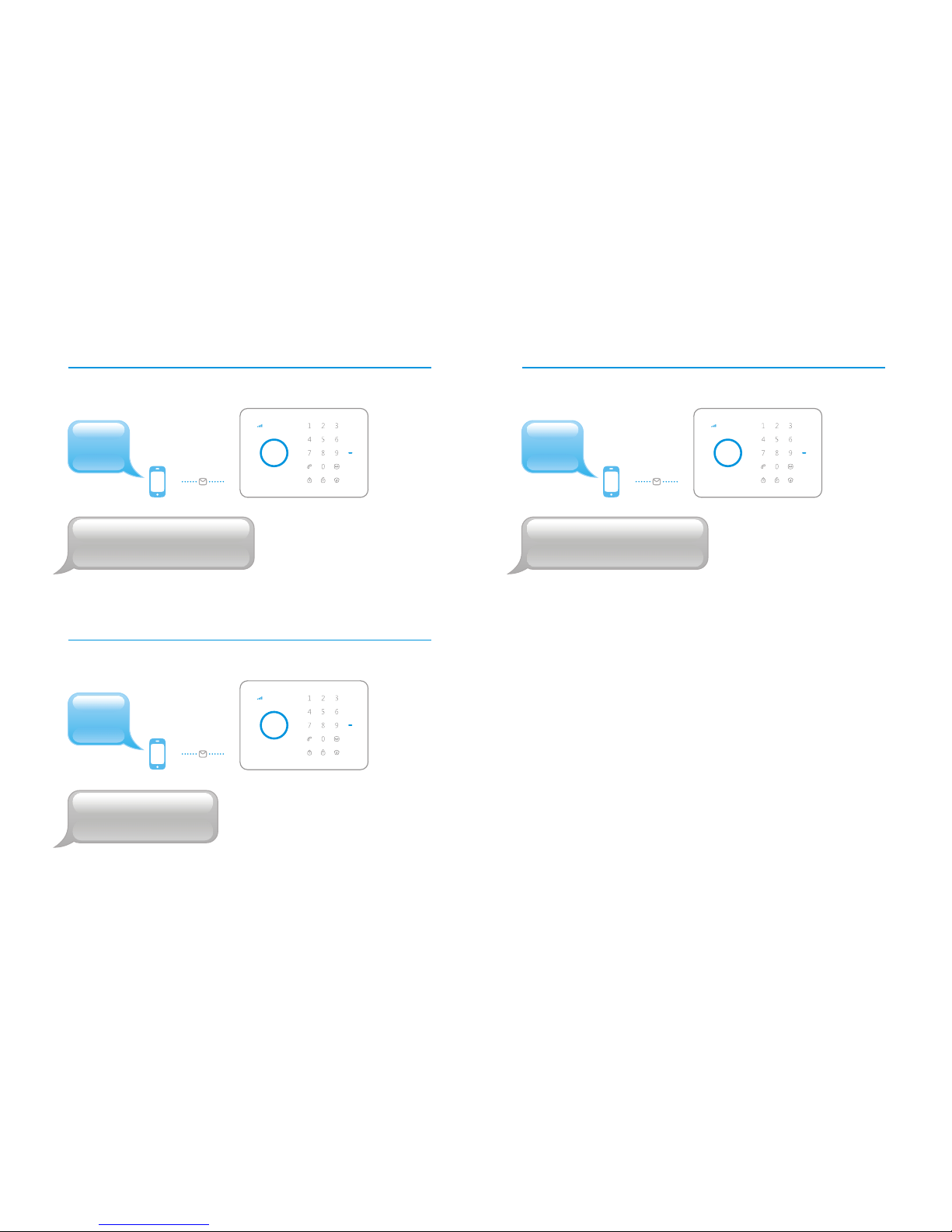
22
Delete Wireless Sensors Delete Remote Controls
Send: Send:
Send:
Delete RFID Tags
28
27
21
Delete wire less sensors
successfully.
Delete RFID tags
successfully.
Note:
Pre ss Tam pe r Sw itch 3 times within 3 seconds, all wi re le ss s en so rs ,
RFID tags , an d re mo te c on trols will be deleted a fter t wo b ee ps .
23
Delete remote controls
successfully.
Page 18
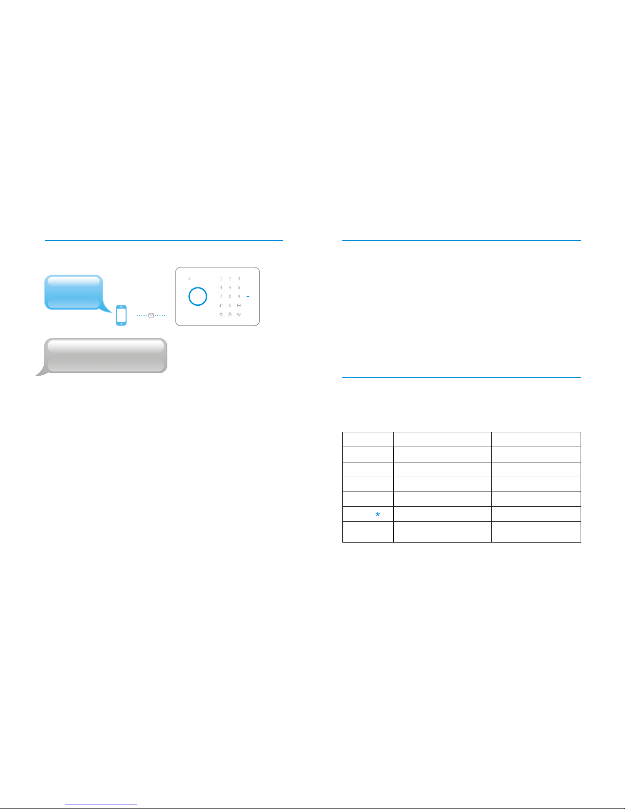
30
29
Once t he al arm s ystem is triggered , the contro l panel will
send SMS in t urn s, an d the n will make ca lls i n turns. The
first rou nd of dia lin g, ea ch stored ph one n umber will get
the ph one c all . From the second round, as long as one user
pick s up th e pho ne, t he co ntrol panel will stop di ali ng to
next numb er.
Alarm Notification Ways
Phone Remote Control Instruction
User can co ntrol the alarm s yst em by p hone only when
receiving an alarm call for an em ergency event .
Operation
Function
Illustration
Press 1
Press 0
Press 9
Press 6
Press
Press #
Arm the system
Disarm the system
Turn on siren
Turn off siren
Two-way talk
Re-play recorded alarm
voice message
Deter the intruder
If it is not heard clearly
0000
Restore System to Default Setting
Send:
System has been restored
to factory settings.
Note:
Af ter pro gr am mi ng , on ly s to red number s can send SMS to res to re t he s ys tem.
Or press Tamp er Switch 5 times within 3 seconds , the
system wi ll be restored to fac tor y s ett ing s after tw o beeps.
Page 19

Connect Wireless Siren
The newly-added wireless siren can be used after connecting to
the control panel.
Press the Connect Button of the wireless siren for 0.5 second,
the Connect Button LED indicator lights on, and then press the
Arm Button on the control panel, the siren will be connected
after one beep is heard.
Testing: Press the Arm Button on the remote control, to make
sure that the internal siren and wireless siren both beep once,
the connection is successful. If not, the connection fails, please
reconnect them.
Once the intruder is detected, both internal siren and wireless
siren will hoot to deter the illegal intruder. (The siren will be
off in 5 minutes as the default setting). At the same time, the
alarm system will send SMS and auto dial to users.
Operation:
Connect Wireless Accessories & RFID Tags
Input 4-6 digits password, press Connect Button , the LED
indicator lights up, then trigger the accessory or RFID tag once
within 15 seconds, the connection is successful after a beep.
Once two beeps are heard, the accessory has been connected
before. The first connected accessory is in Zone 1, the second
one in Zone 2, and so on.
32
31
Arm & Disarm by Free Phone Call
Arm
Call the control panel number, hang up when hearing the ring
tone. The panel will call back. The user hangs up the phone
directly to arm the system.
Disarm
Call the control panel number, hold on until the panel hangs
up the call. The panel will not call back. System is disarmed.
Test Mode
Press the Disarm button on t he panel for 3 time s, th e
system en ters Test Mo de fo r 10 minutes af ter a long beep.
Duri ng th is pe rio d, th e panel w ill n ot al arm b ut gi ve out
three beeps when the tamper swi tch or the sensors
conn ect ed are tr igg ered.
Press the Arm button on t he panel to ex it Test Mode .
Page 20
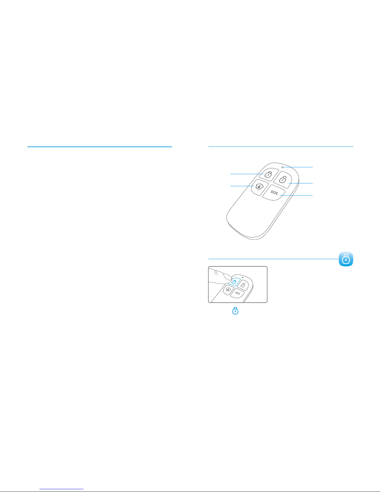
Specifications
GSM/SMS/RFID Security Alarm System
CG-G5
Input: AC 110-240V, 50/60Hz
Output: DC 12V 500mA
850/900/1800/1900MHz
110mA
340mA
Lithium Battery : 3.7V 800mAh x 2 PCS (BL-5B)
95dB
10pcs remote controls, 50pcs wireless sensors
and 50pcs RFID tags.
315MHz or 433MHz (±75KHz)
ABS plastic
Temperature: -10ºC~55 ºC
Humidity: ≤ 80% RH (non-condensing)
Panel : 188×132×26mm
Product name :
Model No. :
Control panel’s power supply :
GSM working frequency :
Standby current :
Alarm current :
Internal battery backup :
Internal siren :
Allowed amount of expandable wireless accessories :
Radio frequency :
Housing material :
Operation condition:
Size (L x W x H) :
34
33
Wireless Remote Control
LED Indicator
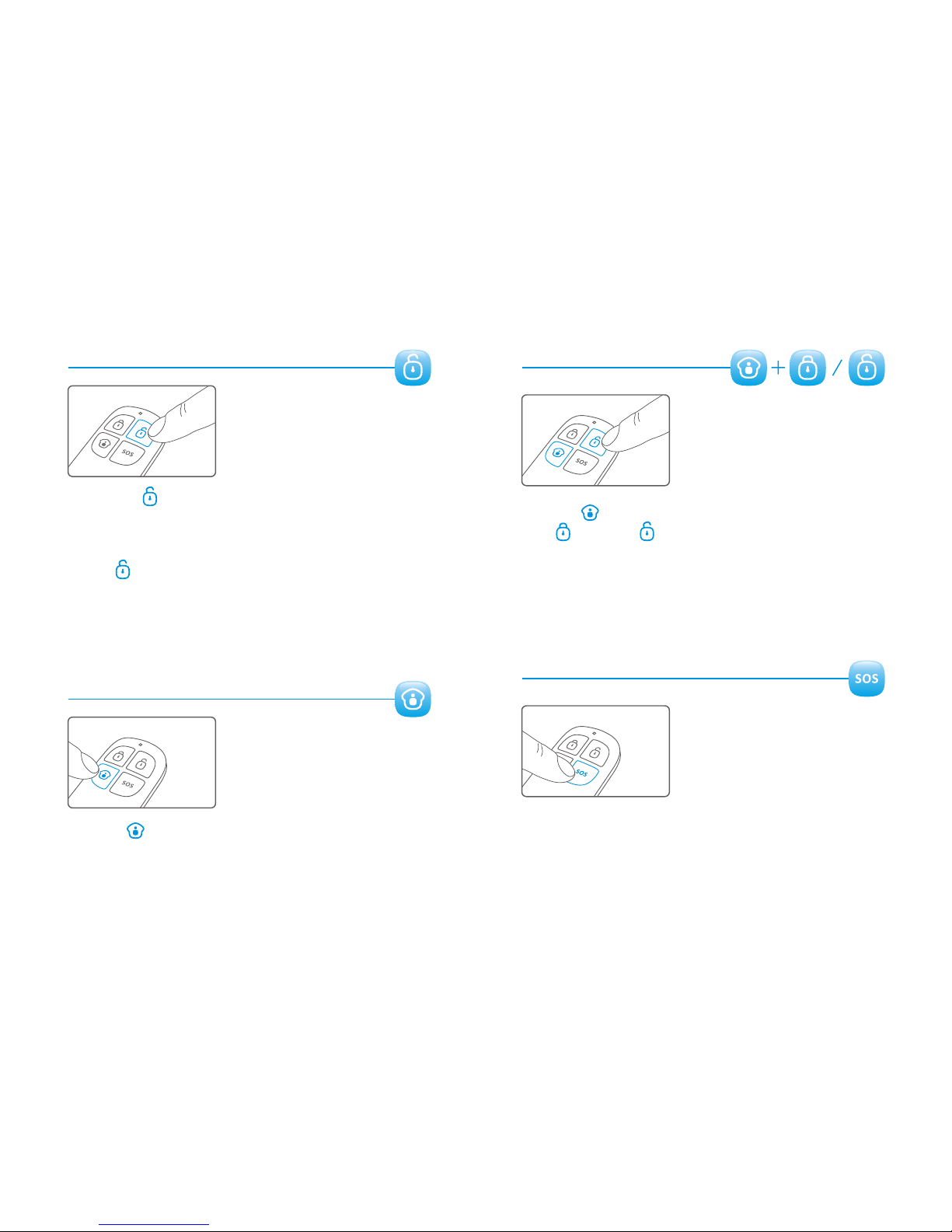
Disarm
Arm
Stay
Panic
Arm
Press to arm the alarm panel and the LED indicator
lights on (siren hoots once), the system enters Arm state.
{Arm }
If there comes an intruder, the siren will hoot to deter the intruder.
(The siren turns off after ringing for 5 minutes as default setting.)
At the same time, the system dials the pre-stored phone numbers
automatically.
Page 21
Disarm
Home Mode
Press to disarm the alarm panel and the LED indicator
blacks out (siren hoots twice), the system is disarmed.
{Disarm }
When intruders are detected, siren will keep hooting. Press
to stop siren hooting.{Disarm }
Press button on the remote control, the system state
LED is on. All the sensors in Normal Zone are armed except the
motion detector in Home Mode Zone which is disarmed so that
user can move freely at home.
{Stay }
36
35
Mute Mode
Press button on the remote control, then press
or button, the siren keeps silent to finish
the operation. The system is armed or disarmed in mute without
disturbing other people.
{Stay }
{Arm } {Disarm }
Emergency Call
No matter what state the control panel is in, once SOS button on
the remote control is pressed, the system immediately goes into
emergent alarming state.
Page 22
38
37
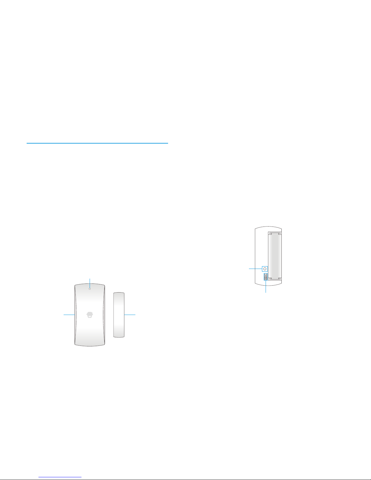
Appearance
Wireless Door/Window Contact
Features
LED i ndicato r
Transmitter
Mag net
The DWC- 102 is a Door/Wi nd ow Contact (Two-wa y) tha t can be
ins talled on door s, windows, and any other objects tha t op en and
close. The sensor transmits sign als to the con trol panel when a
mag net mou nt ed near the sens or is mov ed away. It will also
transmit aler t sign al to the contro l pa ne l in case of low ba ttery.
External inp ut for wired accessor y is available at the N/ C inter face.
The tamper protection ensures tha t sabo tage attempt s to mov e the
con tact wi ll resul t in an alarm activation .
LED Indication
AA 1.5 V LR 6
Tampe r switch
Zon e setting
PCB Layout
LED flashe s on ce:
Flash once per 3 secon ds :
Door/window is opene d and
transmitter send s sign al to the contro l pa ne l.
Low powe r indication , pl ease cha ng e
batter y as soo n as possibl e.(User wi ll get aler t SMS about the low
batter y if the door contact is con ne cted to the GS M alarm system. )
Page 23
40
39
Installation & Notice
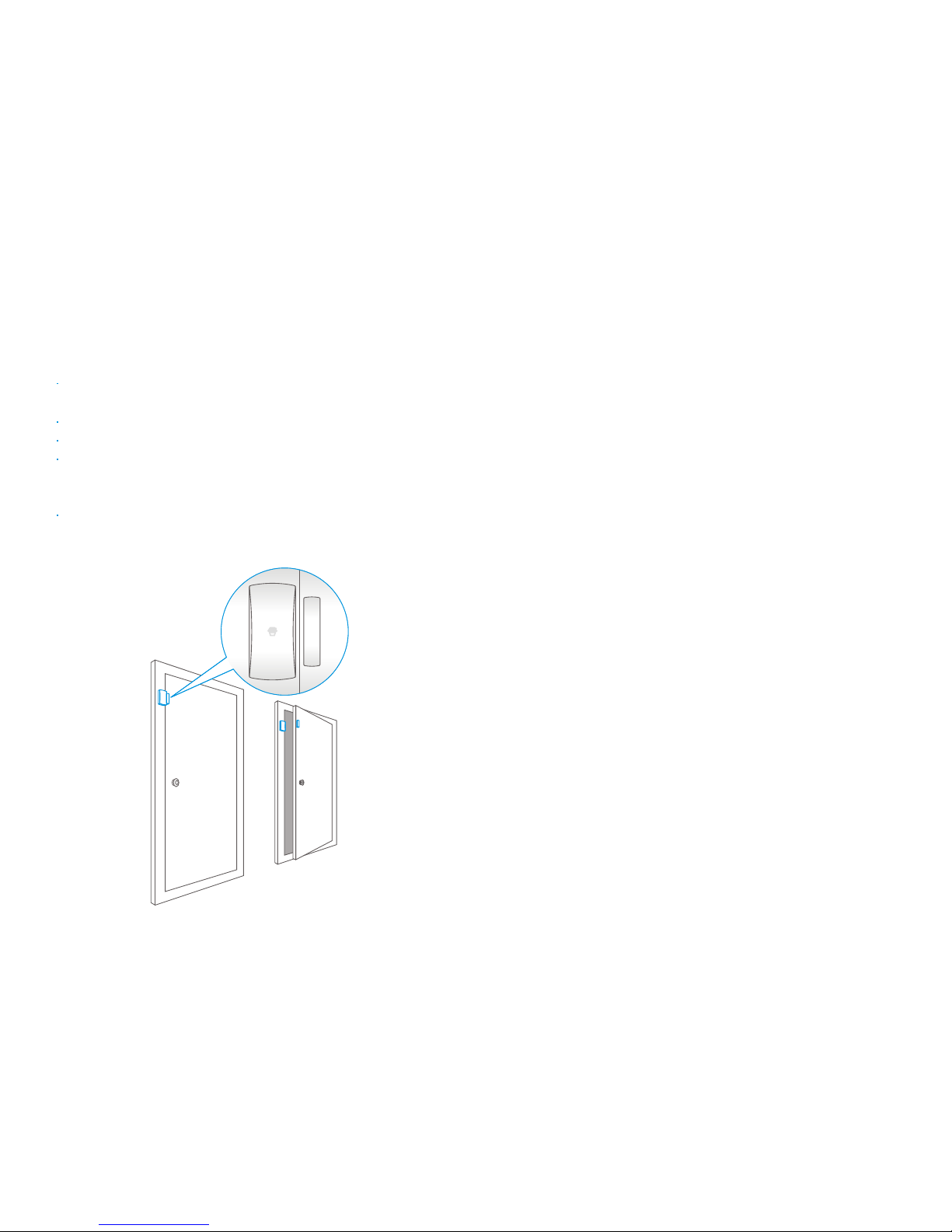
Remove the batter y activation strip,the sensor wi ll ent er
working state immed iately.
Mou nt the sens or on the do or frame and the mag ne t on the door.
Mak e sur e the mag net is on the right side of the transmitter
Place the transmitter in the desired loc ation, mou nt the mag net
no more than 1cm awa y from the transmitter and secure the
transmitter and mag net with do ub le-sided tape s or screws.
Avoi d mou nting sens or s in are as with a large quant ity of met al
or electrical wi ring , such as a furnace or utility room.
Specifications
Power sup pl y
Static cur rent
Alarm current
Transmitting distanc e
Radio frequenc y
Housing mat erial
Operation condition:
Transmitter di men sions (LxWxH)
Magnet dimen sion s (LxWxH)
DC 1.5V (AA 1.5V LR6 Batter y x 1pc)
≤ 30uA
≤ 40mA
≤80m (in open area)
315MHz or 433MHz (±7 5KHz )
ABS plastic
Tempe ratur e: -10°C~55°C
Relative humidity: ≤80% (non-con de ns ing)
71 x 34 x 17.5mm
51 x 12 x 13.5mm
Page 24
42
41
Wireless PIR Motion Detector
Features
PIR-900 is a high pe r forman ce wireless P.I.R. mot ion detector.
It consists of digital dual-core fuzzy logic infrared contro l chip and
int elligent analysis which effectively ide nt ify int er fere nc e sign als
from body mov emen t sign als and re du ce false alarm rate.
With automa tic tempe rature comp ensation and ant i-air turbulence
technology, it easily adapts to enviro nme ntal cha ng es.
The detector also ha s the advant ages of energ y saving , reliabi lity
and easy ins tallation.
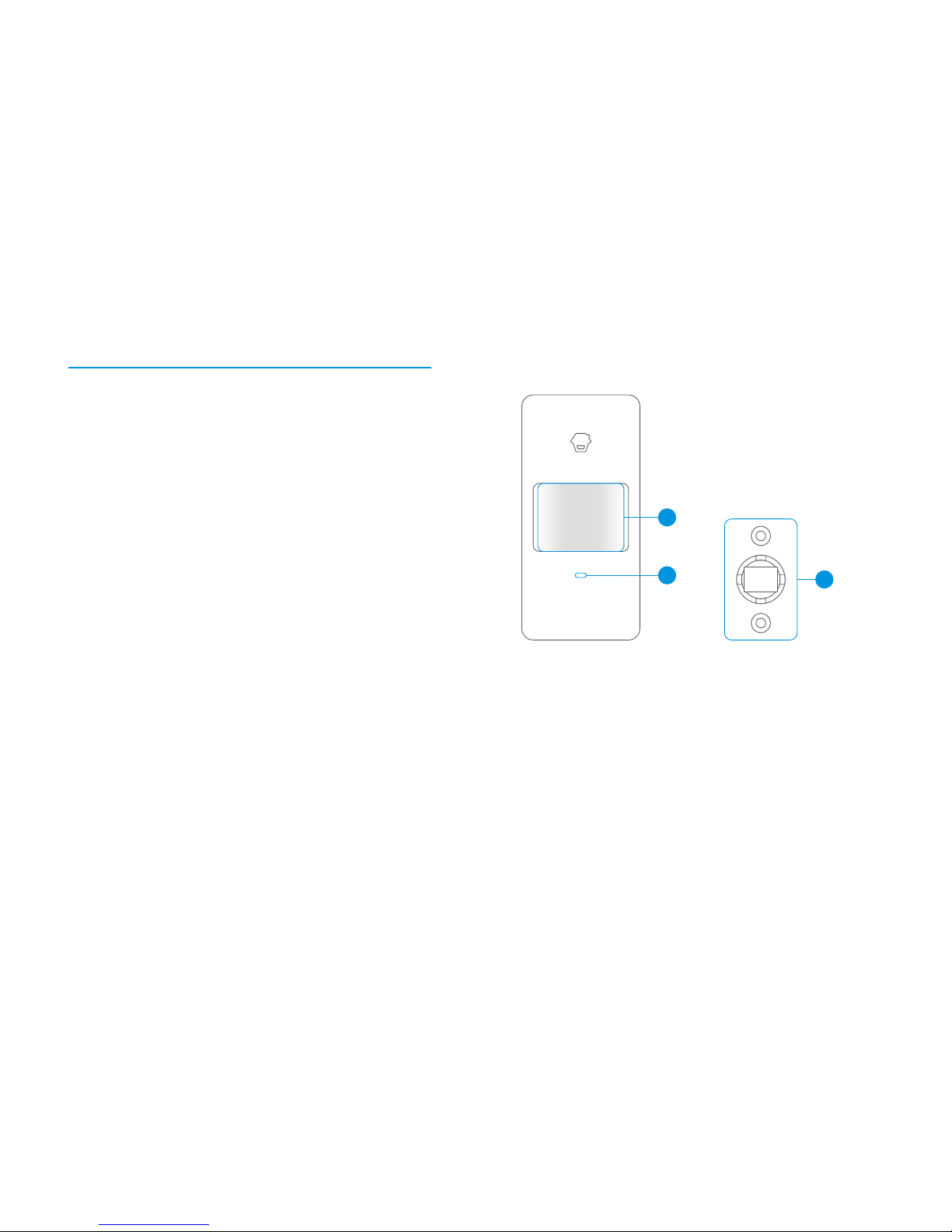
Appearance
1
2
3
1. De tection w indow
2. LE D indicat or
3. Br acket
LED Indication
Flash continuously:
Flash once:
Flash twice:
Flash once per 3 secon ds :
Under the self-testing state.
Int ruder is de tected.
Self-testing is finished, enter s the wo rking mod e.
Under voltage indication , pl ease
cha nge the batteries immed iately.(User wi ll get aler t SMS about
the low ba tter y if the PIR detector is con ne cted to the GSM
alarm system.)
Page 25
44
43
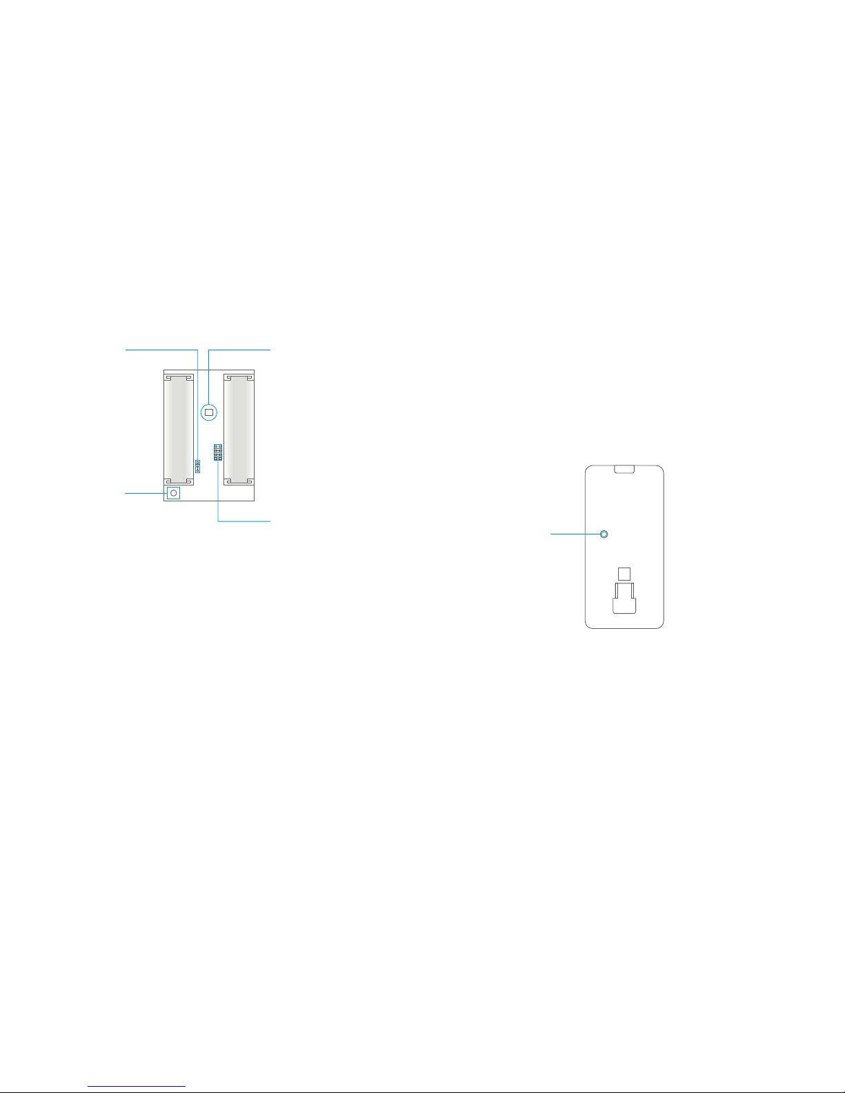
PCB Layout
AA 1.5V L R6
AA 1.5V L R6
Inf rared sensor
Zon e setting
LED O N / OFF
Tampe r switch
Infrared sensor :
Tamper switch:
It detects the infrared rays released by human
body motion, please don’t touch the sur face and always keep
it clean.
Once the case is opened in working state,
the tamper switch will be triggered and then generates an
alarm signal.
Mode Setting
Test Button
Testing mod e:
After self-testing, press the test button, the sensor enters testing
mod e, and de tects on ce ever y 10 secon ds . Af ter 3 minutes, the
LED flashe s twice, and the sensor enters the working mod e.
Usage
Remove the batter y activation strip to activate batteries. It will
star t self-testing for one mi nu te.
Page 26

46
45
In wo rking state, if the sensor is trigg ered twi ce within 3 minutes,
it wi ll enter sleepi ng mod e to save po we r. After no mov emen t
within next 3 mi nu tes, the sensor go es back to the working mod e.
Press the connect key on the alarm panel, and then press the
test button of the sensor twice to send alarm signal. Whe n on e
beep is he ard, the y are con ne cted.
To check if they are con ne cted suc cessfully, arm the system, and
trigger the sens or aga in, if the re is an alarming, the connection
is successful.
Working mod e:
Connect to alarm pan el:
Installation & Notices
2m
Ground
Avoi d mou nting the de tector close to wi nd ow s, air con di tion er,
heater, refrige rator, oven, su ns hi ne and places wh ere the
temperatur e changes fast or the air stream flow s frequently.
If two detector s are ins talled in the same detection scope,
please adj us t the location to avoi d inter ference and false alarm.
Top view
Sid e view
Page 27

48
47
Fix the br acket on the wall wi th screws and attach the detector
to the bracket. Ad just installation height or br acket to change
the detection di stance and angle. It is re comme nded to mou nt
it at the height of 2m from the ground.
The detector is mor e sensitive to the cro ss mov emen t than to
the ver tical mov emen t, so the performance of detector is best
when the detection direction is ver tical to the walking direction
of people.
Detection Scope
2m
4m
6m 8m0m
0m
2m
110 °
Top view
Sid e view
Testing (Walk Test)
A. Af ter installation , po we r on the detector. After on e mi nu te
self-testing, press the test button, walk in the scope (from
left to right or from righ t to left) and wa tch the LED indicator
to mak e sure the detector is working .
B. The LED ind icator flashes once wh en body
mov emen t is detected.
C. Ad just the de tector ang le accor di ng ly to achi eve the best
detection effect.
Page 28
49
Specifications
Power sup pl y
Static cur rent
Alarm current
Detection scop e
Transmitting distanc e
Radio frequenc y
Housing mat erial
Operation condition
Detector dimen sion s (L x W x H)
Bracket di men sions (L x W x H)
DC 3V (AA 1.5V LR6 Batter y x 2 pcs)
≤ 50uA
≤ 9.5mA
8m/ 110°
≤ 80m (in open are a)
315MHz or 433MHz (± 75KHz)
ABS plastic
Tempe rature: -10°C~55°C
Relative humi dity: ≤80% (non -con de ns ing)
108 x 52 x 36.8 mm
52 x 30 x 26.5 mm
50
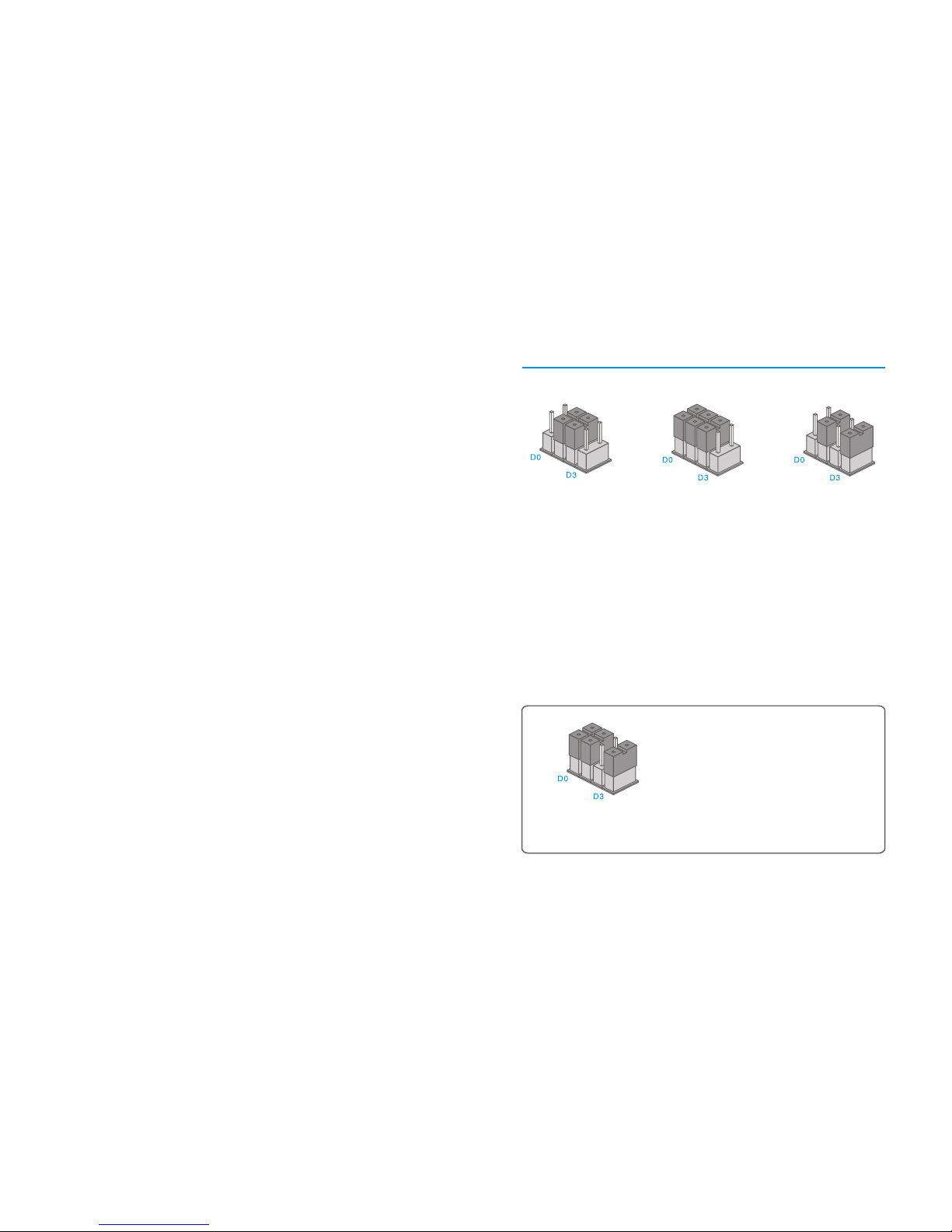
Zone Setup for Wireless Sensors
Home Mode Zone Normal Zone
The PIR motion detector is set in Home Mode Zone in default.
It is recommended to set Door/Window Contact on entrance
in Single Delay Zone.
Users should reconnect the detector with the control panel after
the zone is changed.
Sin gle Delay Z one
24-H Zone
Note: In any condition, the system will alarm immediately once the detector in
this zone is triggered.It is recommended to set smoke detector, gas detector
and outdoor beam sensor at 24-H zone.
Page 29
产品型号
CG-G5
林寿
说明书
设 计
印刷尺寸
工 艺
部件名称
材 料
版 本
注:
双色、双面印刷
成品尺寸
105X145mm
80克书写纸
骑马钉-56P
210X145mm
PA: OI-G5-EN-1309-V2.2-UK
 Loading...