

Page 1

A11
Security Alarm System
Printed in China
PA: A11-UM-EN-V1.0
2014 Chuango. All rights reserved.
Page 2
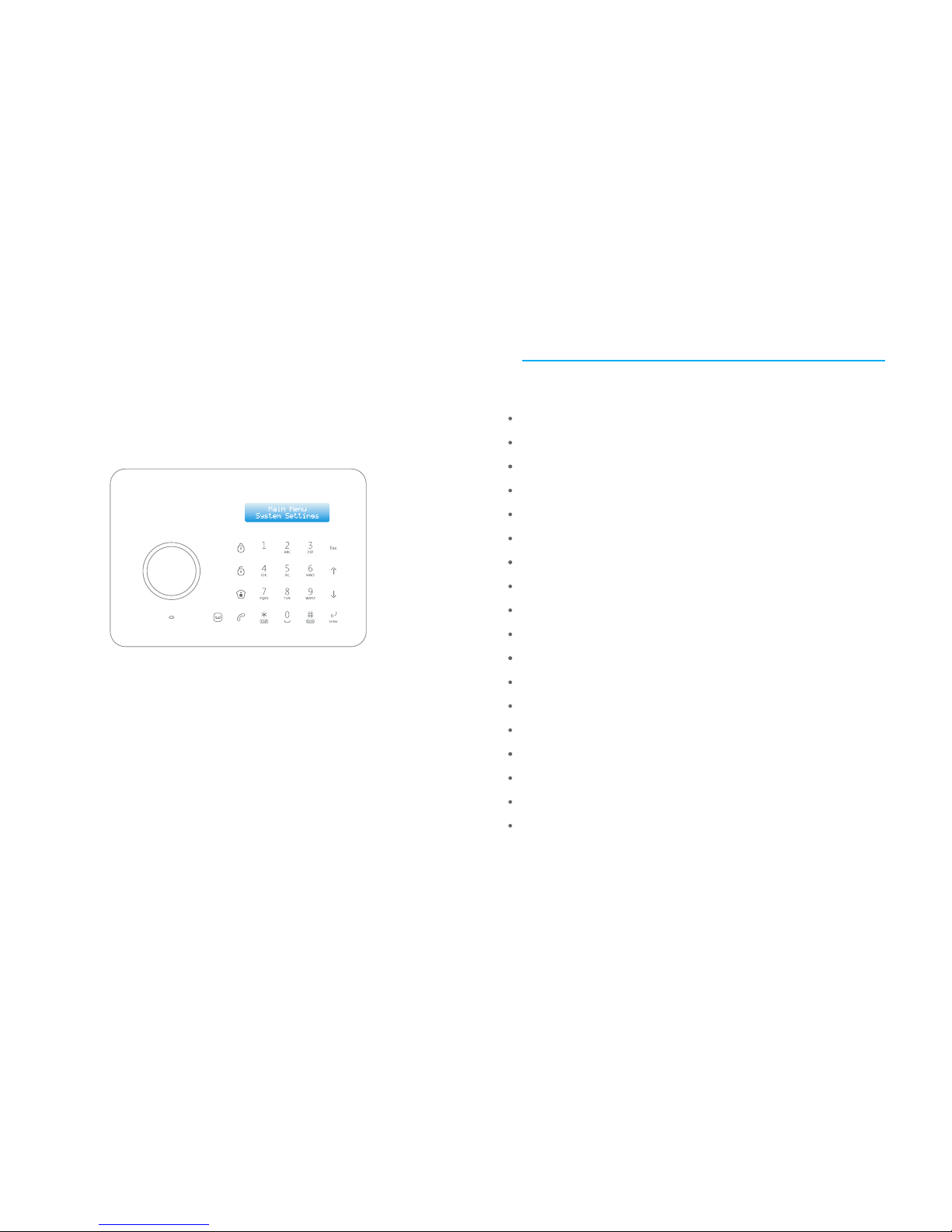
PSTN/LCD/RFID
Touch Alarm System
Please read this user manual carefully before using
Please kindly keep this user manual for your reference
when necessar y.
Features
100% wireless configuration, D.I.Y. installation
Fashion design with digital touch keypad
LCD display with guide menu, easy for programming
ARM + Auror high quality CPU
Built-in 1, 000, 000 RF codes combination maintains high reliability
Support 10 remote controls, 50 wireless sensors and 50 RFID tags
Store 6 alarm phone numbers and 2 ADEMCO CID CMS numbers
10 seconds voice memo and alarm voice message recordable
Disarm the system by RFID tags and unlock the electronic door lock
Support low power feedback and tamper alarm for wireless sensors
Support maximum 150 alarm event logs
Control panel can dial calls directly
Remote arm, disarm and monitor by phone operation
Duress code enables sending out alarm notification mutely
One group of timing arm and disarm
Support exit/entry delay
Rename all zones and RIFD tags
Voice prompt during phone remote control
Page 3

Table of Contents
Included Accessories
Control Panel Layout
Preparation before Use
1~ 2
3~ 4
5~ 6
Power on
Connect PSTN Land Line
Installation
Control Panel Operation
Alarm Control
Access Control System
Dial Calls
Voice Memo
Function Setting
LCD Display Contents
LCD Display Menu
Settings
Alarm Phone Number Setup
Add/Delete /Edit Accessories
System Settings
Date and Time
Entry/Exit Delay
Backlight Time
Timed Arm / Disarm
Edit Greeting Message
Remote Phone Control
Linecut Alarm
7~ 9
10
11 ~13
14 ~28
Connect to Electronic Lock
Connect to CMS Center
Add CMS Phone Number
Delete CMS Phone Number
User ID
Upload Arm/Disarm Report
Contact ID Reports
Precautions
FAQ
Wireless Remote Control
Wireless Door/Window Contact
Pet-Immune PIR Motion Detector
29
29 ~30
31
32
33
34 ~36
37 ~40
41 ~49
Keypad Tones
Access Code
Ringing Times for Phone Remote Control
Alarm Message
Siren Setup
User ID for CMS
Upload Arm Report
Upload Disarm Report
Reset
Check Event Logs
Specifications
Page 4
2
1
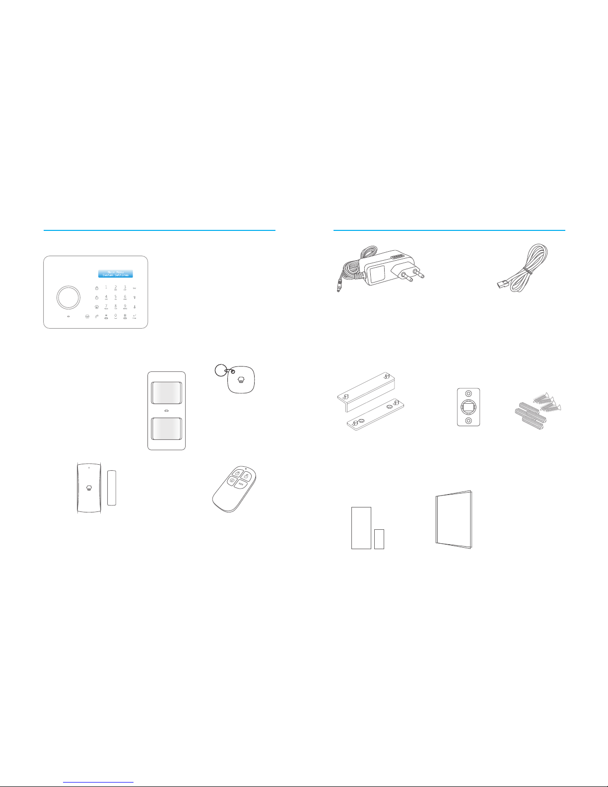
Included Accessories
The control panel is known as the “heart and brain”
for alarm system, which is used for receiving and
processing signals from wireless sensors and remote
controls. Users can make settings freely with the
keypad and LCD display. In case of emergency, the
panel hoots on site and dials the pre-stored alarm
phone numbers automatically. When users pick up the
phone, they are able to hear alarm voice message
and choose to monitor on site or disarm the system.
The wireless PIR Motion Detector is an
intelligent passive infrared motion sensor,
designed to detect human movements
within an approximate range of 6 to 8
meters from the detector. The detector
includes fuzzy logic to minimize false alarms
from unwanted heat sources. With power
saving feature, the detector will enter
sleeping mode after the second activation
within 3 minutes to save power.
CG-A11 Control Panel x1
Pet-Immune PIR Motion Detector x 1
Wireless Remote Control x 2
The remote control is compact and
portable; it is convenient to carry it to arm,
disarm, part arm the alarm system and also
make an emergency call.
Wireless Door/Window Contact x 1
The Door/window contact can be installed on
doors, windows and any other objects that open
and close. The sensor transmits signals to the
control panel when a magnet mounted near the
sensor is moved away.
RFID Tag x 2
The RFID tag is for disarming
The system and unlocking the
electronic door lock (if
connected).
AC Adapter x 1
Supply power to the control panel. In case
of power failure, two built-in backup
batteries in the panel will support 5-hour
standby.
Telephone Cable x 1
Connect PSTN land line to the control panel. In
case of emergency, the panel will hoot on site and
call the pre-stored alarm phone number to notify
users.
Brackets (wall-mounted and
desktop) for control panel x 2
Bracket for PIR Motion
Detector x 1
Double-sided tape for
Door/Window Contact x 1
Screws x 4
User Manual x 1
Page 5
4
3
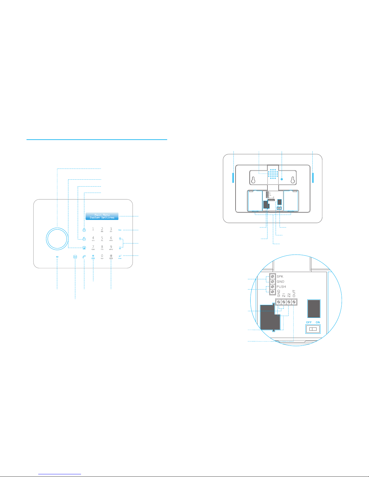
RFID Tag Re ad er /
Play Voi ce Memo
Home M od e (Par t A rm )
Disa rm
Arm
Voice Me mo Butt on
Stat us I ndica tor
Rea r Side
LCD Dis pl ay
Esc
Up/D ow n
Ente r
SOS
Clea r
Call
Fron t Sid e
Control Panel Layout
Buzz er
Tamper Sw it ch Spea ke r
Back up B atter ies
AC Ad apter I nterface
Power O N/ OFF
PSTN L an d Line In ter face
Inte rfa ce s for
Wired Sens ors
MIC
Outp ut W ired Siren
≤( 500m A)
Outp ut f or Elec tron ic
Lock
NC Inp ut f or
Wired Sens or
(24H Z on e)
NC Inp ut f or
Wired Sens or
(Norma l Zone)
Outp ut
Page 6
6
5
Preparation before Use
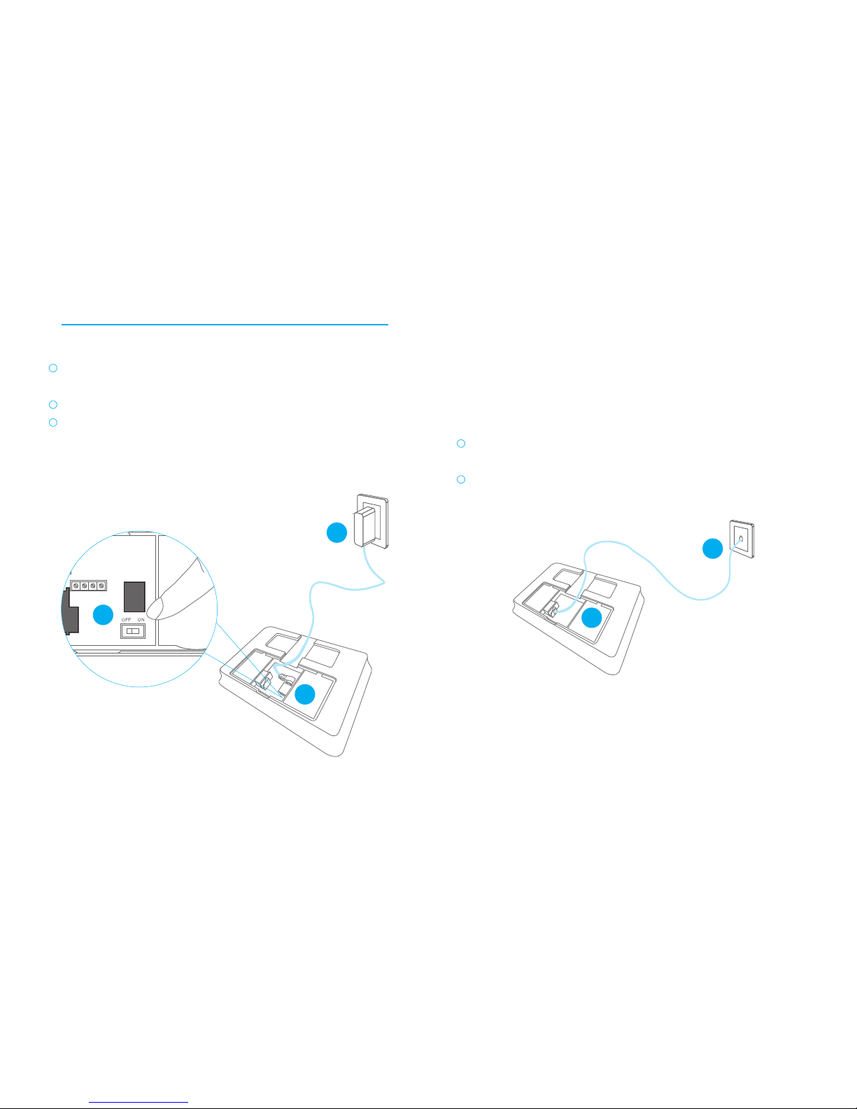
Plug the output connector of AC adapter into the adapter interface of
control panel.
Plug the AC adapter to wall power socket.
Turn the power switch from OFF to ON.
1. Power on
1
2
3
2. Connect PSTN Land Line
A11 is a PSTN alarm system which will auto dial the pre-stored phone
number when the system detects intruders. Please make sure the panel
has been connected to PSTN land line to ensure safety.
1
2
Connect the smaller connector of provided telephone cable to the PSTN
land line inter face at the back side of the panel.
Connect the other end of the telephone cable to the signal output
provided by PSTN land line operator.
3. Installation
1) Wall Mounting
Fix the wall mounting bracket on the wall with screws.
Wedge the panel on the bracket, make sure they fit well.
2) Standing on the Desk
Mount the desktop bracket, and then put it on the desk.
2
3
1
1
2
Page 7
8
7
Control Panel Operation
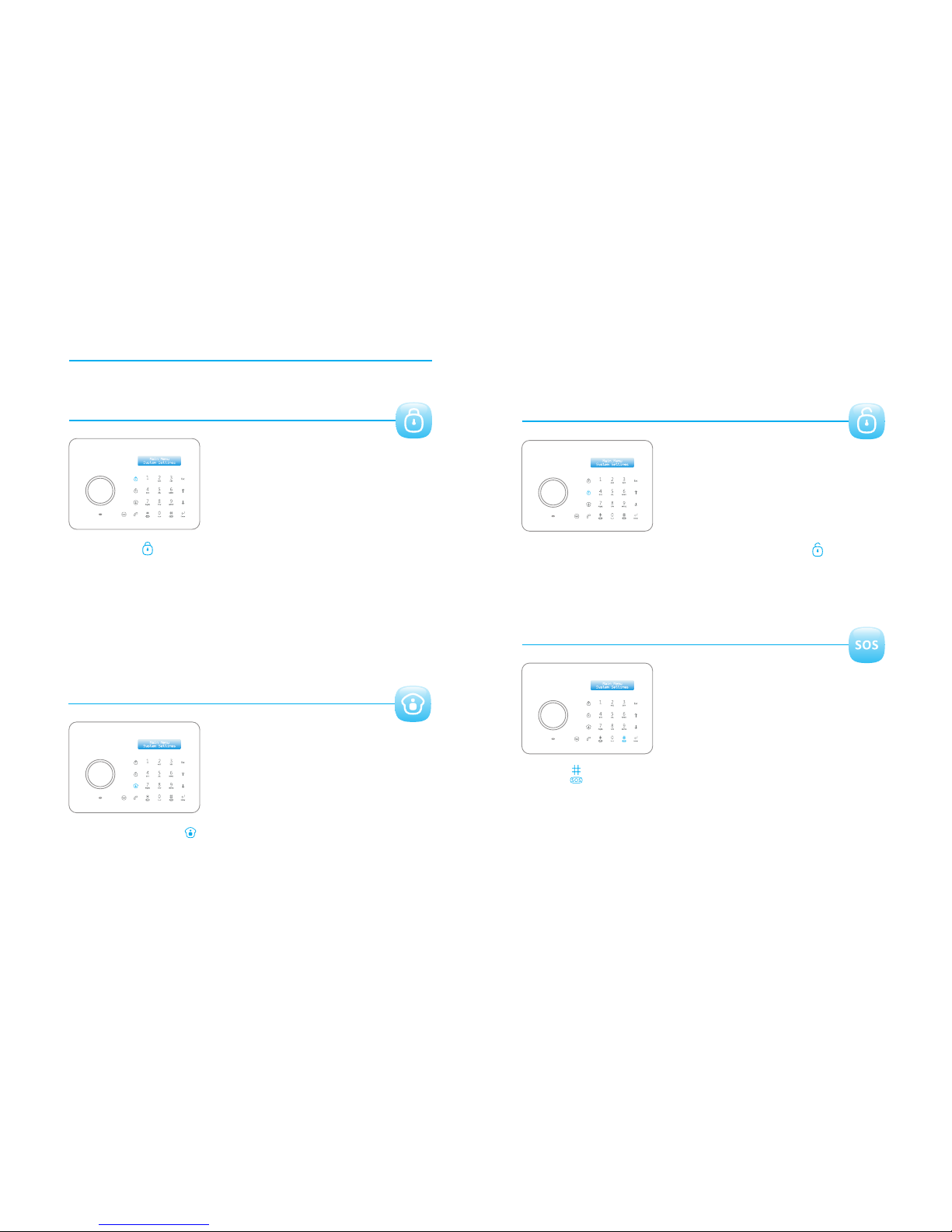
1. Alarm Control
Arm (Away Arm)
Press the button on the control panel, the system enters Arm [Arm ]
state when one beep is heard and the Arm LED Indicator lights on.
Note!
If Entry/Exit Delay is activated, all zones except the 24-hour zone will enter Arm state
after the set delay time.
The Delay Sensors will enter Arm state after the set delay time.
Home Mode (Part Arm)
Press the button on the control panel, the system enters [Home Mode ]
Home Mode when one beep is heard and the Home Mode LED Indicator
lights on. All the Normal Sensors are armed except the Home Mode
Sensors which are disarmed so that users can move freely at home.
Disarm
Input user code or admin code first, then press the button, [Disarm ]
the system enters Disarm state when one beep is heard and the Disarm
LED Indicator lights on.
Emergency Call
Hold the button for 3 seconds when the LCD display is activated, the [ ]
system goes into emergent alarming state with siren hooting, meanwhile
the panel will auto dial pre-stored alarm phone numbers.
Page 8

The control panel has a RFID reader for unlocking the electronic door lock
by disarming the system. Just place the RFID tag close to the RFID reader,
the green LED indicator flashes once.
The system is disarmed and the electronic door lock is open (If connected)
2. Access Control System
3. Dialing Calls
The control panel has a built-in call module. Make sure the PSTN land line
is connected and the credit is enough, you can use the panel to make calls.
When the control panel is in Disarm or Home Mode state, press
[Call ] [Call ] button, input the phone number and press button
again, the line will get through. If you input wrong numbers, press [Esc]
button and input again. Press button to cancel dialing or press [Esc]
[Call ] button to end a conversation.
4. Voice Memo
Press the button to record 10 seconds voice [Record Voice Memo ]
message. The Play Voice Memo circle will be flashing in blue to remind
you. Users can touch the center of circle to listen to the voice memo. The
LED indicator blacks out when the voice memo has been played. Replay
by touching it again.
5. Function Setting
Input the admin code, and then press to enter setting menu. [Enter]
Up ConfirmEnter
Down Back to last step Esc
LCD Display Contents
System Status
Display content
Stand-by
Arm or Disarm
Alarm
Line Disconnect
AC Power Failure
Panel Low Battery
System
Arm
System
Disarm
System
Home Arm
Remote
Arm
Remote
Disarm
Remote
Home Arm
RFID 1-50(RFID Name)
Disarm
Alarm
SOS
Alarm
Linecut
Alarm
Panel Tamper
Alarm
Sensor Tamper
Alarm
Wired Sensor
Alarm
Sensor 1-50(Sensor Name)
10
9
Sensor 1-50(Sensor Name) Low Battery
Page 9

When LCD is activated, input the admin code, and then press to [Enter]
enter setting menu.
LCD Display Menu
Main Menu
Sub Menu 1 Sub Menu 2 Sub Menu 3
Accessories
Alarm Number1-6
CMS Number1-2
Alarm Number1-6
CMS Number1-2
Add
Delete
Add
Delete
Edit Name
Add
Delete
Edit
Add Phone
Number
Del Phone
Number
Remote &
Keypad
RFID Tag
Wireless
Sensors
Test Mode
ALL
Remote (01-10)
ALL
RFID (01-50)
RFID (01-50)
ALL
Sensor (01-50)
Sensor (01-50)
Edit Sensor Type (Normal Sensor,
24 Hour Sensor, Delay Sensor,
Home Sensor)
Edit Sensor Name
Phone
Numbers
System
Settings
Date And Time
Entry Exit Delay
Backlight Time
<20S>
Auto Arm/
Disarm
Edit Welcome
Control by
Phone
Linecut Alarm
Keypad Tones
Access Code
Ringing Times
Date
Date Format
Time
Entry Delay <000S>
Exit Delay <000S>
Auto Arm Time
<00:00:00>
Auto Disarm Time
<00:00:00>
On
Off
Admin Code
User Code
Duress Code
On
Off
On
Off
Input 6 Digits
<Default Code 123456>
Input 4 Digits
<Default Code 1234>
Input 4 Digits
<Default Code 1111>
Alarm Message
Record
12
11
Add Please Connect
Add Please Connect
Add Please Connect
Page 10

Settings
1. Alarm Phone Number Setup
User can set 6 user phone numbers and 2 CMS phone numbers. When
connecting to CMS, system will dial CMS phone number to upload
Contact ID reports while alarming and then dial 6 user phone numbers in
sequence one by one. System will dial all the user phone numbers in 3
cycles until the phone is answered or any press on phone buttons.
Log on the menu, choose “Phone Numbers”, press . [Enter]
Press or , choose “Add Phone Number ”, press . [ ] [ ] [Enter]
Press or , choose “Alarm Number1~6”, press . [ ] [ ] [Enter]
Input alarm phone number s in order, press . If group extended [Enter]
telephone number is used, 0# or 9# need to be added in front of the
phone number.
1
2
3
4
Add Alarm Phone Number
Note!
If user want to check or edit the stored phone number, enter “A larm N umbe r1~6 ”to
check and edit.
Delete Alarm Phone Number
Note!
If user wants to set CMS center phone number, pleas e refer to “Connect to CMS
Center ”.
Log on the menu, choose “Phone Numbers”, press . [Enter]
Press or , choose “Delete Phone Number ”, press . [ ] [ ] [Enter]
Press or , choose “Alarm Number1~6”, press . [ ] [ ] [Enter]
Delete the alarm phone numbers in order, press again[Enter]
1
2
3
4
History
System
Settings
Siren Setup
User ID<1234>
Arm Upload
Disarm Upload
Reset
Wired Siren
Wireless Siren
Built-in Siren
Siren Alert Time
<300S>
Input 4 Digits
On
Off
On
Off
Siren On/Off <On/Off>
Arm/Disarm Tone <On/Off>
Siren On/Off <On/Off>
Arm/Disarm Tone <On/Off>
Siren On/Off <On/Off>
Arm/Disarm Tone <On/Off>
14
13
When LCD is activated, input the admin code, and then press to [Enter]
enter setting menu.
Page 11

Log on the menu, press or , choose “Accessories”, press . [ ] [ ] [Enter]
Press or , choose “RFID Tag”, press . [ ] [ ] [Enter]
Press or , choose “Add”, press . [ ] [ ] [Enter]
LCD display will show “Please connect”, put the RFID tag close to the RFID
reader on the control panel. When a beep is heard, LCD display will show
“RFID (01-50)”, connection succeeded.
1
2
3
4
Log on the menu, press or , choose “Accessories”, press . [ ] [ ] [Enter]
Press or , choose “Remote & Keypad”, press . [ ] [ ] [Enter]
Press or , choose “Add”, press . [ ] [ ] [Enter]
LCD display will show “Please connect”, press any button from the remote
control to enable signal transmitting to the control panel. When a beep is
heard, LCD display will show “Remote (01-10)”, connection succeeded.
1
2
3
4
2. Add/Delete/Edit Accessories
The control panel only receives signal from accessories after they are
connected to the control panel.
Add/Delete Remote Controls or Wireless Keypads
Add
Delete
If user wants to delete the added remote controls or RFID wireless keypads,
please choose “Delete” in the step as above and press . Then [Enter]
choose to delete all or specific remote controls or wireless keypads, press
[Enter] again.
3
Add/Delete/Edit RFID Tags
Add
Log on the menu, press or ,choose “Accessories”, press . [ ] [ ] [Enter]
Press or , choose “Wireless Sensors”, press . [ ] [ ] [Enter]
Press or , choose “Edit”, press . [ ] [ ] [Enter]
Press or , choose “Sensor 01-50”, press . [ ] [ ] [Enter]
Press or , choose “Edit Sensor Type”, press . [ ] [ ] [Enter]
Press or , choose one type of “Normal Sensor/ 24 Hour Sensor/ [ ] [ ]
Delay Sensor/ Home Sensor ”, press . [Enter]
1
2
3
4
5
6
Delete
If user wants to delete the added RFID cards or tags, please choose
“Delete” in the step as above and press . Then choose to delete [Enter]
all or specific RFID cards or tags, press again. [Enter]
3
Edit
If user wants to rename the added RFID cards or tags, please choose “Edit
Name” in the step as above and press , then input the name. [Enter]
3
Add/Delete/Edit Wireless Sensors
Log on the menu, press or , choose “Accessories”, press . [ ] [ ] [Enter]
Press or , choose “Wireless Sensors”, press . [ ] [ ] [Enter]
Press or , choose “Add”, press . [ ] [ ] [Enter]
LCD display will show “Please connect”, trigger the detector once to make
it send wireless signal to the control panel. When a beep is heard, LCD
display will show “Sensor (01-50)”, connection succeeded.
1
2
3
4
Add
Delete
If user wants to delete the added sensors, please choose “Delete” in the
step as above and press . Then choose to delete all or specific [Enter]
wireless sensors, press again. [Enter]
3
Edit
Type of Sensors
Note!
If two beeps is heard when coding , the accessory i s code d alrea dy.
16
15
Note!
When adding wireless keypad to control pan el, pl ease e nter a cces s code a nd the n
press "arm" or "disarm" button on the wireless keypad. When a "beep' is heard , the
system is connected to the panel successfully.
Page 12

1
2
3
Normal Sensor : In armed mode, when normal sensors are triggered,
alarm system will alarm. In disarmed mode, when normal sensors are
triggered, alarm system will not alarm.
24 Hour Sensor : Under any circumstances, when 24 Hour Sensors are
triggered, alarm system will alarm at once.
Delay Sensor : If user wants to use the entry and exit delay, related sensors
need to be set in entry and exit delay zone. When setting is done, after set
delay time, those sensor s will make system alarm. Refer to Entry and
Delay Setup for details.
Home Sensor: In home mode, only normal sensors will be triggered for
alarming while home sensors will not be triggered. This will allow user to
move freely at home.
If user wants to rename the sensors, please choose “Edit Sensor Name” in
the step and press . Then input the sensor name. [Enter]
Names of Sensors
5
Test Mode
Test if the sensors are connected successfully to the control panel.
Log on the menu, press or , choose “Accessories”, press . [ ] [ ] [Enter]
Press or , choose “ Test Mode”, press . LCD display will [ ] [ ] [Enter]
show “Yes?”, Press again to start testing mode for 10 minutes. [Enter]
Please trigger coded sensors in order, the sensors will transmit signals to
control panel. When 3 beeps are heard, LCD display will collect the
triggering time of the sensors. Then you can count the connected sensors
based on the numbers displayed on the LCD screen. Exit by pressing [Esc]
button.
3. System Settings
3.1 Date and Time
Press or , choose “Date and Time”, press . [ ] [ ] [Enter]
Press or , choose “Date”, press . [ ] [ ] [Enter]
Input date, press [Enter].
1
2
Log on the menu, press or , choose “System Settings”, press . [ ] [ ] [Enter]
Date Format
Press or , choose “Date and Time”, press . [ ] [ ] [Enter]
Press or , choose “Date Format”, press . [ ] [ ] [Enter]
Press or , choose format, press . [ ] [ ] [Enter]
1
2
Log on the menu, press or , choose “System Settings”, press . [ ] [ ] [Enter]
Time
The default time is on 24 hours standard.
Press or , choose “Date and Time”, press . [ ] [ ] [Enter]
Press or , choose “ Time”, press . [ ] [ ] [Enter]
Input , press .current time [Enter]
1
2
Log on the menu, press or , choose “System Settings”, press . [ ] [ ] [Enter]
Date
If user is not used to taking along with the remote control, entr y and exit
delay could be set in the system. Following is the operation instruction for
arming and disarming.
When entr y and exit delay is set, user could exit the house in set time
period, then system will be armed automatically; when user is back
without disarming the system, entry delay will allow time for user to
disarm the system. Other wise, the system will treat this as an intrusion and
it will be triggered and send out alarming alert.
Note!
The entry and exit delay is only for delay sensors.
18
17
3
4
3
4
3
4
3.2 Entry and Exit Delay
Page 13

Entry Delay
Log on the menu, press or , choose “System Settings”, press . [ ] [ ] [Enter]
Press or , choose “Entr y Exit Delay”, press . [ ] [ ] [Enter]
Press or , choose “Entr y Delay”, press . [ ] [ ] [Enter]
Input time for entr y delay; press for confirmation. [Enter]
Entr y delay time is calculated on seconds; default is 0 second (off); setup
range is 0-999 seconds.
1
2
3
4
Exit Delay
Exit delay is set to leave time for user to exit and then arm the system
within the set time.
Log on the menu, press or , choose “System Settings”, press . [ ] [ ] [Enter]
1
2
3
4
Press or , choose “Entr y Exit Delay”, press . [ ] [ ] [Enter]
Press or , choose “Exit Delay”, press . [ ] [ ] [Enter]
Input time for exit delay; press for confirmation.[Enter]
Exit delay time is calculated on seconds; default is 0 second (off); setup
range is 0-999 seconds.
User can set standby time for the backlight on the blue LCD display
accordingly.
Log on the menu, press or , choose “System Settings”, press . [ ] [ ] [Enter]
1
2
3
4
Press or , choose “Backlight Time”, press . [ ] [ ] [Enter]
Input time for backlight time; press . [Enter]
Backlight time is calculated on seconds; default is 20 seconds; setup range
is 01-99 seconds.
Entr y delay is set to leave time for user to disarm the system before the
sensors send signal to control panel after triggering after the set time.
User can set timed arm and disarm according to daily schedule to avoid
repeated operation.
Timed Arm
Log on the menu, press or , choose “System Settings”, press . [ ] [ ] [Enter]
1
2
Press or , choose “Auto Arm/Disarm”, press . [ ] [ ] [Enter]
Press or , choose “Auto Arm Time”, press . [ ] [ ] [Enter]
Input exact time for arming; press .[Enter]
3
4
Timed Disarm
1
2
Log on the menu, press or , choose “System Settings”, press [ ] [ ]
[Enter] for confirmation.
Press or , choose “Auto Arm/Disarm”, press . [ ] [ ] [Enter]
Press or , choose “Auto Disarm Time”, press . [ ] [ ] [Enter]
Input exact time for disarming; press . [Enter]
3
4
When greeting message is set; turn on the alarm system or activate the
touch keyboard; the greeting message will be shown on LCD display.
Log on the menu, press or , choose “System Settings”, press . [ ] [ ] [Enter]
1
2
Press or , choose “Edit Welcome”, press to define the [ ] [ ] [Enter]
greeting message.
[ ] [ ] [ ] means to delete, means to space, means to move backward,
[ ] means to move for ward.
Once delay time is set, when arm the system, one beep will be heard
ever y second to remind the user to leave, the reminding rhythm will
speed up in the last 15 seconds.
20
19
3.3 Backlight Time
3.4 Timed Arm / Disarm
3.5 Edit Greeting Message
Page 14

3.6 Remote Phone Control
Users can set to turn on/off remote phone control to get free access to
the alarm system for arming, disarming and on site monitoring by dialing
telephone no. of the system
Turn On/Off Remote Phone Control
Log on the menu, press or , choose “System Settings”, press . [ ] [ ] [Enter]
Press or , choose “Control by Phone”, press . [ ] [ ] [Enter]
Press or , choose “On” or “Off ”, press . [ ] [ ] [Enter]
“On” is to turn on phone remote control; “Off ” is to turn off phone remote
control.
Default setting is “off ”, Remote Phone Control off.
1
2
3
Remote Phone Control Operation
When alarm system is triggered, the control panel will dial pre-stored user
phone numbers. When pick up the phone, users can follow the voice
prompt to control the panel remotely af ter recorded voice is heard. (See
Instruction Table Below)
Method 1
Method 2
User dials alarm system telephone no.; after getting through, alarm
system will guide you to input access code.
Input access code (user code or admin code); Press . []
Alarm system plays the voice prompt twice to explain the functions.
User chooses the related instruction to make remote control operation.
(See Instruction Table Below)
1
2
3
4
Note!
Alarm s yste m will h ang up a fte r 30 sec onds w ith no o pera tion .
Remote Phone Control Instruction Table
When linecut alarm function is on, the control panel will alarm once the
PSTN land line is cut or pulled out.
Turn On/Off Line Cut Alarm
Log on the menu, press or , choose “System Settings”, press . [ ] [ ] [Enter]
1
2
Press or , choose “Linecut Alarm”, press . [ ] [ ] [Enter]
Press or , choose “On” or “Off ”, press . [ ] [ ] [Enter]
“On” is to turn on the linecut alarm; “Off” is to turn off the linecut alarm.
Default setting is “On”, the linecut alarm is on.
3
User can turn on/off keypad tone accordingly.
Turn On/Off Keypad Tone
Log on the menu, press or , choose “System Settings”, press . [ ] [ ] [Enter]
1
2
Press or , choose “Keypad Tone”, press . [ ] [ ] [Enter]
Press or , choose “On” or “Off ”, press . [ ] [ ] [Enter]
“On” is to turn on the keypad tone; “Off ” is to turn off the keypad tone.
Default setting is “On”, keypad tone is on.
3
4
Phone
Buttons
Function
Explanation
Press [ ]
Press [ ]
Press [ ]
Press [ ]
Press [ ]
Press [ ]
Press [ ]
Press [ ]
Arm the system
Disarm the system
Monitor on site
Turn on siren
Turn off siren
Turn on relay
Turn off relay
To exit Remote Phone Control
Phone voice prompt “Arm Succeed”
Phone voice prompt “Disarm Succeed”
Press [*] to prolong monitor time
Deter the intruders
Siren stops ringing
Available for the system with RS-1000
relay module
Or hang up the phone
22
21
3.7 Linecut Alarm
3.8 Keypad Tone
Page 15

All the alarm panels are with default user code, admin code and duress
code. Please change all codes before using and keep your codes secret.
Admin Code
With admin code, user can arm and disarm, make system settings as well
as reset codes etc.
Log on the menu, press or , choose “System Settings”, press . [ ] [ ] [Enter]
1
2
Press or , choose “Access Code”, press . [ ] [ ] [Enter]
Press or , choose “Admin Code”, press . [ ] [ ] [Enter]
LCD display will show “Input 6 Digits”, then input 6 digits for code, press
[Enter].(Default Admin Code: 123456)
Input the new admin code, press .[Enter]
3
4
5
User Code
With user code, user can set arm, home mode and disarm the alarm
system.
Log on the menu, press or , choose “System Settings”, press . [ ] [ ] [Enter]
1
2
Press or , choose “Access Code”, press . [ ] [ ] [Enter]
Press or , choose “User Code”, press . [ ] [ ] [Enter]
LCD display will show “Input 4 Digits”, then input 4 digits for code, press
[Enter].(Default User Code: 1234)
Input the new user code, press .[Enter]
3
4
5
Duress Code
In case of emergency, when user is violently requested to disarm the
system, it's recommended to use the duress code to disarm the alarm
system. The panel will silently dial alarm telephone numbers stored.
1
2
3
4
Log on the menu, press or , choose “System Settings”, press . [ ] [ ] [Enter]
Press or , choose “Access Code”, press . [ ] [ ] [Enter]
Press or , choose “Duress Code”, press . [ ] [ ] [Enter]
LCD display will show “Input 4 Digits”, then input 4 digits for code, press
[Enter].(Default Duress Code: 1111)
Input the new duress code, press .[Enter]
5
3.10 Ringing Times for Remote Phone Control
After the set ringing times, user can make system settings from remote
calling, such as arming/disarming the system.
1
2
Log on the menu, press or , choose “System Settings”, press . [ ] [ ] [Enter]
Press or , choose “Ringing Times”, press . [ ] [ ] [Enter]
Input 5~9 for ring times, press .[Enter]
Default setting is 5 times.
3
3.11 Alarm Message
User can leave 10 seconds voice message when control panel makes call
to user's stored phone number, voice record will be repeatedly played to
notify the intrusion.
Record Alarm Voice
1
2
3
4
Log on the menu, press or , choose “System Settings”, press . [ ] [ ] [Enter]
Press or , choose “Alarm Message”, press . [ ] [ ] [Enter]
Press or , choose “Record”, press . [ ] [ ] [Enter]
LCD display will show “Record 10s Voice” to remind you of the 10 seconds
voice recording, press .[Enter]
Star t voice recording for 10s until the system stops automatically, or press
[Enter] to stop recording.
5
24
23
3.9 Access Code
Page 16

3.12 Siren Setup
Users can turn on/off wired siren, wireless siren, built-in siren as well as
arm/disarm beep, and set siren ringing time.
Wired Siren
Wired siren is connected to the control panel by wire.
Turn On/Off Wired Siren
Log on the menu, press or , choose “System Settings”, press . [ ] [ ] [Enter]
Press or , choose “Siren Setup”, press . [ ] [ ] [Enter]
Press or , choose “Wired Siren”, press . [ ] [ ] [Enter]
Press or , choose “Siren On/Off ”, press . [ ] [ ] [Enter]
Press or , choose “On” or “Off ”, press [ ] [ ] [Enter]
“On” is to turn on the wired siren; “Off” is to turn off the wired siren.
Default setting is “On”; the wired siren is on.
1
2
3
4
5
Turn On/Off Arm/Disarm Beep for Wired Siren
Log on the menu, press or , choose “System Settings”, press . [ ] [ ] [Enter]
Press or ,choose “Siren Setup”, press . [ ] [ ] [Enter]
Press or ,choose “Wired Siren”, press . [ ] [ ] [Enter]
Press or ,choose “Arm/Disarm Beep”, press . [ ] [ ] [Enter]
Press or , choose “On” or “Off ”, press [ ] [ ] [Enter]
“On” is to turn on arm/disarm beep for wired siren; “Off ” is to turn off
arm/disarm beep for wired siren.
Default setting is “On”; arm/disarm beep is on.
1
2
3
4
5
Wireless Siren
Wireless siren is connected to control panel through wireless connection.
Turn on/off wireless siren
Log on the menu, press or , choose “System Settings”, press . [ ] [ ] [Enter]
Press or , choose “Siren Setup”, press . [ ] [ ] [Enter]
Press or , choose “Wireless Siren”, press . [ ] [ ] [Enter]
Press or , choose “Siren On/Off ”, press . [ ] [ ] [Enter]
Press or , choose “On” or “Off ”, press [ ] [ ] [Enter]
“On” is to turn on the wireless siren; “Off” is to turn off the wireless siren.
Default setting is “On”; the wireless siren is on.
1
2
3
4
5
Turn On/Off Arm/Disarm Beep for Wireless Siren
Log on the menu, press or , choose “System Settings”, press . [ ] [ ] [Enter]
Press or , choose “Siren Setup”, press . [ ] [ ] [Enter]
Press or , choose “Wireless Siren”, press . [ ] [ ] [Enter]
Press or , choose “Arm/Disarm Beep”, press . [ ] [ ] [Enter]
Press or , choose “On” or “Off ”, press [ ] [ ] [Enter]
“On” is to turn on arm/disarm beep for wireless siren; “Off ” is to turn off
arm/disarm beep for wireless siren.
Default setting is “On”; arm/disarm beep is on.
1
2
3
4
5
Built-in Siren
Built-in siren is the siren inside the control panel
Turn On/Off Built-in Siren
Log on the menu, press or , choose “System Settings”, press . [ ] [ ] [Enter]
Press or , choose “Siren Setup”, press . [ ] [ ] [Enter]
Press or , choose “Built-in Siren”, press . [ ] [ ] [Enter]
Press or , choose “Siren On/Off ”, press . [ ] [ ] [Enter]
Press or , choose “On” or “Off ”, press [ ] [ ] [Enter]
“On” is to turn on the built-in siren; “Off” is to turn off the built-in siren.
Default setting is “On”; the built-in siren is on.
1
2
3
4
5
26
25
Page 17

3.16 Reset
Note!
All system settings will be restored t o defa ult se ttin g. Res et will not delete the
accessories that has already coded to the contro l pane l.
Log on the menu, press or , choose “System Settings”, press . [ ] [ ] [Enter]
1
2
Press or , choose “Reset”, press to reset the system to [ ] [ ] [Enter]
default setting.
Turn On/Off Arm/Disarm Beep for Built-in Siren
Log on the menu, press or , choose “System Settings”, press . [ ] [ ] [Enter]
Press or , choose “Siren Setup”, press . [ ] [ ] [Enter]
Press or , choose “Built-in Siren”, press . [ ] [ ] [Enter]
Press or , choose “Arm/Disarm Beep”, press . [ ] [ ] [Enter]
Press or , choose “On” or “Off ”, press [ ] [ ] [Enter]
“On” is to turn on arm/disarm beep for built-in siren; “Off ” is to turn off
arm/disarm beep for built-in siren. Default setting is “On”; arm/disarm
beep is on.
1
2
3
4
5
Siren Ringing Time
Set Ringing Time for All Sirens
Press or , choose “Siren Setup”, press . [ ] [ ] [Enter]
Press or , choose “Siren Aler t Time”, press . [ ] [ ] [Enter]
Input the ringing time, press .[Enter]
Siren ringing time is calculated as seconds, default setting is 300 seconds.
If 0 second is set, siren will not ring
Log on the menu, press or , choose “System Settings”, press . [ ] [ ] [Enter]
1
2
3
4
Please see details at Page 29: Connect to CMS
3.14 Upload Arm Report
Please see details at Page 29: Connect to CMS
3.15 Upload Disarm Report
Please see details at Page 29: Connect to CMS
28
27
If user forgot the admin code and cannot setup the system, please contact
local distributors.
Log on the menu, press or , choose “History”, press . [ ] [ ] [Enter]
Check Event Logs
Users can check the event logs freely. 150 event logs are traceable.
1
2
3
Press or , choose the event log you need to track, press . [ ] [ ] [Enter]
Relevant event log time and alarm way will be shown.
3.13 User ID for CMS
Note!
Hold or to skip the event logs.[ ] [ ]
Page 18

30
29
Connect to Electronic Lock
Please ignore this if user is not intended to put this alarm as access control.
This alarm only sends on/off signal to electronic door lock, please refer to
related electronic door lock manual for details.
Connect to CMS Center
Please ignore this step if users don't need to connect to CMS center.
When connected to CMS center, control panel will upload contact ID to
CMS center automatically once intrusion is detected.
Add CMS Phone Number
When CMS center phone no. is stored, the control panel will auto dial to
CMS center when alarm.
Press or , choose “CMS Number1”or “CMS Number2”, press . [ ] [ ] [Enter]
1
2
3
4
Log on the menu, choose “Phone Numbers”, press .[Enter]
Press or , choose “Add Phone Number ”, press . [ ] [ ] [Enter]
Input CMS number no., press . If group extension telephone no. is [Enter]
used to connect to the CMS center, please add 0# or9# before the phone
no. you plan to store.
Note!
If user wants to check or edit the pre-stored ph one no ., ent er “CM S Numb er1~ 2” to
check or edit.
Delete CMS Phone Number
1
2
3
4
Log on the menu, choose “Phone Numbers”, press .[Enter]
Press or , choose “Del Phone Number ”, press . [ ] [ ] [Enter]
Press or , choose in order “CMS Number1~2”, press . [ ] [ ] [Enter]
Delete stored CMS phone no., Press . [Enter]
User ID
1
2
3
Log on the menu; press or , choose “System Settings”, press . [ ] [ ] [Enter]
It is supplied by CMS center. After it is stored, CMS center can exactly
know user ’s location according to the ID number.
Press or , choose “User ID”, press . [ ] [ ] [Enter]
LCD display will show “Input 4 Digits”, input 4 digits user ID, press .[Enter]
Upload Arm/ Disarm Report to CMS Center
1
2
3
When this function is enabled, all arm/disarm reports will be uploaded
automatically to CMS center, so that CMS center can know the status of
the alarm system.
After the User ID is set, press or to choose “Arm Upload” or [ ] [ ]
“Disarm Upload”, press .[Enter]
Press or , Choose “On”, press . [ ] [ ] [Enter]
When choosing “Off ” during setup , press , arm/ disarm repor t [Enter]
will not be uploaded to CMS center.
2
Contact ID Reports
Arm
Disarm
Disarm by RFID tag
PIR detector alarm
Door contact alarm
Emergency call
Duress alarm
Home mode (part arm)
Control panel tamper alarm
Sensor tamper alarm
Normal zone alarm
24H zone alarm
Sensor low battery
Control panel low battery
Control panel AC failure
Event Code
Event Event
Event Code
3401
1401
1409
1132
1131
1100
1120
3456
1137
1144
1140
1133
1384
1302
1301
Page 19

Precautions
To prevent harm to users or other people during usage of the product and
to extend the lifespan of the product, please follow the precautions below:
General Instruction
The wireless accessories should be connected to the control panel before use.
Low power voltage would affect transmitting distance range.
2 cells of 3.7V/800mAh battery backup or standard power adapter for power supply.
All accessories from our company are compatible with this control panel.
Do not press SOS key if there is no emergency to avoid disturbing neighborhood.
Check the system regularly to ensure the system works properly in case of emergency.
The control panel is neither waterproof nor moisture-proof, please install it in a shady,
cool and dry place.
The case of the control panel is made of ABS. Please keep it away from strong light
for a longer lifespan.
Forbiddance
The control panel is non explosion-proof. Please keep it away from fire, flame sources.
Install the control panel away from objects such as heater, air conditioner, microwave
oven etc. that produces heat or electric-magnetic.
Forbiddance of Decomposition
Take the control panel for disposal of recycling according to the local regulation.
Disassembly for this product can not be done by non-professionals.
FAQ
Phenomena
Cause of Malfunction
Troubleshoot Method
No response from
control panel
operation
Accessories cannot
connect to control
panel
No response from
the control panel
by operating
remote control
RFID card/tag fail
to disarm
Touch keyboard fail
to make related
setting
Power switch is off
A/C Power failure
Lithium battery backup
power exhausted
Panel not in learning
status
Accessories not triggered
for learning
When learning, 2 beeps
are heard from panel
Remote control is not
learned to control panel
Out of range between
remote control and panel
RFID car/tag not connected
to the panel
Not logged onto the
setting menu.
Open battery compartment,
turn on the power
Contact local main power
supply bureau
Connect to main power with
adapter
Make sure the panel set in
learning status
Make sure the triggered
accessories transmitting signal
to panel for learning
This means accessory has
been coded already
Follow the manual and connect
the remote control to panel
No more than 80 meters in
open area
(no interference)
Signal repeater could be added
Follow the work manual and
code RFID card/tag to the panel
Input the correct admin code,
press and log on menu [ Enter ]
setting
32
31
Page 20
Specifications
Product Name
PSTN/LCD/RFID Touch Alarm System
Model No.
CG-A11
Power Supply
Input: DC 12V 500mA, 6Wh
Standby Current
≤ 90mA
Alarm Current
≤ 300mA
Backup Battery
2 Cells of 3.7V 800mAh Li-ion Battery(BL-5B)
Internal Siren Volume
95dB
Radio Frequency
433.92MHz (
±75KHz)
Maximum Stored Phone No.
6 alarm Phone No. and 2 CMS No.
Maximum Remote Controls
10 pcs
Maximum Sensors
50 pcs
Maximum RFID Tags
50 pcs
Maximum Event Logs
150 events
Housing Material
ABS plastic
Operation Condition
Temperature : -10°C~ +55°C
Relative Humidity : 80% (non-condensing)
Dimension (L x W x H)
185x130x27mm
≤
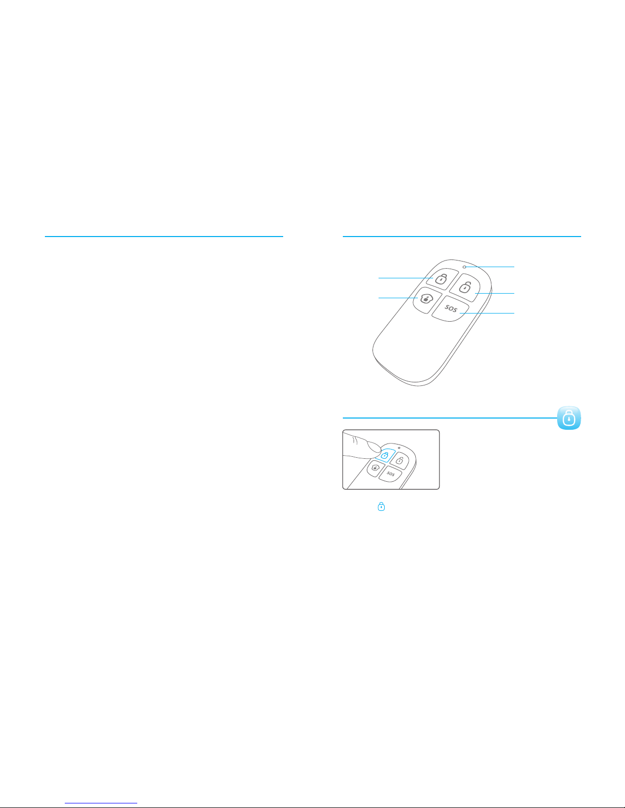
Wireless Remote Control
LED Indicator
Disarm
Arm
Stay
Panic
Arm
The delay sensors will be armed after delay time.
34
33
Press button on the remote control, the system enters Arm state [Arm ]
when one beep is heard and the Arm LED Indicator lights on.
Note! If Exit Delay is activated, all zones except the 24- ho ur z on e wi ll e nt er A rm
state af te r th e se t de la y ti me .
Page 21
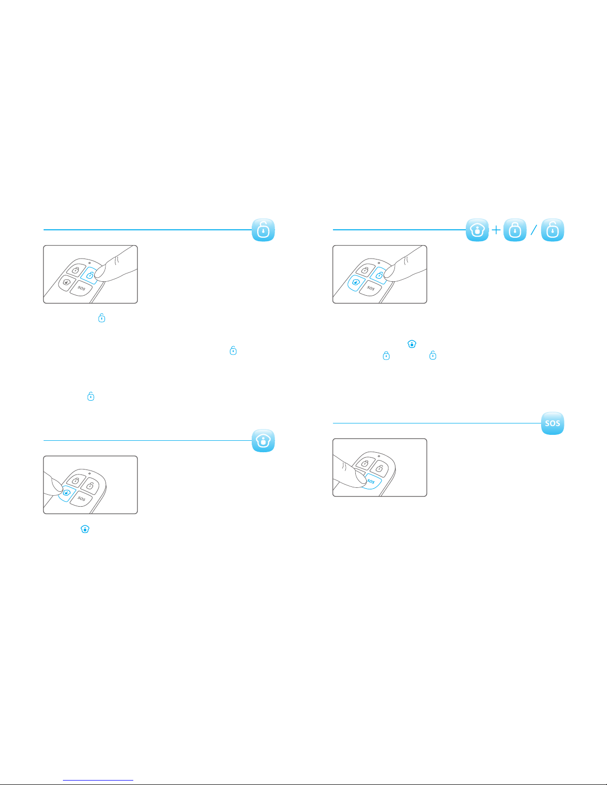
Disarm
Home Mode
Press the button on the remote control, the system enters [Disarm ]
Disarm state when two beeps are heard and the Arm LED Indicator goes out.
When alarm is activated, the siren will hoot. Press the button, [Disarm ]
the system is disarmed after two beeps are heard, and the Disarm LED
Indicator lights on. But the LED indicator of triggered zone keeps flashing
for further checking.
Press button again, the alarmimg zone indicator goes out.[Disarm ]
Press button on the remote control, the system enters Home [ Stay ]
Mode when one beep is heard and the Home Mode LED Indicator lights on.
All the Normal Sensors are armed except the Home Mode Sensors which are
disarmed so that users can move freely at home.
Mute Mode
When arm or disarm the system, the control panel will beep once or twice.
If siren beep is not needed, operation as follows:
Press and hold the button on the remote control for 1 second, [Stay ]
then press or button within 3 seconds. The system is [Arm ] [Disarm ]
armed or disarmed in mute without disturbing other people.
Emergency Call
In any condition, once the button on the remote control is pressed, [ SOS ]
the system goes into emergent alarming state with siren hooting, meanwhile
the panel will auto dial pre-stored alarm phone numbers.
36
35
Page 22
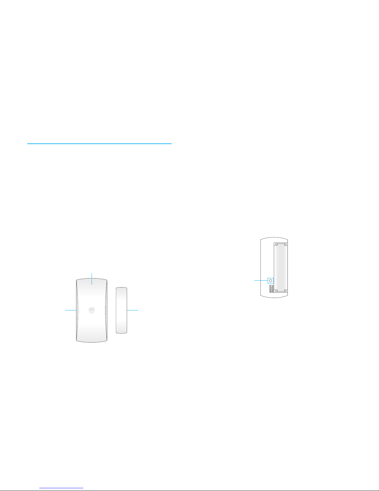
Wireless Door/Window Contact
Appearance
Features
LED i ndicato r
Transmitter
Mag net
The D WC-102 is a D oor/Windo w Contact t hat can be inst alled on do or s,
win dows, and a ny other obje cts that op en and close. T he sensor t ransmits
sig nals to the c ontro l panel whe n a magnet moun ted near th e sensor is
mov ed away. External in put for wired access or y is availab le at the N/C
int er fa ce. The tamper pro tection ens ures th at sabota ge attempts to
mov e the conta ct will result in an a larm activa tion.
38
37
AA 1.5 V LR 6
LED Indication
Ta mper swit ch
PCB Layout
LED flashes on ce: Door/wi ndow is ope ned and trans mitter se nds signal to
the control panel.
Low p ower indi cation, ple ase chang e batter y as Fla sh once per 3 s econds:
soo n as possib le.
Page 23
Installation & Notice
Rem ove the bat ter y activat ion strip, th e sensor wi ll enter working state
imm ediatel y.
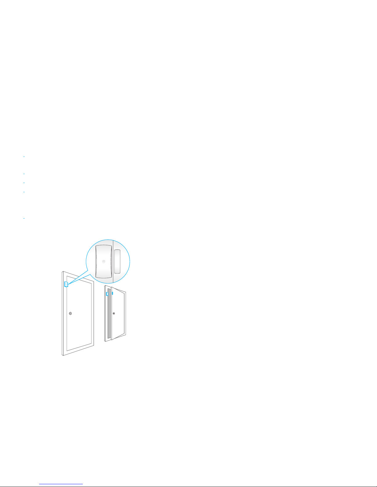
Mou nt the sens or on the door frame and the m agnet on th e door.
Mak e sure the magnet is o n the right s ide of the transmi tter
Pla ce the tran smitter in the desired locati on, mount t he magnet no more
tha n 1cm away from t he transm itter and sec ure the transmit ter and mag net
wit h double- sided tapes or screws.
Avoi d mounting se nsors in areas with a la rge qua ntity of metal
or el ectrica l wiring, such as a furnac e or utilit y room.
40
39
Specifications
Power supply
DC 1.5V (AA 1.5V LR6 Batter y x 1pc)
Stat ic cu
rrent
≤ 35u A
Alarm current
≤ 40mA
Transmitting distance
≤80 m (in open area)
Radio freq uency
433.9 2MHz (±75KHz)
Housing material
ABS p lastic
Operating Co ndition
Te mperature -10°C~+55° C
Rel ative hum idity ≤ 80% (non-conde nsing)
Transmitte r dimensions ( L x W x H )
71 x 34 x 17.5mm
Magnet dimen sions ( L x W x H )
51 x 12 x 13.5m m
Page 24
42
41
Pet-Immune PIR Motion Detector
Features
PIR -910 is a hig h performance wireless P. I.R. motion detector. It co nsists of
dig ital dual -core f uzzy logi c infrared control chip a nd intellig ent analysis
whi ch effect ively identif y in terf erenc e signals f rom bod y movement signals
and redu ce false alar m rate. Wit h automatic t emperat ure com pensati on and
ant i-air tur bulence tec hnology, it eas ily adapt s to environmental changes.
The d etector a lso has the adv antages of ene rgy sav ing, re liability and easy
ins tallati on. The detec tor featu res pet i mmunity f or small anim als up to 25k gs.
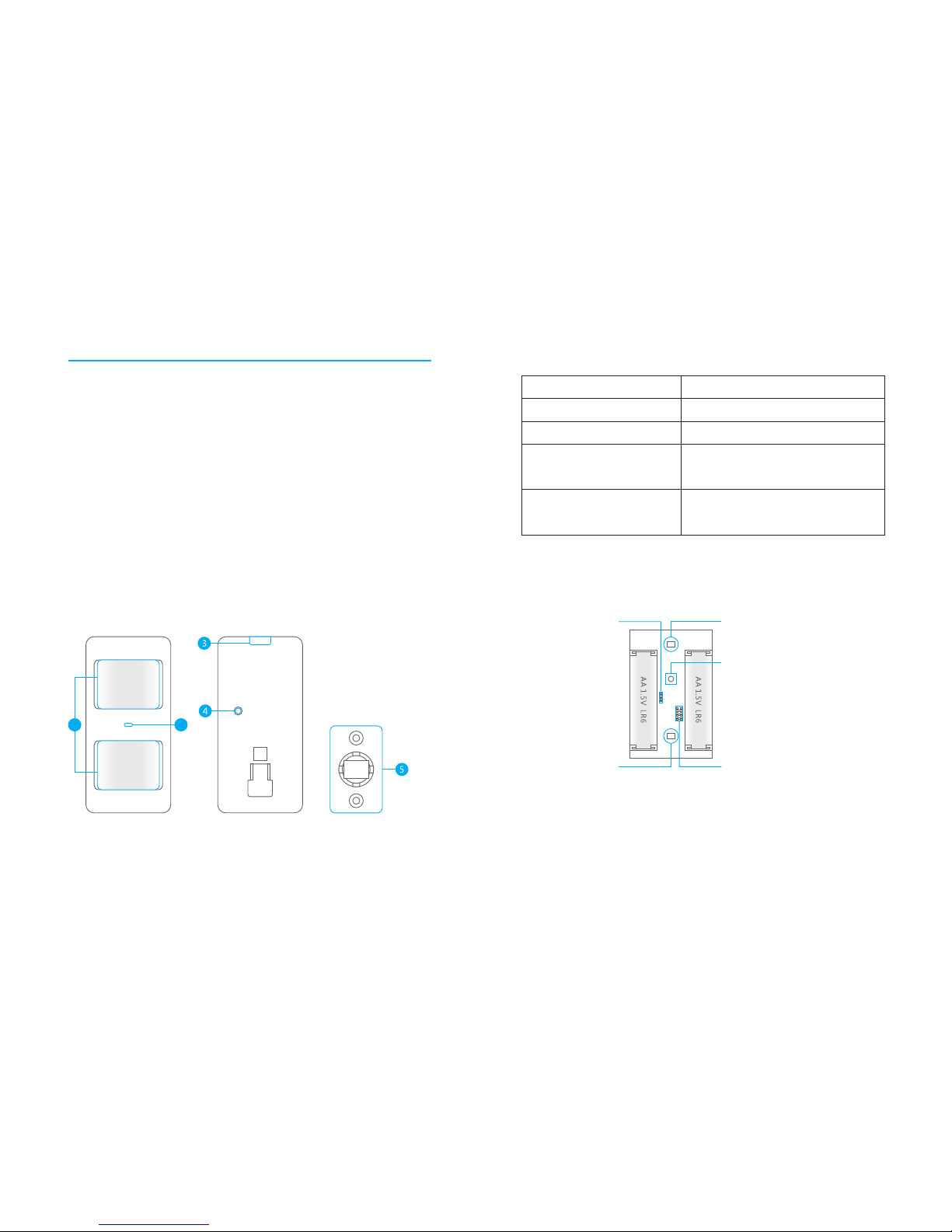
Appearance
1. Detection window
2. LED indicator
3. Snap joint
4. Test button
5. Bracket
1
2
Inf rared s ensor: I t detects the i nfrared rays released b y human bod y
motion, plea se don’t touch the surface and always keep it c lean.
Onc e the case is o pened in working state , the tampe r Tamper swi tch:
swi tch will be t riggered and the n generates a n, alarm si gnal.
LED Indication
Blink once
Blink twice
Blink once every 3 seconds
Intrusion detected
Testing mode is finished, the detector
enters power-saving mode
Low battery, please replace the battery
as soon as possible
Display
Meaning
Blink continuously
Self testing
PCB Layout
LED ON / OFF
Infrared sensor
Tamper switch
Zone setting
Infrared sensor
Page 25
44
43
WorkingMode
Testing mode
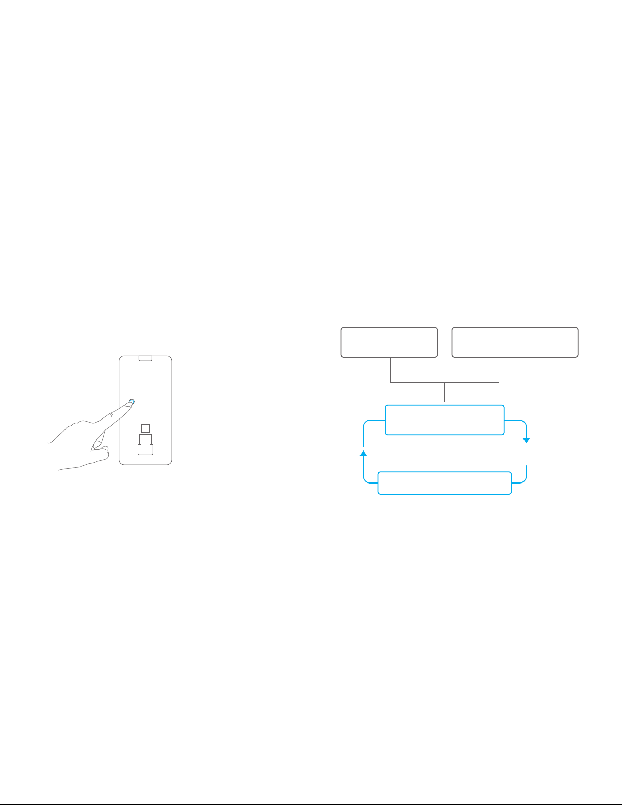
After self-testing, the detector enters testing mode, and detects once every
10 seconds. After 3 minutes, the LED blinks twice, and the detector enters
power saving mode.
Hold the test button and load the battery, then release the test button, the
detector stands in testing mode, it keeps detecting once every 10 seconds.
Exits this status by reloading the battery without holding the test button.
Power saving mode
The product features power-saving design. If the detector detects human
movement twice in 3 minutes, it will switch to the sleeping state to save
power. At this time, the LED will not blink even human movement is
detected, and no alarm. After no movement within the next 3 minutes, the
detector switches back to the working state automatically.
Note: After the detector is in the sleeping state, ensure no human movement within 3
minutes; otherwise, the detector remains sleeping.
In the sleeping state, it is recommended that you leave the room after arming the system.
Ensure no human movement in 3 minutes. Then, go into the room, the system alarms
immediately.
Sle ep aft er detect ing human
mov ement twi ce
Cas e 2:
Press th e test button a nd then arm .
Cas e 1:
Ini tial star t and then arm .
3 min utes late r
Swi tch from sleep to arm.
No hu man movem ent
wit hin 3 minut es
Page 26
46
45
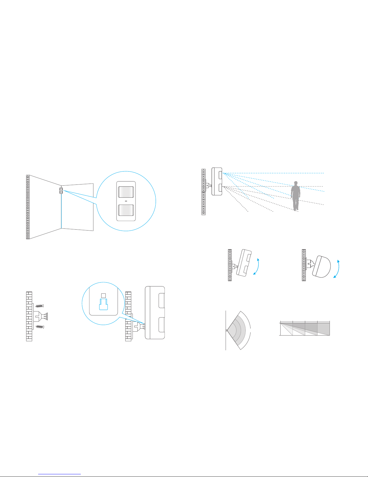
Detection Scope
2m
4m
6m 8m0m
0m
2m
110°
Top view
Side view
Test the PIR motion detector
Press the test button at the back. It switches to the testing mode and sustains
for 3 minutes. Walk in the detection scope and observe the LED. When body
movement is detected, the LED blinks once.
Side view
Top view
Adjust the angle
Adjust the bracket angle to achieve the best detection effect.
Note! If pet-immune function is applied, please do not adjust the angle up or down,
but keep it parallel with the wall
2m
Grou nd
Choose a suitable installation location
It is recommended to mount it at the height of 2m from the ground.
Fix the detector
Fix the bracket on the wall with screws and attach the detector to the bracket.
Installation
Page 27
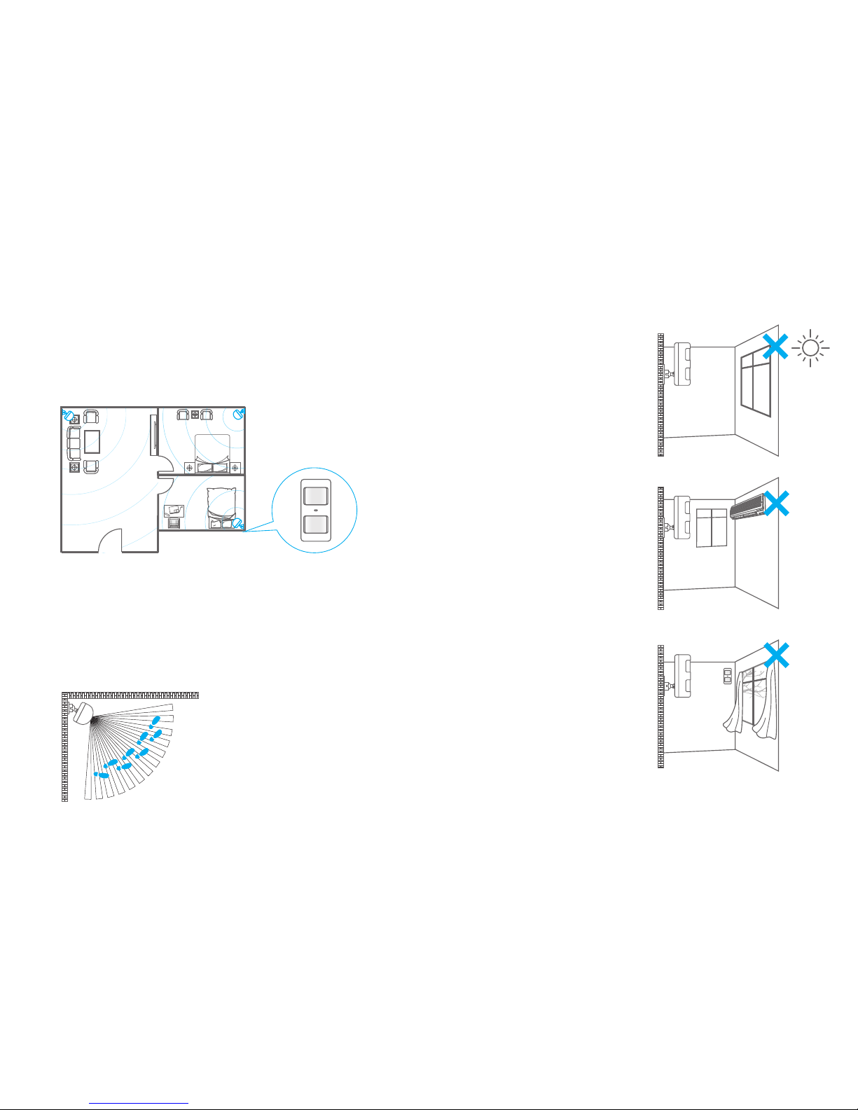
Don't face to swinging objects
Swinging objects may also trigger false
alarm. Besides, if there are two
detectors covering the save scope,
adjust the locations to prevent cross-
interference.
Don't face to or position close to heat
sources
Heat and cold sources, such as heat
extraction units, heaters, air
conditioner, microwave oven,
refrigerator, which may cause false
alarm, should be avoided.
ON
Don't face to glass windows or doors
Strong light interferes with detection
sensitivity. In addition, complicated
situations, such as traffic flow, stream
of people, also should be avoided.
Mount the detector in a proper angle
The installation angle affects detection sensitivity. The sensitivity is optimal
when the walk direction is vertical to the infrared direction. Choose the best
location and angle according to the actual situation and detection scope
diagram.
Mount the detector to a location close to the entry or exit
The detector aims at preventing intrusion. Detecting human movement at
the entry or exit is critical for security.
Installation Notices
48
47
Page 28

Specifications
Power Supply
DC 3V ( AA 1.2V LR6 Batte r y x 2 pc s)
Stat ic Curren t
≤ 90u A
Alarm Current
≤ 9.5 mA
Detectio n Scope
8m/ 110°
Pet Imm unity
≤ 25k g
Transmitting Distance
≤ 80m ( in open area)
Radio Freq uency
433 .92MHz (± 75KHz)
Housing Material
ABS p lastic
Operation Co ndition
Te mperature: -10°C~+55 °C
Rel ative Hum idity: ≤80% (non-con densing )
Detector D imensio ns (L x W x H)
10 8 x 52 x 36.8 mm
Bracke t Dimension s (L x W x H)
52 x 30 x 2 6.5 mm
49
 Loading...