

Page 1
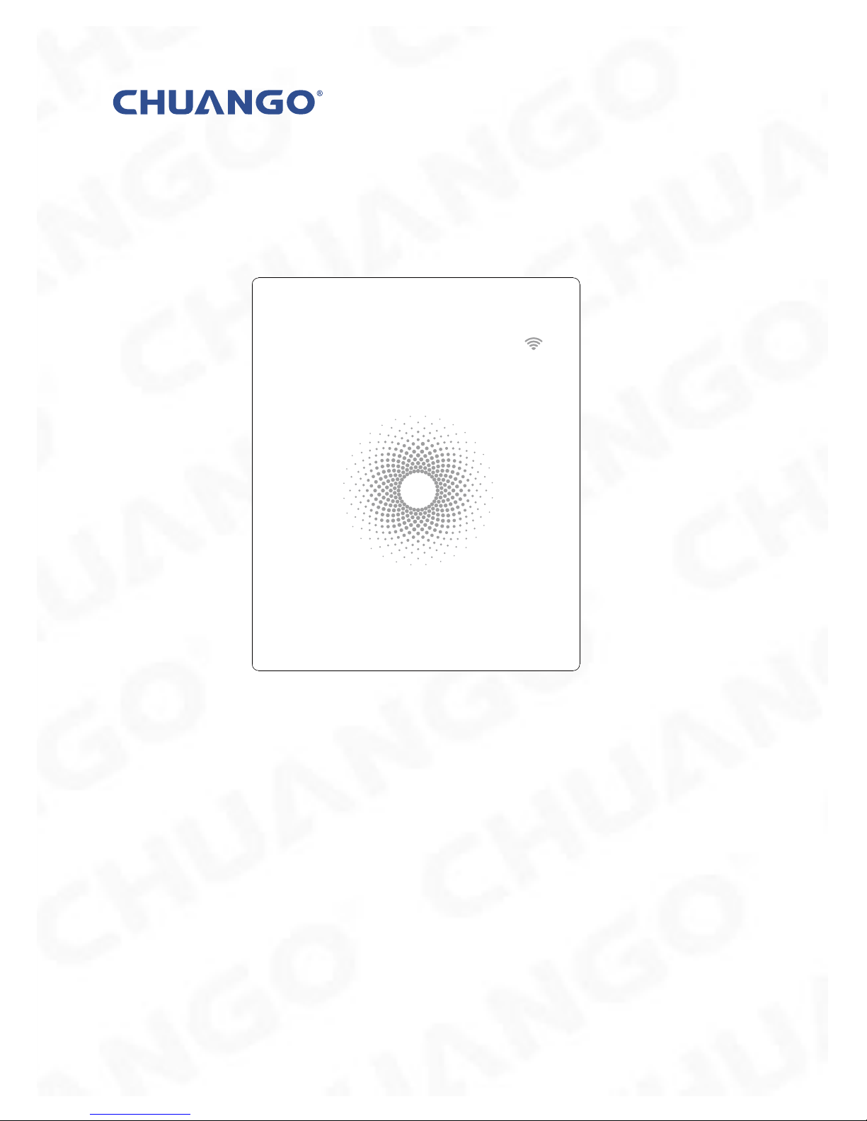
AW1 Plus
WiFi
Alarm System
User Manual
status
Page 2

Foreword
Congratulations on your purchase of the AW1 Plus Alarm system. Before you commence installation we recommend that you unpack the product, familiarise yourself
with the component parts, and carefully read through this instruction guide.
There are some parts of the installation must be completed in the order shown to
ensure successful installation.
Disclaimer
All statements, technical information and recommendations in this manual
are believed to be reliable, but the accuracy and completeness thereof are not
guaranteed or warranted.
The specications and information regarding the products as shown in this
document are subject to change without notice.
The reproduction, language translation modication, storage in a retrieval system
or retransmission, in any form or by any means, electronic, mechanical or otherwise,
is strictly prohibited without prior written permission.
In no event are we liable for any indirect, special, incidental, or consequential
damages, including, without limitation, lost prots or loss or damage to data arising
out of the use or inability to use this document.
Page 3

Contents
Packing List ............................................................................................................................................1
Hub ......................................................................................................................................................2~3
Remote Control .....................................................................................................................................4
Door/Window Contact .......................................................................................................................5
Pet-immune PIR Motion Dectector ........................................................................................... 6-7
Pairing New Accessories to the Hub .............................................................................................7
Getting Started ................................................................................................................................. 8-9
App Control and Settings ...........................................................................................................9-13
Interference Resistance ...................................................................................................................14
Installation ..................................................................................................................................... 15-18
Replacing Accessory Batteries ...................................................................................................... 19
FAQ ................................................................................................................................................... 20-21
Specications ............................................................................................................................... 22-23
Page 4
1
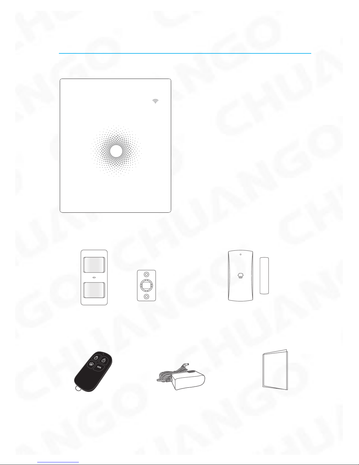
Packing List
1x AW1 Plus Hub
status
1x PIR-910 Pet-immune PIR Motion Sensor 1x DWC-102 Door/ Window Contact
2x RC-80 Remote Control 1x Power Adapter 1x User Manual
Page 5
2
Hub
All Sensors are wirelessly linked to the Hub.
In the event of alarm activation, for example, when a Sensor is triggered, a push
notification will automatically be sent to all registered users
The system can be controlled and monitored both on-site using the Remote Control
supplied and remotely from anywhere in the world, with the FREE iOS and Android
Apps.
The system can easily be expanded to include up to: 50 Wireless Sensors and 10
Remote Controls.
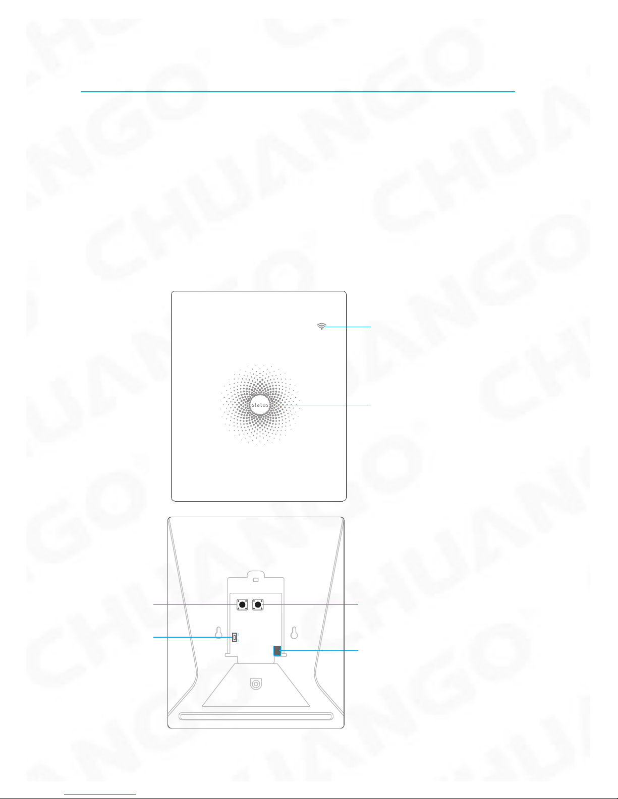
WiFi Indicator
Status Indicator
Network Configuration
Power Switch
AC Adapter Jack
Learn Button
Page 6
3
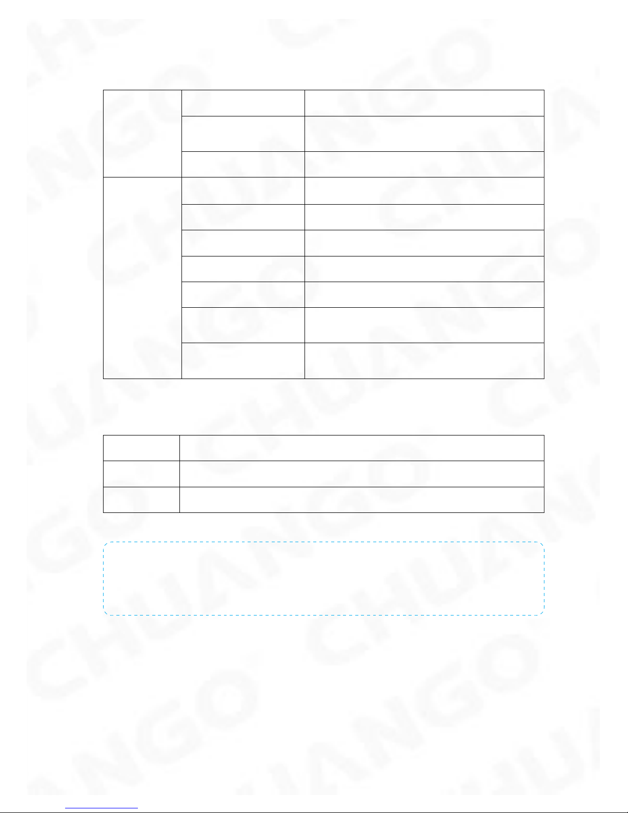
LED Indication
WiFi Indicator
(Blue)
Steady On Connected with Router
One ash per second
Searching for a network or disconnected
from Router
Off The Power Adapter is not plugged in
Status
Indicator
(Red, Blue
and Green)
Steady On Stable WiFi connection
Red System is Armed
Blue System is in Home Mode (Part Arm)
Green System is Disarmed
Blue light blinking Disconnected from the Router
Red light ashes
quickly
Alarm condition
Flashes every 3
seconds
Low battery
Functionality of Buttons behind the Back Cover
Learn Used to pair an accessory with the Hub
WiFi Used to pair the Hub with the Router
On/off Power Switch
Note: The Hub must be plugged in to the Power Adapter in order to maintain the WiFi
connection.
When AC power is lost, the Hub will last for 2 minutes to send out a push notication to the
connected smartphones, and the sounder will keep beeping for 30 seconds.
Page 7
4
Remote Control
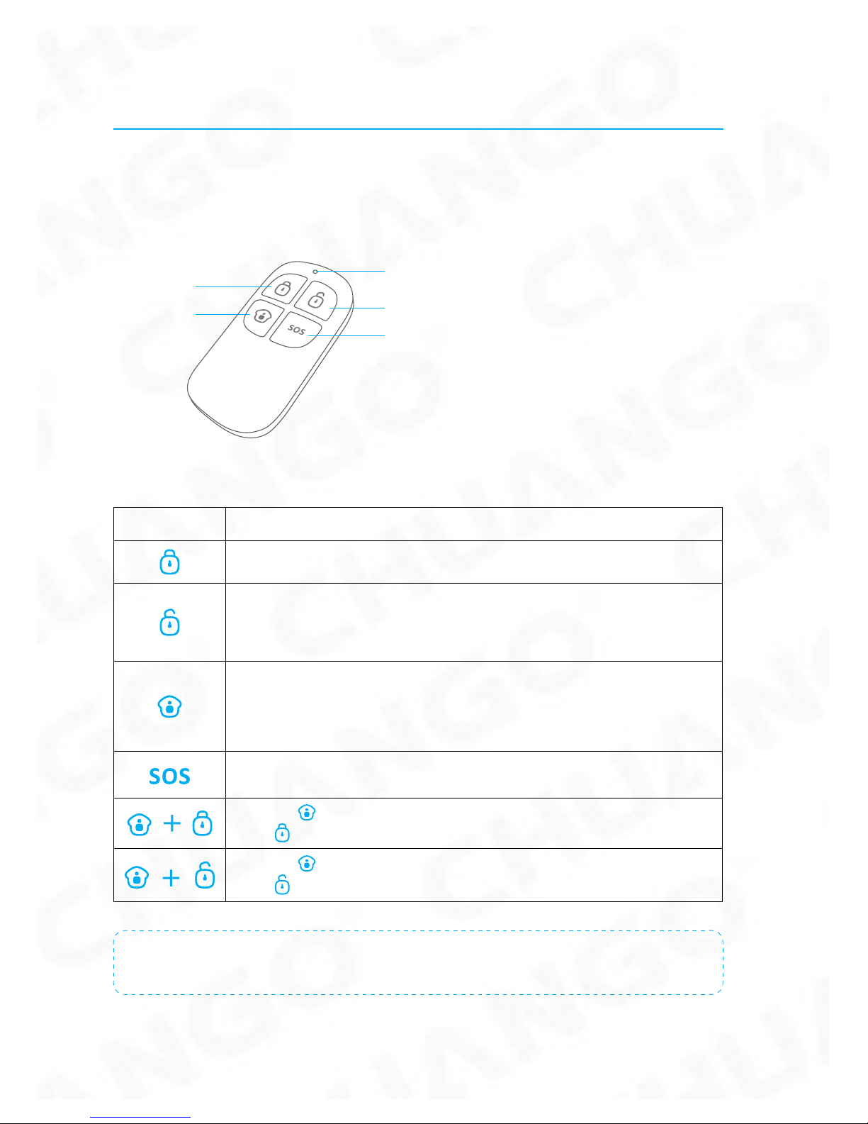
The Remote Control can be used to arm, part arm or disarm the system, and trigger
an emergency alarm (SOS).
Status Indicator
Disarm
Arm
Home Arm
(Part Arm)
SOS Button
Button System Status
All Sensors will be Armed. This mode is for use when the property is unoccupied.
The System will be Disarmed, no Sensors will be triggered.
Note: When set to ‘Disarm’, Fire, Smoke, and Gas Leakage Sensors (need to
purchase separately) will remain active as they are factory set to Instant Alarm
Zone
Sensors which are set to the Inactivated Zone will not be Armed. All other
Sensors will be Armed. This mode allows for selected Sensors (for example,
front/back door(s) to be Armed, allowing the occupier freedom of movement
within the property.
The SOS Button will trigger an ‘emergency’ alert notication to registered users
regardless of the Hub mode.
Press the [ ] button. After the indicator on the remote control blinks once,
press [ ] button within 3 seconds to mutely arm the system.
Press the [ ] button. After the indicator on the Remote Control blinks once,
press [ ] button within 3 seconds to mutely disarm the system.
Note: To turn off the Arm/Disarm tone permanently, open the App, go to "Settings"-"My Hub"-
"Arm / Disarm beep(s)".
Page 8
5
Door/ Window Contact
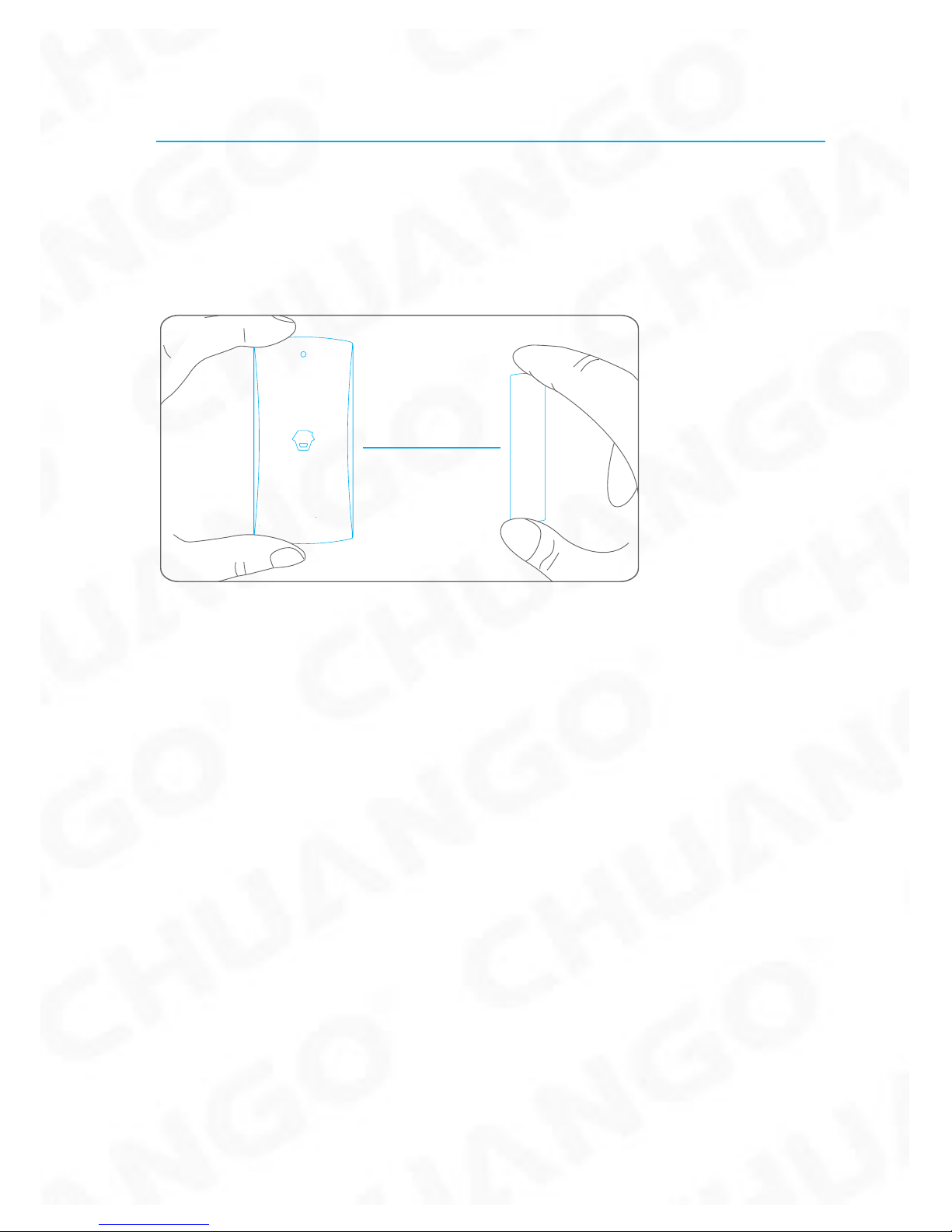
Door/ Window Contacts are set to ‘Normal Zone’ by default and are ideal for
protecting entry/exit points such as front and back doors and windows. When the
system is Armed, should a Door Contact be triggered (Magnet separated from the
Transmitter), a push notication showing the named Sensor will automatically be
sent to the registered users and the Hub Internal Siren will sound immediately.
Triggers
when > 1cm
LED blinks once
Tamper Switch
The Tamper Switch (small black button underneath the back cover) will activate an
alarm condition if an unauthorized attempt is made to remove the Contact from its
installed location.
Low Battery Indication
If the LED indicator ashes once per 3 second, the battery must be replaced.
Page 9
6
Pet-immune PIR Motion Dectector
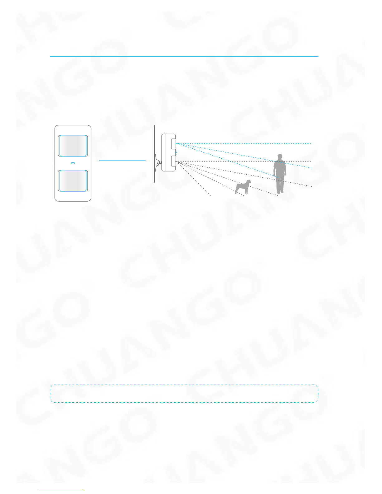
The Motion Contact is designed for use on interior walls and is set to Home Mode
by default. Whenever the Contact detects movement (while the alarm is armed) you
will receive a push alert notication showing the name of the Contact that has been
triggered and the Hub Internal Siren will sound immediately.
LED flashes once
when movement
is detected
Tamper Switch
The Tamper Switch (a black button with a silver spring at the top, located inside this
Contact) is used to indicate an unauthorized attempt to remove its cover.
Whenever this button is released, it will trigger an alarm and the push alert will
notify you which Contact has been triggered on tamper.
Low Battery Indication
If the LED indicator blinks once per 3 second, the battery must be replaced.
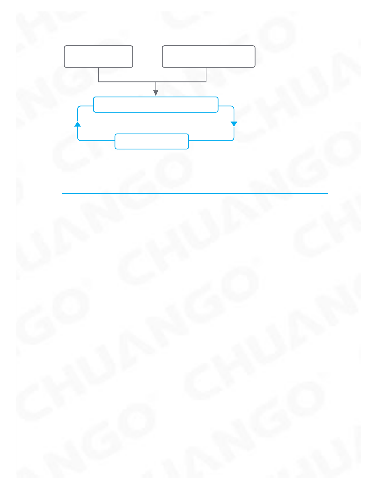
Working Mode
Test Mode
The Contact enters a 1 minute settling down period on power up, thereafter
entering into Test Mode. In Test Mode, the sensor detects movement every 10
seconds and emits an alarm signal every time movement is detected. Test Mode will
remain active for 3 minutes, thereafter entering into Power Saving Mode.
Note: You may also enter Test Mode by pressing the Test Button at the back of the Sensor.
Power Saving Mode (Sleep Mode)
If the Contact detects movement twice within 3 minutes the Contact will
automatically enter into Sleep Mode and no movement will be detected. The
Contact will leave Sleep Mode after a 3 minute period without any movement.
Page 10
7
Sleep after detecting human movement twice.
Case 1:
Initial start and then arm.
3 minutes later
No human movement within 3 minutes
Switch from sleep to arm.
Case 2:
Press the test button and then arm.
Pairing New Accessories to the Hub
There are two ways of pairing Accessories to the Hub – manually and via App.
Manual Pairing
To pair Accessories manually please follow the instructions below:
Remote Control and Sensors:
1. Press the Learn button at the back of the Hub
2. Press any button on the Remote Control or trigger the Sensor
Please note that pressing the Tamper Switch instead of triggering the Sensor will
register it as a 24 Hour Zone.
(Optional Accessory) Wireless Siren:
1. Press the Learn Button on the Siren
2. Arm the Hub via the App
Pairing from the App
To pair the Accessories via App, open the WiFi Alarm App, go to ‘Accessory Setting’
and follow the instructions on the screen.
Page 11
8
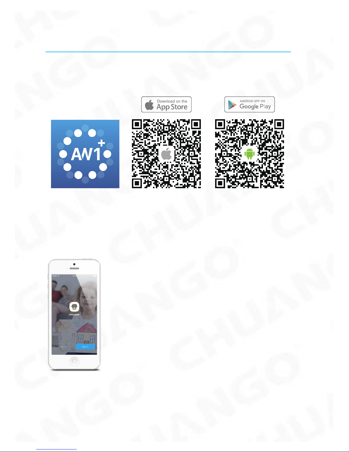
Getting Started
Step One: Download the App
Step Two: Sign Up / In
Press the "Sign up" button on the page, and follow the instructions to create your
account rst.
Once you have an account, select the "Sign in" button to enter the operation page.
Page 12
9
Step Three: Connect the Hub to Your Router
Power on the Hub, then follow the conguration steps on App to set up your Hub
with your home WiFi. Once the connection is nished, the Hub will beep once, wait
until the WiFi indicator and the Status indicator stop blinking, you are ready to operate your alarm system.
Important: AW1 Plus does not support WiFi of 5GHz band, If dual-band (5GHz and
2.4GHz) router is used, make sure to connect with the 2.4GHz WiFi instead of the
5GHz's. Make sure your smartphone is connected to the local WiFi network and
then follow the steps in the App to connect the AW1 Plus Hub to the router.
Note: If the connection was failed, please consult to FAQ in page 20 or contact our technical
support.
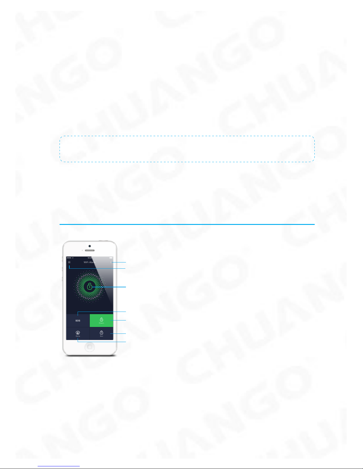
APP Control and Settings
Important Notice
In order to control the system remotely (WiFi/App), the Hub must be ‘mains’ powered via the Power Adapter. WiFi accessibility is disabled when the Hub Power
Adapter is unplugged from the mains power supply and running on batteries.
History & Setting
SOS
Account Management
System Status
Arm
Disarm
Home Arm (Part Arm)
Page 13
10
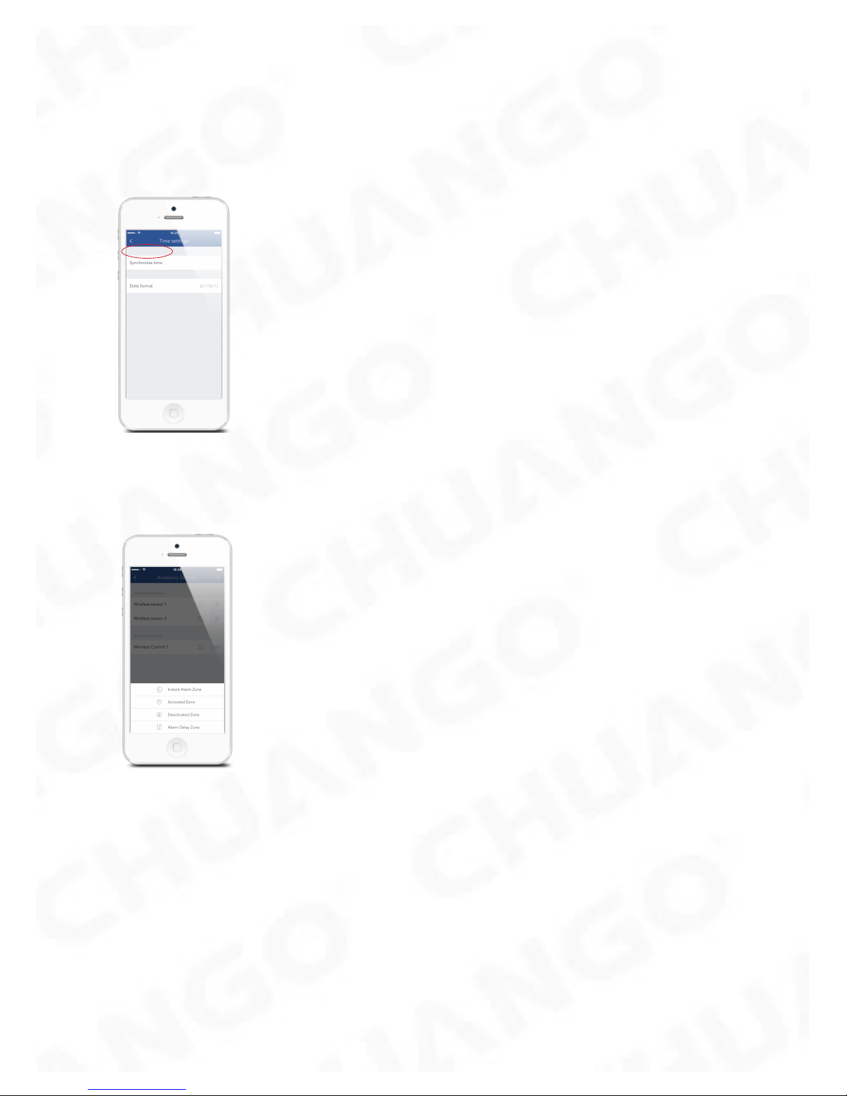
Synchronize Time (Important Setting)
The time shown on your mobile device must be synchronized with the time shown
on the Server prior to setup. Operation history will only be recorded correctly once
synchronization is complete.
Edit Accessories
Rename, add, delete and change the Zone Mode of each Sensor.
Activated Zone : Sensors set to Activated Zone are armed whether the alarm is in
Arm (Full Arm) or Home Arm (Part Arm) Mode. We recommend setting Window/
Door Sensors to Activated Zone.
Deactivated Zone : Sensors set to Inactivated Zone are only armed in Arm (Full
Arm) Mode. If Home Mode (Part Arm) is used, these Sensors are not armed and will
not activate the alarm on trigger. We recommend setting PIR Motion Sensors to
Inactivated Zone.
Instant Alarm Zone : Sensors set to Instant Alarm zone will activate the alarm when
triggered, regardless of the alarm status at the time (armed or disarmed).
Alarm Delay Zone : Sensors set to Alarm Delay Zone will sound the alarm after the
delay time passed.
Page 14
11
Note: Optional Smoke, Gas Leakage or Water Flood Sensors are automatically registered as
Instant Alarm Zone Sensors and cannot be changed to other Zone. Any Motion or Door/
Window Sensor paired to the Hub by pressing the Tamper Switch will also register as a Instant
Alarm Zone Sensor. A Instant Alarm Zone Sensor will activate the alarm when triggered,
regardless of the alarm status at the time (armed or disarmed).”
Internal Siren
The volume level, alarm duration, and arm/disarm beep can be adjusted in the App.
Wireless Siren
When connecting an Outdoor Siren (optional accessory) to the Hub, it can be
enabled/ disabled by switching the Alarm option to on/off. The on/off arm/disarm
beep and alarm duration can also be adjusted.
Delay Settings
Exit Delay Time
Set a time delay for you to leave your property without triggering an alarm.
Entry Delay Time (Available only for Alarm Delay Zone Sensor)
Set a time delay for you to enter your property without triggering an alarm.
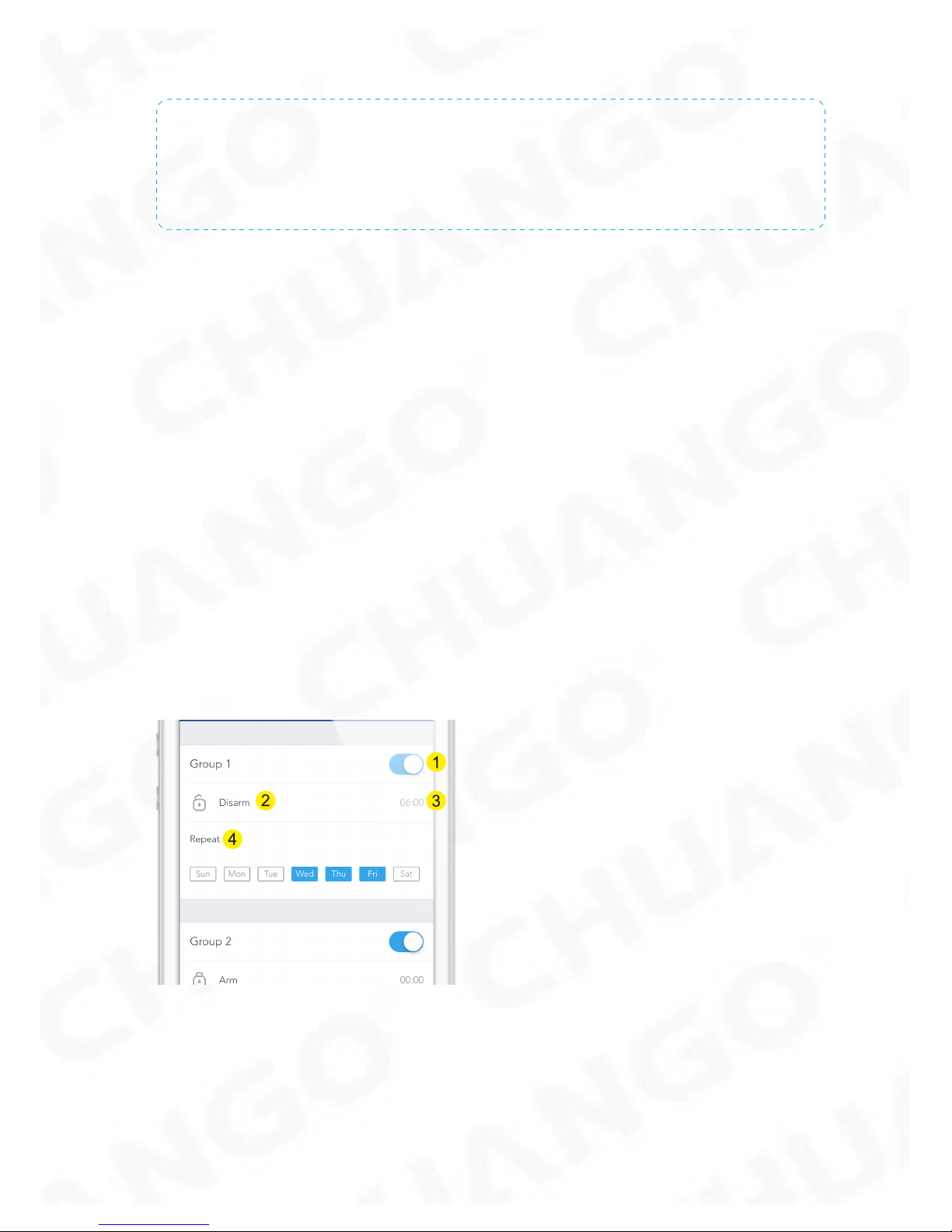
Timed Arm/Disarm
The system can be programmed to automatically Arm and Disarm the alarm at
predened times by following the steps below:
1. Slide the switch to the "on" position to activate the setting.
2. Choose any status you want the system to become (Arm / Disarm / Home Arm).
3. Choose the activate time of the status.
4. Tap the date that you want this Timed Group repeat.
Page 15
12
Ringtone of Push Alert
The selected ringtone will be heard when a Push Alert is received.
History
The Event Log holds a record of up to 300 events.
Account Management
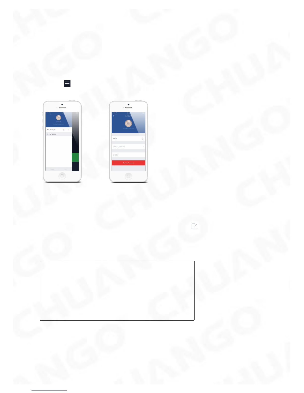
Tap the [ ] icon on the top left of the main page, click the portrait to enter the
account management.
Once you enter this page on the right side, you can edit the account as you want.
Tap on the picture, and you can add or replace your account image by taking a
picture or choosing a picture from your phone’s album.
If you want to change your account name, just tap on the [ ] button and enter a
new name.
Changing your password or deleting* your account with us (we will be sorry to see
you go, though) can also be done on this page.
Very Important
*Please note that when you delete your account, you will:
1. Delete all device(s)
2. Clear all personal information
3. Clear all shared settings
Page 16
13
Adding More Devices
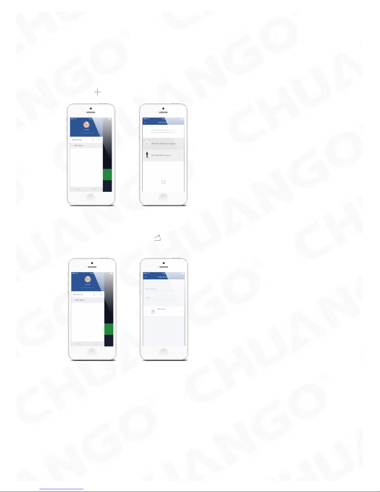
One account can achieve operating multiple devices in this App, if you have
multiple AW1 Plus Hubs or cameras, it is easy for you to manage these devices
within this App.
Tap the [ ] icon, you can add the device you want.
Sharing Devices
By pressing the share icon [ ] on this page, you can share access to your
device(s) with other registered accounts. Maximum 5 accounts can be shared to.
The user who receives the shared device(s) can arm/disarm the system, receive
alarm notications, view camera(s) in real time (if extra camera has been paired and
shared) but cannot re-share the device to other users or change the setting of the
device(s).
It is highly recommended that you set access limits to those who you may share
your device(s) with. In choosing not to do so, you grant your family and/or friends
continual access to the device(s) you have shared.
Page 17
14
Interference Resistance
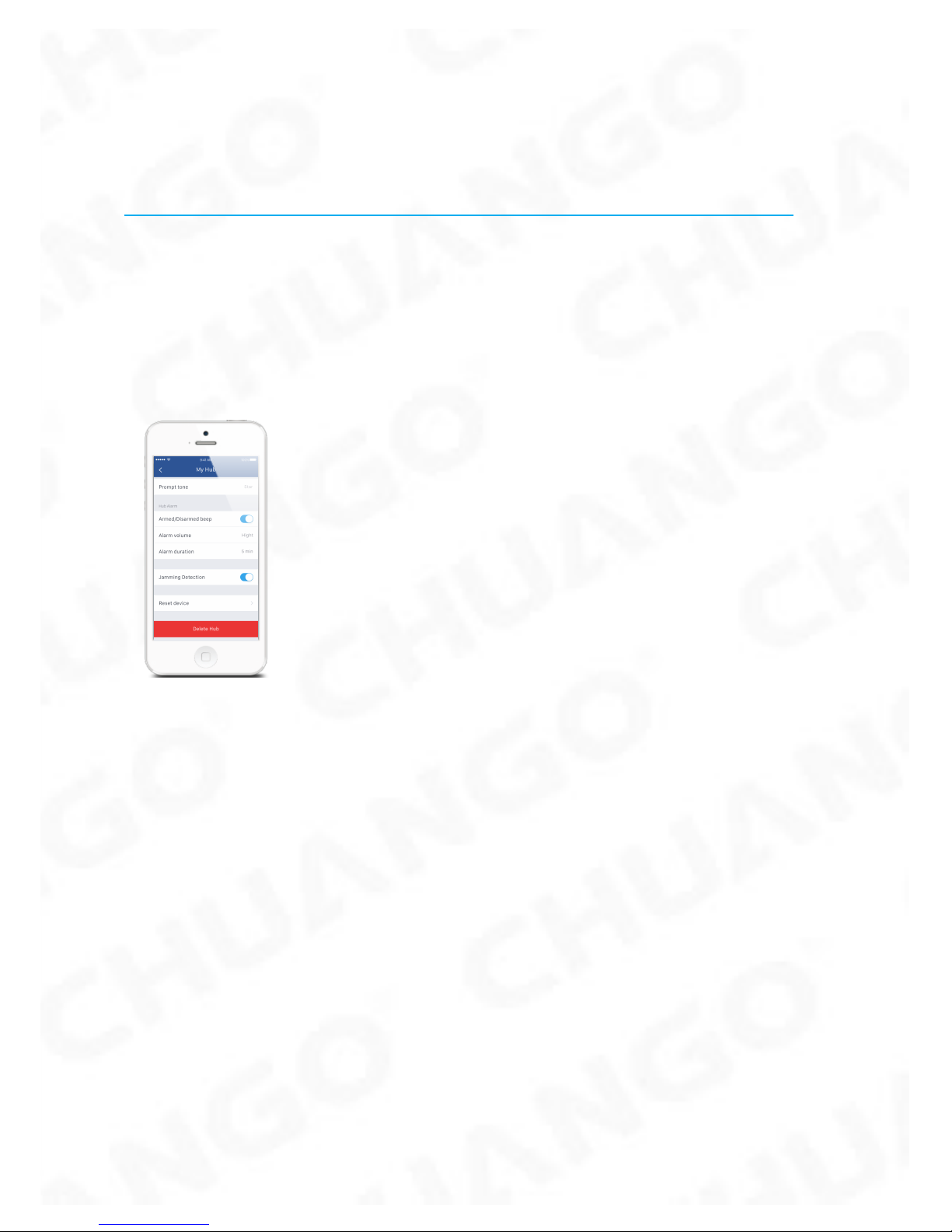
The AW1 Plus Hub has a feature of Interference Resistance. If this feature is enabled,
an alarm will be triggered if the radio channel is jammed continuously for more
than 30 seconds or the system is jammed for more than 3 periods of 10 seconds in
5 minutes period. The built-in siren will sound rapid beeps as a
pre-alarm warning 10 seconds before a full alarm occurs. The function is switched
off in default.
Page 18
15
Installation
Hub
Wall Mounting
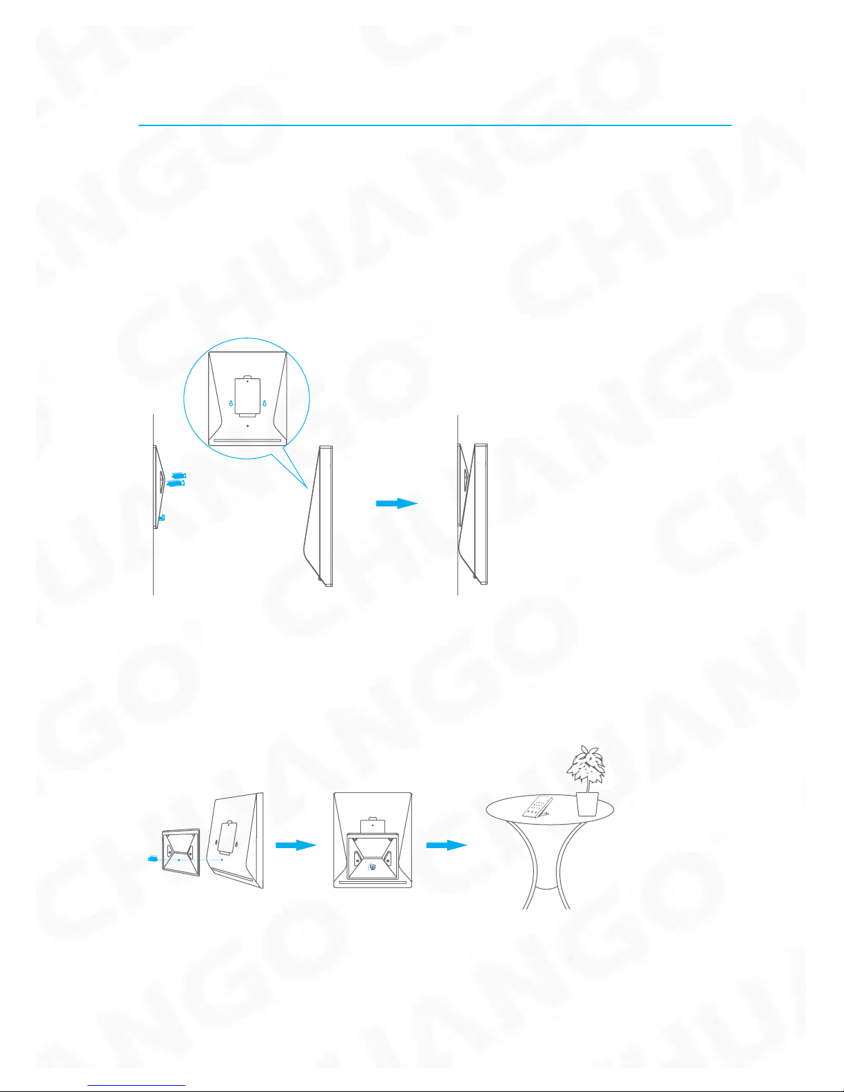
The Hub can be wall mounted using the Wall Bracket provided.
Using the screws supplied, mount the Wall Bracket onto the wall (ensuring that the arrow
on the bracket is pointing upwards), then match-up the Wall Bracket hooks to the holes
at the back of the Hub, and slide the Hub down onto the Wall Bracket.
①
Free-standing
The Wall Bracket can also be used as a tabletop stand.
Turn the Wall Bracket upside down so that the arrow is pointing downwards, and
align the screw hole underneath the Hub Battery Cover with the screw hole on the
Wall Bracket. Use the remaining screw to secure in place.
Warning :
A weak WiFi signal can seriously affect the performance of this Security Alarm
System. Please make sure that the Hub is located as close as possible to the main
Router for optimal connectivity.
Page 19
16
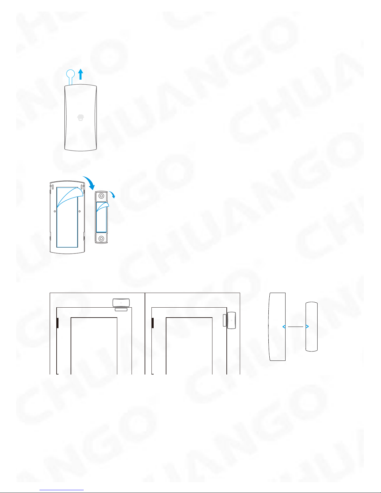
Door/ Window Contact :
Step 1: To power up the Contact, remove the Battery Tab
Step 2: Attach the Adhesive Pads to the back of the Transmitter and Magnet
Step 3: Place the Contact on the door/ window frame and the magnet on the door/
window ensuring that the distance between them is not greater than 1cm when the
door/ window is shut.
<1cm
Horizontal orientation Vertical orientation
Page 20
17
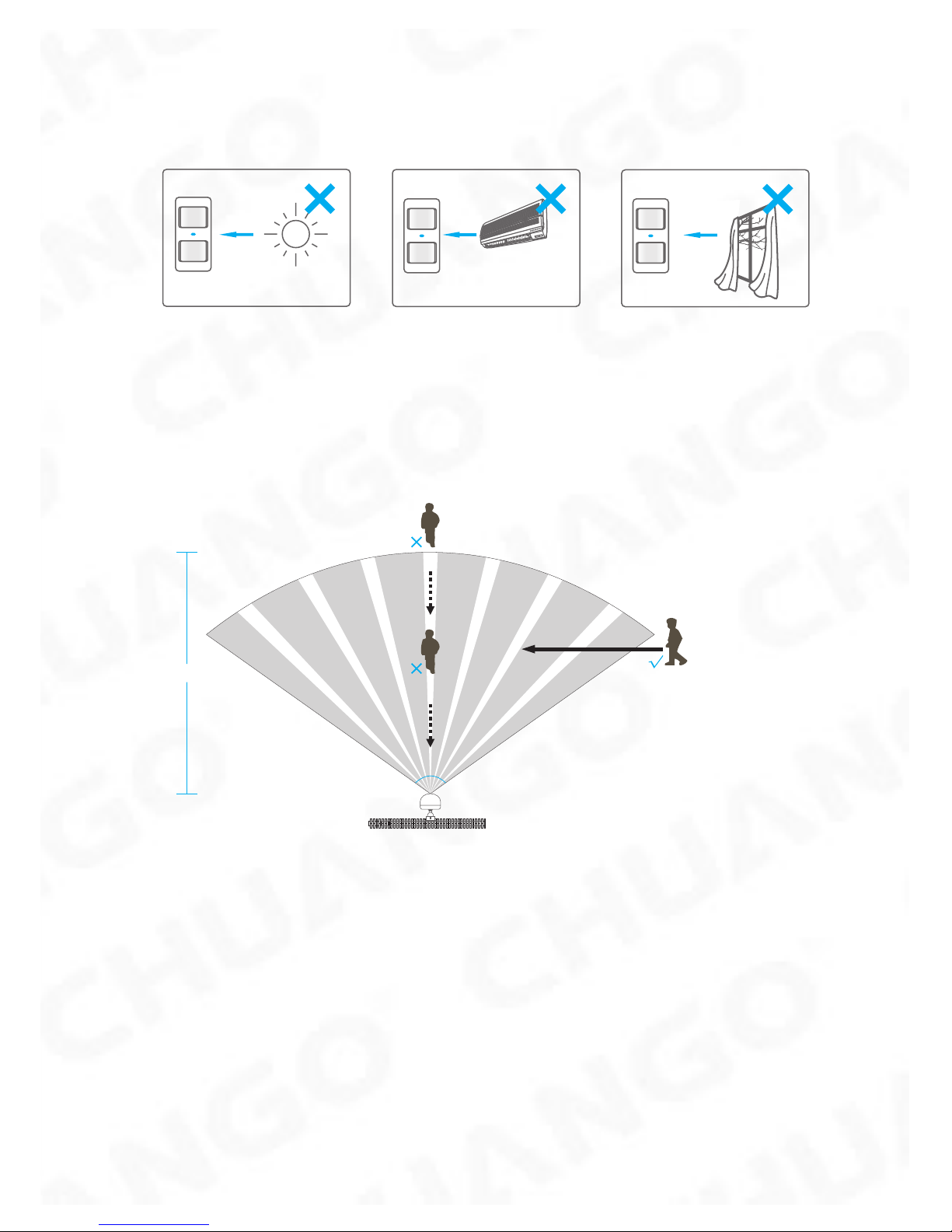
PIR Motion Detector :
Warning - Do not install
O
N
Facing direct sunlight
Near air conditioning/ heat
sources
Facing moving objects
Direction of motion and Detection Range
8m Max.
110°
It is easier to detect objects that move sideways in front of the Detector, but more
difcult to detect objects that move directly toward the Detector.
Page 21
18
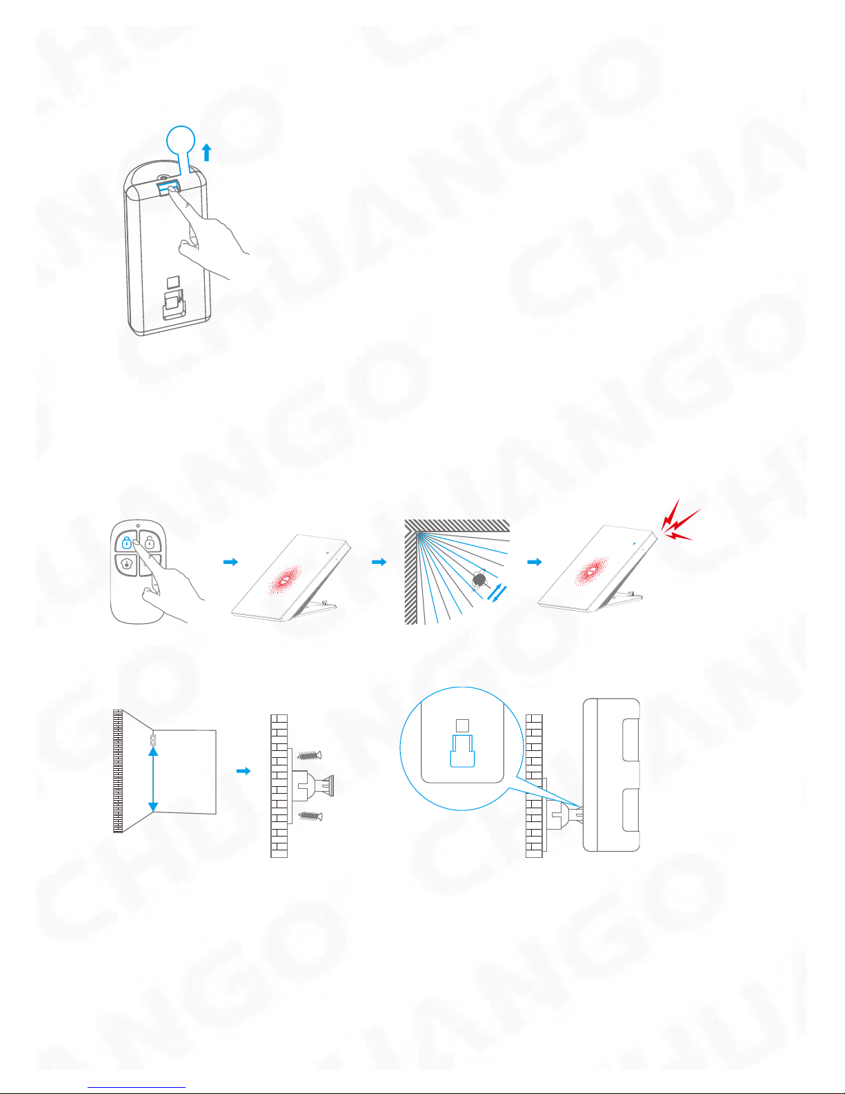
Step 1: To power up the Detector, remove the Battery Tab
Step 2: Perform a Walk Test
Press the Test Mode button at the back of the sensor to put it in Test Mode.
Place the Sensor in your desired location (don’t use screws at this point), arm the
system and walk sideways in front of the Sensor to test that the Detector triggers
the alarm.
Step 3: Install the Detector
2-2.2m
Ground
Parallel to the wall
Page 22
19
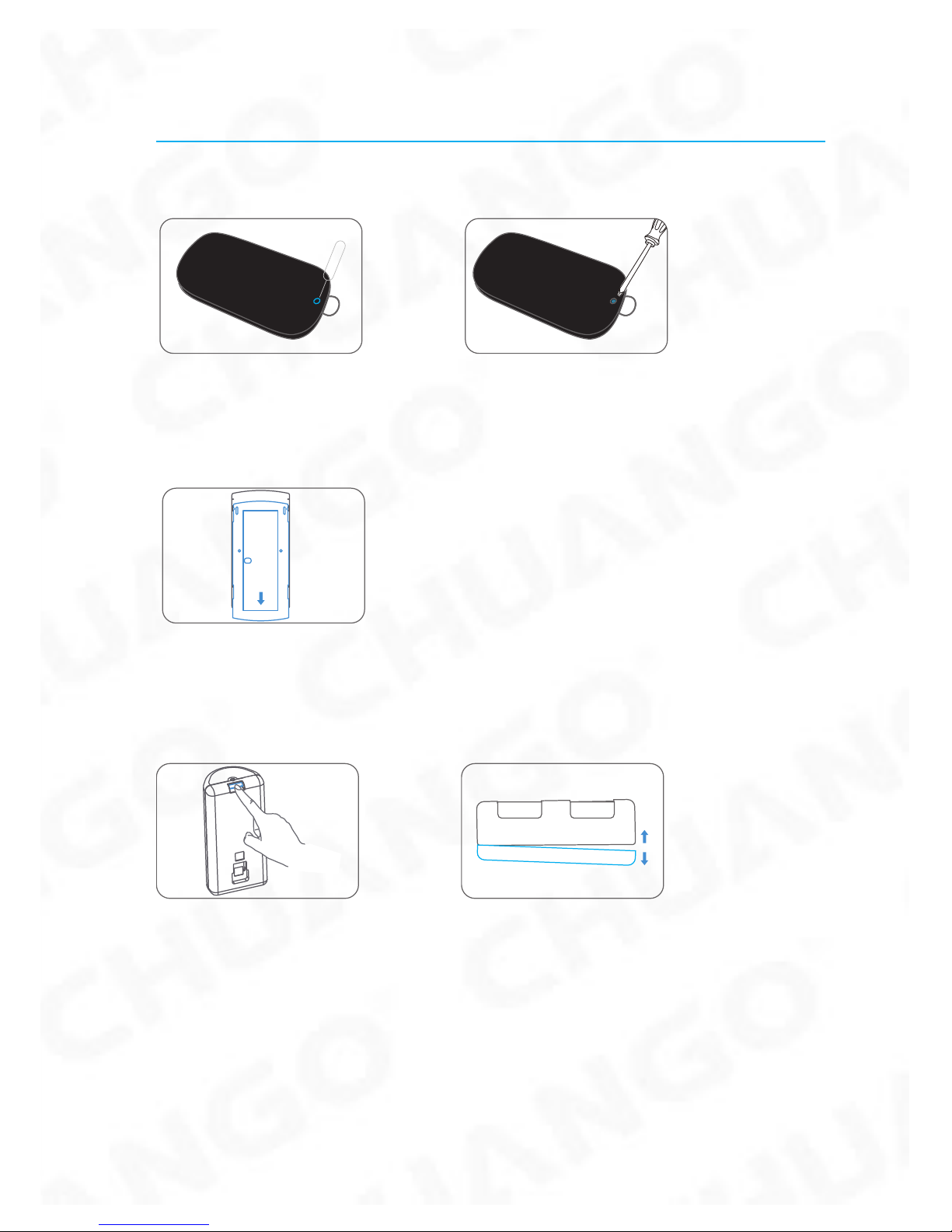
Replacing Accessory Batteries
Remote Control
Remove the screw Open the casing
Door/Window Contact
Open the casing
PIR Motion Detector
Remove the screw Open the casing
Page 23

20
FAQ
Failed to connect to the WiFi
Check whether the WiFi Indicator on the Hub has stopped ashing
If the WiFi Indicator stops ashing and the Hub cannot be controlled from the App,
please make sure that your local WiFi network is available and working properly.
Check that the WiFi name and password are correct.
Connect to a 2.4G WiFi network instead of 5G
Check that the Power Adapter is connected to the Hub.
Re-linking the Hub to the Router again by following the steps on App
The WiFi indicator and the status indicator are on, but I can’t control the alarm by
App
Check that your smartphone is connected to a WiFi network.
Wait a few minutes to see if the WiFi indicator and the status indicator start
ashing. If they do, your local WiFi network is not stable. Make sure that the Hub
is located in an area with good WiFi coverage and then re-pair with your local WiFi
network.
No response from the Hub when a Sensor is triggered
The Sensor is not within range of the Hub.
Check that the Sensor has been successfully paired to the Hub: Press any Button on
the Remote Control, arm the system and separate the transmitter from the Magnet
or press the Test Button on the Motion Detector. You can re-pair the Sensor to the
Hub by following the instructions in the App – [Accessory Setting].
I can’t Arm or Home Arm (Part Arm) my alarm by App
If the alarm has been triggered and hasn’t been disarmed and any Arm or Home
Arm operations will be refused to respond. In event of Operation Failure rst disarm
the system and then try again.
Page 24

21
How to delete an Accessory
You can delete any Sensor in the App by going to [Accessory Setting] ,slide the
sensor to the left and tap the delete icon to delete the sensor.
To delete all accessories press and hold the [Learn] button inside the Hub for 5
seconds, the Hub will beep once to indicate that all accessories have been deleted.
No sound when alarming
Check that the Hub Alarm volume is not set to mute and the ring time is not set to ‘0’.
Adjust the volume and the ring time accordingly.
How to reset the alarm system
Click the [WiFi] button for 3 times, then press and hold it for 3 seconds, a long beep
would be heard to indicate the reset is completed.
All the settings have been restored to the default conditions.
Please note that this process does not delete any Sensors.
Page 25

22
Specications
Hub
Power Supply DC 12V 500 mA
Battery 3.7V 600 mAh Li-ion x 1pc
Battery Life Recharge Cycle 300 times
WiFi IEEE 802.11b/g/n
Standby Current <50mA
Alarm Current <90 mA
Internal Siren 90 dB
Optional Accessories 10 Remote Controls, 50 Sensors
Radio Frequency 315MHz or 433.92MHz
Housing Material ABS Plastic
Operating Condition
Temperature 0°C~+55°C
Relative Humidity <80% (non-condensing)
Hub Dimensions 125 x 150 x 30 mm (L x W x H)
Bracket Dimensions 87.5 x 81.5 x 12 mm (L x W x H)
Remote Control
Power Supply DC 3V (CR2025 lithium battery x 1pc)
Transmit Current <7 mA
Transmitting Distance <80 m (open area/no interference)
Radio Frequency 315MHz or 433.92 MHz
Housing Material ABS Plastic
Operating Condition
Temperature 0°C~+55°C
Relative Humidity <80% (non-condensing)
Dimensions 58 x 31 x 9.5 mm (L x W x H)
Page 26

23
Door/ Window Contact
Power Supply DC 1.5V (1.5V AA LR6 battery x 1pc)
Static Current <35 uA
Alarm Current <40 mA
Transmitting Distance <80 m (open area/no interference)
Radio Frequency 315MHz or 433.92 MHz
Housing Material ABS Plastic
Operating Condition
Temperature 0°C~+55°C
Relative Humidity <80% (non-condensing)
Transmitter Dimensions 71 x 34 x 17.5 mm (L x W x H)
Magnet Dimensions 51 x 12 x 13.5 mm (L x W x H)
Pet-immune PIR Motion Detector
Power Supply DC 3V (1.5V AA LR6 battery x 2pcs)
Static Current <13 uA
Alarm Current <20 mA
Detection Scope 8m/110°
Pet Immunity <25kgs
Transmitting Distance <80 m (open area/no interference)
Radio Frequency 315MHz or 433.92 MHz
Housing Material ABS Plastic
Operation Condition
Temperature 0°C~+55°C
Relative Humidity <80% (non-condensing)
Detector Dimensions 108 x 52 x 36.8 mm (L x W x H)
Bracket Dimensions 52 x 30 x 26.5 mm (L x W x H)
Page 27

Printed in China
PA : AW1 Plus-UM-EN-V1.0
© 2017 Chuango. All Rights Reserved.
 Loading...