

Page 1

6121 Baker Road,
Suite 108
Minnetonka, MN 55345
www.chtechnology.com
Phone (952) 933-6190
Fax (952) 933-6223
1-800-274-4284
Thank you for downloading this document from C&H Technology, Inc.
Please contact the C&H Technology team for the following questions -
Technical
Application
Assembly
Availability
Pricing
Phone – 1-800-274-4284
E-Mail – sales@chtechnology.com
www.chtechnology.com - SPECIALISTS IN POWER ELECTRONIC COMPONENTS AND ASSEMBLIES - www.chtechnology.com
Page 2
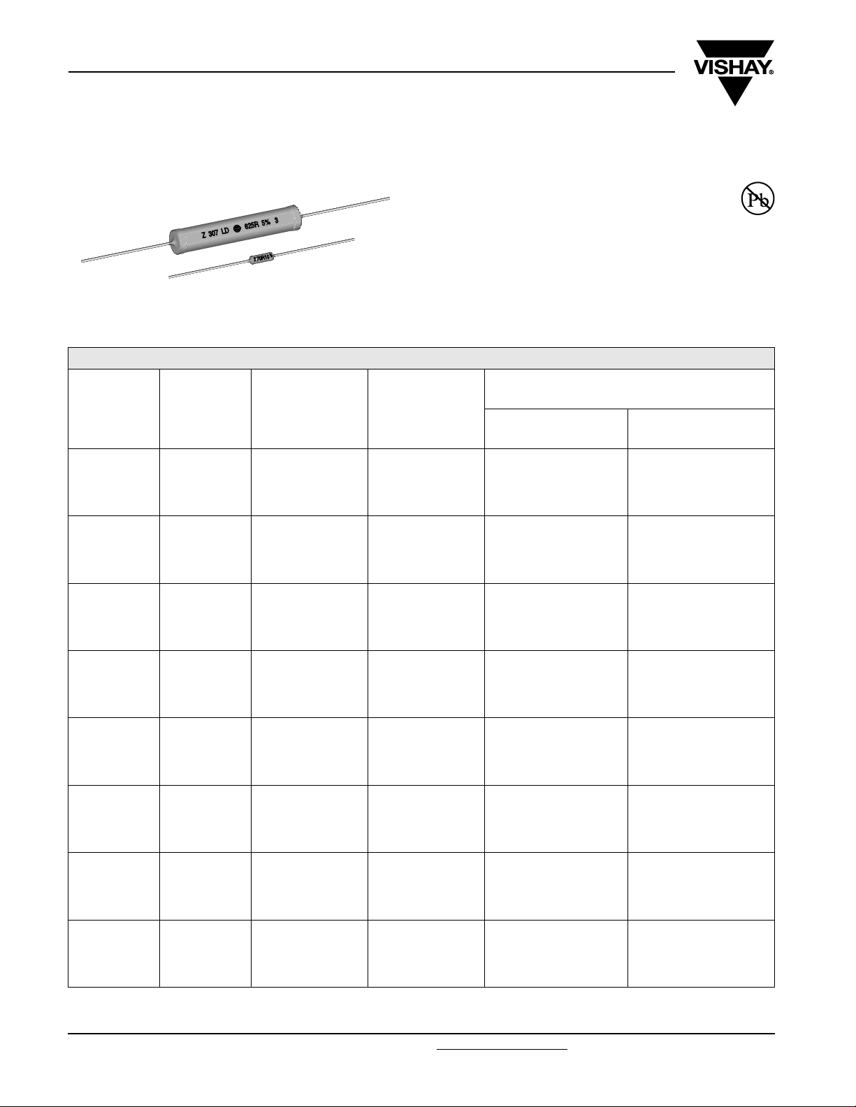
Z300
Vishay Draloric
Axial Cemented Wirewound Resistors
STANDARD ELECTRICAL SPECIFICATIONS
GLOBAL
MODEL
Z310309 Z301 1
ZDA0411 ZDA0411 2
ZDV0411 ZDV0411 2
Z320414 Z302 3
Z330617 Z303 4
Z350922 Z305 6
Z360933 Z306 8
Z370947 Z307 10
1)
Lower TCR or other power range on request
HISTORICAL
MODEL
POWER RATING
P
40 °C
W
FEATURES
• All welded construction
• Non flammable cement coating
• Ceramic core
• Various kinds of lead forming available
• Lead (Pb)-free
TOLERANCE
± %
10
5
2
1
10
5
2
1
10
5
2
1
10
5
2
1
10
5
2
1
10
5
2
1
10
5
2
1
10
5
2
1
RESISTANCE RANGE E12/E24
WM 50 (Class 1)
TCR -10...-80 ppm/K
R30 - 270R
R30 - 270R
-
-
R47 - 560R
R47 - 560R
on request
on request
R47 - 560R
R47 - 560R
on request
on request
R10 - 510R
R10 - 510R
R22 - 510R
1R0 - 510R
R10 - 1K0
R10 - 1K0
R10 - 1K0
1R0 - 1K0
R10 - 2K4
R10 - 2K4
R62 - 2K4
R62 - 2K4
R13 - 4K7
R13 - 4K7
1R0 - 4K7
2R2 - 4K7
R20 - 8K2
R20 - 8K2
1R8 - 8K2
3R3 - 8K2
1)
Ω
WM 110 (Class 3)
TCR 100...180 ppm/K
R68 - 2K0
R68 - 2K0
-
-
1R5 - 4K3
1R5 - 4K3
-
-
1R5 - 4K3
1R5 - 4K3
-
-
1R8 - 3K3
24R - 3K3
-
-
1R8 - 3K9
12R - 3K9
-
-
3R9 - 10K
10R - 10K
-
-
6R8 - 16K
6R8 - 16K
-
-
12R - 30K
12R - 30K
-
-
www.vishay.com For technical questions, contact: ww1resistors@vishay.com
106 Revision: 17-Apr-07
Document Number: 21007
Page 3

Z300
Axial Cemented Wirewound Resistors
Vishay Draloric
GLOBAL PART NUMBER INFORMATION
New Global Part Numbering: Z32041411509K2C000 (preferred part numbering format)
Z3 204141 1509K2C000
MODEL PACKAGINGTOLERANCE CODE
(see Standard
Electrical
Specifications table)
Historical Part Number example: Z32041411509K2C000 15 Ω 10 % WM50, ammo 53 mm, 500 pc (will continue to be accepted)
Z302
HISTORICAL MODEL TC / MATERIAL VALUE TOLERANCE CODE PACKAGING
TC/MATERIAL
1 =
-10...- 80 ppm/K
WM50
Class 1
3 =
100...180 ppm/K
WM110
Class 3
4 = SWI
(special
winding)
VALUE
3 digit value
1 digit multiplier
Multiplier:
F = *10
7 = *10
8 = *10
9 = *10
0 = *10
1 = *10
2 = *10
3
F = ± 1.0 %
G = ± 2.0 %
-4
-3
-2
-1
0
1
2
J = ± 5.0 %
K = ± 10.0 %
15 Ω 10 % AC
(see Packaging table)
The 5 digit BV number will
SPECIAL
be encoded using a 36
character code. This code
contains numbers 0...9
and letters A...Z (36
characters total and allows
to encode at least 46.655
five digit BV numbers.
000 = standard
PACKAGING TABLE
SAP
DRALORIC
LEGACY
21 A1 G53 Ammo pack tape 53 mm, 1000 pcs. Z301
DS RS G53 Reel pack tape 53 mm, 7500 pcs. Z301, Z302
D2 R2 G53 Reel pack tape 53 mm, 2000 pcs. Z301, Z302
6C AC G83 Ammo pack tape 83 mm, 500 pcs. Z302, Z303
H1 R1 G83 Reel pack tape 83 mm, 1000 pcs. Z302, Z303
2C AC G53 Ammo pack tape 53 mm, 500 pcs. Z302, Z303
JS RS 108 Reel pack tape 108 mm, 7500 pcs. Z302
HS RS G83 Reel pack tape 83 mm, 7500 pcs. Z302
4C AC G73 Ammo pack tape 73 mm, 500 pcs. Z302
D1 R1 G53 Reel pack tape 53 mm, 1000 pcs. Z303
6B AB G83 Ammo pack tape 83 mm, 250 pcs. Z305, Z306
41 A1 G73 Ammo pack tape 73 mm, 1000 pcs. ZDA0411
F2 R2 G73 Reel pack tape 73 mm, 2000 pcs. ZDA0411
40 A2 G73 Ammo pack tape 73 mm, 2000 pcs. ZDV0411
HC RC G83 Reel pack tape 83 mm, 500 pcs. Z305, Z306
LC LC loose PKG, 500 pcs. Z302, Z303
LJ LJ loose PKG, 200 pcs. Z307
L1 L1 loose PKG, 1000 pcs. ZL302
24 A4 G53 Ammo pack tape 53 mm, 4000 pcs. Z302
6A A4 G83 Ammo pack tape 83 mm, 100 pcs. Z305
25 A4 G63 Ammo pack tape 63 mm, 4000 pcs. Z302
Document Number: 21007 For technical questions, contact: ww1resistors@vishay.com
Revision: 17-Apr-07 107
PACKAGING
2 digits
www.vishay.com
Page 4

Z300
Vishay Draloric
Axial Cemented Wirewound Resistors
DIMENSIONS
G
B
For packaging dimensions see appropriate catalog or web page.
MODEL
A
max
B
max
Z301 8.5 [0.355] 3 [0.118] 0.7 [0.027] 53 ± 1 [2.087 ± 0.039] 0.5
ZDA0411 11 [0.433] 4 [0.157] 0.7 [0.027] 53 ± 1 [2.087 ± 0.039 0.8
Z302 13 [0.512] 4.8 [0.189] 0.8 [0.031] 53 ± 1 [2.087 ± 0.039] 1.1
Z303 15.8 [0.622] 5.5 [0.217] 0.8 [0.031] 53 ± 1 [2.087 ± 0.039] 1.4
Z305 22.3 [0.878] 8.7 [0.343] 0.8 [0.031] 83 ± 1 [3.268 ± 0.039] 3.7
Z306 32.3 [1.272] 8.7 [0.343] 0.8 [0.031] 83 ± 1 [3.268 ± 0.039] 5
Z307 49.8 [1.961 9 [0.354] 0.8 [0.031] 120 ± 2 [4.724 ± 0.079] 7
A
C
DIMENSIONS in millimeters [inches]
C
max
GWeight (g)
DIMENSIONS ZDV0411
Δh
P
P
2
Ø 4 max.
“Z”
1 max.
H
1
H
0
H
L
P
1
d
F
P
0
W
2
W
W
0
1
D
0
t
For body dimensions, see dimensions table above, model ZDA0411.
Area “Z”
a
1
R
d
d
1
2
R
R
a
2
R
d1 / d2 = 35 ... 45°
/ a2 = < 1.25
a
1
1) Test over 10 holes - 9 intervals P0 12 × 9 = 114.3 ± 0.5
2) Parallelism, < 0.5 mm
3) Thickness of carrier tape: 0.55 mm ± 0.1
1
W
DIMENSIONS (in millimeters) TOL.
Lead Ø d 0.6
Pitch of components P 12.7 ± 1.0
Pitch of sprocket holes
Distance between hole
center and resistor center
Distance between hole
center and lead center
1)
P
0
P
1
P
2
12.7 ± 0.3
3.85 ± 0.7
6.35 ± 0.7
Lead spacing F 5 + 0.6, - 0.1
Angle of Insertion Δh1 2 max. -
Width of carrier tape W 18.0 + 1, - 0.5
Width of adhesive tape
Position of holes
Position of adhesive tape
W
0
W
1
W
2
12.0 ± 0.5
9 + 0.75, - 0.5
0.5 + 0, - 0.5
Body to hole center H 16.0 ± 0.5
Lead crimp to hole center
Hole Ø
Thickness of tape
3)
H
0
D
0
t 0.9 max. -
19.5 ± 1.0
4.0 ± 0.2
2)
Height of cutting L 11 max. -
Height of insertion
H
32.3 max. -
1
www.vishay.com For technical questions, contact: ww1resistors@vishay.com Document Number: 21007
108 Revision: 17-Apr-07
Page 5

Z300
120
100
80
60
40
RATED POWER IN %
20
0
- 55
Derating
300
200
Axial Cemented Wirewound Resistors
300
200
100
TEMPERATURE RISE IN °C
50
40
150 250 350
AMBIENT TEMPERATURE IN °C
0
0
0.4
Vishay Draloric
ZDA 1041
Z301
0.8 1.2
1.6
POWER IN W
2.0
Temperature Rise
300
Z302
Z303
Z305
200
Z306
Z307
100
TEMPERATURE RISE IN °C
0
0 1 2 3 4 5
POWER IN W
Temperature Rise
100
TEMPERATURE RISE IN °C
0
0
2
Temperature Rise
4
PERFORMANCE
TEST TEST RESULTS
Damp Heat, Steady State 56 days ± 3 % ΔR
Climatic Sequence ± 3 % ΔR
Load Life 5000 h ± 3 % ΔR
Short Time Overload, 5 x rated power x 5 sec ± 1 % ΔR
Vibration ± 1 % ΔR
Shock ± 1 % ΔR
Resistance to Soldering Heat ± 1 % ΔR
6 8
POWER IN W
10
Document Number: 21007 For technical questions, contact: ww1resistors@vishay.com
www.vishay.com
Revision: 17-Apr-07 109
 Loading...