

Page 1

6121 Baker Road,
Suite 108
Minnetonka, MN 55345
www.chtechnology.com
Phone (952) 933-6190
Fax (952) 933-6223
1-800-274-4284
Thank you for downloading this document from C&H Technology, Inc.
Please contact the C&H Technology team for the following questions -
Technical
Application
Assembly
Availability
Pricing
Phone – 1-800-274-4284
E-Mail – sales@chtechnology.com
www.chtechnology.com - SPECIALISTS IN POWER ELECTRONIC COMPONENTS AND ASSEMBLIES - www.chtechnology.com
Page 2
RWM
Vishay Sfernice
Enamelled Wirewound Power Resistors
Axial Leads
FEATURES
• High dissipation up to 30 W (25 °C)
• Fire Proof
• Excellent Endurance typical drift ± 1.5 % after
1000 h
• Conformal Vitreous Enamel
• All Welded Construction
• Low ohmic values 0.1 Ω available
• Termination: Sn/Ag/Cu
RoHS
COMPLIANT
As a result of more than 50 years of experience and
continuous improvements the RWM Series of resistors
features proven reliability in AC or DC applications.
The high quality of the RWM resides mainly in the use of a
proprietary VISHAY SFERNICE enamel fired at high
temperature and free from any compound liable to corrode
the resistive wire.
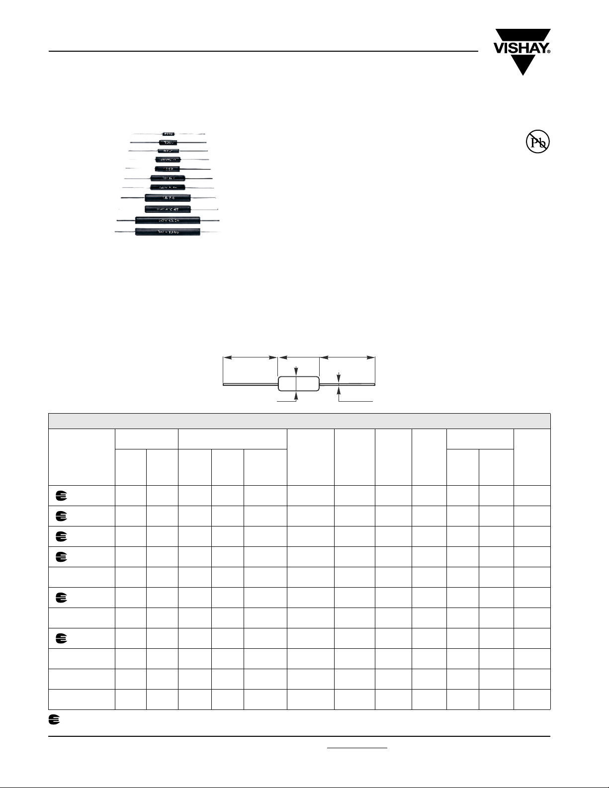
DIMENSIONS in millimeters
25 min. A 25 min.
TECHNICAL SPECIFICATIONS
DESIGNATIONS POWER RATING
VISHAY
SFERNICE
STYLES
RWM 4 x 10 RB59 JB 2.6 W 3 W 5.5 W
RWM 4 x 22 RB61 HB 4.5 W 5 W 7 W
RWM 5 x 26 RB57 - 6 W 7 W 10 W
RWM 6 x 22 RB57 KB 6 W 7 W 10 W
RWM 8 x 26 RB60 - 7 W 8 W 10 W
RWM 6 x 34 RB60 LB 7 W 8 W 12 W
RWM 8 x 34 RB58 - 9.5 W 11 W 14 W
RWM 8 x 45 RB58 MB 9.5 W 11 W 20 W
RWM 10 x 45 - - 21 W 25 W 25 W
RWM 10 x 64 - - 21 W 25 W 25 W
RWM 10 x 65 - - 25.8 W 30 W 30 W
Undergoes European Quality Insurance System (CECC)
CECC
40201
-001
CECC
40201
-002
at
+ 70 °C
at
+ 25 °C
With
Surface
Temp.
≤ + 450 °C
The performance of this series of professional resistors fully
meets the requirements of the following specifications:
– NF C 83-210-001
– CECC 40201-001
– BS - CECC 40201-002
Ø 0.8 ± 0.1 Ø B
Ohmic
Range in
Relation to
Tolerance
± 5 %
E24 Series
0.1 Ω
10 kΩ
0.1 Ω
16 kΩ
0.1 Ω
27 kΩ
0.1 Ω
39 kΩ
0.1 Ω
27 kΩ
0.33 Ω
36 kΩ
0.33 Ω
36 kΩ
0.47 Ω
62 kΩ
0.47 Ω
62 kΩ
0.68 Ω
100 kΩ
0.68 Ω
100 kΩ
Qualified
Ohmic
Range
NF C
83-210
0.1 Ω
10 kΩ
0.1 Ω
6.8 kΩ
0.15 Ω
10 kΩ
0.15 Ω
39 kΩ
0.33 Ω
15 kΩ
0.47 Ω
33 kΩ
Limiting
Element
Voltage
120 V 4.8 kΩ 12
300 V - 22.1
350 V 18.8 kΩ 24.7
350 V 17.5 kΩ 18
- 500 V - 24.7
500 V 31 kΩ 33.7
- 650 V - 33.7
650 V 38 kΩ 45.8
- 800 V 25.6 kΩ 45.8
- 800 V 25.6 kΩ 63.8
- 800 V 21.3 kΩ 63.8
Critical
Resis-
tance
DIMENSIONS
IN mm
A Ø B
± 1
5.5
± 1
5.5
± 1
7.4
± 1
6.5
± 1
7.4
± 1
7.4
± 1
7.4
± 2
9.4
± 2
9.4
± 1
9.4
± 1
9.4
± 1
± 1
± 1.5
± 1
± 1.5
± 1.5
± 1.5
± 1.5
± 1.5
± 1.5
± 1.5
WEIGH T
IN g
1
2
3
2.2
3
4
4
8
8
14
14
www.vishay.com For technical questions, contact: sfer@vishay.com Document Number: 50008
38 Revision: 11-Dec-06
Page 3
RWM
Enamelled Wirewound Power Rsistors
Vishay Sfernice
Axial Leads
PERFORMANCE
CECC 40201 - EN 140-201
TESTS CONDITIONS REQUIREMENTS
Short Time Overload
Temperature Cycling - 55 °C + 200 °C ± (1 % + 0.05 Ω) ± (0.5 % + 0.05 Ω)
Humidity (Steady State)
Terminal Strength
Load Life
10 Pr during 10 s
25 °C ambient
56 days
40 °C Ambient - R.H. 95 %
Tensile test: 20 N
2 successive bending
2 full rotations of 180°
1000 h at Pr
90/30 Cycle
25 °C ambient
± (2 % + 0.1 Ω) ± (0.5 % + 0.05 Ω)
± (5 % + 0.1 Ω) ± (0.5 % + 0.05 Ω)
± (1 % + 0.05 Ω) ± (0.1 % + 0.05 Ω)
± (5 % + 0.1 Ω) ± (1.5 % + 0.05 Ω)
OVERLOAD
Heavy overloads can be endured in the form of short pulses < 0.1 s. Particular requirements should be submitted to Vishay
Sfernice, specifying peak voltage, cycle and environmental conditions.
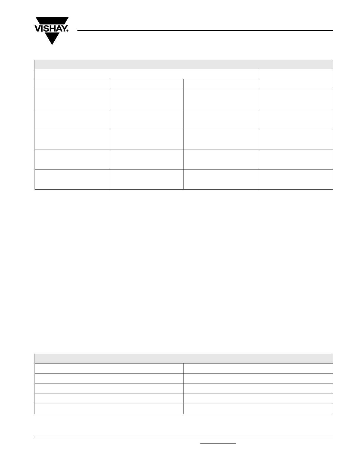
TYPICAL DRIFTS
RECOMMENDATIONS FOR USE
Since these components are high dissipation power resistors, customers are advised to use a high melting point solder.
For low ohmic values, the measurement becomes critical and the connecting wires resistance is to be included. The value is
measured at 5 mm from the resistor body.
Group Mounting
In a still atmosphere, a distance between axes equal to five times the resistor’s diameter is recommended.
Cabinet Mounting
• Unventilated box: dissipation should be reduced (see dimensional drawing).
• Forced ventilation: if conditions are appropriate, dissipation may be doubled or even trebled.
• In any case: the surface temperature at the hottest point should not exceed 450 °C.
These aspects should be considered by the end user.
ELECTRICAL SPECIFICATIONS
Tolerance Standard ± 5 %
On request ± 1 % to ± 10 %
Temperature Coefficient + 75 ppm/°C typical
Dielectric Withstanding Voltage NF EN 140000 500 VRMS - 1 minute - 10 mA
Inductance non inductive (Ayrton-Perry) winding available
Document Number: 50008 For technical questions, contact: sfer@vishay.com
Revision: 11-Dec-06 39
www.vishay.com
Page 4
RWM
Vishay Sfernice
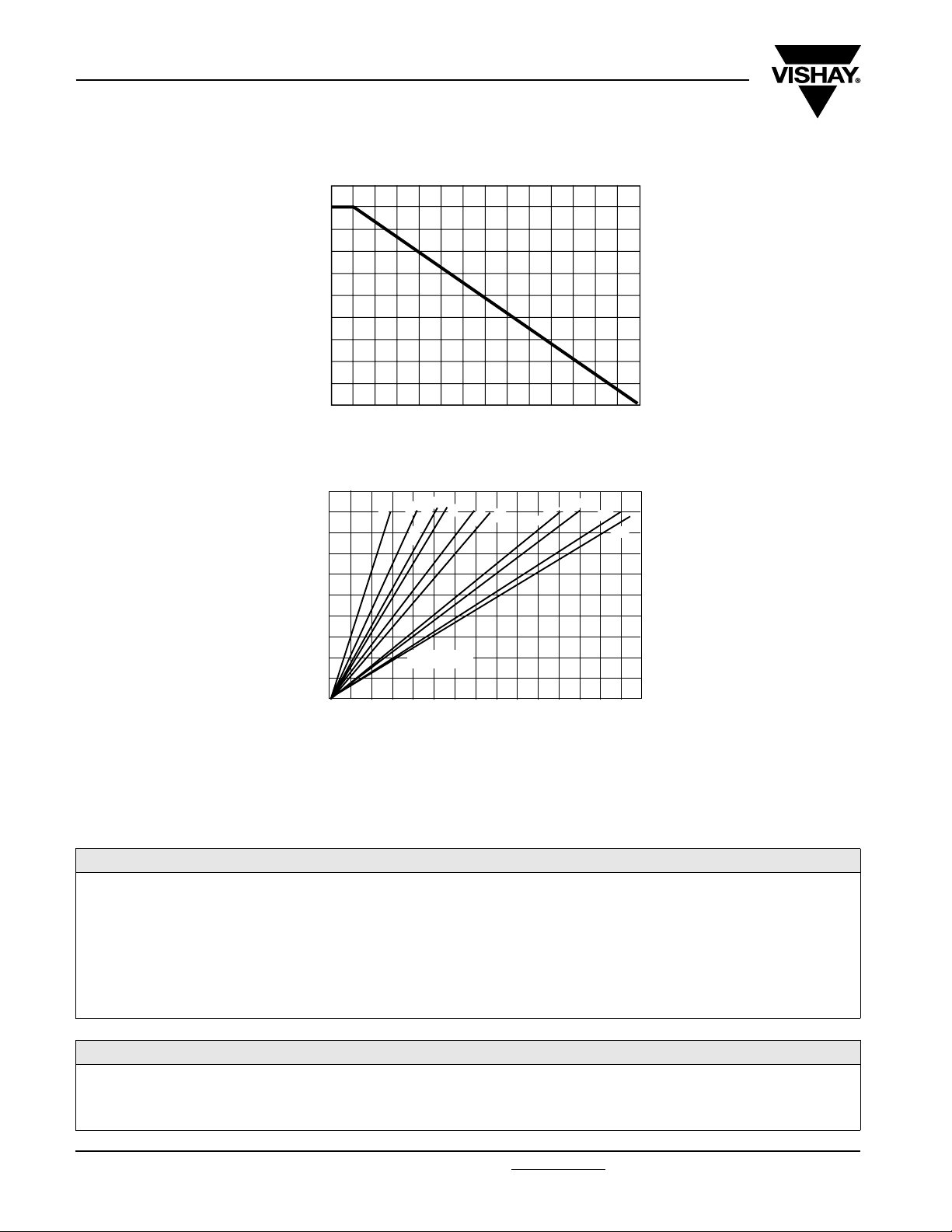
POWER RATING CHART
116
100
REWOP DETAR %
75
50
25
0
TYPICAL TEMPERATURE RISE
C ° N I E R
400
U
T
300
A R E P M E T
Enamelled Wirewound Power Resistors
Axial Leads
25 100 200 300 350
0
IENT TEMPERATURE IN °C
AMB
5 4
x
46 x
0 1
4 x 10
4 x 22
5 x 26 - 6 x 22
8 x 26
6 x 34
8 x 34
8 x 45
01
5
6 x
0 1
T O P S
200
T
O
H
100
0
0 2 4 6 8 10 12 14 16 18 20 22 24 26 28 30
Optional
RATED POWER IN WATTS
MARKING
Sfernice trademark, model and style, CECC style, if applicable (except for the smallest model due to lack of space: (4 x 10 or
RB 59), ohmic value, resistance tolerance, manufacturing date (year - month).
ORDERING INFORMATION
RWM 4 x 10 XXX 150U ± 5 % AM500 e1
MODEL STYLE NI OPTIONAL
Non Inductive
Winding
SPECIAL
DESIGN
Method N°
Optional
OHMIC VALUE
Custom items
are subject to
extra charge and
min. order.
TOLERANCE PACKAGING LEAD
(Pb)-FREE
Please see price list.
SAP PART NUMBERING GUIDELINES
RWM 0410 1500 J A20 E1
MODEL STYLE OHMIC VALUE TOLERANCE PACKAGING LEAD (Pb)-FREE
www.vishay.com For technical questions, contact: sfer@vishay.com Document Number: 50008
40 Revision: 11-Dec-06
 Loading...