

Page 1

6121 Baker Road,
Suite 108
Minnetonka, MN 55345
www.chtechnology.com
Phone (952) 933-6190
Fax (952) 933-6223
1-800-274-4284
Thank you for downloading this document from C&H Technology, Inc.
Please contact the C&H Technology team for the following questions -
Technical
Application
Assembly
Availability
Pricing
Phone – 1-800-274-4284
E-Mail – sales@chtechnology.com
www.chtechnology.com - SPECIALISTS IN POWER ELECTRONIC COMPONENTS AND ASSEMBLIES - www.chtechnology.com
Page 2
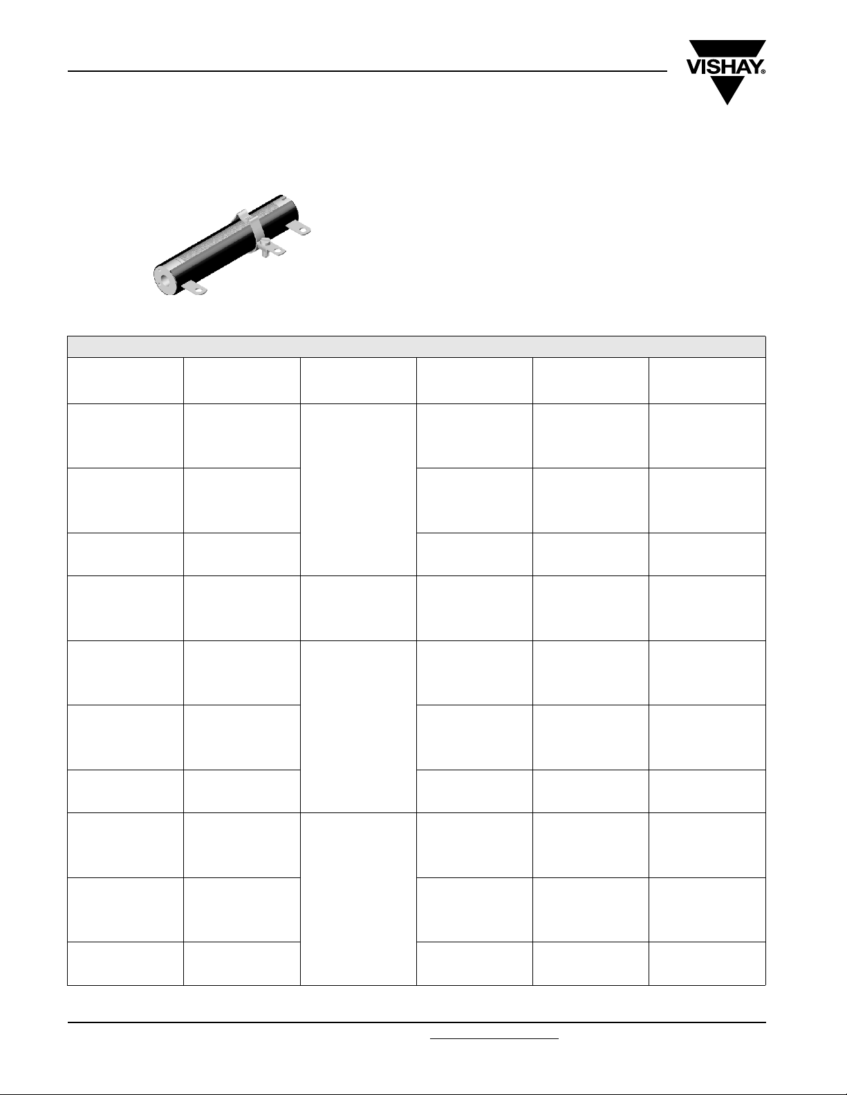
RW
Vishay Draloric
Vitreous Wirewound Resistors
FEATURES
• All welded construction
• Ceramic core
• Models acc. MIL-R-26 available
• Complete vitreous coating for perfect humidity protection
• Adjustable and non inductive design available
• TCR 100...180 ppm/K - WM110 (Class3)
STANDARD ELECTRICAL SPECIFICATIONS
MODEL
RW 10/44 18
RW 10/44 E 11
RW 10/44 Ni 11
RW 12/25 11 120
RW 12/38 15
RW 12/38 E 14
RW 12/38 Ni 14
RW 12/51 25
RW 12/51 E 17
RW 12/51 Ni 17
Note
1. Values in the first line of 10 % tolerance are produced with corrugated ribbon.
www.vishay.com For technical questions contact ww1resistors@vishay.com
88 Revision: 04-Jul-06
POWER RATING
P
40 °C
W
LIMITING VOLTAGE
V
400
350
600
RESISTANCE
1R0 - 3R9 10 E 12
4R3 - 36K 10 E 12
7R5 - 36K 5 E 24
1R0 - 6R2 10 E 12
6R8 - 1K6 10 E 12
6R8 - 1K6 5 E 24
6R2 - 2K4 10 E 12
6R2 - 2K4 5 E 24
R39 - 3R3 10 E 12
3R6 - 13K 10 E 12
33R - 13K 5 E 24
1R0 - 3R6 10 E 12
3R9 - 33K 10 E 12
5R6 - 33K 5 E 24
4R3 - 1K5 10 E 12
5R6 - 1K5 5 E 24
5R6 - 2K2 10 E 12
5R6 - 2K2 5 E 24
1R0 - 3R9 10 E 12
4R3 - 56K 10 E 12
5R6 - 56K 5 E 24
1R0 - 6R2 10 E 12
6R8 - 2K4 10 E 12
6R8 - 2K4 5 E 24
9R1 - 3K6 10 E 12
9R1 - 3K6 5 E 24
1)
RANGE
Ω
---
TOLERANCE
± %
E-SERIES
Document Number: 21005
Page 3
RW
Vitreous Wirewound Resistors
STANDARD ELECTRICAL SPECIFICATIONS
MODEL
RW 12/76 45
RW 12/76 E 27
RW 12/76 Ni 27
RW 20/76 70
RW 20/76 E 42
RW 20/76 Ni 42 1000
RW 20/102 90
RW 20/102 E 55
RW 20/102 Ni 55
RW 30/102 130
RW 30/102 E 80
RW 30/152 220
RW 30/152 E 130
POWER RATING
P
40 °C
W
LIMIT I N G VO LTAG E
V
1000
1000
1400
1600
2500
Vishay Draloric
RESISTANCE
2R0 - 7R5 10 E 12
8R2 - 91K 10 E 12
8R2 - 91K 5 E 24
2R0 - 12R 10 E 12
13R - 4K3 10 E 12
13R - 4K3 5 E 24
16R - 6K2 10 E 12
16R - 6K2 5 E 24
1R0 - 11R 10 E 12
12R - 75K 10 E 12
12R - 75K 5 E 24
1R0 - 18R 10 E 12
20R - 6K8 10 E 12
20R - 6K8 5 E 24
24R - 10K 10 E 12
24R - 10K 5 E 24
18R - 110K 10 E 12
18R - 110K 5 E 24
30R - 10K 10 E 12
30R - 10K 5 E 24
36R - 15K 10 E 12
36R - 15K 5 E 24
2R7 - 22R 10 E 12
24R - 160K 10 E 12
24R - 160K 5 E 24
2R7 - 22R 10 E 12
43R - 15K 10 E 12
43R - 15K 5 E 24
4R7 - 30R 10 E 12
33R - 200K 10 E 12
33R - 200K 5 E 24
4R7 - 30R 10 E 12
75R - 24K 10 E 12
75R - 24K 5 E 24
1)
RANGE
Ω
3R - 16R 10 E 12
3R - 27R 10 E 12
TOLERANCE
± %
E-SERIES
Note
1. Values in the first line of 10 % tolerance are produced with corrugated ribbon.
Document Number: 21005 For technical questions contact ww1resistors@vishay.com
Revision: 04-Jul-06 89
www.vishay.com
Page 4

RW
Vishay Draloric
Vitreous Wirewound Resistors
STANDARD ELECTRICAL SPECIFICATIONS
MODEL
P
40 °C
W
RW 30/203 300
RW 30/203 E 180
RW 30/267 400
RW 30/267 E 240
RW 30/305 480
RW 30/305 E 290
POWER RATING
RW 29
RW 30
RW 31
RW 32
RW 33
RW 35
RW 36
RW 37
RW 38
RW 47
2)
2)
2)
2)
2)
2)
2)
2)
2)
2)
11 400 7R5 - 3K3 5 E 24
11 120 33R - 1K1 5 E 24
14 350 5R6 - 3K 5 E 24
17 600 5R6 - 4K7 5 E 24
26 1000 8R2 - 8K2 5 E 24
55 1400 18R - 20K 5 E 24
78 1600 24R - 30K 5 E 24
113 2500 33R - 47K 5 E 24
159 3600 47R - 68K 5 E 24
210 5000 75R - 91K 5 E 24
LIMITING VOLTAGE
V
3600
5000
6000
RESISTANCE
RANGE
1)
Ω
TOLERANCE
± %
E-SERIES
6R8 - 43R 10 E 12
47R - 270K 10 E 12
47R - 270K 5 E 24
6R8 - 43R 10 E 12
100R - 36K 10 E 12
100R - 36K 5 E 24
8R2 - 68R 10 E 12
75R - 390K 10 E 12
75R - 390K 5 E 24
8R2 - 68R 10 E 12
150R - 47K 10 E 12
150R - 47K 5 E 24
10R - 68R 10 E 12
75R - 300K 10 E 12
75R - 300K 5 E 24
10R - 68R 10 E 12
160R - 56K 10 E 12
160R - 56K 5 E 24
Note
1. Values in the first line of 10 % tolerance are produced with corrugated ribbon.
2. Model according to MIL-R-26.
www.vishay.com For technical questions contact ww1resistors@vishay.com
Document Number: 21005
90 Revision: 04-Jul-06
Page 5

RW
Vitreous Wirewound Resistors
GLOBAL PART NUMBER INFORMATION
New Global Part Numbering: RW0104411009JLX000 (preferred part number format)
1044 1001W0 JLX 09R 00
MODEL SIZE
RW 01044 = 10/44
01225 = 12/25
01238 = 12/38
01251 = 12/51
01276 = 12/76
02076 = 20/76
20102 = 20/102
30102 = 30/102
30152 = 30/152
30203 = 30/203
30267 = 30/267
30305 = 30/305
00029 = 29
00030 = 30
00031 = 31
00032 = 32
00033 = 33
00035 = 35
00036 = 36
00037 = 37
00038 = 38
00047 = 47
SPECIAL
CHARACTER
0 = neutral
1 = E
2 = NI
7 = FST
C = E FST
H = NI FST
Z = value
overflow (BV)
(Note: NI is
also known
as SWI)
VALUE TOLERANCE PACKING SPECIAL
3 digit value
1 digit multiplier
Multiplier:
-3
7 = *10
-2
8 = *10
-1
9 = *10
0
0 = *10
1
1 = *10
2
2 = *10
3
3 = *10
4
4 = *10
J = ± 5.0 %
K = ± 10.0 %
(see
Packing table)
Vishay Draloric
The 5 digit BV number will be
encoded using a 36 character
code. This code contains
numbers 0...9 and letters A...Z
(36 characters total) and allows
to encode at least 46 655 five
digit BV numbers.
000 = standard
Historical Part Number example: RW 10 x 44 E 10R 5 % (will continue to be accepted)
RW 10 x 44 E 10R 5 %
HISTORICAL MODEL SPECIAL CHARACTER VALUE TOLERANCE
PACKING TABLE
SAP DESCRIPTION TYPE
LX Loose pack, without quantity all
ZX Special pack (with BV #), without quantity all
Note: LX = B29 on Dale legacy
Document Number: 21005 For technical questions contact ww1resistors@vishay.com
Revision: 04-Jul-06 91
ZX = S51 on Dale legacy
www.vishay.com
Page 6

RW
Vishay Draloric
Vitreous Wirewound Resistors
DIMENSIONS
L
d
2.5
[0.098]
MODEL
MM D
e
max.
b
a
RW 10/44
2.5
[0.098]
RW 12/25
RW 10/44 E
RW 10/44 Ni
1)
[0.5 (0.618)]
2)
RW 29
12.7 (15.7)
RW 30
15.1 (18.1)
[0.595 (0.713)]
L ± 1.6 mm 44.4 [1.748] 25.4 [1.000] 38.1 [1.500] 50.8 [2.000] 76.2 [3.000] 76.2 [3.000]
a 33.4 [1.315] 14.4 [0.570] 27.1 [1.070] 39.8 [1.570] 65.2 [2.570] 63.2 [2.490]
a
1
31.4 [1.236] - 25.1 [0.990] 37.8 [1.490] 63.2 [2.490] 63.2 [2.490]
b 6 [0.236] 6 [0.240] 6 [0.240] 6 [0.240] 6 [0.240] 8 [0.310]
b
1
5 [0.197] - 5 [0.200] 5 [0.200] 5 [0.200] 5 [0.200]
c 16.5 [0.650] 17.5 [0.690] 17.5 [0.690] 17.5 [0.690] 17.5 [0.690] 22 [0.870]
c
1
18.5 [0.728] - 19 [0.750] 19 [0.750] 19 [0.750] 23 [0.910]
d 4.5 [0.177] 5.5 [0.220] 5.5 [0.220] 5.5 [0.220] 5.5 [0.220] 12 [0.470]
e 3.2 [0.126] 3.2 [0.130] 3.2 [0.130] 3.2 [0.130] 3.2 [0.130] 4.2 [0.170]
e
1
2.8 [0.110] - 3.2 [0.130] 3.2 [0.130] 3.2 [0.130] 3.2 [0.130]
s 0.6 [0.024] 0.6 [0.020] 0.6 [0.020] 0.6 [0.020] 0.6 [0.020] 0.8 [0.030]
Weight (Grams) 101010151530
MODEL
MM D
max.
RW 20/102
RW 20/102 E
RW 20/102 Ni
1)
RW 35
23 (26)
2)
[0.906 (1.024)]
RW 30/102
RW 30/102 E
RW 36
33.3 (36.3)
[1.310 (1.430)]
L ± 1.6 mm 101.6 [4.000] 101.6 [4.000] 152.4 [6.000] 203.2 [8.000] 266.7 [10.50] 304.8 [12.00]
a 88.6 [3.490] 88.6 [3.490] 139.4 [5.490] 190.2 [7.490] 253.7 [9.990] 291.8 [11.49]
a
1
88.6 [3.490] 88.6 [3.490] 139.4 [5.490] 190.2 [7.490] 253.7 [9.990] 291.8 [11.49]
b 8 [0.310] 8 [0.310] 8 [0.310] 8 [0.310] 8 [0.310] 8 [0.310]
b
1
5 [0.200] 8 [0.310] 8 [0.310] 8 [0.310] 8 [0.310] 8 [0.310]
c 22 [0.870] 31 [1.220] 31 [1.220] 31 [1.220] 31 [1.220] 31 [1.220]
c
1
23 [0.910] 27 [1.060] 27 [1.060] 27 [1.060] 27 [1.060] 27 [1.060]
d 12 [0.470] 18.5 [0.730] 18.5 [0.730] 18.5 [0.730] 18.5 [0.730] 18.5 [0.730]
e 4.2 [0.170] 4.2 [0.170] 4.2 [0.170] 4.2 [0.170] 4.2 [0.170] 4.2 [0.170]
e
1
3.2 [0.130] 4.2 [0.170] 4.2 [0.170] 4.2 [0.170] 4.2 [0.170] 4.2 [0.170]
s 0.8 [0.030] 0.8 [0.030] 0.8 [0.030] 0.8 [0.030] 0.8 [0.030] 0.8 [0.030]
Weight (Grams) 62 136 200 260 330 430
Note
1. Numbers in (parenthesis) represent the Dimension D
2. Model according to MIL-R-26.
www.vishay.com For technical questions contact ww1resistors@vishay.com
92 Revision: 04-Jul-06
D
max.
c
b
s
Adjustable lug with
contact stud
1
DIMENSIONS in millimeters [inches]
RW 12/38
RW 12/38 E
2)
RW 12/38 Ni
RW 31
2)
15.1 (18.1)
[0.595 (0.713)]
RW 30/152
RW 30/152 E
2)
RW 37
2)
33.3 (36.3)
[1.310 (1.430)]
for resistor produced with corrugated ribbon.
max
RW 12/51
RW 12/51 E
RW 12/51 Ni
RW 32
15.1 (18.1)
[0.595 (0.713)]
RW 30/203
RW 30/203
RW 38
33.3 (36.3)
[1.310 (1.430)]
e
1
c
1
0.8 [0.030]
thickness
1.65 + 0.1
[0.065 + 0.004]
6.3 + 0.1
[0.248 + 0.004]
FST A 6.3 mm/DIN 46244
(at end terminals only)
2)
[0.595 (0.713)]
RW 30/267 E
2)
[1.310 (1.430)]
RW 12/76
RW 12/76 E
RW 12/76 Ni
RW 33
2)
15.1 (18.1)
RW 30/267
2)
RW 47
33.3 (36.3)
Document Number: 21005
[0.157 + 0.020]
4 + 0.5
8
± 0.1
[0.310 + 0.004]
a
1
RW 20/76
RW 20/76 E
RW 20/76 Ni
23 (26)
[0.906 (1.024)]
RW 30/305
RW 30/305 E
33.3 (36.3)
[1.310 (1.430)]
Page 7

RW
Vitreous Wirewound Resistors
120
% NI REWE
100
OP DETAR
80
60
40
20
0
- 55 50 150 250 350
AMBIENT TEMPERATURE IN
RW 10/44
40
C
500
°
NI ESIR E
400
R
U
300
TA
R
EPMET
200
Derating
C
500
°
NI ESIR ERUTAREPMET
400
300
200
RW 12/25
°
C
Vishay Draloric
RW 12/51
RW 12/38
100
0
0 5 10 15 20 25
Temperature Rise
C
500
°
NI
E
400
SIR E
R
UTA
300
R
E
P
200
M
ET
100
0
0 20 40 60 80 100
MIL-R-26
Char.V
MIL-R-26
Char.V
RW 12/76
RW 20/76
Temperature Rise
C
500
°
N
I
E
400
S
I
R
E
R
U
300
TA
R
EP
200
M
E
T
100
RW 30/152
POWER IN W
POWER IN W
RW 30/267
100
0
0 5 10 15 20 25
Temperature Rise
C
500
°
NI ESIR ER
400
U
300
TA
REPMET
200
100
0
0 50 100 150 200 250
RW 20/102
MIL-R-26
Char.V
MIL-R-26
Char.V
RW 30/102
Temperature Rise
C
500
°
NI ESIR E
400
R
U
300
TARE
P
200
M
E
T
100
RW 12/25
RW 10/44
POWER IN W
POWER IN W
0
0 100 200 300 400 500
Temperature Rise
MIL-R-26
Char.V
POWER IN W
Document Number: 21005 For technical questions contact ww1resistors@vishay.com
0
0 100 200 300 400 500
Temperature Rise
MIL-R-26
Char.V
POWER IN W
www.vishay.com
Revision: 04-Jul-06 93
 Loading...