

Page 1
6121 Baker Road,
Suite 108
Minnetonka, MN 55345
www.chtechnology.com
Phone (952) 933-6190
Fax (952) 933-6223
1-800-274-4284
Thank you for downloading this document from C&H Technology, Inc.
Please contact the C&H Technology team for the following questions -
Technical ● Application ● Assembly ● Availability ● Pricing
Phone – 1-800-274-4284
E-Mail – sales@chtechnology.com
www.chtechnology.com - SPECIALISTS IN POWER ELECTRONIC COMPONENTS AND ASSEMBLIES
-
www.chtechnology.com
Page 2
RTOP
Vishay Sfernice
Power Resistor for Mounting onto a Heatsink
Thick Film Technology
FEATURES
• 1 % tolerance available
• High power rating = 200 W
• Wide ohmic value range = 0.046 to 1 MΩ
• Non inductive
• Easy mounting
• Low thermal radiation of the case
• Standard Isotop case (SOT 227 B)
This series of thick film power resistors include modules which can incorporate up to 2 different resistor values in the same
SOT 227B package. Two types of terminations are available along with a 4 terminal device for measurement applications in the
case of the single resistor version. This product range benefits from Vishay Sfernice’s experience in thick film power resistor
technology i.e. high power: volume ratio, low tolerance or individual resistors and excellent overload capabilities (due to the
trimming technique).
RoHS
COMPLIANT
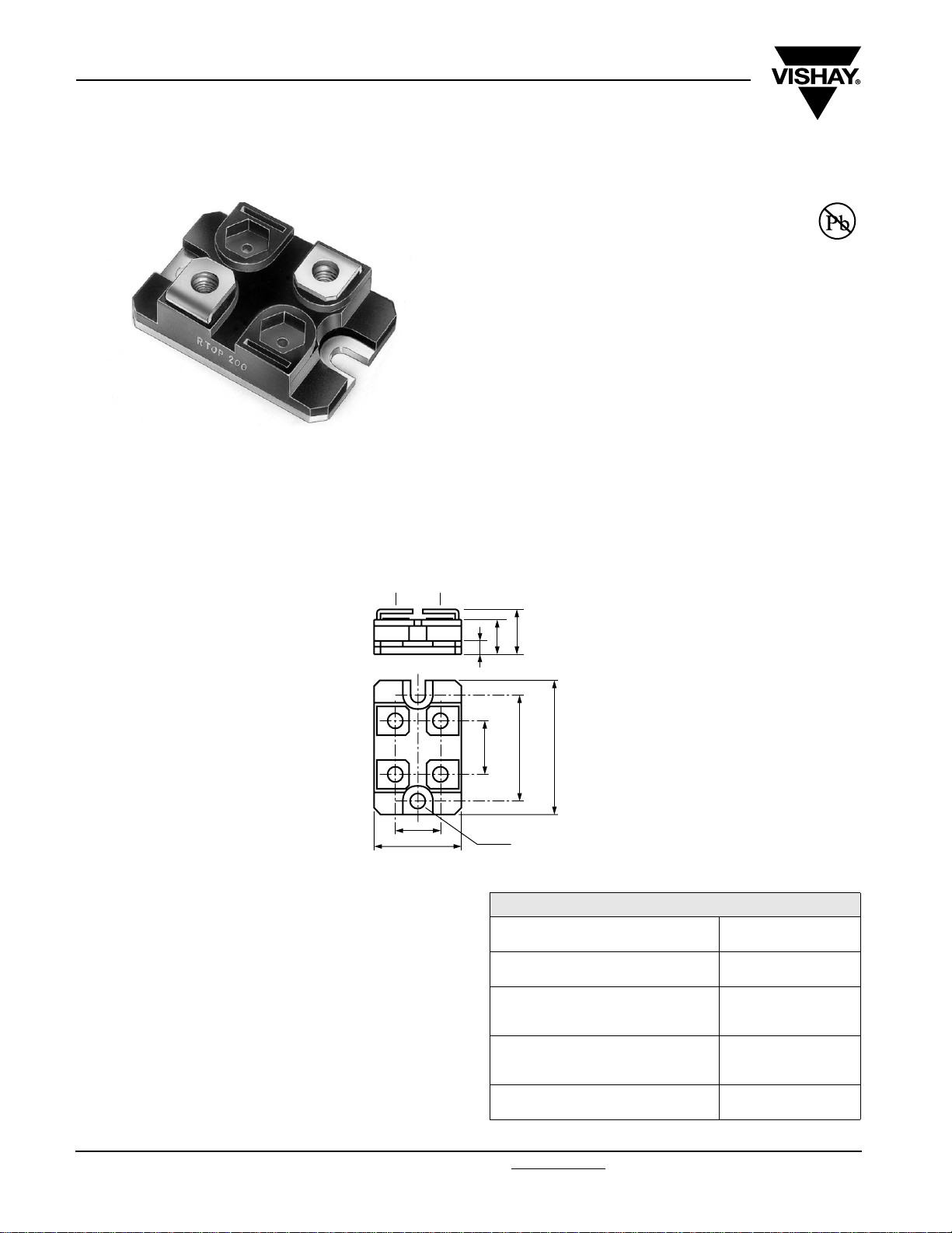
DIMENSIONS in millimeters
RTOP
• Tolerances unless otherwise specified: ± 0.3 mm
MECHANICAL SPECIFICATIONS
Mechanical Protection
Substrate
Alumina on insulated base
Resistive Element
End Connections
Tightening Torque Connections
Tightening Torque Heatsink
Weight
Insulated case
Cermet
V connections: screw M4 x 6
1 Nm
2 Nm
30 g max.
V Connections
12.6
25
12.6
10
4
16
Ø 4.2
39
30
ELECTRICAL SPECIFICATIONS
Resistance Range 0.046 to 1 MΩ
Standard Tolerance ± 1 % to ± 10 %
Power Rating
50 W to 200 W
at + 25 °C
Temperature Coefficient
ENVIRONMENTAL SPECIFICATIONS
Temperature Range
Climatic Category
www.vishay.com For technical questions, contact: sfer@vishay.com
1 Revision: 14-Nov-08
- 55 °C to + 125 °C
55/125/56
(- 55 °C to + 125 °C)
Insulation Resistance > 10
Standard
± 300 ppm/°C (R < 1)
± 150 ppm/°C (R > 1)
6
MΩ
Document Number: 50045
Page 3

RTOP
Power Resistor for Mounting onto a Heatsink
Vishay Sfernice
Thick Film Technology
PERFORMANCE
TESTS CONDITIONS REQUIREMENTS
Momentary Overload
Rapid Temperature Change
Load Life
Humidity (Steady State)
NF EN 140000 CEI 115_1
2.5 Pn/5 s U
NF EN 140000 CEI 68214 Test Na
5 cycles - 55 °C + 125 °C
NF EN 140000 CEI 115_1
Pn at 25 °C 1000 h
MIL STD 202 Method 103 B Test D
56 days 95 % R.H.
< 2 U
S
L
SPECIAL FEATURES
MODEL RTOP 200 RTOP 100 DRTOP 100 DRTOP 50
Power Rating at + 25 °C
Chassis Mounted Resistors
Unmounted Resistors
200 W
5 W
100 W
5 W
< ± (0.25 % + 0.05 Ω)
< ± (0.25 % + 0.05 Ω)
< ± (0.5 % + 0.05 Ω)
< ± (0.5 % + 0.05 Ω)
100 W
3.5 W
50 W
3.5 W
Thermal Resistance (Per Resistor) 0.5 °C/W 1 °C/W 0.5 °C/W 1 °C/W
Limiting Voltage U
Dielectric Strength
Connections/Chassis
Dielectric Strength
Connections/Resistors
Ohmic Value Range 0.046 to 1 MΩ 0.092 to 1 MΩ
Tolerance ± 1 % to ± 10 % ± 1 % to ± 10 %
Electrical Diagrams
1500 V 1500 V 500 V 500 V
L
(1)
(1)
2500 V, 1 min
10 mA max.
- -
2500 V, 1 min
10 mA max.
R
2500 V, 1 min
10 mA max.
2500 V, 1 min
10 mA max.
2500 V, 1 min
10 mA max.
2500 V, 1 min
10 mA max.
R2
R1
R
Shunt Version
Note
(1)
MIL STD 202 Method 301
Document Number: 50045 For technical questions, contact: sfer@vishay.com
Revision: 14-Nov-08 2
www.vishay.com
Page 4

RTOP
Vishay Sfernice
Power Resistor for Mounting onto a Heatsink
Thick Film Technology
CHOICE OF THE HEATSINK
The user must choose the heatsink according to the working
conditions of the component (power, room temperature).
Maximum working temperature must not exceed 125 °C.
The dissipated power is simply calculated by the following
ratio:
-------------------------------------------------------------
P
R
P: Expressed in W
ΔT: Difference between maximum working
temperature and room temperature.
R
: Thermal resistance value measured between
TH (j - c)
resistive layer and outer side of the resistor. It is
the thermal resistance of the component (see
Table Special Features).
R
: Thermal resistance value measured between
TH (c - a)
outer side of the resistor and room temperature.
It is the thermal resistance of the heatsink
depending on the heatsink itself (type, shape)
and the quality of the fastening device.
Example:
R
TH (c - a)
: For RTOP 200 power rating 130 W at ambient
temperature + 30 °C.
Thermal resistance (see table 1) R
ΔT 125 °C - 30 °C - 95 °C≤≤
R
TH (j - c)RTH (c - a)
R
TH (j - c)
R
TH (c - a)
0.5 °C/W≤
0.73 °C/W - 0.5 °C/W 0.23 °C/W≤≤
ΔT
+[]
TH j c–()RTH c a–()
ΔT
95
-------
----------
P
130
TH (j - c)
0.73 °C/W== =+
1()=
: 0.5 °C/W
OVERLOADS
The applied power is 2.5 x rated power for 5 s with a max.
voltage of 2 x nominal voltage.
Accidental overload: The values indicated in the graph
below are applicable to resistors in air or mounted onto a
heatsink.
In case of multi-resistor devices, (DRTOP, TROP and
QROP) the results apply to each resistor value in the device.
RECOMMENDATIONS FOR MOUNTING
ONTO A HEATSINK
Surfaces in contact must be carefully cleaned.
The heatsink must have an acceptable flatness:
from 0.05 mm to 0.1 mm/100 mm.
Roughness of the heater must be around 6.3 µm.
In order to improve thermal conductivity, surfaces in contact
(alumina, heatsink) are laid on with a silicone grease (type SI
340 from Rhône-Poulenc or Dow 340 from Dow Corning).
Tightening torque on heater: 2 Nm
For the electrical connections, it is recommended to use
M4 x 6 screws and if necessary a washer of 1mm thickness.
The recommended screw tightening torque is 1 Nm.
ENERGY CURVE
1000
100
10
1
ENERGY IN JOULES
0.1
0.01
1.10-7 1.10-6 1.10-5 1.10-4 1.10-3 1.10-2 1.10-1 1
OVERLOAD DURATION IN SECONDS
RTOP DRTOP
www.vishay.com For technical questions, contact: sfer@vishay.com Document Number: 50045
3 Revision: 14-Nov-08
Page 5

RTOP
Power Resistor for Mounting onto a Heatsink
Vishay Sfernice
Thick Film Technology
POWER RATING CHART
The temperature of the heater should be maintained in the limit specified. To improve the thermal conductivity, surfaces in
contact should be laid on with a silicon grease and the torque applied on the screw for tightening should be around 2 Nm.
MARKING
Series, style, ohmic value (in), tolerance (in %), manufacturing date, VISHAY trade mark.
PACKAGING
Box of 10 units
100
80
60
40
% RATED POWER
20
0
0 20 40 60 80 100 120 140
HEATSINK TEMPERATURE IN DEGREES CELSIUS
ORDERING INFORMATION
RTOP 200 5U ± 1 % ± % V
DRTOP 50 150U 5 % 15U 5 % V XXX BO10 e
R1 T1 R2
MODEL STYLE OHMIC
RTOP
DRTOP
100
50
VAL UE
ABSOLUTE TOLERANCE PER
Optional
± 1 %
± 2 %
± 5 %
± 10 %
RESISTOR
To be precise
for each
resistor
CONNECTIONS CUSTOM
V: Screw
VS: RTOP Shunt
DESIGN
Optional
PACKAGING LEAD
(Pb)-FREE
GLOBAL PART NUMBER INFORMATION
OP1 0 0V 5 0 R KR TD R50B
GLOBAL
MODEL
RTOP
DRTOP
Document Number: 50045 For technical questions, contact: sfer@vishay.com
Revision: 14-Nov-08 4
SIZE LEADS OHMIC VALUE OHMIC VALUE TOL. PACKAGING SPECIAL
100
200
F = Faston type
V = Screw
VS, FS =
RTOP Shunt
If RTOP: The first three
digits are significant figures
and the last digit specifies
the number of zeros to
follow.
R designates decimal point.
48R7 = 48.7 Ω
4871 = 4870 Ω
1002 = 10 000 Ω
R010 = 0.01 Ω
R680 = 0.68 Ω
2700 = 2700 Ω = 2K7 Ω
Blank if RTOP.
If DRTOP: The first two
digits are significant figures
and the last digit specifies
the number of zeros to
follow.
R designates decimal point.
48R = 48 Ω
487 = 487 Ω
F = 1 %
G = 2 %
J = 5 %
K = 10 %
B = Box
10 pieces
As applicable
Ex = UA1
www.vishay.com
Page 6

Legal Disclaimer Notice
Vishay
Disclaimer
All product specifications and data are subject to change without notice.
Vishay Intertechnology, Inc., its affiliates, agents, and employees, and all persons acting on its or their behalf
(collectively, “Vishay”), disclaim any and all liability for any errors, inaccuracies or incompleteness contained herein
or in any other disclosure relating to any product.
Vishay disclaims any and all liability arising out of the use or application of any product described herein or of any
information provided herein to the maximum extent permitted by law. The product specifications do not expand or
otherwise modify Vishay’s terms and conditions of purchase, including but not limited to the warranty expressed
therein, which apply to these products.
No license, express or implied, by estoppel or otherwise, to any intellectual property rights is granted by this
document or by any conduct of Vishay.
The products shown herein are not designed for use in medical, life-saving, or life-sustaining applications unless
otherwise expressly indicated. Customers using or selling Vishay products not expressly indicated for use in such
applications do so entirely at their own risk and agree to fully indemnify Vishay for any damages arising or resulting
from such use or sale. Please contact authorized Vishay personnel to obtain written terms and conditions regarding
products designed for such applications.
Product names and markings noted herein may be trademarks of their respective owners.
Document Number: 91000 www.vishay.com
Revision: 18-Jul-08 1
 Loading...