

Page 1
6121 Baker Road,
Suite 108
Minnetonka, MN 55345
www.chtechnology.com
Phone (952) 933-6190
Fax (952) 933-6223
1-800-274-4284
Thank you for downloading this document from C&H Technology, Inc.
Please contact the C&H Technology team for the following questions -
Technical ● Application ● Assembly ● Availability ● Pricing
Phone – 1-800-274-4284
E-Mail – sales@chtechnology.com
www.chtechnology.com - SPECIALISTS IN POWER ELECTRONIC COMPONENTS AND ASSEMBLIES
-
www.chtechnology.com
Page 2
RTO 20
Vishay Sfernice
Power Resistors, Thick Film Technology
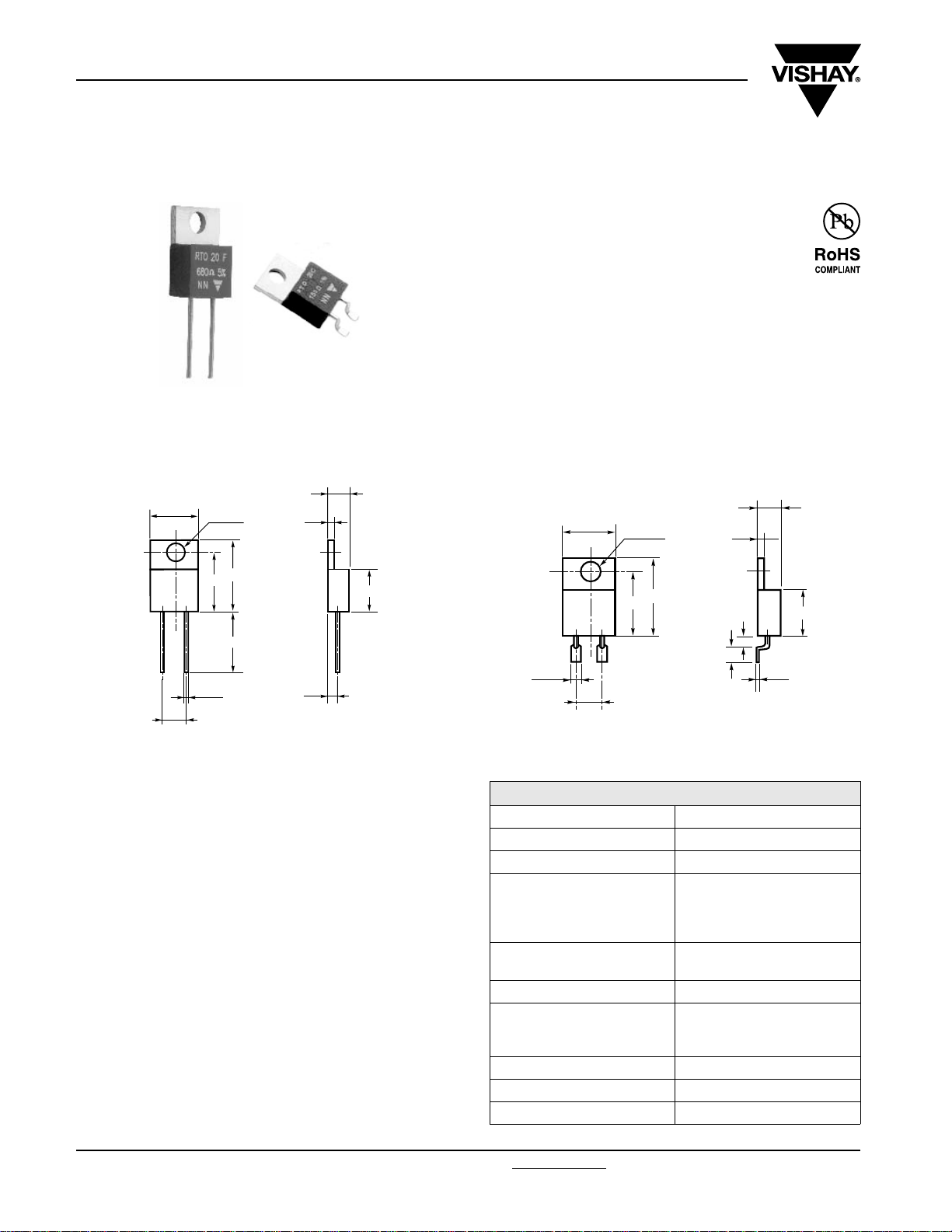
The well known TO 220 package is compact and easy to
mount.
DIMENSIONS in millimeters
RTO 20F - LEADED
4.5
10.1
Ø 3.6
1.3
FEATURES
• 20 W at 25 °C heatsink mounted
• High power dissipation to size ratio
• Wide resistance range from 0.01 Ω to 550 kΩ
• Negligible inductance
• Easy mounting
• TO 220 package: Compact and easy to mount
Two versions of this thick film resistor are available:
• A radial leaded version for PCB mounting
• A flat lead version for surface mounting
RTO 20C - FOR SURFACE MOUNTING
4.5
10.1
Ø 3.6
1.3
15
12.5
13.7
Ø 0.8
5.08
• Tolerance unless otherwise specified: ± 0.4 mm
2.5
8.8
MECHANICAL SPECIFICATIONS
Mechanical Protection Insulated case
Resistive Element Thick Film
Connections Tinned copper
Weight 2.2 g max.
DIMENSIONS
Standard Package TO 220
Insulated case
ENVIRONMENTAL SPECIFICATIONS
Temperature Range - 55 °C to + 155 °C
Climatic Category 55/155/56
Sealing Sealed container
Solder immersion
Flammability IEC 60695-11-5
2 applications 30 s seperated
by 60 s
15
12.5
2
3
1.6
5.08
• Only for RTO 20 version C = during surface mount soldering temperature profile
must not cause the metal tab of this device to exceed 220 °C.
8.8
0.3
ELECTRICAL SPECIFICATIONS
Resistance Range 0.010 Ω to 550 kΩ serie E24
Tolerances (Standard) ± 1 % to ± 10 %
Dissipation and Associated: Onto a heatsink
20 W at + 25 °C
Thermal Resistance
and Nominal Power
Temperature Coefficient
Standard (- 55 °C; + 150 °C)
Limiting Element Voltage U
Dielectric Strength
MIL STD 202
Insulation Resistance ≥ 10
Inductance ≤ 0.1 µH
Critical Resistance 3.12 kΩ
L
R
: 6.5 °C/W
TH (j - c)
free air:
2 W at + 25 °C
See Performance table
± 150 ppm/°C
250 V
2000 V
- 1 min - 10 mA max.
RMS
(between terminals
and heatsink)
6
MΩ
www.vishay.com For technical questions, contact: sfer@vishay.com Document Number: 50005
14 Revision: 24-Nov-08
Page 3

RTO 20
Power Resistors, Thick Film Technology
Vishay Sfernice
PERFORMANCE
TESTS CONDITIONS REQUIREMENTS
EN 60115-1
Momentary Overload
Rapid Temperature Change
Load Life
Humidity (Steady State)
High Temperature Exposure
Vibration MIL STD 202, Method 204 C Test D ± (0.2 % + 0.005 Ω)
Terminal Strength MIL STD 202, Method 211 Test A1 ± (0.2 % + 0.005 Ω)
Shock
2 Pr 5 s for R < 2 Ω
1.6 Pr 5 s for R ≥ 2 Ω
Us < 1.5 UL
EN 60115-1/60068-2-14
5 cycles
- 55 °C to + 155 °C
EN 60115-1
1000 h Pr at + 25 °C
EN 60115-1
56 days R.H. 95 %
NF EN 140 000
1000 h - 40 % Pr at + 100 °C
IEC 60115-1
IEC 60068-2-27
Saw tooth: 100 g/6 ms
± (0.25 % + 0.005 Ω)
± (0.5 % + 0.005 Ω)
± (1 % + 0.005 Ω)
± (0.5 % + 0.005 Ω)
± (0.5 % + 0.005 Ω)
± (0.5 % + 0.005 Ω)
SPECIAL FEATURES
Resistance Values ≥ 0.01 ≥ 0.015 ≥ 0.1 ≥ 0.5
Tolerances ± 1 % at ± 10 %
Typical Temperature
Coefficient Range
(- 55 °C to + 155 °C)
Note
• For very low ohmic values, TCR for information
± 900 ppm/°C ± 700 ppm/°C ± 250 ppm/°C ± 150 ppm/°C
CHOICE OF THE HEATSINK
The user must choose according to the working conditions of the component (power, room temperature).
Maximum working temperature must not exceed 155 °C. The dissipated power is simply calculated by the following ratio:
1()
TH (j - c)
ΔT
+ R
TH (c - a)
-----------------------------------------------------------
P =
[]
R
P: Expressed in W
ΔT: Difference between maximum working temperature and room temperature
R
: Thermal resistance value measured between resistive layer and outer side of the resistor. It is the thermal
TH (j - c)
resistance of the component: (Special Features table)
R
: Thermal resistance value measured between outer side of the resistor and room temperature. It is the thermal
TH (c - a)
resistance of the heatsink itself (type, shape) and the quality of the fastening device.
Example:
R
Thermal resistance R
:For RTO 20 power rating 10 W at ambient temperature + 25 °C
TH (c - a)
: 6.5 °C/W
TH (j - c)
Considering equation (1) we have:
ΔT 155 °C - 25 °C 130 °C==
ΔT
130
-------
R
TH (j - c)
R
TH (c - a)
+ R
= 13 °C/W - 6.5 °C/W = 6.5 °C/W
TH (c - a)
=
----------
=
P
= 13 °C/W
10
Document Number: 50005 For technical questions, contact: sfer@vishay.com
Revision: 24-Nov-08 15
www.vishay.com
Page 4

RTO 20
Vishay Sfernice
Power Resistors, Thick Film Technology
OVERLOADS
In any case the applied voltage must be lower than the
maximum overload voltage of 375 V.
The values indicated on the graph below are applicable to
resistors in air or mounted onto a heatsink.
ENERGY CURVE
100
10
1
ENERGY IN JOULES
0.1
0.01
-7
10
-6
10
-5
10
OVERLOAD DURATION IN S
-4
10
-3
10
-2
10
10
MARKING
Model, style, resistance value (in Ω), tolerance (in %),
manufacturing date, VISHAY trademark.
POWER RATING CHART
The temperature of the heatsink should be maintained within
the limits specified.
To improve the thermal conductivity, surfaces in contact
should be coated with a silicone grease and the torque
applied on the screw for tightening should be around 1 Nm.
Spring clip can also be used to mount the component on an
heatsink (ex: Kunze, clip KU4-498).
120
100
75
50
% RATED POWER
25
-1
0
0
20
60
40
HEATSINK TEMPERATURE IN °C
100
80
120
140 155
PACKAGING
Tube of 50 units
ORDERING INFORMATION
RTO 20 F U68 5 % xxx TU50 e3
MODEL STYLE CONNECTIONS RESISTANCE VALUE TOLERANCE CUSTOM DESIGN PACKAGING LEAD (Pb)-FREE
F: Radial leads
C: Surface mount
± 1 %
± 2 %
± 5 %
± 10 %
Optional
on request:
special TCR,
shape etc.
GLOBAL PART NUMBER INFORMATION
020FR68 0T3T OR 0JE
GLOBAL
MODEL
RTO 020 F = Radial leads
SIZE LEADS OHMIC VALUE TOLERANCE PACKAGING
C = Surface mount
The firts four digits are
significant figures and the last
digit specifies the number of
zeros to follow.
F = 1 %
G = 2 %
J = 5 %
K = 10 %
T = Tube
Size 30 and 50:
Tube 50 pieces
R designates decimal point.
48R70 = 48.7 Ω
48701 = 48 700 Ω
10002 = 100 000 Ω
R0100 = 0.01 Ω
R6800 = 0.68 Ω
27000 = 2700 Ω = 2K7 Ω
www.vishay.com For technical questions, contact: sfer@vishay.com Document Number: 50005
16 Revision: 24-Nov-08
Page 5

Legal Disclaimer Notice
Vishay
Disclaimer
All product specifications and data are subject to change without notice.
Vishay Intertechnology, Inc., its affiliates, agents, and employees, and all persons acting on its or their behalf
(collectively, “Vishay”), disclaim any and all liability for any errors, inaccuracies or incompleteness contained herein
or in any other disclosure relating to any product.
Vishay disclaims any and all liability arising out of the use or application of any product described herein or of any
information provided herein to the maximum extent permitted by law. The product specifications do not expand or
otherwise modify Vishay’s terms and conditions of purchase, including but not limited to the warranty expressed
therein, which apply to these products.
No license, express or implied, by estoppel or otherwise, to any intellectual property rights is granted by this
document or by any conduct of Vishay.
The products shown herein are not designed for use in medical, life-saving, or life-sustaining applications unless
otherwise expressly indicated. Customers using or selling Vishay products not expressly indicated for use in such
applications do so entirely at their own risk and agree to fully indemnify Vishay for any damages arising or resulting
from such use or sale. Please contact authorized Vishay personnel to obtain written terms and conditions regarding
products designed for such applications.
Product names and markings noted herein may be trademarks of their respective owners.
Document Number: 91000 www.vishay.com
Revision: 18-Jul-08 1
 Loading...