

Page 1

6121 Baker Road,
Suite 108
Minnetonka, MN 55345
www.chtechnology.com
Phone (952) 933-6190
Fax (952) 933-6223
1-800-274-4284
Thank you for downloading this document from C&H Technology, Inc.
Please contact the C&H Technology team for the following questions -
Technical
Application
Assembly
Availability
Pricing
Phone – 1-800-274-4284
E-Mail – sales@chtechnology.com
www.chtechnology.com - SPECIALISTS IN POWER ELECTRONIC COMPONENTS AND ASSEMBLIES - www.chtechnology.com
Page 2
RSSD
Vishay Sfernice
Adjustable Wirewound Vitreous Resistors
Low Ohmic Values (0.10 Ω available)
FEATURES
• High power rating: 16 W to 600 W at 25 °C
• Heavy overloads 10 Pn 15 s ≤ 1 %
• Low ohmic values 0.10 Ω available
• High long term stability drift < 1.5 % after 1000 h
• Excellent withstanding of thermal shock
• Mechanical strength
CS collars
RSSD medium and high power resistors are noted for their ability to withstand heavy transient and severe shock and vibration
conditions. They complement the ohmic range of Vishay styles RW, RWST and RA in the low value area, and can be tapped by
means of adjustable collars. Standard RSSD resistors have a single adjustable collar.
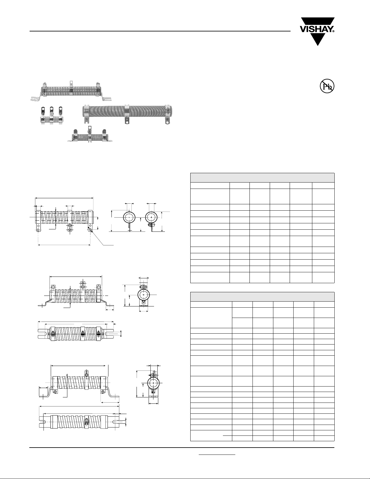
DIMENSIONS
WELDED STAINLESS STEEL 304 L COLLARS “AN” TYPE 1
Ty pe 1
Solded
¯ C
P
¯ Q
ZF
¯ B
A
F
R
D
SCREWED STAINLESS STEEL 304 L COLLARS “CS” TYPE 1
A
J
¯ B
26
G
H
15
L
SCREWED STAINLESS STEEL 304 L COLLARS “CS” TYPE 2
A
23
¯ B
G
H
58
15
L
Ty pe 2
Screwed
¯ C
E
¯ C
K
M
J
K
P
¯ C
M
• Fire proof
DIMENSIONS in millimeters
RSSD STYLE 8 × 34 10 × 50 13 × 70 16 × 94 20 × 117
Connection
A ± 2 34 50 70 94 117
Ø B max. 10 11.5 14.5 18 22
Ø C min. 4.1 5 6.7 9.2 12.6
D 27 ± 2 40 ± 2 56 ± 2 78 ± 2 98 ± 2
E 20 ± 05 22 ± 0.5 24 ± 0.5 26.5 ± 0.5 31 ± 0.7
F+ 0.5
+ 0
P 28 ± 1 31 ± 1 34 ± 1 38 ± 1 42 ± 1
Ø Q 3.2 4.2 4.2 4.2 4.2
R 16 ± 0.5 18 ± 0.5 20 ± 0.5 21 ± 0.5 24 ± 0.7
Z approx. 1 1.5 3.5 4 5
Average unit AN
weight in g
* CS connections on request
AN
type 1ANtype 1
5 6.35 6.35 6.35 6.35
10 22 38 55 80
AN
type 1
CS*
AN
type 1ANtype 1
DIMENSIONS in millimeters
RSSD STYLE 25 × 138 25 × 168 30 × 250 40 × 370 50 × 373
Connection
A ± 2 138 168 250 370 373
Ø B max. 27 27 32 43 53
Ø C min. 16.4 16.4 21.3 22.3 27.1
D 117 ± 2 147 ± 2 227 ± 2.5 332 ± 3 332 ± 3
E 33.5 ± 1 33.5 ± 1 36 ± 1 57 ± 1.5 63 ± 1.5
F + 0.5
+ 0
G- 4
- 0
H- 4
- 0
J 50 ± 1.5 50 ± 1.5 60 ± 1.5 69 max. 80 max.
K 27 ± 1 27 ± 1 30 ± 1 45 ± 1 51 ± 1.5
L ± 0.5 6.5 6.5 9 9 9
M ± 0.5 2424253030
P 51 ± 1.5 51 ± 1.5 55 ± 1.5 81.5 max. 92.5 max.
Ø Q 5.7 5.7 5.7 9.2 9.2
R 28.5 ± 1 28.5 ± 1 31 ± 1 45 ± 1.5 51 ± 1.5
Z approx. 6 6 5 10 11.5
Average unit
weight in g
AN
type 1ANtype 1ANtype 1ANtype 2ANtype 2
CS
type 1CStype 1CStype 1CStype 2CStype 2
9 9 13 18 18
199 229 317 432 432
169 199 287 405 405
AN 90 115 240 845 1270
CS 135 160 290 925 1350
www.vishay.com For technical questions, contact: sfer@vishay.com Document Number: 50020
70 Revision: 24-Jan-07
Page 3
RSSD
Adjustable Wirewound Vitreous Resistors
Vishay Sfernice
Low Ohmic Values (0.10 Ω available)
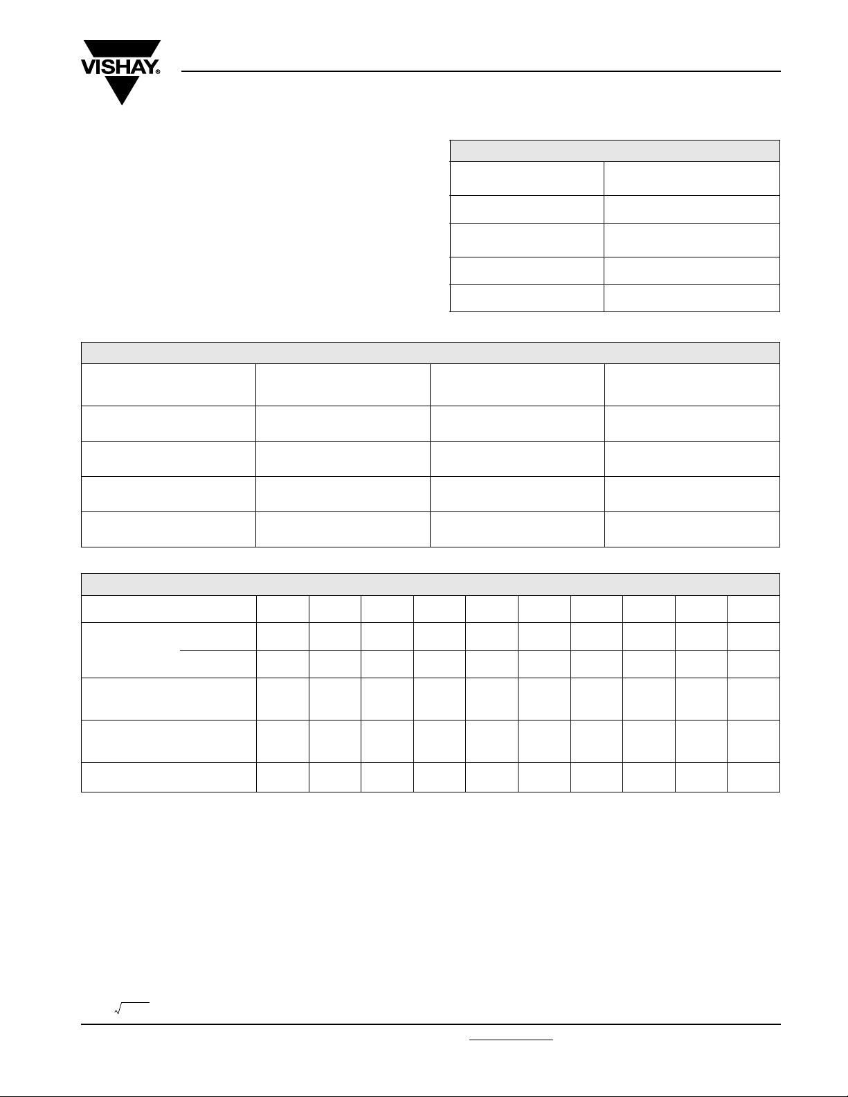
MECHANICAL SPECIFICATIONS
Mechanical Protection
Resistive Element nickel alloy wire
Connections AN collars
Average Unit Weight 10 to 1350 g
Vishay Sfernice Special cement
CS supporting collars
ENVIRONMENTAL SPECIFICATIONS
Temperature Limits - 55 °C + 450 °C
Climatic Category - 55 °C/+ 200 °C/56 days
PERFORMANCE
TESTS CONDITIONS REQUIREMENTS
Short Time Overload 10 Pr during 5 s 2 % 1 %
Climatic Sequence
Thermal Shock
Load Life
- 55 °C + 200 °C
5 cycles
Load at 100 % Pr
followed by cold - 55 °C/15
90/30 cycle
1000 h at Pr at + 25 °C
ELECTRICAL SPECIFICATIONS
Resistance Range
Standard Resistance R ≥ 10 Ω ± 5 %
Tol erance
Power Rating 14 W to 600 W at 25 °C
Temperature Coefficient + 75 ppm/°C (typical)
3 % 1 %
2 %
or 0.05 Ω
5 % 1.5 %
0.12 Ω to 560 Ω
(E12 series)
1 Ω ≤ R ≤ 10 Ω ± 10 %
0R1 ≤ R < 1 Ω ± 20 %
TYPICAL
VAL UE S
AND DRIFTS
1 %
SPECIAL FEATURES
RSSD TYPE 8 × 34 10 × 50 13 × 70 16 × 94 20 × 117 25 × 138 25 × 168 30 × 250 40 × 370 50 × 373
Powe r Ratin g
at 25 °C
Resistance Ohmic Range
(E12, E24 Series)
with 1 Tapping
Maximum Number
of Additional
Tapping
Reduction % of Ohmic
Value by Tapping
Continuous 16 W 25 W 42 W 70 W 100 W 140 W 200 W 280 W 450 W 600 W
Reduced 14 W 22 W 38 W 62 W 90 W 125 W 170 W 240 W 360 W 450 W
0.12 Ω
10 Ω
23 21 14 11 10 8 6.5 6 5.7 5.7
0.12 Ω
22 Ω
0 1 1 1 1 1 2 2 4 4
0.12 Ω
43 Ω
0.33 Ω
75 Ω
0.22 Ω
100 Ω
0.10 Ω
150 Ω
0.12 Ω
220 Ω
0.22 Ω
360 Ω
0.47 Ω
470 Ω
0.68 Ω
560 Ω
ADDITIONAL TAPPINGS
Are supplied with their adjustable collars fastened but not set to any specifi c value. Please note that, on request, all tappings can
be adjusted by VISHAY SFERNICE. For adjustment purposes we would need to be advised of the ohmic values, and tolerances
of the sections in successive order in addition to their sum Rn.
The permissible maximum value for an adjustment should take into account the possible negative tolerance of Rn.
Please consult VISHAY SFERNICE regarding the acceptable tolerance.
RECOMMENDATIONS FOR USE
Maximum Current Strength:
The ohmic value and the power decrease as the connections are brought together. To avoid overload, the maximum current
strength that is permissible for Rn should never be exceeded:
I
=
Pr/Rn
max
Document Number: 50020 For technical questions, contact: sfer@vishay.com
Revision: 24-Jan-07 71
www.vishay.com
Page 4

RSSD
Vishay Sfernice
POWER RATING CHART
TEMPERATURE RISE
Adjustable Wirewound Vitreous Resistors
Low Ohmic Values (0.10 Ω available)
100
80
60
% RATED POWER
40
0
0 100 200 300 400 450
AMBIENT TEMPERATURE IN DEGREES CELSIUS
7
8
1
3
0
4
5
400
C
°
N
I
ERUT
300
A
REPM
200
ET T
OP
S
TOH
100
3
x
x
0
8
1
D
D
S
S
S
S
R
R
R
4
07
1
9
x
x
x
0
31
D
D
S
SS
S
R
5
6
2
2
1
D
SD
S
S
S
R
R
S
R
0
8
1
5
6
2
1
x
x
x
0
5
3
2
D
D
S
S
S
S
S
R
R
0
3
7
7
3
3
x
0
0x
4
5
D
D
S
S
R
0
10 100 1000
RATED POWER IN WATTS
MARKING
SFERNICE trademark, model, style, nominal resistance (in Ω), tolerance (in %), manufacturing date.
ORDERING INFORMATION
RSSD 10 × 50 AN 10U 5 % BA25 e
MODEL STYLE SPECIAL
CONNECTIONS
TOLERANCE PACKAGING LEAD
DESIGN
Method N°
Optional
Custom items are subject to
extra charge and min. order.
Please see price list.
SAP PART NUMBERING GUIDELINES
RSSD 10 × 50 A 10R0 J S06
MODEL STYLE CONNECTIONS OHMIC VALUE TOLERANCE PACKAGING
(Pb)-FREE
www.vishay.com For technical questions, contact: sfer@vishay.com Document Number: 50020
72 Revision: 24-Jan-07
 Loading...