

Page 1

6121 Baker Road,
Suite 108
Minnetonka, MN 55345
www.chtechnology.com
Phone (952) 933-6190
Fax (952) 933-6223
1-800-274-4284
Thank you for downloading this document from C&H Technology, Inc.
Please contact the C&H Technology team for the following questions -
Technical
Application
Assembly
Availability
Pricing
Phone – 1-800-274-4284
E-Mail – sales@chtechnology.com
www.chtechnology.com - SPECIALISTS IN POWER ELECTRONIC COMPONENTS AND ASSEMBLIES - www.chtechnology.com
Page 2
RM20TPM-H
MITSUBISHI DIODE MODULES
RM20TPM-H
MEDIUM POWER GENERAL USE
INSULATED TYPE
●
IO DC output current....................... 40A
●
VRRM Repetitive peak reverse voltage
................ 800V
●
3 phase bridge
●
Insulated Type
APPLICATION
AC motor controllers, DC motor controllers, Battery DC power supplies,
DC power supplies for control panels, and other general DC power equipment
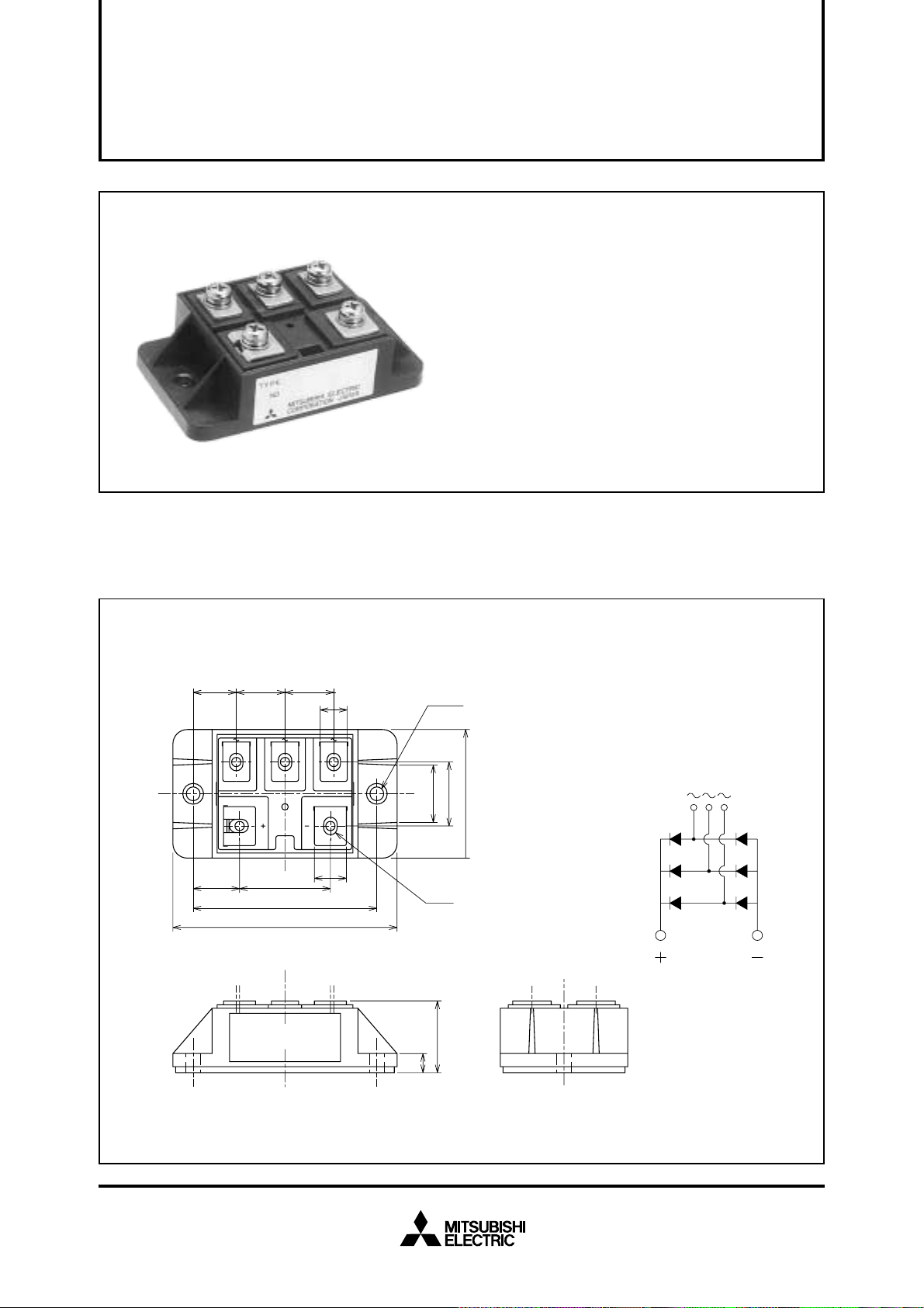
OUTLINE DRAWING & CIRCUIT DIAGRAM Dimensions in mm
13.5 15 15
14.5
28
57
70
8
10
2-φ4.5
182040
5-M4
LABEL
22
6
Mar.2002
Page 3

ABSOLUTE MAXIMUM RATINGS
Symbol
V
RRM
VRSM
Ea
Repetitive peak reverse voltage
Non-repetitive peak reverse voltage
Recommended AC input voltage
Parameter
Voltage class
H
800
900
220
MITSUBISHI DIODE MODULES
RM20TPM-H
MEDIUM POWER GENERAL USE
INSULATED TYPE
Unit
V
V
V
Symbol
O
I
IFSM
2
t
I
f
j
T
Tstg
Viso
DC output current
Surge (non-repetitive) forward current
2
t
I
Maximum operating frequency
Junction temperature
Storage temperature
Isolation voltage
—
Mounting torque
—
Weight
Parameter
for fusing
ELECTRICAL CHARACTERISTICS
Symbol
I
RRM
VFM
Rth (j-c)
Rth (c-f)
Repetitive reverse current
Forward voltage
Thermal resistance
Contact thermal resistance
—
Insulation resistance
Parameter
Conditions
Three-phase full wave rectifying circuit, T
One half cycle at 60Hz, peak value
Value for one cycle of surge current
Charged part to case
Main terminal screw M4
Mounting screw M4
Typical value
Test conditions
T
j=150°C, VRRM applied
j=25°C, IFM=40A, instantaneous meas.
T
Junction to case
Case to fin, conductive grease applied
Measured with a 500V megohmmeter between main terminal
and case
C=125°C
Min.
—
—
—
—
10
Ratings
40
400
4.2 × 10
1000
–40~+150
–40~+125
2500
0.98~1.47
10~15
0.98~1.47
10~15
100
Limits
Typ.
—
—
—
—
—
Unit
A
A
3
Max.
10
1.2
0.33
0.09
—
2
A
Hz
°C
°C
V
N·m
kg·cm
N·m
kg·cm
g
Unit
mA
V
°C/W
°C/W
MΩ
s
Mar.2002
Page 4

PERFORMANCE CURVES
MITSUBISHI DIODE MODULES
RM20TPM-H
MEDIUM POWER GENERAL USE
INSULATED TYPE
MAXIMUM FORWARD CHARACTERISTIC ALLOWABLE SURGE (NON-REPETITIVE)
FORWARD CURRENT
10
3
2
2
Tj=25°C
7
500
400
5
FORWARD CURRENT (A)
3
2
1
10
7
5
3
2
0
10
7
5
0.8 1.0 1.6 2.0
0.6
1.4
FORWARD VOLTAGE (V)
1.81.2
300
200
100
FORWARD CURRENT (A)
SURGE (NON-REPETITIVE)
0
CONDUCTION TIME
101 100
(CYCLES AT 60Hz)
MAXIMUM TRANSIENT THERMAL IMPEDANCE
MAXIMUM POWER DISSIPATION
(JUNCTION TO CASE)
(°C/W)
0.35
0.30
0.25
0.20
0.15
0
232
10
1
753
10
70
60
50
40
30
705030207532
0.10
0.05
TRANSIENT THERMAL IMPEDANCE
0
–3
10
ALLOWABLE CASE TEMPERATURE
130
120
110
100
90
80
CASE TEMPERATURE (°C)
70
60
05010
–2
10
7532
–1
10
7532 7532
TIME (s) DC OUTPUT CURRENT (A)
VS. DC OUTPUT CURRENT
20 4030
DC OUTPUT CURRENT (A)
10
20
POWER DISSIPATION (W)
10
0
0
05010
20 4030
Mar.2002
 Loading...