

Page 1

6121 Baker Road,
Suite 108
Minnetonka, MN 55345
www.chtechnology.com
Phone (952) 933-6190
Fax (952) 933-6223
1-800-274-4284
Thank you for downloading this document from C&H Technology, Inc.
Please contact the C&H Technology team for the following questions -
Technical
Application
Assembly
Availability
Pricing
Phone – 1-800-274-4284
E-Mail – sales@chtechnology.com
www.chtechnology.com - SPECIALISTS IN POWER ELECTRONIC COMPONENTS AND ASSEMBLIES - www.chtechnology.com
Page 2
RLP
Vishay Sfernice
Insulated Precision Wirewound Resistors
Axial Leads
In wirewound precision resistors, the RLP series holds a
leading position in professional applications whenever an
excellent stability of the ohmic value and a correspondingly
low temperature coefficient are required at the same time.
The RLP model resistors comply with the most stringent
requirements of the EN 140-100 specification. The series
consists of 5 models covering the power range from 1 W to
10 W.
Non-inductive versions can be supplied on request by
specifying RLP-NI. For higher power dissipations, the use of
RH series resistors is recommended.
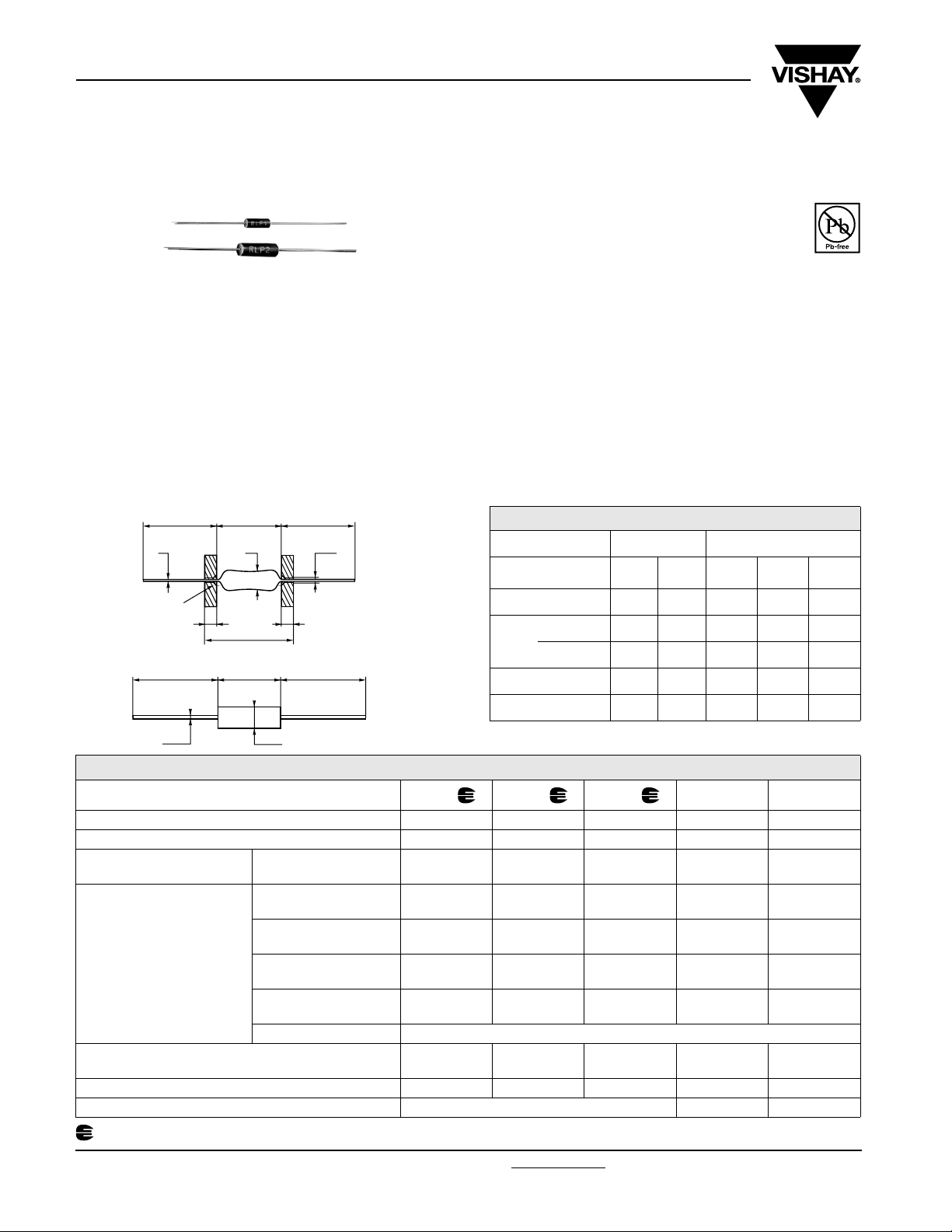
DIMENSIONS in millimeters
25 min.
Ø E
° chamfer
45
max. 0.25 deep
25 min.
Ø E
INSULATED
4
MOLDED
A
Ø B
L max.
A
4
Ø B
25 min.
Ø a ± 0.02
RLP1 - RLP2 a = 1 mm
RLP3 - 6 - 10 a = 1.2 mm
25 min.
RLP 1 - RLP 2
FEATURES
• 1 W to 10 W at 25 °C
• CECC 40201-006
• Conforms to EN 140-100
RoHS
COMPLIANT
• Excellent stability < ± 0.3 % after 1000 h
• High power up to 10 W at 25 °C
• Low ohmic values 10 mΩ available
• Low temperature coefficient ≤ ± 50 ppm/°C
• Electrical insulation
• Climatic protection
• Termination = Pure matte tin or Sn/Ag/Cu according to the
ohmic value
DIMENSIONS in millimeters
MOLDED INSULATED
SERIES
AND STYLE
A max. 7 10.2 14 23.82 46.78
R > 0.15 Ω 2.5 4.0 5.54 8.71 10.32
Ø B
max.
R ≤ 0.15 Ω - 6 9 11 180K
E ± 0.1 0.6 0.6 0.8 0.8 0.8
Weight in g 0.27 0.48 1.3 3.4 8.6
RLP 1 RLP 2 RLP 3 RLP 6 RLP 10
TECHNICAL SPECIFICATIONS
VISHAY SFERNICE SERIES AND STYLE RLP1 RLP2 RLP3 RLP6 RLP10
NF C 83-210 RP8 RP7 RP4 - -
CECC 40201-006 ABC- -
Power Rating
at + 25 °C
Ohmic Range
in Relation
to Tolerance
Qualified Ohmic Range
NF C 83-210
Limiting Element Voltage 50 V 120 V 200 V 300 V 720 V
Critical Resistance out of nominal ohmic range 17 800 Ω 51 100 Ω
Undergoes European Quality Insurance System (CECC)
www.vishay.com For technical questions, contact: sfer@vishay.com
41 Revision: 04-Jul-07
VISHAY SFERNICE
Limits
± 5 % E24
± 2 % E48
± 1 % E96
± 0.5 % E96
1 W2 W3 W6 W10 W
0.05 Ω
2.2 kΩ
0.05 Ω
2.2 kΩ
0.05 Ω
2.2 kΩ
0.4 Ω
2.2 kΩ
0.025 Ω
6.8 kΩ
0.025 Ω
6.8 kΩ
0.025 Ω
6.8 kΩ
0.4 Ω
6.8 kΩ
0.01 Ω
15 kΩ
0.03 Ω
15 kΩ
0.03 Ω
15 kΩ
0.0499 Ω
15 kΩ
0.02 Ω
59 kΩ
0.02 Ω
59 kΩ
0.02 Ω
59 kΩ
0.3 Ω
59 kΩ
± 0.1 % E96 Please consult VISHAY SFERNICE
1 Ω
470 Ω
0.2 Ω
1.78 kΩ
0.1 Ω
3.57 kΩ
0.1 Ω
12.1 kΩ
Document Number: 50009
0.06 Ω
150 kΩ
0.06 Ω
150 kΩ
0.06 Ω
150 kΩ
0.3 Ω
150 kΩ
0.1 Ω
40.2 kΩ
Page 3

RLP
Insulated Precision Wirewound Resistors
Axial Leads
PERFORMANCE
TESTS CONDITIONS
Dielectric w/s Voltage
Short Time Overload
Climatic Sequence
Humidity (Steady State)
Vibration
Load Life
Moisture Resistance
500 VRMS for RLP 1-2-3
1000 VRMS for RLP 6-10
5 Pn/5 s for Pn < 5 W
10 Pn/5 s for Pn ≥ 5 W
EN 140-201
fasc. 19A - 55 °C/+ 200 °C
fasc. 3A 56 days 95 % R.H.
Method 204 - Test D: 20 g
5 cycles
EN 140-201
MIL-STD-202
10/2000 Hz
MIL-STD-202
Method 108 Pn 1000 h
MIL-STD-202
Method 106
MIL-R-26 E CECC40201-06
± (0.1 % + 0.05 Ω) - ± (0.05 % + 0.05 Ω)
± (0.2 % + 0.05 Ω) ± 0.25 % + 0.05 Ω ± (0.1 % + 0.05 Ω)
± (0.1 % + 0.05 Ω) ± 0.25 % + 0.05 Ω ± (0.05 % + 0.05 Ω)
± (0.5 % + 0.05 Ω)
± (0.2 % + 0.05 Ω)
Insulation resistance
> 100 MΩ
High Temperature 250 h at + 275 °C ± (0.5 % + 0.05 Ω)
Shock
MIL-STD-202
100 g Method 205 - Test C
± (0.1% + 0.05 Ω) ± 0.25 % + 0.05 Ω ± (0.05 % + 0.05 Ω)
REQUIREMENTS TYPICAL VALUES
-
-
± 0.5 % + 0.05 Ω
Insulation R > 100 MΩ
± 0.5 % + 0.05 Ω
Insulation R > 100 MΩ
± 0.5 % + 0.05 Ω
Insulation R ≥ 1 GΩ
-
± 0.5 % + 0.05 Ω
Insulation R ≥ 1 GΩ
Vishay Sfernice
AND DRIFTS
± (0.2 % + 0.05 Ω)
Ins. resistance > 10
± (0.25 % + 0.05 Ω)
Ins. resistance > 10
± (0.3 % + 0.05 Ω)
± (1 % + 0.05 Ω)
Ins. resistance > 10
± (0.25 % + 0.05 Ω)
3
MΩ
3
MΩ
3
MΩ
TEMPERATURE COEFFICIENT IN THE RANGE - 55 °C TO + 200 °C
OHMIC RANGE
NF C MIL
< 1 Ω ± 100 ppm/°C ± 90 ppm/°C
1 Ω to < 10 Ω ± 50 ppm/°C ± 50 ppm/°C
≥ 10 Ω ± 25 ppm/°C ± 30 ppm/°C + 0 to - 20 ppm/°C
LIMITS
TYPICAL VALUE
± 50 ppm/°C
STABILITY AND POWER RATING
Stability changes slightly according to power rating and ambient temperature. This fact is especially important for users needing
a life drift lower than the initial resistance tolerance. Typical drifts, after 2000 hours life test made under the 90’/30’ conditions and
at an ambient temperature of 25 °C, are:
OHMIC RANGE RLP1 RLP2 RLP3 RLP6 RLP10
Pn 1 W 2 W 3 W 5 W 10 W 0.3
0.5 Pn 0.5 W 1 W 1.5 W 2.5 W 5 W 0.15
ΔR %
R %
INDUCTANCE (Example)
1.4
1.3
1.2
1.1
H
µ N I E C N A T C U D N I
1.0
0.9
0.8
0.7
0.6
0.5
0.4
0.3
0.2
0.1
0
0.1 1 10
FREQUENCY IN MHz
RLP3 NI 100 Ω
Document Number: 50009 For technical questions, contact: sfer@vishay.com
Revision: 04-Jul-07 42
0 0 1 3 P
L R Ω
www.vishay.com
Page 4

RLP
Vishay Sfernice
POWER RATING CHART
TEMPERATURE RISE
Insulated Precision Wirewound Resistors
Axial Leads
125
100
75
50
% RATED POWER
37
25
0
0 50 100 150 200 250 275 300 350
AMBIENT TEMPERATURE IN ° C
250
0
1
P L
R
200
150
6
2
P L R
1
P L R
3 P
L R
P L
R
100
50
HOT SPOT TEMPERATURE IN °C
0
0 1.5 3.0 4.5 6.0 7.5 10.0
RATED POWER IN W
MARKING
SFERNICE trademark, series, style, CECC style (if applicable) nominal resistance (in Ω, kΩ), tolerance (in %), manufacturing
date.
ORDERING INFORMATION
RLP 1 XXX 5U5 ± 5 % TR100 e1
MODEL STYLE NON INDUCTIVE
WINDING
Optional
(NI)
SPECIAL
DESIGN
Method N°
Optional
OHMIC VALUE
Custom items
are subject to
extra-charge
and min. order.
Please see
TOLERANCE PACKAGING
Optional
LEAD
(Pb)-FREE
price list.
SAP PART NUMBERING GUIDELINES
RLP 01 5R500 J R15
MODEL STYLE OHMIC VALUE TOLERANCE PACKAGING
www.vishay.com For technical questions, contact: sfer@vishay.com Document Number: 50009
43 Revision: 04-Jul-07
 Loading...